EP4306071A1 - Système pour l'enregistrement d'images 3d et 2d pour navigation chirurgicale et guidage robotique sans utiliser de repères radio-opaques dans les images - Google Patents
Système pour l'enregistrement d'images 3d et 2d pour navigation chirurgicale et guidage robotique sans utiliser de repères radio-opaques dans les images Download PDFInfo
- Publication number
- EP4306071A1 EP4306071A1 EP23185949.7A EP23185949A EP4306071A1 EP 4306071 A1 EP4306071 A1 EP 4306071A1 EP 23185949 A EP23185949 A EP 23185949A EP 4306071 A1 EP4306071 A1 EP 4306071A1
- Authority
- EP
- European Patent Office
- Prior art keywords
- image
- images
- patient
- imaging
- markers
- Prior art date
- Legal status (The legal status is an assumption and is not a legal conclusion. Google has not performed a legal analysis and makes no representation as to the accuracy of the status listed.)
- Pending
Links
Images
















Classifications
-
- A—HUMAN NECESSITIES
- A61—MEDICAL OR VETERINARY SCIENCE; HYGIENE
- A61B—DIAGNOSIS; SURGERY; IDENTIFICATION
- A61B34/00—Computer-aided surgery; Manipulators or robots specially adapted for use in surgery
- A61B34/20—Surgical navigation systems; Devices for tracking or guiding surgical instruments, e.g. for frameless stereotaxis
-
- A—HUMAN NECESSITIES
- A61—MEDICAL OR VETERINARY SCIENCE; HYGIENE
- A61B—DIAGNOSIS; SURGERY; IDENTIFICATION
- A61B34/00—Computer-aided surgery; Manipulators or robots specially adapted for use in surgery
- A61B34/30—Surgical robots
-
- A—HUMAN NECESSITIES
- A61—MEDICAL OR VETERINARY SCIENCE; HYGIENE
- A61B—DIAGNOSIS; SURGERY; IDENTIFICATION
- A61B34/00—Computer-aided surgery; Manipulators or robots specially adapted for use in surgery
- A61B34/30—Surgical robots
- A61B34/32—Surgical robots operating autonomously
-
- G—PHYSICS
- G06—COMPUTING OR CALCULATING; COUNTING
- G06T—IMAGE DATA PROCESSING OR GENERATION, IN GENERAL
- G06T7/00—Image analysis
- G06T7/30—Determination of transform parameters for the alignment of images, i.e. image registration
- G06T7/33—Determination of transform parameters for the alignment of images, i.e. image registration using feature-based methods
- G06T7/337—Determination of transform parameters for the alignment of images, i.e. image registration using feature-based methods involving reference images or patches
-
- G—PHYSICS
- G06—COMPUTING OR CALCULATING; COUNTING
- G06T—IMAGE DATA PROCESSING OR GENERATION, IN GENERAL
- G06T7/00—Image analysis
- G06T7/70—Determining position or orientation of objects or cameras
-
- G—PHYSICS
- G06—COMPUTING OR CALCULATING; COUNTING
- G06V—IMAGE OR VIDEO RECOGNITION OR UNDERSTANDING
- G06V10/00—Arrangements for image or video recognition or understanding
- G06V10/70—Arrangements for image or video recognition or understanding using pattern recognition or machine learning
- G06V10/74—Image or video pattern matching; Proximity measures in feature spaces
-
- G—PHYSICS
- G06—COMPUTING OR CALCULATING; COUNTING
- G06V—IMAGE OR VIDEO RECOGNITION OR UNDERSTANDING
- G06V20/00—Scenes; Scene-specific elements
- G06V20/60—Type of objects
- G06V20/64—Three-dimensional [3D] objects
- G06V20/647—Three-dimensional [3D] objects by matching two-dimensional images to three-dimensional objects
-
- A—HUMAN NECESSITIES
- A61—MEDICAL OR VETERINARY SCIENCE; HYGIENE
- A61B—DIAGNOSIS; SURGERY; IDENTIFICATION
- A61B34/00—Computer-aided surgery; Manipulators or robots specially adapted for use in surgery
- A61B34/10—Computer-aided planning, simulation or modelling of surgical operations
- A61B2034/107—Visualisation of planned trajectories or target regions
-
- A—HUMAN NECESSITIES
- A61—MEDICAL OR VETERINARY SCIENCE; HYGIENE
- A61B—DIAGNOSIS; SURGERY; IDENTIFICATION
- A61B34/00—Computer-aided surgery; Manipulators or robots specially adapted for use in surgery
- A61B34/20—Surgical navigation systems; Devices for tracking or guiding surgical instruments, e.g. for frameless stereotaxis
- A61B2034/2046—Tracking techniques
- A61B2034/2051—Electromagnetic tracking systems
-
- A—HUMAN NECESSITIES
- A61—MEDICAL OR VETERINARY SCIENCE; HYGIENE
- A61B—DIAGNOSIS; SURGERY; IDENTIFICATION
- A61B34/00—Computer-aided surgery; Manipulators or robots specially adapted for use in surgery
- A61B34/20—Surgical navigation systems; Devices for tracking or guiding surgical instruments, e.g. for frameless stereotaxis
- A61B2034/2046—Tracking techniques
- A61B2034/2055—Optical tracking systems
-
- A—HUMAN NECESSITIES
- A61—MEDICAL OR VETERINARY SCIENCE; HYGIENE
- A61B—DIAGNOSIS; SURGERY; IDENTIFICATION
- A61B34/00—Computer-aided surgery; Manipulators or robots specially adapted for use in surgery
- A61B34/20—Surgical navigation systems; Devices for tracking or guiding surgical instruments, e.g. for frameless stereotaxis
- A61B2034/2046—Tracking techniques
- A61B2034/2059—Mechanical position encoders
-
- A—HUMAN NECESSITIES
- A61—MEDICAL OR VETERINARY SCIENCE; HYGIENE
- A61B—DIAGNOSIS; SURGERY; IDENTIFICATION
- A61B34/00—Computer-aided surgery; Manipulators or robots specially adapted for use in surgery
- A61B34/20—Surgical navigation systems; Devices for tracking or guiding surgical instruments, e.g. for frameless stereotaxis
- A61B2034/2046—Tracking techniques
- A61B2034/2065—Tracking using image or pattern recognition
-
- A—HUMAN NECESSITIES
- A61—MEDICAL OR VETERINARY SCIENCE; HYGIENE
- A61B—DIAGNOSIS; SURGERY; IDENTIFICATION
- A61B34/00—Computer-aided surgery; Manipulators or robots specially adapted for use in surgery
- A61B34/20—Surgical navigation systems; Devices for tracking or guiding surgical instruments, e.g. for frameless stereotaxis
- A61B2034/2068—Surgical navigation systems; Devices for tracking or guiding surgical instruments, e.g. for frameless stereotaxis using pointers, e.g. pointers having reference marks for determining coordinates of body points
-
- A—HUMAN NECESSITIES
- A61—MEDICAL OR VETERINARY SCIENCE; HYGIENE
- A61B—DIAGNOSIS; SURGERY; IDENTIFICATION
- A61B90/00—Instruments, implements or accessories specially adapted for surgery or diagnosis and not covered by any of the groups A61B1/00 - A61B50/00, e.g. for luxation treatment or for protecting wound edges
- A61B90/36—Image-producing devices or illumination devices not otherwise provided for
- A61B90/37—Surgical systems with images on a monitor during operation
- A61B2090/374—NMR or MRI
-
- A—HUMAN NECESSITIES
- A61—MEDICAL OR VETERINARY SCIENCE; HYGIENE
- A61B—DIAGNOSIS; SURGERY; IDENTIFICATION
- A61B90/00—Instruments, implements or accessories specially adapted for surgery or diagnosis and not covered by any of the groups A61B1/00 - A61B50/00, e.g. for luxation treatment or for protecting wound edges
- A61B90/36—Image-producing devices or illumination devices not otherwise provided for
- A61B90/37—Surgical systems with images on a monitor during operation
- A61B2090/376—Surgical systems with images on a monitor during operation using X-rays, e.g. fluoroscopy
-
- A—HUMAN NECESSITIES
- A61—MEDICAL OR VETERINARY SCIENCE; HYGIENE
- A61B—DIAGNOSIS; SURGERY; IDENTIFICATION
- A61B90/00—Instruments, implements or accessories specially adapted for surgery or diagnosis and not covered by any of the groups A61B1/00 - A61B50/00, e.g. for luxation treatment or for protecting wound edges
- A61B90/36—Image-producing devices or illumination devices not otherwise provided for
- A61B90/37—Surgical systems with images on a monitor during operation
- A61B2090/376—Surgical systems with images on a monitor during operation using X-rays, e.g. fluoroscopy
- A61B2090/3762—Surgical systems with images on a monitor during operation using X-rays, e.g. fluoroscopy using computed tomography systems [CT]
-
- A—HUMAN NECESSITIES
- A61—MEDICAL OR VETERINARY SCIENCE; HYGIENE
- A61B—DIAGNOSIS; SURGERY; IDENTIFICATION
- A61B90/00—Instruments, implements or accessories specially adapted for surgery or diagnosis and not covered by any of the groups A61B1/00 - A61B50/00, e.g. for luxation treatment or for protecting wound edges
- A61B90/36—Image-producing devices or illumination devices not otherwise provided for
- A61B90/37—Surgical systems with images on a monitor during operation
- A61B2090/376—Surgical systems with images on a monitor during operation using X-rays, e.g. fluoroscopy
- A61B2090/3762—Surgical systems with images on a monitor during operation using X-rays, e.g. fluoroscopy using computed tomography systems [CT]
- A61B2090/3764—Surgical systems with images on a monitor during operation using X-rays, e.g. fluoroscopy using computed tomography systems [CT] with a rotating C-arm having a cone beam emitting source
-
- A—HUMAN NECESSITIES
- A61—MEDICAL OR VETERINARY SCIENCE; HYGIENE
- A61B—DIAGNOSIS; SURGERY; IDENTIFICATION
- A61B90/00—Instruments, implements or accessories specially adapted for surgery or diagnosis and not covered by any of the groups A61B1/00 - A61B50/00, e.g. for luxation treatment or for protecting wound edges
- A61B90/39—Markers, e.g. radio-opaque or breast lesions markers
- A61B2090/3937—Visible markers
-
- A—HUMAN NECESSITIES
- A61—MEDICAL OR VETERINARY SCIENCE; HYGIENE
- A61B—DIAGNOSIS; SURGERY; IDENTIFICATION
- A61B90/00—Instruments, implements or accessories specially adapted for surgery or diagnosis and not covered by any of the groups A61B1/00 - A61B50/00, e.g. for luxation treatment or for protecting wound edges
- A61B90/39—Markers, e.g. radio-opaque or breast lesions markers
- A61B2090/3983—Reference marker arrangements for use with image guided surgery
-
- G—PHYSICS
- G06—COMPUTING OR CALCULATING; COUNTING
- G06T—IMAGE DATA PROCESSING OR GENERATION, IN GENERAL
- G06T2207/00—Indexing scheme for image analysis or image enhancement
- G06T2207/10—Image acquisition modality
- G06T2207/10116—X-ray image
- G06T2207/10121—Fluoroscopy
-
- G—PHYSICS
- G06—COMPUTING OR CALCULATING; COUNTING
- G06T—IMAGE DATA PROCESSING OR GENERATION, IN GENERAL
- G06T2207/00—Indexing scheme for image analysis or image enhancement
- G06T2207/10—Image acquisition modality
- G06T2207/10116—X-ray image
- G06T2207/10124—Digitally reconstructed radiograph [DRR]
-
- G—PHYSICS
- G06—COMPUTING OR CALCULATING; COUNTING
- G06T—IMAGE DATA PROCESSING OR GENERATION, IN GENERAL
- G06T2207/00—Indexing scheme for image analysis or image enhancement
- G06T2207/30—Subject of image; Context of image processing
- G06T2207/30004—Biomedical image processing
- G06T2207/30008—Bone
Definitions
- the present invention relates to navigation systems, and more particularly, to a system and method of registering a medical image of a patient in an imaging space to the patient in a physical space.
- Surgical navigation has revolutionized minimally invasive spine surgery by allowing surgeons to accurately and repeatably place implant hardware with decreased radiation and operative time as opposed to conventional surgical techniques.
- a position sensor is used to track full rigid body motion of surgical instruments with respect to a medical image registered to a patient reference frame.
- the most common form of position sensing is optical tracking, specifically near infrared (NIR) passive retroreflective markers or active NIR LEDs arranged in a pattern called an array.
- NIR near infrared
- the position of the tracked instruments is typically displayed to the surgeon user as a CAD model of the instrument overlaid on the medical image.
- Robotic guidance is a technology where a robotic arm is positioned on the desired trajectory and used to guide the instruments on an accurate and repeatable trajectory.
- eGPS ExcelsiusGPS
- robotic navigation has been integrated with surgical navigation in a single system called robotic navigation.
- Robotic navigation offers the benefits of both technologies in a single streamlined system.
- Registration of optical navigation systems typically involve the use of a registration fixture, which contains an array of tracking markers positioned in known locations with respect to an array of embedded radiopaque fiducials.
- the fixture is attached to the patient and surrounding structures such as the imaging system such that the fiducials are embedded in the medical image and tracking markers are visible to the position sensor (e.g., stereoscopic camera of a tracking device).
- the position sensor e.g., stereoscopic camera of a tracking device.
- the system can then compute multiple transformations to register the medical image to the tracking system.
- registration fixtures intraoperatively.
- the primary drawback is a requirement that the image volume be captured with radiopaque fiducials already in place on the patient, meaning that scans of a patient taken preoperatively cannot be used for navigation.
- An additional drawback is the loss of usable image space due to inclusion of the fixture fiducials within the image volume/area.
- the fiducials can sometimes obstruct the view of critical anatomy.
- registration fixtures are additional hardware components that must be stored, cleaned, draped/sterilized, and installed intraoperatively, leading to increased time and complexity for the surgical staff.
- some companies e.g., Medtronic O-arm and SteathStation have developed methods of obtaining registered intraoperative images without the need for a registration fixture (automatic registration).
- these systems have integrated or detachable tracking arrays at known locations of the imaging system.
- An associated navigation system can then be used to track the position of the imaging system navigation array relative to the patient reference array to complete the image registration.
- the primary failure mode of navigated surgery is loss of registration due to shift of patient anatomy relative to the patient reference array. If registration is lost during a surgical procedure, the surgical team needs to return the 3D imaging system to the surgical site and capture new registered images. The need for this additional 3D image exposes the patient to significant additional radiation, increases time under anesthesia, and decreases efficiency for the hospital.
- a system and method of registering a pre-op 3D medical image of a patient in an imaging space to the patient in a tracked space receives a 3D image of a patient anatomy which was taken with an imaging device pre-operatively. At this point, the 3D image has not been registered with the patient lying on an operating table. Once the patient has been prepared and is lying on an operating table, an imaging device is rolled in and an intra-op 2D image of the patient anatomy is captured by the imaging device having imaging tracking markers trackable by a tracking device (e.g., optical or electromagnetic tracking system).
- a tracking device e.g., optical or electromagnetic tracking system
- the system receives a corresponding optical image of the patient from the tracking device at the time of image capture, the optical image containing the imaging tracking markers and a dynamic reference base (DRB) including patient tracking markers trackable by the tracking device.
- DRB dynamic reference base
- the 2D image is then matched to a corresponding 2D simulated medical image, which is a synthetically generated medical image at a selected orientation and position, which has been digitally reconstructed from the pre-op 3D image.
- the simulated image is a DRR (digitally reconstructed radiograph) of the pre-op 3D image.
- the DRR is a simulated 2D fluoroscopic image at a selected orientation and angle, which has been digitally reconstructed from the pre-op 3D image (e.g., a set/stack of 2D slices of the 3D image volume).
- an ultrasound it would be a synthetically generated 2D image representing an ultrasound scan at a particular orientation and position from the pre-op 3D image.
- the system determines a registration of the pose of the received pre-op 3D image relative to the dynamic reference base based on the matched DRR, and the patient tracking markers and the imaging tracking markers contained in the received optical image. Registration is achieved because the pose of the matched DRR corresponds to the tracked pose of the actual 2D image.
- the method then displays the registered 3D images and any selected 2D DRR of the 3D image on a display along with tracked surgical instruments, its planned trajectory and end effector superimposed on top of the displayed 3D image for visual navigation assistance.
- the registration method requires no radiopaque fiducials to be present in the medical images, and there is no need to attach any registration fixture to the imaging device as was previously necessary.
- the present method may substantially reduce procedure time and increase patient safety.
- a system and method of registering an intra-op 3D image (such as a 3D CT or MRI image) of a patient in an imaging space to the physical patient in a tracked physical space without embedding fiducials (e.g., radiopaque markers) in images is disclosed.
- the system receives an intra-op image of a patient anatomy which has been captured by an imaging device having imaging tracking markers trackable by a tracking device, the patient having a dynamic reference base including patient tracking markers trackable by the tracking device.
- the system also receives an optical image of the patient from the tracking device at the time of image capture, the optical image containing the patient tracking markers and the imaging tracking markers.
- Transform A representing the pose of the imaging device relative to the dynamic reference base is determined based on the received optical image.
- Transform B representing the pose of the received image of the patient anatomy relative to the imaging device is determined based on the received optical image.
- Transform C representing the pose of the received image relative to the dynamic reference base is determined by multiplying transform A and transform B.
- Transform C represents the registration of the patient image in the imaging space to the physical patient in a physical space, all of the transforms being performed without the use of any fiducials.
- the method then displays the registered images on a display along with tracked surgical instruments, its planned trajectory and end effector superimposed on top of the displayed 3D image for visual navigation assistance.
- the present method may substantially reduce procedure time and increase patient safety. Also because no pre-op scan of the patient is necessary, it may save cost and may eliminate any unnecessary radiation exposure to the patient.
- a system and method for recovering registration of a 3D image of a patient in an imaging space to the physical patient in a physical space receives a 3D image of a patient anatomy and registers a pose of the received 3D image relative to a dynamic reference base containing patient tracking markers. The registered 3D image is then used during the surgical procedure.
- the system receives two or more intra-op 2D images (e.g., fluoroscopic or ultrasound) of the patient anatomy at different orientations that have been captured by an imaging device having imaging tracking markers trackable by a tracking device (e.g., optical or electromagnetic).
- the system also receives corresponding optical images of the patient from the tracking device at the time of image capture, the optical images containing the patient tracking markers and the imaging tracking markers.
- the received 2D images are matched to corresponding simulated 2D images (e.g., DRR) of the 3D image.
- Registration of the 3D image is re-established based on the matched corresponding DRRs, and the patient tracking markers and the imaging tracking markers contained in the optical images.
- the method then displays the registered 3D image on a display along with tracked surgical instruments, its planned trajectory and end effector superimposed on top of the displayed 3D image for visual navigation assistance.
- the present method may substantially reduce procedure time and increase patient safety.
- a system and method of registering intra-op 2D medical images of a patient in an imaging space to the physical patient in a physical space receives intra-op 2D images of the patient anatomy at different orientations which have been captured by an imaging device having imaging tracking markers trackable by a tracking device; the patient having a dynamic reference base including patient tracking markers trackable by the tracking device.
- the system also receives corresponding optical images of the patient from the tracking device at the time of image capture, the optical images containing the patient tracking markers and the imaging tracking markers.
- Transform C represents the registration of the patient image in the imaging space to the physical patient in a physical space, all of the transforms being performed without the use of any radiopaque fiducials.
- the method then displays the registered 2D images on a display along with tracked surgical instruments, its planned trajectory and end effector superimposed on top of the displayed 2D images for visual navigation assistance.
- a system and method of registering intra-op 2D images of a patient in an imaging space to the physical patient in a physical space receives intra-op 2D images of the patient anatomy at different orientations which have been captured by an imaging device having imaging tracking markers trackable by a tracking device; the patient having a dynamic reference base including patient tracking markers trackable by the tracking device.
- the system also receives corresponding optical images of the patient from the tracking device at the time of image capture, the optical images containing the patient tracking markers and the imaging tracking markers.
- the method creating a customized 3D model. For each received 2D image, the method determines transforms A, B and C as discussed above to register the 2D images. The 2D images are matched to corresponding DRRs of the customized 3D model such that the customized model can be registered based on the matched DRRs.
- the method then displays the registered 3D images on a display along with tracked surgical instruments, its planned trajectory and end effector superimposed on top of the displayed 2D images for visual navigation assistance.
- This method allows navigation with synthetically created 3D model even when access to a 3D scanning imaging device is not available.
- code For purposes of this application, the terms "code”, “software”, “program”, “application”, “software code”, “software module”, “module” and “software program” are used interchangeably to mean software instructions that are executable by a processor.
- a “user” can be a physician or other medical professional.
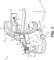
- FIG. 1 is a schematic diagram showing an imaging system 10, such as a computerized tomographic (CT) x-ray scanner, in accordance with one embodiment of the invention.
- the imaging system 10 includes a movable station 60 and a gantry 56.
- the movable station includes a vertical shaft 59 and a gantry mount 58 which is rotatably attached to the vertical shaft.
- the movable station 60 includes two front omni-directional wheels 62 and two rear omni-directional wheels 64, which together provide movement of the movable station 60 in any direction in an X-Y plane.
- the omni-directional wheels 62,64 can be obtained, for example, from Active Robots Limited of Somerset, U.K.
- a pair of handles 13 mounted to the housing of the movable station 60 allow a user to manually maneuver the station.
- a motor 66 attached to the vertical shaft 59 is designed to rotate the gantry mount 58 full 360 degrees about the X-axis and a motor 67 moves the gantry mount 58 vertically along the z-axis under the control of the control module 51.
- the gantry 56 includes a first C-arm 70 slidably coupled to the gantry mount 58 and a second C-arm 72 which is slidably coupled to the first C-arm.
- the first and second C-arms 70,72 are outer and inner C-arms, respectively.
- the outer and inner C-arms 70,72 are circular in shape and rotate circumferentially about a central axis so as to allow imaging of a patient who is lying in bed 16 without the need to transfer the patient.
- An imaging signal transmitter 74 such as an X-ray beam transmitter is mounted to one side of the second C-arm 72 while an imaging sensor 74 such as an X-ray detector array is mounted to the other side of the second C-arm and faces the transmitter.
- the X-ray transmitter 74 transmits an X-ray beam which is received by the X-ray detector 76 after passing through a relevant portion of a patient (not shown).
- the system 10 is a multi-modality x-ray imaging system designed with surgery in mind.
- the three imaging modalities include fluoroscopy, 2D Radiography, and Cone-beam CT.
- Fluoroscopy is a medical imaging technique that shows a continuous X-ray image on a monitor, much like an X-ray movie.
- 2D Radiography is an imaging technique that uses X-rays to view the internal structure of a non-uniformly composed and opaque object such as the human body.
- CBCT cone beam 3D imaging or cone beam computer tomography
- C-arm CT is a medical imaging technique consisting of X-ray computed tomography where the X-rays are divergent, forming a cone.
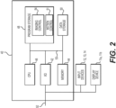
- the movable station 60 includes an imaging controller system 40 which serves a dual function of (1) controlling the movement of the omni-directional wheels 62,64, gantry mount 58 and the gantry 56 to position the imaging signal transmitter 74 in relation to the patient, and (2) controlling imaging functions for imaging the patient once the gantry 56 has been properly positioned.
- an imaging controller system 40 which serves a dual function of (1) controlling the movement of the omni-directional wheels 62,64, gantry mount 58 and the gantry 56 to position the imaging signal transmitter 74 in relation to the patient, and (2) controlling imaging functions for imaging the patient once the gantry 56 has been properly positioned.
- the imaging controller system 40 of the present invention is connected to a communication link 52 through an I/O interface 42 such as a USB (universal serial bus) interface, which receives information from and sends information over the communication link 52.
- the imaging controller system 40 includes memory storage 44 such as RAM (random access memory), processor (CPU) 46, program storage 48 such as ROM or EEPROM, and data storage 50 such as a hard disk, all commonly connected to each other through a bus 53.
- the program storage 48 stores, among others, imaging control module 54 and motion control module 51, each containing software to be executed by the processor 46.
- the motion control module 51 executed by the processor 46 controls the wheels 62,64 of the movable station 60 and various motors in the gantry mount 58 and gantry 56 to position the station 60 near the patient and position the gantry in an appropriate position for imaging a relevant part of the patient.
- the imaging control module 54 executed by the processor 46 controls the imaging signal transmitter 74 and detector array 76 to image the patient body.
- the imaging control module images different planar layers of the body and stores them in the memory 44.
- the imaging control module 54 can process the stack of images stored in the memory 44 and generate a three dimensional image.
- the stored images can be transmitted to a host system (not shown) for image processing.
- the motion control module 51 and imaging control module 54 include a user interface module that interacts with the user through the display devices 11a and 11b and input devices such as keyboard and buttons 12 and joy stick 14. Strain gauges 13 mounted to the handles 15 are coupled to the I/O device 42 and conveniently provide movement of the movable station 12 in any direction (X, Y, Wag) while the user is holding the handles 15 by hand as will be discussed in more detail below.
- the user interface module assists the user in positioning the gantry 56. Any of the software program modules in the program storage 48 and data from the data storage 50 can be transferred to the memory 44 as needed and is executed by the CPU 46.
- the display device 11a is attached to the housing of the movable station 60 near the gantry mount 58 and display device 11b is coupled to the movable station through three rotatable display arms 16, 18 and 20.
- First display arm 16 is rotatably attached to the movable station 60
- second display arm 18 is rotatably attached to the first arm 16
- third display arm 20 is rotatably attached to the second display arm.
- the display devices 11a, 11b can have touch screens to also serve as input devices through the use of user interface modules in the modules 51 and 54 to provide maximum flexibility for the user.
- Navigation markers 68 placed on the gantry mount 58 are connected to the imaging controller system 40 through the link 52. Under the control of the motion control module 51, the markers 68 allow automatic or semi-automatic positioning of the gantry 56 in relation to the patient bed or OR (operating room) table via a navigation system (not shown).
- the markers 68 can be optical, electromagnetic or the like.
- Information can be provided by the navigation system to command the gantry 56 or system 10 to precise locations.
- One example would be a surgeon holding a navigated probe at a desired orientation that tells the imaging system 10 to acquire a Fluoro or Radiographic image along that specified trajectory.
- This will remove the need for scout shots thus reducing x-ray exposure to the patient and OR staff.
- the navigation markers 68 on the gantry 56 will also allow for automatic registration of 2D or 3D images acquired by the system 10.
- the markers 68 will also allow for precise repositioning of the system 10 in the event the patient has moved.
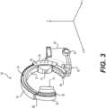
- the system 10 provides a large range of motion in all 6-degrees of freedom ("DOF"). Under the control of the motion control module 51, there are two main modes of motion: positioning of the movable station 60 and positioning of the gantry 56.
- DOF 6-degrees of freedom
- the movable station 60 positioning is accomplished via the four omni-directional wheels 62,64. These wheels 62,64 allow the movable station 60 to be positioned in all three DOF about the horizontal plane (X,Y,Wag).
- “Wag” is a system 10 rotation about the vertical axis (Z-axis)
- "X” is a system forward and backward positioning along the X-axis
- "Y” is system 10 lateral motion along the Y-axis.
- the system 10 can be positioned in any combination of X, Y, and Wag (Wag about any arbitrary Z-axis due to use of omnidirectional wheels 62,64) with unlimited range of motion.
- the omni- directional wheels 62,64 allow for positioning in tight spaces, narrow corridors, or for precisely traversing up and down the length of an OR table or patient bed.
- the gantry 56 positioning is accomplished about (Z, Tilt, Rotor).
- Z is gantry 56 vertical positioning
- Tit is rotation about the horizontal axis parallel to the X-axis as described above
- Rotor is rotation about the horizontal axis parallel to the Y-axis as described above.
- the system 10 provides a range of motion in all 6 DOF (X, Y, Wag, Z, Tilt and Rotor) to place the movable station 60 and the imaging transmitter 74 and sensor 76 precisely where they are needed.
- 6 DOF X, Y, Wag, Z, Tilt and Rotor
- 3-D imaging can be performed regardless of whether the patient is standing up, sitting up or lying in bed and without having to move the patient.
- Precise positions of the system 10 can be stored in the storage memory 50 and recalled at any time by the motion control module 51. This is not limited to gantry 56 positioning but also includes system 10 positioning due to the omni-directional wheels 62,64.
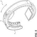
- each of the gantry mount 58, outer C-arm 70 and inner C-arm 72 respectively has a pair of side frames 86, 88,90 that face each other.
- a plurality of uniformly spaced rollers 84 are mounted on the inner sides of the side frames 86 of the gantry mount 58.
- the outer C-arm 70 has a pair of guide rails 78 on the outer sides of the side frames 88.
- the rollers 84 are coupled to the guide rails 78.
- rollers 84 and the guide rails 78 are designed to allow the outer C-arm 78 to telescopically slide along the gantry mount 58 so as to allow at least 180 degree rotation of the C-arm about its central axis relative to the gantry mount.
- a plurality of uniformly spaced rollers 80 are mounted on the inner sides of the side frames 88 of the outer C-arm 70.
- the inner C-arm 72 has a pair of guide rails 82 on the outer sides of the side frames 90.
- the rollers 80 are coupled to the guide rails 82.
- the rollers 80 and the guide rails 82 are designed to allow the inner C-arm 72 to telescopically slide along the outer C-arm 70 so as to allow at least 180 degree rotation of the C-arm about its central axis relative to the outer C-arm.
- the present invention as disclosed herein advantageously allows the gantry 56 to rotate about its central axis a full 360 degrees to provide the maximum flexibility in positioning the imaging system 10 with minimum disturbance of the patient.
- a unique cabling arrangement is provided to make the imaging system 10 more compact and visually more appealing.
- a cable carrier/harness 92 contains electrical cables to carry signals between the imaging controller system 40 and various motors, X-ray transmitter 74, imaging sensor 76 and various electronic circuits in the gantry 56.
- a first cable router 94 is mounted to the outer surface of the outer C-arm 70 and a second cable router 96 is mounted to the outer surface of the inner C-arm 72.
- Each cable router 94,96 has a through-hole 95,97 through which the cable carrier 92 passes.
- the cable carrier 92 extends from the gantry mount 56 over the outer surface of the first C-arm 70, through the through-hole 95 of the first cable router 94 and over an outer surface of the second C-arm 72.
- the cable carrier 92 overlying the first C-arm 70 extends in a first circumferential direction (clock-wise as shown) 98 and enters the first cable router 94 in a second circumferential direction (counter clock-wise as shown) 99 opposite to the first circumferential direction to create a 180 degree service loop over the outer surface of the first C-arm.
- the cable carrier 92 extends in the first circumferential direction 98 and enters the second cable router in the second circumferential direction 99 to create another service loop over the outer surface of the second C-arm 72.
- first and second cable routers 94,96 combined with the service loops allow slack in the cable carrier 92 to provide the gantry 56 with full 360 degrees rotation without tangling or causing stress in the cable carrier.
- the routers are mounted near the midpoint of the C-arms.
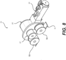
- FIG. 8 illustrates one embodiment of a motor assembly 101 that could be used to telescopically rotate the outer C-arm 70 relative to the gantry mount 58 and inner C-arm 72 relative to the outer C-arm.
- Each motor assembly 101 includes a servo motor 103 with encoder feedback, gear box 105 to change the turning ratio, drive pulley 107, idler pulleys 108 and belt 111 threaded between the drive pulley and the idler pulleys.
- One motor assembly 101 is mounted to the gantry mount to move the outer C-arm 70 relative to the gantry mount and another motor assembly is mounted to the outer C-arm 70 near the center of the arm to move the inner C-arm 70 relative to the outer C-arm.
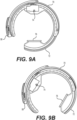
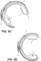
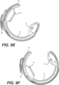
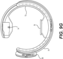
- FIGS. 9A-9G illustrate the 360 degree rotation of the gantry 56 in the counter-clockwise direction in 60 degree increments with FIG. 9A representing a zero degree position of the imaging sensor 76 and transmitter 74.
- FIG. 9B represents a 60 degree turn/position of the gantry 56.
- the motor assemblies 101 under the control of the motion control module 51, turn the inner C-arm 72 by 30 degrees counter-clock wise and also turn the outer C-arm 70 by 30 degrees counter-clock wise for a combined 60 degree turn.
- FIG. 9G represents a full 360 degree turn of the gantry 56. As can be seen, the outer C-arm 70 and inner C-arm 72 have each moved 180 degrees from the original zero degree position of FIG. 9A .
- the present invention in various embodiments provide the following benefits: (1) movement of the system in any X-Y direction with Wag about any Z-axis from the use of omni-directional wheels 62,64; (2) double telescoping C-gantry for full 360-degree imaging beam rotation; (3) imaging while lying in bed, sitting or standing such as standing CBCT; (4) storage and recall of system 10 and gantry 56 positions; (5) quasi-simultaneous multi-planar x-ray imaging; (6) recall of positions via robotics or navigation coordinates.
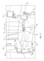
- FIGS. 10 and 11 illustrate a surgical robot system 100 in accordance with an exemplary embodiment.
- Surgical robot system 100 may include, for example, a surgical robot 102, one or more robot arms 104, a base 106, a display 110, an end-effector 112, for example, including a guide tube 114, and one or more tracking markers 118.
- the surgical robot system 100 may include a patient tracking device 116 also including one or more tracking markers 118, which is adapted to be secured directly to the patient 210 (e.g., to the bone of the patient 210).
- the surgical robot system 100 may also utilize a camera 200, for example, positioned on a camera stand 202.
- the camera stand 202 can have any suitable configuration to move, orient, and support the camera 200 in a desired position.
- the camera 200 may include any suitable camera or cameras, such as one or more infrared cameras (e.g., bifocal or stereophotogrammetric cameras), able to identify, for example, active and passive tracking markers 118 in a given measurement volume viewable from the perspective of the camera 200.
- the camera 200 may scan the given measurement volume and detect the light that comes from the markers 118 in order to identify and determine the position of the markers 118 in three-dimensions.
- active markers 118 may include infrared-emitting markers that are activated by an electrical signal (e.g., infrared light emitting diodes (LEDs)), and passive markers 118 may include retro-reflective markers that reflect infrared light (e.g., they reflect incoming IR radiation into the direction of the incoming light), for example, emitted by illuminators on the camera 200 or other suitable device.
- LEDs infrared light emitting diodes
- FIGS. 10 and 11 illustrate a potential configuration for the placement of the surgical robot system 100 in an operating room environment.
- the robot 102 may be positioned near or next to patient 210. Although depicted near the head of the patient 210, it will be appreciated that the robot 102 can be positioned at any suitable location near the patient 210 depending on the area of the patient 210 undergoing the operation.
- the camera 200 may be separated from the robot system 100 and positioned at the foot of patient 210. This location allows the camera 200 to have a direct visual line of sight to the surgical field 208. Again, it is contemplated that the camera 200 may be located at any suitable position having line of sight to the surgical field 208.
- the surgeon 120 may be positioned across from the robot 102, but is still able to manipulate the end-effector 112 and the display 110.
- a surgical assistant 126 may be positioned across from the surgeon 120 again with access to both the end-effector 112 and the display 110. If desired, the locations of the surgeon 120 and the assistant 126 may be reversed. The traditional areas for the anesthesiologist 122 and the nurse or scrub tech 124 remain unimpeded by the locations of the robot 102 and camera 200.
- the display 110 can be attached to the surgical robot 102 and in other exemplary embodiments, display 110 can be detached from surgical robot 102, either within a surgical room with the surgical robot 102, or in a remote location.
- End-effector 112 may be coupled to the robot arm 104 and controlled by at least one motor.
- end-effector 112 can comprise a guide tube 114, which is able to receive and orient a surgical instrument 608 (described further herein) used to perform surgery on the patient 210.
- end-effector is used interchangeably with the terms “end-effectuator” and “effectuator element.”
- end-effector 112 may be replaced with any suitable instrumentation suitable for use in surgery.
- end-effector 112 can comprise any known structure for effecting the movement of the surgical instrument 608 in a desired manner.
- the surgical robot 102 is able to control the translation and orientation of the end-effector 112.
- the robot 102 is able to move end-effector 112 along x-, y-, and z-axes, for example.
- the end-effector 112 can be configured for selective rotation about one or more of the x-, y-, and z-axis , and a Z Frame axis (such that one or more of the Euler Angles (e.g., roll, pitch, and/or yaw) associated with end-effector 112 can be selectively controlled).
- selective control of the translation and orientation of end-effector 112 can permit performance of medical procedures with significantly improved accuracy compared to conventional robots that utilize, for example, a six degree of freedom robot arm comprising only rotational axes.
- the surgical robot system 100 may be used to operate on patient 210, and robot arm 104 can be positioned above the body of patient 210, with end-effector 112 selectively angled relative to the z-axis toward the body of patient 210.
- the position of the surgical instrument 608 can be dynamically updated so that surgical robot 102 can be aware of the location of the surgical instrument 608 at all times during the procedure. Consequently, in some exemplary embodiments, surgical robot 102 can move the surgical instrument 608 to the desired position quickly without any further assistance from a physician (unless the physician so desires). In some further embodiments, surgical robot 102 can be configured to correct the path of the surgical instrument 608 if the surgical instrument 608 strays from the selected, preplanned trajectory. In some exemplary embodiments, surgical robot 102 can be configured to permit stoppage, modification, and/or manual control of the movement of end-effector 112 and/or the surgical instrument 608.
- a physician or other user can operate the system 100, and has the option to stop, modify, or manually control the autonomous movement of end-effector 112 and/or the surgical instrument 608.
- Further details of surgical robot system 100 including the control and movement of a surgical instrument 608 by surgical robot 102 can be found in co-pending U.S. patent application Ser. No. 13/924,505 , which is incorporated herein by reference in its entirety.
- the robotic surgical system 100 can comprise one or more tracking markers 118 configured to track the movement of robot arm 104, end-effector 112, patient 210, and/or the surgical instrument 608 in three dimensions.
- a plurality of tracking markers 118 can be mounted (or otherwise secured) thereon to an outer surface of the robot 102, such as, for example and without limitation, on base 106 of robot 102, on robot arm 104, or on the end-effector 112.
- at least one tracking marker 118 of the plurality of tracking markers 118 can be mounted or otherwise secured to the end-effector 112.
- One or more tracking markers 118 can further be mounted (or otherwise secured) to the patient 210.
- the plurality of tracking markers 118 can be positioned on the patient 210 spaced apart from the surgical field 208 to reduce the likelihood of being obscured by the surgeon, surgical tools, or other parts of the robot 102. Further, one or more tracking markers 118 can be further mounted (or otherwise secured) to the surgical tools 608 (e.g., a screw driver, dilator, implant inserter, or the like). Thus, the tracking markers 118 enable each of the marked objects (e.g., the end-effector 112, the patient 210, and the surgical tools 608) to be tracked by the robot 102.
- the marked objects e.g., the end-effector 112, the patient 210, and the surgical tools 608
- system 100 can use tracking information collected from each of the marked objects to calculate the orientation and location, for example, of the end-effector 112, the surgical instrument 608 (e.g., positioned in the tube 114 of the end-effector 112), and the relative position of the patient 210.
- one or more of markers 118 may be optical markers.
- the positioning of one or more tracking markers 118 on end-effector 112 can maximize the accuracy of the positional measurements by serving to check or verify the position of end-effector 112. Further details of surgical robot system 100 including the control, movement and tracking of surgical robot 102 and of a surgical instrument 608 can be found in co-pending U.S. patent application Ser. No. 13/924,505 , which is incorporated herein by reference in its entirety.
- Exemplary embodiments include one or more markers 118 coupled to the surgical instrument 608.
- these markers 118 for example, coupled to the patient 210 and surgical instruments 608, as well as markers 118 coupled to the end-effector 112 of the robot 102 can comprise conventional infrared light-emitting diodes (LEDs) or an Optotrak ® diode capable of being tracked using a commercially available infrared optical tracking system such as Optotrak ® .
- Optotrak ® is a registered trademark of Northern Digital Inc., Waterloo, Ontario, Canada.
- markers 118 can comprise conventional reflective spheres capable of being tracked using a commercially available optical tracking system such as Polaris Spectra.
- the markers 118 coupled to the end-effector 112 are active markers which comprise infrared light-emitting diodes which may be turned on and off, and the markers 118 coupled to the patient 210 and the surgical instruments 608 comprise passive reflective spheres.
- markers 118 can comprise a radio-frequency and/or electromagnetic reflector or transceiver and the camera 200 can include or be replaced by a radio-frequency and/or electromagnetic transceiver.
- FIG. 12 illustrates a surgical robot system 300 and camera stand 302, in a docked configuration, consistent with an exemplary embodiment of the present disclosure.
- Surgical robot system 300 may comprise a robot 301 including a display 304, upper arm 306, lower arm 308, end-effector 310, vertical column 312, casters 314, cabinet 316, tablet drawer 318, connector panel 320, control panel 322, and ring of information 324.
- Camera stand 302 may comprise camera 326. These components are described in greater with respect to FIG. 14 .
- FIG. 12 illustrates the surgical robot system 300 in a docked configuration where the camera stand 302 is nested with the robot 301, for example, when not in use. It will be appreciated by those skilled in the art that the camera 326 and robot 301 may be separated from one another and positioned at any appropriate location during the surgical procedure, for example, as shown in FIGS. 10 and 11 .
- FIG. 13 illustrates a base 400 consistent with an exemplary embodiment of the present disclosure.
- Base 400 may be a portion of surgical robot system 300 and comprise cabinet 316.
- Cabinet 316 may house certain components of surgical robot system 300 including but not limited to a battery 402, a power distribution module 404, a platform interface board module 406, a computer 408, a handle 412, and a tablet drawer 414. The connections and relationship between these components is described in greater detail with respect to FIG. 14 .
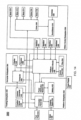
- FIG. 14 illustrates a block diagram of certain components of an exemplary embodiment of surgical robot system 300.
- Surgical robot system 300 may comprise platform subsystem 502, computer subsystem 504, motion control subsystem 506, and tracking subsystem 532.
- Platform subsystem 502 may further comprise battery 402, power distribution module 404, platform interface board module 406, and tablet charging station 534.
- Computer subsystem 504 may further comprise computer 408, display 304, and speaker 536.
- Motion control subsystem 506 may further comprise driver circuit 508, motors 510, 512, 514, 516, 518, stabilizers 520, 522, 524, 526, end-effector 310, and controller 538.
- Tracking subsystem 532 may further comprise position sensor 540 and camera converter 542.
- System 300 may also comprise a foot pedal 544 and tablet 546.
- Input power is supplied to system 300 via a power source 548 which may be provided to power distribution module 404.
- Power distribution module 404 receives input power and is configured to generate different power supply voltages that are provided to other modules, components, and subsystems of system 300.
- Power distribution module 404 may be configured to provide different voltage supplies to platform interface module 406, which may be provided to other components such as computer 408, display 304, speaker 536, driver 508 to, for example, power motors 512, 514, 516, 518 and end-effector 310, motor 510, ring 324, camera converter 542, and other components for system 300 for example, fans for cooling the electrical components within cabinet 316.
- Power distribution module 404 may also provide power to other components such as tablet charging station 534 that may be located within tablet drawer 318.
- Tablet charging station 534 may be in wireless or wired communication with tablet 546 for charging table 546.
- Tablet 546 may be used by a surgeon consistent with the present disclosure and described herein.
- Power distribution module 404 may also be connected to battery 402, which serves as temporary power source in the event that power distribution module 404 does not receive power from input power 548. At other times, power distribution module 404 may serve to charge battery 402 if necessary.
- Connector panel 320 may serve to connect different devices and components to system 300 and/or associated components and modules.
- Connector panel 320 may contain one or more ports that receive lines or connections from different components.
- connector panel 320 may have a ground terminal port that may ground system 300 to other equipment, a port to connect foot pedal 544 to system 300, a port to connect to tracking subsystem 532, which may comprise position sensor 540, camera converter 542, and cameras 326 associated with camera stand 302.
- Connector panel 320 may also include other ports to allow USB, Ethernet, HDMI communications to other components, such as computer 408.
- Control panel 322 may provide various buttons or indicators that control operation of system 300 and/or provide information regarding system 300.
- control panel 322 may include buttons to power on or off system 300, lift or lower vertical column 312, and lift or lower stabilizers 520-526 that may be designed to engage casters 314 to lock system 300 from physically moving.
- Other buttons may stop system 300 in the event of an emergency, which may remove all motor power and apply mechanical brakes to stop all motion from occurring.
- Control panel 322 may also have indicators notifying the user of certain system conditions such as a line power indicator or status of charge for battery 402.
- Ring 324 may be a visual indicator to notify the user of system 300 of different modes that system 300 is operating under and certain warnings to the user.
- Computer subsystem 504 includes computer 408, display 304, and speaker 536.
- Computer 504 includes an operating system and software to operate system 300.
- Computer 504 may receive and process information from other components (for example, tracking subsystem 532, platform subsystem 502, and/or motion control subsystem 506) in order to display information to the user.
- computer subsystem 504 may also include speaker 536 to provide audio to the user.
- Tracking subsystem 532 may include position sensor 504 and converter 542. Tracking subsystem 532 may correspond to camera stand 302 including camera 326 as described with respect to FIG. 12 . Position sensor 504 may be camera 326. Tracking subsystem may track the location of certain markers that are located on the different components of system 300 and/or instruments used by a user during a surgical procedure. This tracking may be conducted in a manner consistent with the present disclosure including the use of infrared technology that tracks the location of active or passive elements, such as LEDs or reflective markers, respectively. The location, orientation, and position of structures having these types of markers may be provided to computer 408 which may be shown to a user on display 304. For example, a surgical instrument 608 having these types of markers and tracked in this manner (which may be referred to as a navigational space) may be shown to a user in relation to a three dimensional image of a patient's anatomical structure.
- Motion control subsystem 506 may be configured to physically move vertical column 312, upper arm 306, lower arm 308, or rotate end-effector 310.
- the physical movement may be conducted through the use of one or more motors 510-518.
- motor 510 may be configured to vertically lift or lower vertical column 312.
- Motor 512 may be configured to laterally move upper arm 308 around a point of engagement with vertical column 312 as shown in FIG. 12 .
- Motor 514 may be configured to laterally move lower arm 308 around a point of engagement with upper arm 308 as shown in FIG. 12 .
- Motors 516 and 518 may be configured to move end-effector 310 in a manner such that one may control the roll and one may control the tilt, thereby providing multiple angles that end-effector 310 may be moved. These movements may be achieved by controller 538 which may control these movements through load cells disposed on end-effector 310 and activated by a user engaging these load cells to move system 300 in a desired manner.
- system 300 may provide for automatic movement of vertical column 312, upper arm 306, and lower arm 308 through a user indicating on display 304 (which may be a touchscreen input device) the location of a surgical instrument or component on three dimensional image of the patient's anatomy on display 304.
- the user may initiate this automatic movement by stepping on foot pedal 544 or some other input means.
- FIG. 15 illustrates a surgical robot system 600 consistent with an exemplary embodiment.
- Surgical robot system 600 may comprise end-effector 602, robot arm 604, guide tube 606, instrument 608, and robot base 610.
- Instrument tool 608 may be attached to a tracking array 612 including one or more tracking markers (such as markers 118) and have an associated trajectory 614.
- Trajectory 614 may represent a path of movement that instrument tool 608 is configured to travel once it is positioned through or secured in guide tube 606, for example, a path of insertion of instrument tool 608 into a patient.
- robot base 610 may be configured to be in electronic communication with robot arm 604 and end-effector 602 so that surgical robot system 600 may assist a user (for example, a surgeon) in operating on the patient 210.
- Surgical robot system 600 may be consistent with previously described surgical robot system 100 and 300.
- a tracking array 612 may be mounted on instrument 608 to monitor the location and orientation of instrument tool 608.
- the tracking array 612 may be attached to an instrument 608 and may comprise tracking markers 804.
- tracking markers 804 may be, for example, light emitting diodes and/or other types of reflective markers (e.g., markers 118 as described elsewhere herein).
- the tracking devices may be one or more line of sight devices associated with the surgical robot system.
- the tracking devices may be one or more cameras 200, 326 associated with the surgical robot system 100, 300 and may also track tracking array 612 for a defined domain or relative orientations of the instrument 608 in relation to the robot arm 604, the robot base 610, end-effector 602, and/or the patient 210.
- the tracking devices may be consistent with those structures described in connection with camera stand 302 and tracking subsystem 532.
- FIGS. 16A, 16B, and 16C illustrate a top view, front view, and side view, respectively, of end-effector 602 consistent with an exemplary embodiment.
- End-effector 602 may comprise one or more tracking markers 702.
- Tracking markers 702 may be light emitting diodes or other types of active and passive markers, such as tracking markers 118 that have been previously described.
- the tracking markers 702 are active infrared-emitting markers that are activated by an electrical signal (e.g., infrared light emitting diodes (LEDs)).
- LEDs infrared light emitting diodes
- tracking markers 702 may be activated such that the infrared markers 702 are visible to the camera 200, 326 or may be deactivated such that the infrared markers 702 are not visible to the camera 200, 326.
- the end-effector 602 may be controlled by the system 100, 300, 600, and when the markers 702 are deactivated, the end-effector 602 may be locked in position and unable to be moved by the system 100, 300, 600.
- Markers 702 may be disposed on or within end-effector 602 in a manner such that the markers 702 are visible by one or more cameras 200, 326 or other tracking devices associated with the surgical robot system 100, 300, 600.
- the camera 200, 326 or other tracking devices may track end-effector 602 as it moves to different positions and viewing angles by following the movement of tracking markers 702.
- the location of markers 702 and/or end-effector 602 may be shown on a display 110, 304 associated with the surgical robot system 100, 300, 600, for example, display 110 as shown in FIG. 11 and/or display 304 shown in FIG. 12 .
- This display 110, 304 may allow a user to ensure that end-effector 602 is in a desirable position in relation to robot arm 604, robot base 610, the patient 210, and/or the user.
- markers 702 may be placed around the surface of end-effector 602 so that a tracking device placed away from the surgical field 208 and facing toward the robot 102, 301 and the camera 200, 326 is able to view at least 3 of the markers 702 through a range of common orientations of the end-effector 602 relative to the tracking device 100, 300, 600.
- distribution of markers 702 in this way allows end-effector 602 to be monitored by the tracking devices when end-effector 602 is translated and rotated in the surgical field 208.
- end-effector 602 may be equipped with infrared (IR) receivers that can detect when an external camera 200, 326 is getting ready to read markers 702. Upon this detection, end-effector 602 may then illuminate markers 702.
- IR infrared
- the detection by the IR receivers that the external camera200, 326 is ready to read markers 702 may signal the need to synchronize a duty cycle of markers 702, which may be light emitting diodes, to an external camera200, 326. This may also allow for lower power consumption by the robotic system as a whole, whereby markers 702 would only be illuminated at the appropriate time instead of being illuminated continuously.
- markers 702 may be powered off to prevent interference with other navigation tools, such as different types of surgical instruments 608.
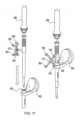
- FIG. 17 depicts one type of surgical instrument 608 including a tracking array 612 and tracking markers 804.
- Tracking markers 804 may be of any type described herein including but not limited to light emitting diodes or reflective spheres. Markers 804 are monitored by tracking devices associated with the surgical robot system 100, 300, 600 and may be one or more of the line of sight cameras 200, 326. The cameras 200, 326 may track the location of instrument 608 based on the position and orientation of tracking array 612 and markers 804. A user, such as a surgeon 120, may orient instrument 608 in a manner so that tracking array 612 and markers 804 are sufficiently recognized by the tracking device or camera 200, 326 to display instrument 608 and markers 804 on, for example, display 110 of the exemplary surgical robot system.
- the manner in which a surgeon 120 may place instrument 608 into guide tube 606 of the end-effector 602 and adjust the instrument 608 is evident in FIG. 17 .
- the hollow tube or guide tube 114, 606 of the end-effector 112, 310, 602 is sized and configured to receive at least a portion of the surgical instrument 608.
- the guide tube 114, 606 is configured to be oriented by the robot arm 104 such that insertion and trajectory for the surgical instrument 608 is able to reach a desired anatomical target within or upon the body of the patient 210.
- the surgical instrument 608 may include at least a portion of a generally cylindrical instrument.
- the surgical instrument 608 may include one or more of a guide wire, cannula, a retractor, a drill, a reamer, a screw driver, an insertion tool, a removal tool, or the like.
- the hollow tube 114, 606 is generally shown as having a cylindrical configuration, it will be appreciated by those of skill in the art that the guide tube 114, 606 may have any suitable shape, size and configuration desired to accommodate the surgical instrument 608 and access the surgical site.
- FIGS. 18A-18C illustrate end-effector 602 and a portion of robot arm 604 consistent with an exemplary embodiment.
- End-effector 602 may further comprise body 1202 and clamp 1204.
- Clamp 1204 may comprise handle 1206, balls 1208, spring 1210, and lip 1212.
- Robot arm 604 may further comprise depressions 1214, mounting plate 1216, lip 1218, and magnets 1220.
- End-effector 602 may mechanically interface and/or engage with the surgical robot system and robot arm 604 through one or more couplings.
- end-effector 602 may engage with robot arm 604 through a locating coupling and/or a reinforcing coupling. Through these couplings, end-effector 602 may fasten with robot arm 604 outside a flexible and sterile barrier.
- the locating coupling may be a magnetically kinematic mount and the reinforcing coupling may be a five bar over center clamping linkage.
- robot arm 604 may comprise mounting plate 1216, which may be non-magnetic material, one or more depressions 1214, lip 1218, and magnets 1220.
- Magnet 1220 is mounted below each of depressions 1214.
- Portions of clamp 1204 may comprise magnetic material and be attracted by one or more magnets 1220.
- balls 1208 become seated into respective depressions 1214.
- balls 1208 as shown in FIG. 18B would be seated in depressions 1214 as shown in FIG. 18A .
- This seating may be considered a magnetically-assisted kinematic coupling.
- Magnets 1220 may be configured to be strong enough to support the entire weight of end-effector 602 regardless of the orientation of end-effector 602.
- the locating coupling may be any style of kinematic mount that uniquely restrains six degrees of freedom.
- portions of clamp 1204 may be configured to be a fixed ground link and as such clamp 1204 may serve as a five bar linkage.
- Closing clamp handle 1206 may fasten end-effector 602 to robot arm 604 as lip 1212 and lip 1218 engage clamp 1204 in a manner to secure end-effector 602 and robot arm 604.
- spring 1210 may be stretched or stressed while clamp 1204 is in a locked position.
- the locked position may be a position that provides for linkage past center. Because of a closed position that is past center, the linkage will not open absent a force applied to clamp handle 1206 to release clamp 1204. Thus, in a locked position end-effector 602 may be robustly secured to robot arm 604.
- Spring 1210 may be a curved beam in tension.
- Spring 1210 may be comprised of a material that exhibits high stiffness and high yield strain such as virgin PEEK (poly-ether-etherketone).
- the linkage between end-effector 602 and robot arm 604 may provide for a sterile barrier between end-effector 602 and robot arm 604 without impeding fastening of the two couplings.
- the reinforcing coupling may be a linkage with multiple spring members.
- the reinforcing coupling may latch with a cam or friction based mechanism.
- the reinforcing coupling may also be a sufficiently powerful electromagnet that will support fastening end-effector 102 to robot arm 604.
- the reinforcing coupling may be a multi-piece collar completely separate from either end-effector 602 and/or robot arm 604 that slips over an interface between end-effector 602 and robot arm 604 and tightens with a screw mechanism, an over center linkage, or a cam mechanism.
- a registration system 1400 may be used as illustrated in FIG. 19 .
- a patient tracking device 116 may include a patient fixation instrument 1402 to be secured to a rigid anatomical structure of the patient 210 and a dynamic reference base (DRB) 1404 may be securely attached to the patient fixation instrument 1402.
- DRB dynamic reference base
- patient fixation instrument 1402 may be inserted into opening 1406 of dynamic reference base 1404.
- Dynamic reference base 1404 may contain markers 1408 that are visible to tracking devices, such as tracking subsystem 532. These markers 1408 may be optical markers or reflective spheres, such as tracking markers 118, as previously discussed herein.
- Patient fixation instrument 1402 is attached to a rigid anatomy of the patient 210 and may remain attached throughout the surgical procedure.
- patient fixation instrument 1402 is attached to a rigid area of the patient 210, for example, a bone that is located away from the targeted anatomical structure subject to the surgical procedure.
- dynamic reference base 1404 is associated with the targeted anatomical structure through the use of a registration fixture that is temporarily placed on or near the targeted anatomical structure in order to register the dynamic reference base 1404 with the location of the targeted anatomical structure.
- a registration fixture 1410 is attached to patient fixation instrument 1402 through the use of a pivot arm 1412.
- Pivot arm 1412 is attached to patient fixation instrument 1402 by inserting patient fixation instrument 1402 through an opening 1414 of registration fixture 1410.
- Pivot arm 1412 is attached to registration fixture 1410 by, for example, inserting a knob 1416 through an opening 1418 of pivot arm 1412.
- registration fixture 1410 may be placed over the targeted anatomical structure and its location may be determined in an image space and navigation space using tracking markers 1420 and/or fiducials 1422 on registration fixture 1410.
- Registration fixture 1410 may contain a collection of markers 1420 that are visible in a navigational space (for example, markers 1420 may be detectable by tracking subsystem 532).
- Tracking markers 1420 may be optical markers visible in infrared light as previously described herein.
- Registration fixture 1410 may also contain a collection of fiducials 1422, for example, such as bearing balls, that are visible in an imaging space (for example, a three dimension CT image). As described in greater detail with respect to FIG.
- the targeted anatomical structure may be associated with dynamic reference base 1404 thereby allowing depictions of objects in the navigational space to be overlaid on images of the anatomical structure.
- Dynamic reference base 1404 located at a position away from the targeted anatomical structure, may become a reference point thereby allowing removal of registration fixture 1410 and/or pivot arm 1412 from the surgical area.
- FIG. 20 provides an exemplary method 1500 for registration consistent with the present disclosure.
- Method 1500 begins at step 1502 wherein a graphical representation (or image(s)) of the targeted anatomical structure may be imported into system 100, 300 600, for example computer 408.
- the graphical representation may be three dimensional CT or a fluoroscope scan of the targeted anatomical structure of the patient 210 which includes registration fixture 1410 and a detectable imaging pattern of fiducials 1420.
- an imaging pattern of fiducials 1420 is detected and registered in the imaging space and stored in computer 408.
- a graphical representation of the registration fixture 1410 may be overlaid on the images of the targeted anatomical structure.
- a navigational pattern of registration fixture 1410 is detected and registered by recognizing markers 1420.
- Markers 1420 may be optical markers that are recognized in the navigation space through infrared light by tracking subsystem 532 via position sensor 540.
- registration fixture 1410 may be recognized in both the image space through the use of fiducials 1422 and the navigation space through the use of markers 1420.
- the registration of registration fixture 1410 in the image space is transferred to the navigation space. This transferal is done, for example, by using the relative position of the imaging pattern of fiducials 1422 compared to the position of the navigation pattern of markers 1420.
- registration of the navigation space of registration fixture 1410 (having been registered with the image space) is further transferred to the navigation space of dynamic registration array 1404 attached to patient fixture instrument 1402.
- registration fixture 1410 may be removed and dynamic reference base 1404 may be used to track the targeted anatomical structure in both the navigation and image space because the navigation space is associated with the image space.
- the navigation space may be overlaid on the image space and objects with markers visible in the navigation space (for example, surgical instruments 608 with optical markers 804).
- the objects may be tracked through graphical representations of the surgical instrument 608 on the images of the targeted anatomical structure.
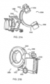
- FIGS. 21A-21B illustrate imaging devices 1304 that may be used in conjunction with robot systems 100, 300, 600 to acquire pre-operative, intra-operative, post-operative, and/or real-time image data of patient 210. Any appropriate subject matter may be imaged for any appropriate procedure using the imaging system 1304.
- the imaging system 1304 may be any imaging device such as imaging device 1306 and/or a C-arm 1308 device. It may be desirable to take x-rays of patient 210 from a number of different positions, without the need for frequent manual repositioning of patient 210 which may be required in an x-ray system. As illustrated in FIG.
- the imaging system 1304 may be in the form of a C-arm 1308 that includes an elongated C-shaped member terminating in opposing distal ends 1312 of the "C" shape.
- C-shaped member 1130 may further comprise an x-ray source 1314 and an image receptor 1316.
- the space within C-arm 1308 of the arm may provide room for the physician to attend to the patient substantially free of interference from x-ray support structure 1318.
- the imaging system may include imaging device 1306 having a gantry housing 1324 attached to a support structure imaging device support structure 1328, such as a wheeled mobile cart 1330 with wheels 1332, which may enclose an image capturing portion, not illustrated.
- the image capturing portion may include an x-ray source and/or emission portion and an x-ray receiving and/or image receiving portion, which may be disposed about one hundred and eighty degrees from each other and mounted on a rotor (not illustrated) relative to a track of the image capturing portion.
- the image capturing portion may be operable to rotate three hundred and sixty degrees during image acquisition.
- the image capturing portion may rotate around a central point and/or axis, allowing image data of patient 210 to be acquired from multiple directions or in multiple planes.
- the surgical robot system 100, 300, 600 relies on accurate positioning of the end-effector 112, 602, surgical instruments 608, and/or the patient 210 (e.g., patient tracking device 116) relative to the desired surgical area.
- the tracking markers 118, 804 are rigidly attached to a portion of the instrument 608 and/or end-effector 112.
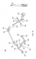
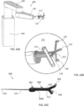
- FIG. 22A depicts part of the surgical robot system 100 with the robot 102 including base 106, robot arm 104, and end-effector 112.
- the other elements, not illustrated, such as the display, cameras, etc. may also be present as described herein.
- FIG. 22B depicts a close-up view of the end-effector 112 with guide tube 114 and a plurality of tracking markers 118 rigidly affixed to the end-effector 112. In this embodiment, the plurality of tracking markers 118 are attached to the guide tube 112.
- FIG. 22C depicts an instrument 608 (in this case, a probe 608A) with a plurality of tracking markers 804 rigidly affixed to the instrument 608.
- the instrument 608 could include any suitable surgical instrument, such as, but not limited to, guide wire, cannula, a retractor, a drill, a reamer, a screw driver, an insertion tool, a removal tool, or the like.
- an array of tracking markers 118, 804 may be rigidly attached to a portion of the tool 608 or end-effector 112.
- the tracking markers 118, 804 are attached such that the markers 118, 804 are out of the way (e.g., not impeding the surgical operation, visibility, etc.).
- the markers 118, 804 may be affixed to the instrument 608, end-effector 112, or other object to be tracked, for example, with an array 612.
- the array 612 may include a linear section, a cross piece, and may be asymmetric such that the markers 118, 804 are at different relative positions and locations with respect to one another.
- FIG. 22C a probe 608A with a 4-marker tracking array 612 is shown, and FIG. 22B depicts the end-effector 112 with a different 4-marker tracking array 612.
- the tracking array 612 functions as the handle 620 of the probe 608A.
- the four markers 804 are attached to the handle 620 of the probe 608A, which is out of the way of the shaft 622 and tip 624. Stereophotogrammetric tracking of these four markers 804 allows the instrument 608 to be tracked as a rigid body and for the tracking system 100, 300, 600 to precisely determine the position of the tip 624 and the orientation of the shaft 622 while the probe 608A is moved around in front of tracking cameras 200, 326.
- the markers 118, 804 on each tool 608, end-effector 112, or the like are arranged asymmetrically with a known inter-marker spacing.
- the reason for asymmetric alignment is so that it is unambiguous which marker 118, 804 corresponds to a particular location on the rigid body and whether markers 118, 804 are being viewed from the front or back, i.e., mirrored.
- each array 612 and thus each tool 608, end-effector 112, or other object to be tracked should have a unique marker pattern to allow it to be distinguished from other tools 608 or other objects being tracked.
- Asymmetry and unique marker patterns allow the system 100, 300, 600 to detect individual markers 118, 804 then to check the marker spacing against a stored template to determine which tool 608, end effector 112, or other object they represent. Detected markers 118, 804 can then be sorted automatically and assigned to each tracked object in the correct order. Without this information, rigid body calculations could not then be performed to extract key geometric information, for example, such as tool tip 624 and alignment of the shaft 622, unless the user manually specified which detected marker 118, 804 corresponded to which position on each rigid body. These concepts are commonly known to those skilled in the methods of 3D optical tracking.
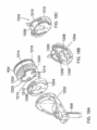
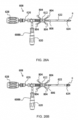
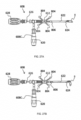
- FIGS. 23A-23D an alternative version of an end-effector 912 with moveable tracking markers 918A-918D is shown.
- FIG. 23A an array with moveable tracking markers 918A-918D are shown in a first configuration
- FIG. 23B the moveable tracking markers 918A-918D are shown in a second configuration, which is angled relative to the first configuration.
- FIG. 23C shows the template of the tracking markers 918A-918D, for example, as seen by the cameras 200, 326 in the first configuration of FIG. 23A
- FIG. 23D shows the template of tracking markers 918A-918D, for example, as seen by the cameras 200, 326 in the second configuration of FIG. 23B .
- 4-marker array tracking is contemplated wherein the markers 918A-918D are not all in fixed position relative to the rigid body and instead, one or more of the array markers 918A-918D can be adjusted, for example, during testing, to give updated information about the rigid body that is being tracked without disrupting the process for automatic detection and sorting of the tracked markers 918A-918D.
- the tracking array's primary purpose is to update the position of the end effector 912 in the camera coordinate system.
- the array 612 of reflective markers 118 rigidly extend from the guide tube 114. Because the tracking markers 118 are rigidly connected, knowledge of the marker locations in the camera coordinate system also provides exact location of the centerline, tip, and tail of the guide tube 114 in the camera coordinate system.
- information about the position of the end effector 112 from such an array 612 and information about the location of a target trajectory from another tracked source are used to calculate the required moves that must be input for each axis of the robot 102 that will move the guide tube 114 into alignment with the trajectory and move the tip to a particular location along the trajectory vector.
- the desired trajectory is in an awkward or unreachable location, but if the guide tube 114 could be swiveled, it could be reached.
- a very steep trajectory pointing away from the base 106 of the robot 102 might be reachable if the guide tube 114 could be swiveled upward beyond the limit of the pitch (wrist up-down angle) axis, but might not be reachable if the guide tube 114 is attached parallel to the plate connecting it to the end of the wrist.
- the base 106 of the robot 102 might be moved or a different end effector 112 with a different guide tube attachment might be exchanged with the working end effector. Both of these solutions may be time consuming and cumbersome.
- the robot 102 can provide updated information about the object being tracked without disrupting the detection and tracking process.
- one of the markers 918A-918D may be fixed in position and the other markers 918A-918D may be moveable; two of the markers 918A-918D may be fixed in position and the other markers 918A-918D may be moveable; three of the markers 918A-918D may be fixed in position and the other marker 918A-918D may be moveable; or all of the markers 918A-918D may be moveable.
- markers 918A, 918 B are rigidly connected directly to a base 906 of the end-effector 912, and markers 918C, 918D are rigidly connected to the tube 914.
- array 908 may be provided to attach the markers 918A-918D to the end-effector 912, instrument 608, or other object to be tracked.
- the array 908 is comprised of a plurality of separate components.
- markers 918A, 918B may be connected to the base 906 with a first array 908A
- markers 918C, 918D may be connected to the guide tube 914 with a second array 908B.
- Marker 918A may be affixed to a first end of the first array 908A and marker 918B may be separated a linear distance and affixed to a second end of the first array 908A. While first array 908 is substantially linear, second array 908B has a bent or V-shaped configuration, with respective root ends, connected to the guide tube 914, and diverging therefrom to distal ends in a V-shape with marker 918C at one distal end and marker 918D at the other distal end.
- specific configurations are exemplified herein, it will be appreciated that other asymmetric designs including different numbers and types of arrays 908A, 908B and different arrangements, numbers, and types of markers 918A-918D are contemplated.
- the guide tube 914 may be moveable, swivelable, or pivotable relative to the base 906, for example, across a hinge 920 or other connector to the base 906.
- markers 918C, 918D are moveable such that when the guide tube 914 pivots, swivels, or moves, markers 918C, 918D also pivot, swivel, or move.
- guide tube 914 has a longitudinal axis 916 which is aligned in a substantially normal or vertical orientation such that markers 918A-918D have a first configuration.
- FIG. 23B the guide tube 914 is pivoted, swiveled, or moved such that the longitudinal axis 916 is now angled relative to the vertical orientation such that markers 918A-918D have a second configuration, different from the first configuration.
- the robotic system 100, 300, 600 would not be able to automatically detect that the guide tube 914 orientation had changed.
- the robotic system 100, 300, 600 would track the positions of the marker array 908 and would calculate incorrect robot axis moves assuming the guide tube 914 was attached to the wrist (the robot arm 104) in the previous orientation.
- markers 918A-918D e.g., two markers 918C, 918D
- markers 918A-918D e.g., two markers 918A, 918B
- markers 918A-918D are configured to be moved, pivoted, swiveled, or the like according to any suitable means.
- the markers 918A-918D may be moved by a hinge 920, such as a clamp, spring, lever, slide, toggle, or the like, or any other suitable mechanism for moving the markers 918A-918D individually or in combination, moving the arrays 908A, 908B individually or in combination, moving any portion of the end-effector 912 relative to another portion, or moving any portion of the tool 608 relative to another portion.
- the array 908 and guide tube 914 may become reconfigurable by simply loosening the clamp or hinge 920, moving part of the array 908A, 908B relative to the other part 908A, 908B, and retightening the hinge 920 such that the guide tube 914 is oriented in a different position.
- two markers 918C, 918D may be rigidly interconnected with the tube 914 and two markers 918A, 918B may be rigidly interconnected across the hinge 920 to the base 906 of the end-effector 912 that attaches to the robot arm 104.
- the hinge 920 may be in the form of a clamp, such as a wing nut or the like, which can be loosened and retightened to allow the user to quickly switch between the first configuration ( FIG. 23A ) and the second configuration ( FIG. 23B ).
- the cameras 200, 326 detect the markers 918A-918D, for example, in one of the templates identified in FIGS. 23C and 23D . If the array 908 is in the first configuration ( FIG. 23A ) and tracking cameras 200, 326 detect the markers 918A-918D, then the tracked markers match Array Template 1 as shown in FIG. 23C . If the array 908 is the second configuration ( FIG. 23B ) and tracking cameras 200, 326 detect the same markers 918A-918D, then the tracked markers match Array Template 2 as shown in FIG. 23D .
- Array Template 1 and Array Template 2 are recognized by the system 100, 300, 600 as two distinct tools, each with its own uniquely defined spatial relationship between guide tube 914, markers 918A-918D, and robot attachment. The user could therefore adjust the position of the end-effector 912 between the first and second configurations without notifying the system 100, 300, 600 of the change and the system 100, 300, 600 would appropriately adjust the movements of the robot 102 to stay on trajectory.
- the marker array matches unique templates that allow the system 100, 300, 600 to recognize the assembly as two different tools or two different end effectors.
- any position of the swivel between or outside of these two positions namely, Array Template 1 and Array Template 2 shown in FIGS. 23C and 23D , respectively
- the markers 918A-918D would not match any template and the system 100, 300, 600 would not detect any array present despite individual markers 918A-918D being detected by cameras 200, 326, with the result being the same as if the markers 918A-918D were temporarily blocked from view of the cameras 200, 326.
- other array templates may exist for other configurations, for example, identifying different instruments 608 or other end-effectors 112, 912, etc.
- FIGS. 23A and 23B two discrete assembly positions are shown in FIGS. 23A and 23B . It will be appreciated, however, that there could be multiple discrete positions on a swivel joint, linear joint, combination of swivel and linear joints, pegboard, or other assembly where unique marker templates may be created by adjusting the position of one or more markers 918A-918D of the array relative to the others, with each discrete position matching a particular template and defining a unique tool 608 or end-effector 112, 912 with different known attributes.
- end effector 912 it will be appreciated that moveable and fixed markers 918A-918D may be used with any suitable instrument 608 or other object to be tracked.
- an external 3D tracking system 100, 300, 600 When using an external 3D tracking system 100, 300, 600 to track a full rigid body array of three or more markers attached to a robot's end effector 112 (for example, as depicted in FIGS. 22A and 22B ), it is possible to directly track or to calculate the 3D position of every section of the robot 102 in the coordinate system of the cameras 200, 326.
- the geometric orientations of joints relative to the tracker are known by design, and the linear or angular positions of joints are known from encoders for each motor of the robot 102, fully defining the 3D positions of all of the moving parts from the end effector 112 to the base 116.
- a tracker were mounted on the base 106 of the robot 102 (not shown), it is likewise possible to track or calculate the 3D position of every section of the robot 102 from base 106 to end effector 112 based on known joint geometry and joint positions from each motor's encoder.
- End-effector 1012 may be similar to the other end-effectors described herein, and may include a guide tube 1014 extending along a longitudinal axis 1016.
- a single tracking marker 1018 similar to the other tracking markers described herein, may be rigidly affixed to the guide tube 1014. This single marker 1018 can serve the purpose of adding missing degrees of freedom to allow full rigid body tracking and/or can serve the purpose of acting as a surveillance marker to ensure that assumptions about robot and camera positioning are valid.
- the single tracking marker 1018 may be attached to the robotic end effector 1012 as a rigid extension to the end effector 1012 that protrudes in any convenient direction and does not obstruct the surgeon's view.
- the tracking marker 1018 may be affixed to the guide tube 1014 or any other suitable location of on the end-effector 1012. When affixed to the guide tube 1014, the tracking marker 1018 may be positioned at a location between first and second ends of the guide tube 1014.
- the single tracking marker 1018 is shown as a reflective sphere mounted on the end of a narrow shaft 1017 that extends forward from the guide tube 1014 and is positioned longitudinally above a mid-point of the guide tube 1014 and below the entry of the guide tube 1014.
- This position allows the marker 1018 to be generally visible by cameras 200, 326 but also would not obstruct vision of the surgeon 120 or collide with other tools or objects in the vicinity of surgery.
- the guide tube 1014 with the marker 1018 in this position is designed for the marker array on any tool 608 introduced into the guide tube 1014 to be visible at the same time as the single marker 1018 on the guide tube 1014 is visible.
- the instrument 608 becomes mechanically constrained in 4 of 6 degrees of freedom. That is, the instrument 608 cannot be rotated in any direction except about the longitudinal axis 1016 of the guide tube 1014 and the instrument 608 cannot be translated in any direction except along the longitudinal axis 1016 of the guide tube 1014. In other words, the instrument 608 can only be translated along and rotated about the centerline of the guide tube 1014. If two more parameters are known, such as (1) an angle of rotation about the longitudinal axis 1016 of the guide tube 1014; and (2) a position along the guide tube 1014, then the position of the end effector 1012 in the camera coordinate system becomes fully defined.
- the system 100, 300, 600 should be able to know when a tool 608 is actually positioned inside of the guide tube 1014 and is not instead outside of the guide tube 1014 and just somewhere in view of the cameras 200, 326.
- the tool 608 has a longitudinal axis or centerline 616 and an array 612 with a plurality of tracked markers 804.
- the rigid body calculations may be used to determine where the centerline 616 of the tool 608 is located in the camera coordinate system based on the tracked position of the array 612 on the tool 608.
- the fixed normal (perpendicular) distance DF from the single marker 1018 to the centerline or longitudinal axis 1016 of the guide tube 1014 is fixed and is known geometrically, and the position of the single marker 1018 can be tracked. Therefore, when a detected distance DD from tool centerline 616 to single marker 1018 matches the known fixed distance DF from the guide tube centerline 1016 to the single marker 1018, it can be determined that the tool 608 is either within the guide tube 1014 (centerlines 616, 1016 of tool 608 and guide tube 1014 coincident) or happens to be at some point in the locus of possible positions where this distance DD matches the fixed distance DF. For example, in FIG.
- the normal detected distance DD from tool centerline 616 to the single marker 1018 matches the fixed distance DF from guide tube centerline 1016 to the single marker 1018 in both frames of data (tracked marker coordinates) represented by the transparent tool 608 in two positions, and thus, additional considerations may be needed to determine when the tool 608 is located in the guide tube 1014.
- programmed logic can be used to look for frames of tracking data in which the detected distance DD from tool centerline 616 to single marker 1018 remains fixed at the correct length despite the tool 608 moving in space by more than some minimum distance relative to the single sphere 1018 to satisfy the condition that the tool 608 is moving within the guide tube 1014.
- a first frame F1 may be detected with the tool 608 in a first position and a second frame F2 may be detected with the tool 608 in a second position (namely, moved linearly with respect to the first position).
- the markers 804 on the tool array 612 may move by more than a given amount (e.g., more than 5mm total) from the first frame F1 to the second frame F2. Even with this movement, the detected distance DD from the tool centerline vector C' to the single marker 1018 is substantially identical in both the first frame F1 and the second frame F2.
- the surgeon 120 or user could place the tool 608 within the guide tube 1014 and slightly rotate it or slide it down into the guide tube 1014 and the system 100, 300, 600 would be able to detect that the tool 608 is within the guide tube 1014 from tracking of the five markers (four markers 804 on tool 608 plus single marker 1018 on guide tube 1014). Knowing that the tool 608 is within the guide tube 1014, all 6 degrees of freedom may be calculated that define the position and orientation of the robotic end effector 1012 in space.
- the centerline vector C' of the guide tube 1014 and tool 608 and the normal vector through the single marker 1018 and through the centerline vector C' has an orientation that is in a known orientation relative to the forearm of the robot distal to the wrist (in this example, oriented parallel to that segment) and intersects the centerline vector C' at a specific fixed position.
- three mutually orthogonal vectors k', j', i' can be constructed, as shown in FIG. 24E , defining rigid body position and orientation of the guide tube 1014.
- One of the three mutually orthogonal vectors k' is constructed from the centerline vector C'
- the second vector j' is constructed from the normal vector through the single marker 1018
- the third vector i' is the vector cross product of the first and second vectors k', j'.
- the robot's joint positions relative to these vectors k', j', i' are known and fixed when all joints are at zero, and therefore rigid body calculations can be used to determine the location of any section of the robot relative to these vectors k', j', i' when the robot is at a home position.
- the end effector guide tube 1014 may be oriented in a particular position about its axis 1016 to allow machining or implant positioning.
- the orientation of anything attached to the tool 608 inserted into the guide tube 1014 is known from the tracked markers 804 on the tool 608, the rotational orientation of the guide tube 1014 itself in the camera coordinate system is unknown without the additional tracking marker 1018 (or multiple tracking markers in other embodiments) on the guide tube 1014.
- This marker 1018 provides essentially a "clock position" from -180° to +180° based on the orientation of the marker 1018 relative to the centerline vector C'.
- the single marker 1018 can provide additional degrees of freedom to allow full rigid body tracking and/or can act as a surveillance marker to ensure that assumptions about the robot and camera positioning are valid.
- FIG. 25 is a block diagram of a method 1100 for navigating and moving the end-effector 1012 (or any other end-effector described herein) of the robot 102 to a desired target trajectory. Another use of the single marker 1018 on the robotic end effector 1012 or guide tube 1014 is as part of the method 1100 enabling the automated safe movement of the robot 102 without a full tracking array attached to the robot 102.
- This method 1100 functions when the tracking cameras 200, 326 do not move relative to the robot 102 (i.e., they are in a fixed position), the tracking system's coordinate system and robot's coordinate system are co-registered, and the robot 102 is calibrated such that the position and orientation of the guide tube 1014 can be accurately determined in the robot's Cartesian coordinate system based only on the encoded positions of each robotic axis.
- this coordinate transformation can be a 4x4 matrix of translations and rotations that is well known in the field of robotics. This transformation will be termed Tcr to refer to "transformation - camera to robot". Once this transformation is known, any new frame of tracking data, which is received as x,y,z coordinates in vector form for each tracked marker, can be multiplied by the 4x4 matrix and the resulting x,y,z coordinates will be in the robot's coordinate system.
- a full tracking array on the robot is tracked while it is rigidly attached to the robot at a location that is known in the robot's coordinate system, then known rigid body methods are used to calculate the transformation of coordinates. It should be evident that any tool 608 inserted into the guide tube 1014 of the robot 102 can provide the same rigid body information as a rigidly attached array when the additional marker 1018 is also read. That is, the tool 608 need only be inserted to any position within the guide tube 1014 and at any rotation within the guide tube 1014, not to a fixed position and orientation.
- Tcr it is possible to determine Tcr by inserting any tool 608 with a tracking array 612 into the guide tube 1014 and reading the tool's array 612 plus the single marker 1018 of the guide tube 1014 while at the same time determining from the encoders on each axis the current location of the guide tube 1014 in the robot's coordinate system.
- Logic for navigating and moving the robot 102 to a target trajectory is provided in the method 1100 of FIG. 25 .
- Tcr was previously stored.
- step 1104 after the robot base 106 is secured, greater than or equal to one frame of tracking data of a tool inserted in the guide tube while the robot is static is stored; and in step 1106, the transformation of robot guide tube position from camera coordinates to robot coordinates Tcr is calculated from this static data and previous calibration data. Tcr should remain valid as long as the cameras 200, 326 do not move relative to the robot 102.
- the system 100, 300, 600 can be made to prompt the user to insert a tool 608 into the guide tube 1014 and then automatically perform the necessary calculations.
- each frame of data collected consists of the tracked position of the DRB 1404 on the patient 210, the tracked position of the single marker 1018 on the end effector 1014, and a snapshot of the positions of each robotic axis. From the positions of the robot's axes, the location of the single marker 1018 on the end effector 1012 is calculated. This calculated position is compared to the actual position of the marker 1018 as recorded from the tracking system. If the values agree, it can be assured that the robot 102 is in a known location.
- the transformation Tcr is applied to the tracked position of the DRB 1404 so that the target for the robot 102 can be provided in terms of the robot's coordinate system. The robot 102 can then be commanded to move to reach the target.
- loop 1102 includes step 1108 receiving rigid body information for DRB 1404 from the tracking system; step 1110 transforming target tip and trajectory from image coordinates to tracking system coordinates; and step 1112 transforming target tip and trajectory from camera coordinates to robot coordinates (apply Tcr). Loop 1102 further includes step 1114 receiving a single stray marker position for robot from tracking system; and step 1116 transforming the single stray marker from tracking system coordinates to robot coordinates (apply stored Tcr). Loop 1102 also includes step 1118 determining current location of the single robot marker 1018 in the robot coordinate system from forward kinematics.
- step 1120 determines whether the stray marker coordinates from transformed tracked position agree with the calculated coordinates being less than a given tolerance. If yes, proceed to step 1122, calculate and apply robot move to target x, y, z and trajectory. If no, proceed to step 1124, halt and require full array insertion into guide tube 1014 before proceeding; step 1126 after array is inserted, recalculate Tcr; and then proceed to repeat steps 1108, 1114, and 1118.
- This method 1100 has advantages over a method in which the continuous monitoring of the single marker 1018 to verify the location is omitted. Without the single marker 1018, it would still be possible to determine the position of the end effector 1012 using Tcr and to send the end-effector 1012 to a target location but it would not be possible to verify that the robot 102 was actually in the expected location. For example, if the cameras 200, 326 had been bumped and Tcr was no longer valid, the robot 102 would move to an erroneous location. For this reason, the single marker 1018 provides value with regard to safety.
- the term "surveillance marker” may be used, for example, in reference to a single marker that is in a fixed location relative to the DRB 1404. In this instance, if the DRB 1404 is bumped or otherwise dislodged, the relative location of the surveillance marker changes and the surgeon 120 can be alerted that there may be a problem with navigation. Similarly, in the embodiments described herein, with a single marker 1018 on the robot's guide tube 1014, the system 100, 300, 600 can continuously check whether the cameras 200, 326 have moved relative to the robot 102.
- this single marker 1018 can also be thought of as a surveillance marker for the robot 102.
- instruments 608, such as implant holders 608B, 608C are depicted which include both fixed and moveable tracking markers 804, 806.
- the implant holders 608B, 608C may have a handle 620 and an outer shaft 622 extending from the handle 620.
- the shaft 622 may be positioned substantially perpendicular to the handle 620, as shown, or in any other suitable orientation.
- An inner shaft 626 may extend through the outer shaft 622 with a knob 628 at one end.
- Implant 10, 12 connects to the shaft 622, at the other end, at tip 624 of the implant holder 608B, 608C using typical connection mechanisms known to those of skill in the art.
- the knob 628 may be rotated, for example, to expand or articulate the implant 10, 12.
- U.S. Patent Nos. 8,709,086 and 8,491,659 which are incorporated by reference herein, describe expandable fusion devices and methods of installation.
- the tracking array 612 may contain a combination of fixed markers 804 and one or more moveable markers 806 which make up the array 612 or is otherwise attached to the implant holder 608B, 608C.
- the navigation array 612 may include at least one or more (e.g., at least two) fixed position markers 804, which are positioned with a known location relative to the implant holder instrument 608B, 608C. These fixed markers 804 would not be able to move in any orientation relative to the instrument geometry and would be useful in defining where the instrument 608 is in space.
- At least one marker 806 is present which can be attached to the array 612 or the instrument itself which is capable of moving within a pre-determined boundary (e.g., sliding, rotating, etc.) relative to the fixed markers 804.
- the system 100, 300, 600 e.g., the software
- the system and/or the user can determine the height or angle of the implant 10, 12 based on the location of the moveable marker 806.
- FIGS. 26A-26B four fixed markers 804 are used to define the implant holder 608B and a fifth moveable marker 806 is able to slide within a pre-determined path to provide feedback on the implant height (e.g., a contracted position or an expanded position).
- FIG. 26A shows the expandable spacer 10 at its initial height
- FIG. 26B shows the spacer 10 in the expanded state with the moveable marker 806 translated to a different position.
- the moveable marker 806 moves closer to the fixed markers 804 when the implant 10 is expanded, although it is contemplated that this movement may be reversed or otherwise different.
- the amount of linear translation of the marker 806 would correspond to the height of the implant 10. Although only two positions are shown, it would be possible to have this as a continuous function whereby any given expansion height could be correlated to a specific position of the moveable marker 806.
- FIGS. 27A-27B four fixed markers 804 are used to define the implant holder 608C and a fifth, moveable marker 806 is configured to slide within a pre-determined path to provide feedback on the implant articulation angle.
- FIG. 27A shows the articulating spacer 12 at its initial linear state
- FIG. 27B shows the spacer 12 in an articulated state at some offset angle with the moveable marker 806 translated to a different position.
- the amount of linear translation of the marker 806 would correspond to the articulation angle of the implant 12. Although only two positions are shown, it would be possible to have this as a continuous function whereby any given articulation angle could be correlated to a specific position of the moveable marker 806.
- the moveable marker 806 slides continuously to provide feedback about an attribute of the implant 10, 12 based on position. It is also contemplated that there may be discreet positions that the moveable marker 806 must be in which would also be able to provide further information about an implant attribute. In this case, each discreet configuration of all markers 804, 806 correlates to a specific geometry of the implant holder 608B, 608C and the implant 10, 12 in a specific orientation or at a specific height. In addition, any motion of the moveable marker 806 could be used for other variable attributes of any other type of navigated implant.
- the moveable marker 806 should not be limited to just sliding as there may be applications where rotation of the marker 806 or other movements could be useful to provide information about the implant 10, 12. Any relative change in position between the set of fixed markers 804 and the moveable marker 806 could be relevant information for the implant 10, 12 or other device.
- the instrument 608 could work with other medical devices and materials, such as spacers, cages, plates, fasteners, nails, screws, rods, pins, wire structures, sutures, anchor clips, staples, stents, bone grafts, biologics, or the like.
- a system 420 for registering patient images from a navigated imaging device 10 in an imaging space to the actual patient anatomy in a camera space without the use of any radiopaque fiducials embedded in the images.
- General embodiments of the invention include an intraoperative imaging system 10, a navigation and/or robotic guidance system 100, and an imaging transferring and data tracking device (I/O) 42,52.
- the intraoperative imaging system 10 is capable of: (1) capturing 3-Dimensional (3D) images (e.g., CT, CBCT, MCT, PET, Angiogram, MRI, ultrasound, etc.), (2) capturing 2-Dimensional (2D) images (e.g., fluoroscopy, digital radiography, ultrasound, etc.), and (3) containing an integrated or detachable navigation array 68 having tracking markers (e.g., NIR retroreflective, NIR LED, visible, etc.), which is calibrated to the image space of the 2D and 3D images.
- 3D images e.g., CT, CBCT, MCT, PET, Angiogram, MRI, ultrasound, etc.
- 2-Dimensional (2D) images e.g., fluoroscopy, digital radiography, ultrasound, etc.
- an integrated or detachable navigation array 68 having tracking markers (e.g., NIR retroreflective, NIR LED, visible, etc.), which is calibrated to the image space
- the navigation and/or robotic guidance system 100 is capable of: (1) using registered 2D and/or 3D images for surgical planning, navigation, and guidance in a variety of workflows (e.g., intraoperative 3D, intraoperative 2D, preoperative 3D to 2D, and intraoperative 3D to 2D, etc.), (2) containing an integrated or detachable stereoscopic tracking camera 200 capable of tracking markers 116, 68, 702. 612, 804 (e.g., NIR retroreflective, NIR LED, visible, etc.).
- workflows e.g., intraoperative 3D, intraoperative 2D, preoperative 3D to 2D, and intraoperative 3D to 2D, etc.
- an integrated or detachable stereoscopic tracking camera 200 capable of tracking markers 116, 68, 702. 612, 804 (e.g., NIR retroreflective, NIR LED, visible, etc.).
- the patient reference array (DRB 116) is (1) capable of rigidly attaching to the patient anatomy, and (2) contains an array of tracking markers (e.g., NIR retroreflective, NIR LED, visible, etc.).
- tracking markers e.g., NIR retroreflective, NIR LED, visible, etc.
- the imaging transferring and data tracking device (I/O) 42,52 connected between the imaging system 10 and navigation system 100 is (1) capable of transferring complete patient registration information and associated images, and (2) capable of identifying and establishing unique peer-to-peer connection based on system type compatibility of sender of images (intraoperative imaging system) and receiver of images (navigation and/or robotic guidance system).
- the motors 66, 67, 102 that move the gantry have encoders that track the position of the inner and outer C-arms 70,72, and therefore the position of the detector panel that detects the x-ray transmission. Specifically, the system tracks the pitch (rainbow), roll (tilt), and even yaw (using the encoder in the motor that rotates the vertical shaft 59). Alternatively, a separate tracking array can be attached to either the x-ray transmitter or the detector panel at known locations to track the detector position.
- the registration is performed using a transform matrix, in particular a homogeneous transform matrix T, discussed below although any other processing methods could be used.
- a transform matrix in particular a homogeneous transform matrix T, discussed below although any other processing methods could be used.
- a homogeneous transform matrix T has four rows and four columns representing the 3-dimensional geometric positioning between two rigid bodies, an example of which is shown below.
- Orientation is represented as a rotation matrix consisting of three rows and three columns, as shown above, with each column defining to the rotation about x,y, and z axes and consisting of a 3-dimensional mutually orthogonal unit vectors having x,y, and z components.
- the relative position/translation is represented as a 3-dimensional vector consisting of x, y, and z component (as shown above with ⁇ px', ⁇ py' and ⁇ pz') of these two bodies.
- the last row of [0,0,0,1] is an optional row and is used to simplify the math to allow an entire transformation (both rotation and translation) in a single matrix operation.
- This transform matrix T can then be used to wholly define the shift in 3-dimensional pose (position and orientation) between two bodies in 3-dimensional space.
- A_X_B the homogeneous transform T defining the shift from the pose of B relative to the pose of A
- B_X_C the pose of C relative to A
- one objective can be defined as computing the homogeneous transform T between the patient and the image IM taken by the imaging device 10.
- the DRB 116 can be used as it is firmly attached to the patient.
- the transform between the patient and the image IM can be represented as "DRB_X_IM", i.e., a transform that defines the relative position and orientation of DRB 116 at the time of imaging relative to the position and orientation of the x-ray image IM.
- the DRB 116 includes an array of image tracking markers and serves as the optical tracker denoting the coordinate system of the patient.
- Image IM is the coordinate system of the image captured by the imaging system 10 such as Excelsius3D (hereinafter "E3D"), available at Globus Medical, Inc. of Audubon, PA.
- the image IM may be a 3D scan (e.g., CT scan or MRI) or 2D Fluoroscopy/Radiography shots.
- DRB_X_Image is a transform between the origin of the DRB's coordinate system and the origin of the image's coordinate system.
- LPS left, posterior, superior
- the axes of this 3D coordinate system point posteriorly, superiorly, and towards patient left from the origin (hence the LPS shorthand).
- This DRB_X_Image transform thus yields the relative pose between the patient's physical coordinate system via patient reference array DRB 116 in the physical space and the patient's virtual coordinate system embedded in the image IM in the image space.
- This is defined as the "patient registration”.
- This transform process is what allows the surgical robot system 100 to virtually track tools on a 3D scan/2D shot and also provide navigated guidance to the robotic arm 104 and end effector 112 to know where to move relative to the patient based on a trajectory plan in the virtual image IM space.
- This registration is computed automatically by a processor of the imaging system 10 at the time the image IM is captured.
- the tracking device 200 includes a computing system which is similar to the system 40 of FIG. 2 and is able to track the optical tracking markers of both the DRB 116 and E3D array 68 (denoted as "E3D” for the sake of transform notation) mounted to the gantry mount 58 and gather their relative pose with respect to the camera: DRB_X_Camera and E3D_X_Camera.
- E3D_X_Camera can be inverted (the mathematical operation of matrix inversion) to yield Camera_X_E3D.
- E3D_X_Image is also calculated.
- E3D_X_Image is derived in a two-fold operation: E3D_X_Detector 76, and Detector_X_Image ("Detector” denotes the coordinate system of the x-ray detector panel 76 on the E3D).
- E3D_X_Detector is computed from the kinematic configuration of the E3D 10. This is mechanical in nature, and represents the geometric configuration between the E3D array 68 and the detector panel 76. The position and orientation of the detector panel 76 relative to the array 68 is derived from information from encoders in the motors 66, 67, 102, and other motors in the gantry mount 58 and gantry 56. Alternatively, a separate optical array fixture mounted to either the detector panel 76 or the x-ray transmitter 74 may be used.
- DRB_X_E3D transform A
- E3D_X_Image E3D_X_Image
- the imaging device 10 may need to be calibrated as the C-arms flex in varying amounts depending on their orientation.
- the E3D 10 tilts the gantry 70 to non-zero angles, there is a certain amount of mechanical flex of the gantry due to gravity pulling down on the gantry.
- This flex may cause minor discrepancies in the E3D_X_Detector transform, as the kinematic configuration of these two mechanical pieces changes (on the order of several millimeters in some cases).
- the amount of flex is dependent on the system itself as well as how much gantry tilt is used.
- This calibration process is completed for each individual system 10 and over a grid of gantry tilt and rotor angles.
- This calibration process involves a radiotranslucent calibration fixture 416 with embedded radiopaque fiducials 418 (e.g., BBs), which are visible under x-ray.
- the fixture 416 also has optical markers 420 on one side, which are visible to the camera 200, yielding a Fixture_X_Camera transform.
- the location of the fiducials 418 relative to the markers 420 on the fixture 416 is a known transform based on the manufacturing of the fixture itself. This transform is mechanical in nature, and yields BBs_X_Fixture.
- E3D_X_Detector * Detector_X_Image * Image_X_DetectedBBs E3D_X_DetectedBBs.
- This E3D_X_DetectedBBs transform represents the detected physical pose of the BBs 418 relative to the E3D array 68, following the registration pathway of computation, thus including potential errors via way of the E3D_X_Detector transform.
- E3D_X_BBs represents the true pose (control value)
- E3D_X_DetectedBBs represents the detected, potentially error prone, pose.
- This difference is stored in the memory of the imaging device 10 as an offset to be applied to E3D_X_Detector to account for the mechanical flex caused by gravity. This offset ensures that E3D_X_BBs and E3D_X_DetectedBBs will have the same resultant transform, ensuring sufficient accuracy in utilizing the E3D_X_Detector transform in the patient registration process.
- This calibration process is completed across a large combination of tilt & rotor angles for the gantry 56 and preferably is completed separately for each individual system 10.
- the offset calibration data are stored on the system 10 memory and are utilized when completing the registration process, ensuring accuracy in the computed DRB_X_Image patient registration transform.
- the system 10 takes an image of a calibration frame/fixture 416 for every 10 degree rotation at a particular pitch angle, which means 36 images are taken. The same procedure is repeated at 10 degrees higher in pitch. Thus, 1,296 images are taken all together to calibrate the C-arms and stored.
- interpolation between two surrounding calibration data at 10 degrees apart is used to fine tune the calibration data on the fly and is used to determine a patient registration transform which has been compensated for the mechanical flex of the gantry 56 at a particular position and orientation.
- the E3D_X_FocalSpot (focal spot of the transmitter/imaging device 10) and E3D_X_Detector (detector panel of the imaging device) are stored in the memory.
- a camera model is used to calculate the location of the focal spot and detector panel with respect to the E3D 10 imaging markers 68.
- These calibration locations are determined for a series of tilt angles and rainbow angles and stored in a memory/file for future use.
- the desired registration location is captured and the bounding calibration points are determined. There will be four corners.
- the focal spot and detector panel transforms are spherically bi-linearly interpolated to the resultant focal spot and detector positions and these are used to calculate the 4x4 projection matrix used by the navigation/robot system 100.
- the E3D_X_image3D (3D image) transform at a series of tilt angles and stored in a memory/file for future use.
- the desired registration location is captured and the bounding calibration points are determined.
- FIG. 29 is a flowchart of a method of registering an intra-op 3D image of a patient in an imaging space to the physical patient in a physical space, preferably without using any embedded radiopaque fiducials in images. This method does not require any pre-op images for patient registration purposes.
- step 422 the patient 210 is positioned on an operating table and a dynamic reference base (“DRB") 116 having an array of patient tracking markers 118 is securely attached to the patient anatomy (e.g., to the pelvic bone of the patient).
- DRB dynamic reference base
- step 424 the imaging system 10 is positioned within the operating area such that the cameras 200 has good visibility to the DRB 116 and an array of imaging tracking markers 68 on either side of the gantry mount 58.
- a tracking system/processor 532 of the robot system 100 begins to continuously track the calibrated pose (i.e., position and orientation) of the imaging device 10 from the imaging tracking markers 68 contained in optical images coming from the cameras 200.
- step 428 the tracking system 532 of the robot system 100 also begins to continuously track the patient pose via the DRB 116.
- the processor 408 of the robotic system starts sending camera frame data to the imaging device 10 through the communication link 52, which contains the relative location from the imaging tracking markers 68 to the DRB 116 in camera space (e.g., the continuously tracked data of the imaging device 10 and the DRB 116).
- the camera 200 uses whatever reference array 68 is visible (left or right arrays on both sides of the gantry mount 58).
- a 3D image of the patient anatomy of interest is captured by the imaging device 10 while the cameras 200 are tracking the DRB 116 and imaging tracking markers 68.
- the imaging device 10 is capable of rotating the inner and outer c-arms 70,72 to image the patient with a full 360 degree rotation.
- the imaging device performs a full 3D x-ray CT scan, which is then converted into a 3D image or image volume based on a well-known CT conversion process, in which a series of X-ray images taken from different angles around the patient anatomy are processed by the processor 46 to create a series of cross-sectional slices of the patient anatomy.
- the series of cross-sectional slices are stored in the memory as a DICOM (digital imaging and communications in medicine) file which contains a header file and a series of image data each typically representing a corresponding cross-sectional slice.
- DICOM digital imaging and communications in medicine
- step 432 the 3D image obtained from step 430 is registered as discussed above. Specifically, DRB_X_Image as represented by transform C is derived by multiplying transform A and transform B. The tracking data required by the various transforms are received from the robot system 100 and stored in the memory 44 for use by the registration algorithm.
- transform C represents the relative pose between the patient's physical coordinate system via patient reference array DRB 116 in the physical space as seen by the cameras 200 and the patient's virtual coordinate system embedded in the image IM in the image space.
- the transform C data is then embedded in the private tags/header section of the DICOM file representing the 3D image of the patient anatomy.
- step 434 the registered 3D image (transform C) in the form of a DICOM file which contains the registration information in the header is transferred from the imaging device 10 to the robotic system 100.
- the imaging device 10 can now be removed from the operating area.
- the robotic system 100 uses the registered 3D image for navigation and robotic surgery.
- the robotic system 100 may move the end effector (which is also being tracked by the camera 200 through the markers 702) to place the end effector along a selected trajectory for inserting bone screws.
- the robotic system 100 may also display the registered 3D image on a display and manipulate the displayed image as the end effector is moved.
- the system 100 also displays a planned instrument trajectory, and a dynamically updated trajectory of an optically tracked surgical instrument 608 and end effector 112/114, and a virtual representation of the tracked instrument all of which are super imposed on the displayed 3D image and other displayed 2D images (A/P, lateral, and axial).
- system 100 can also display any number of 2D views of the 3D medical image such as, for example, A/P, lateral, and axial views, which are simulated fluoroscopic shots (e.g., DRR images) or planar slices that have been generated from the 3D image by image processing.
- A/P simulated fluoroscopic shots
- lateral lateral
- axial views which are simulated fluoroscopic shots (e.g., DRR images) or planar slices that have been generated from the 3D image by image processing.
- the robotic system 100 may also display a tracked surgical instrument which is superimposed on the displayed 3D image to assist the physician with visualization.
- the robotic system can also display a variety of images on the display to assist the physician. For example, four distinct images including Ap, lateral, axial and probe's eye (3D) images can be displayed simultaneously.
- the axial view (either DRR image or slice image) which represents the view of a horizontal slice of the bone at the point of a planned trajectory is particularly useful and can be generated by synthesizing a correct slice or DRR image at a correct orientation from the 3D image.
- step 439 the robotic system 100 detects that the registration is compromised. This could be detected for example, if a distance from a surveillance marker to the DRB 116 changes beyond a threshold amount. Then, steps 424-438 are repeated to re-register the patient.
- FIG. 30 is a flowchart of a method of registering an intra-op 3D image of a patient in an imaging space to the physical patient in a physical space and recovering registration of the 3D image with intra-op 2D images, preferably without using any embedded radiopaque fiducials in images.
- Steps 422-439 of FIG. 30 in registering an intra-op 3D image are identical to those in FIG. 29 .
- step 440 is executed by the processor 46 of the imaging device 10.
- step 440 the imaging system 10 is brought back out and is positioned within the operating area such that the cameras 200 has good visibility to the DRB 116 and the array of imaging tracking markers 68 on either side of the gantry mount 58.
- step 442 the tracking system/processor 532 of the robot system 100 begins to continuously track the calibrated pose (i.e., position and orientation) of the imaging device 10 from the imaging tracking markers 68 contained in optical images coming from the cameras 200.
- the calibrated pose i.e., position and orientation
- step 444 the tracking system 532 of the robot system 100 also begins to continuously track the patient pose via the DRB 116.
- the processor 408 of the robotic system starts sending camera frame data to the imaging device 10 through the communication link 52, which contains the relative location from the imaging tracking markers 68 to the DRB 116 in camera space (e.g., the continuously tracked data of the imaging device 10 and the DRB 116).
- the camera 200 uses whatever reference array 68 is visible (left or right arrays on both sides of the gantry mount 58).
- a set of 2D images at two different orientations of the patient anatomy of interest is captured by the imaging device 10. These images may be taken manually by a user or automatically by the imaging device 10, which will rotate the second image by a pre-selected degrees, such as 90 degrees, from the first image.
- transforms A, B and C are performed such that each image in the image space is registered to the physical patient in the patient coordinate system as represented in the form of the DRB 116.
- each image can be performed in a few different methods.
- the imaging device 10 is tracked using a fluoro fixture temporarily mounted to the fluoro collector (image intensifier or flat panel).
- a fluoro fixture 2100 is disclosed in U.S. Patent Application No. 15/267,950, filed on September 16, 2016 (Patent No. 10,799,298 ), which is incorporated herein.
- This fixture has two planes of BBs, allowing fluoro images to be processed so that the tracked position of the fluoro x-ray emitter of the imaging device 10 can be accurately extrapolated from the tracked position of the fluoro collector, and thereby the image IM position in the imaging space.
- the imaging device is optically tracked with, for example, the imaging tracking markers 68, and the locations of the emitter and collector, and thereby the image IM are accurately extrapolated using the transforms (transforms A, B, and C) as discussed above.
- the position of the DRB 116 that is mounted on the patient is simultaneously tracked by the same optical tracking system 200 while tracking the position of the imaging tracking markers 68, so that the image position in the imaging space is correlated to the DRB 116 coordinate system representing the patient's physical space.
- transform C is calculated as discussed above and the image is stored as a DICOM file with the header containing the associated registration information.
- the DICOM file is sent to the surgical robot system 100 through the communication link 52 for further processing.
- the DICOM file for the 2D images include spacing information, which include an angle and offset (displacement) of one 2D image relative to the other 2D image, which information may be used later for the merging operation.
- step 450 the imaging device 10 can now be removed from the operating area.
- Step 452 is executed by the processor in the computer 408 of the robot system 100.
- the registered 2D images are merged with the 3D image that was obtained in step 430.
- simulated fluoro shots called digitally reconstructed radiographs or DRRs are created from the 3D image.
- Each DRR image represents an artificially or synthetically created fluoroscopic image that is based on a particular orientation and position of a theoretical fluoro machine relative to the scan volume through image processing.
- DRR images are generated by computing the pixel intensity intersected and accumulated by rays passing through the CT scan volume from a point source (emitter) on one side of the CT volume through a divergent path to a plane (collector) on the other side.
- the DRR images, 2D images or 3D image volume may be processed with a high pass filter to enhance the contrast around bone boundaries.
- two DRR images are generated at a selected angle and offset from each other.
- the selected angle and offset are based on the known (tracked) angle and offset that were used to capture the two 2D images (A/P and lateral) in step 446.
- the two generated DRR images can be compared to the two 2D images at the same time through an image processing algorithm. If the image content (gradient in contrast of bony edges) on the DRR images and the 2D images do not match everywhere within a given threshold, the theoretical position and orientation of the 3D image relative to the fixed locations of the x-ray collector and emitter from the 2D images are slightly modified and two new DRR images are generated.
- the direction and angle in which to nudge (incremental change in position and orientation) the 3D image volume relative to the fixed positions of the theoretical x-ray collector and emitter are based on whether the previous nudge (incremental change) caused an improvement or worsening offset in image content of DRR images relative to the actual 2D fluoroscopic images.
- the matching is performed using a two step process whereby one of the two 2D images is matched to a particular DRR image using the above described merging method and then the other of the two 2D images is matched with the above merging method.
- simulated 2D ultrasound images are created from the 3D image volume.
- Each 2D ultrasound image represents an artificially or synthetically created ultrasound image from a theoretical ultrasound imaging handpiece held in a particular position relative to the 3D volume.
- synthetic 2D ultrasound images are generated by computing the pixel intensity intersected and accumulated by sound waves passing through the CT scan volume from an ultrasound source (emitter), reflecting from tissues of different types (bone, soft tissue, blood), and being monitored by the ultrasound receiver.
- the simulated 2D ultrasound images, 3D image volume or both may be processed with a high pass filter to enhance the contrast around bone boundaries.
- two simulated ultrasound images are generated at a selected angle and offset from each other.
- the selected angles are based on the angle and offset that was used to capture the two 2D tracked ultrasound images (A/P and lateral) in step 446.
- the two simulated 2D ultrasound images can be compared to the two actual 2D ultrasound images at the same time through an image processing algorithm. If the image content (gradient in contrast of bony edges) on the simulated and actual images do not match everywhere within a given threshold, the theoretical position and orientation of the 3D image volume relative to the fixed location of the theoretical ultrasound handpiece from the 2D images are slightly modified and two new simulated 2D ultrasound images are generated.
- the direction and angle in which to nudge (incremental change in position and orientation) the image volume relative to the positions of the theoretical ultrasound handpiece are based on whether the previous nudge (incremental change) caused an improvement or worsening offset in image content of 2D simulated ultrasound images relative to the 2D actual ultrasound images.
- the robotic system 100 uses the registered 3D image (3D image with recovered registration) for navigation and robotic surgery such as for controlling its arms 104 and end effector 112, and contents of the displays 110.
- the processor/computer 408 displays the registered 3D image and the two 2D images (A/P and lateral) on the display 304 along with a planned instrument trajectory, and a dynamically updated trajectory of an optically tracked surgical instrument 608 and end effector 112/114, and a virtual representation of the tracked instrument, all of which are superimposed on the displayed 3D and 2D images.
- step 456 the robotic system 100 detects that the registration is compromised again. If so, control returns to step 440 and only the 2D images are required re-register the 3D image, instead of requiring another full 3D scan of the patient.
- FIG. 31 is a flowchart of a method of registering a pre-op 3D image of a patient in an imaging space to the physical patient in a physical space and recovering registration of the 3D image with intra-op 2D images, preferably without using any embedded radiopaque fiducials in images.
- Step 458 a 3D image of the patient anatomy of interest is captured by the imaging device 10 prior to the operation.
- the imaging device 10 may perform a full 3D x-ray CT scan, which is then converted into a 3D image or image volume based on a well-known CT conversion process.
- the 3D image is then stored in the memory as a DICOM file.
- step 456 the robotic system 100 detects that the registration has been compromised. If so, control passes to step 424 so that registration may be recovered using only the two 2D images (e.g., A/P and lateral) and merging them to the pre-op 3D image without doing another full 3D scan of the patient, thereby decreasing the overall procedure time and reducing the harmful x-ray exposure for the patient.
- control passes to step 424 so that registration may be recovered using only the two 2D images (e.g., A/P and lateral) and merging them to the pre-op 3D image without doing another full 3D scan of the patient, thereby decreasing the overall procedure time and reducing the harmful x-ray exposure for the patient.
- FIG. 32 is a flowchart of a method of registering intra-op 2D image of a patient in an imaging space to the physical patient in a physical space (as represented by a camera/optical space as shown in FIG. 28 ) and recovering registration of the 2D images with another set of intra-op 2D images, preferably without using any embedded radiopaque fiducials in images.
- Steps 422-428 and 446-454 in FIG. 32 are identical to those in other figures.
- the processor/computer 408 displays the registered 2D images (A/P and lateral) on the display 304 along with a dynamically updated trajectory of an optically tracked surgical instrument 608 and end effector 112/114 and a virtual representation of the tracked instrument.
- step 456 compromise of registration is detected by the robot system 100. If so, control passes to step 424 in which two additional 2D images are obtained from the imaging device 10 and registered by performing transforms A, B and C, with transform C ultimately representing the registration information between the 2D image in the imaging space and DRB 116 in the camera 200 space (physical patient coordinate system).
- a 3D image can be synthetically created from a generic model such as an Atlas model.
- FIG. 33 is a flowchart of a method of registering a synthetically created 3D image based on an intra-op 2D image of a patient, preferably without using any embedded radiopaque fiducials in images.
- Image processing techniques such as statistical shape modeling and Artificial Intelligence or machine learning model techniques can be used to customize a generic model using the 2D images (e.g., A/P and lateral) from the patient.
- the robotic system 100 After step 448, the robotic system 100 generates a synthetically created 3D image based on a generic model and 2D images in step 460.
- One way to do this is to stretch and compress the generic 3D model based on the 2D images. Prior to doing so, the 2D images can be processed for segmentation to identify each vertebral level and their well-known points.
- step 452 the registered 2D images are merged with the customized 3D image that was obtained in step 460, and then the registered synthetic 3D image in addition to the two 2D images are displayed on the display 304. In that way, navigation using tracked instruments, its trajectory and end effector which are displayed and superimposed on the displayed 3D and 2D images may be easier to visualize and more accurate.
- steps 460 and 452 are performed simultaneously or in reverse order as once the generic 3D model has been customized, the pose of the customized model will already have been synchronized to the 2D images.
- the registration step is simply a matter of transferring the 3D image pose information (one that matches the orientation of the 2D images) into a form that can be used by the surgical robot system 100.
- the invention could be inter alia defined by the following aspects:
Landscapes
- Engineering & Computer Science (AREA)
- Health & Medical Sciences (AREA)
- Surgery (AREA)
- Life Sciences & Earth Sciences (AREA)
- Medical Informatics (AREA)
- General Health & Medical Sciences (AREA)
- Theoretical Computer Science (AREA)
- Public Health (AREA)
- Heart & Thoracic Surgery (AREA)
- Molecular Biology (AREA)
- Animal Behavior & Ethology (AREA)
- Biomedical Technology (AREA)
- Robotics (AREA)
- Veterinary Medicine (AREA)
- Computer Vision & Pattern Recognition (AREA)
- Nuclear Medicine, Radiotherapy & Molecular Imaging (AREA)
- General Physics & Mathematics (AREA)
- Physics & Mathematics (AREA)
- Multimedia (AREA)
- Artificial Intelligence (AREA)
- Computing Systems (AREA)
- Databases & Information Systems (AREA)
- Evolutionary Computation (AREA)
- Software Systems (AREA)
- Apparatus For Radiation Diagnosis (AREA)
Applications Claiming Priority (2)
| Application Number | Priority Date | Filing Date | Title |
|---|---|---|---|
| US202263389691P | 2022-07-15 | 2022-07-15 | |
| US18/193,800 US12226169B2 (en) | 2022-07-15 | 2023-03-31 | Registration of 3D and 2D images for surgical navigation and robotic guidance without using radiopaque fiducials in the images |
Publications (1)
| Publication Number | Publication Date |
|---|---|
| EP4306071A1 true EP4306071A1 (fr) | 2024-01-17 |
Family
ID=87377934
Family Applications (1)
| Application Number | Title | Priority Date | Filing Date |
|---|---|---|---|
| EP23185949.7A Pending EP4306071A1 (fr) | 2022-07-15 | 2023-07-17 | Système pour l'enregistrement d'images 3d et 2d pour navigation chirurgicale et guidage robotique sans utiliser de repères radio-opaques dans les images |
Country Status (3)
| Country | Link |
|---|---|
| US (2) | US12226169B2 (fr) |
| EP (1) | EP4306071A1 (fr) |
| JP (1) | JP7706508B2 (fr) |
Families Citing this family (16)
| Publication number | Priority date | Publication date | Assignee | Title |
|---|---|---|---|---|
| GB2536650A (en) | 2015-03-24 | 2016-09-28 | Augmedics Ltd | Method and system for combining video-based and optic-based augmented reality in a near eye display |
| US12521201B2 (en) | 2017-12-07 | 2026-01-13 | Augmedics Ltd. | Spinous process clamp |
| US12458411B2 (en) | 2017-12-07 | 2025-11-04 | Augmedics Ltd. | Spinous process clamp |
| EP3787543A4 (fr) | 2018-05-02 | 2022-01-19 | Augmedics Ltd. | Enregistrement d'un marqueur fiduciel pour un système de réalité augmentée |
| US11766296B2 (en) | 2018-11-26 | 2023-09-26 | Augmedics Ltd. | Tracking system for image-guided surgery |
| US11980506B2 (en) | 2019-07-29 | 2024-05-14 | Augmedics Ltd. | Fiducial marker |
| US12178666B2 (en) | 2019-07-29 | 2024-12-31 | Augmedics Ltd. | Fiducial marker |
| US11382712B2 (en) | 2019-12-22 | 2022-07-12 | Augmedics Ltd. | Mirroring in image guided surgery |
| US11389252B2 (en) | 2020-06-15 | 2022-07-19 | Augmedics Ltd. | Rotating marker for image guided surgery |
| US12502163B2 (en) | 2020-09-09 | 2025-12-23 | Augmedics Ltd. | Universal tool adapter for image-guided surgery |
| US12239385B2 (en) | 2020-09-09 | 2025-03-04 | Augmedics Ltd. | Universal tool adapter |
| US12150821B2 (en) | 2021-07-29 | 2024-11-26 | Augmedics Ltd. | Rotating marker and adapter for image-guided surgery |
| US12475662B2 (en) | 2021-08-18 | 2025-11-18 | Augmedics Ltd. | Stereoscopic display and digital loupe for augmented-reality near-eye display |
| WO2023203521A1 (fr) | 2022-04-21 | 2023-10-26 | Augmedics Ltd. | Systèmes et procédés de visualisation d'image médicale |
| JP2025531829A (ja) | 2022-09-13 | 2025-09-25 | オーグメディックス リミテッド | 画像誘導医療介入のための拡張現実アイウェア |
| US20240402097A1 (en) * | 2023-06-01 | 2024-12-05 | Rapiscan Holdings, Inc. | Systems and Methods for Automatically Generating Synthetic X-Ray Scan Data of Objects in a Plurality of Orientations |
Citations (5)
| Publication number | Priority date | Publication date | Assignee | Title |
|---|---|---|---|---|
| US8491659B2 (en) | 2010-09-03 | 2013-07-23 | Globus Medical, Inc. | Expandable fusion device and method of installation thereof |
| US8709086B2 (en) | 2009-10-15 | 2014-04-29 | Globus Medical, Inc. | Expandable fusion device and method of installation thereof |
| EP3306567B1 (fr) * | 2016-10-10 | 2020-03-11 | Globus Medical, Inc. | Système pour améliorer la convergence de recalage 2d-3d |
| US20200297426A1 (en) * | 2019-03-22 | 2020-09-24 | Globus Medical, Inc. | System for neuronavigation registration and robotic trajectory guidance, and related methods and devices |
| US10799298B2 (en) | 2012-06-21 | 2020-10-13 | Globus Medical Inc. | Robotic fluoroscopic navigation |
Family Cites Families (575)
| Publication number | Priority date | Publication date | Assignee | Title |
|---|---|---|---|---|
| DE2614083B2 (de) | 1976-04-01 | 1979-02-08 | Siemens Ag, 1000 Berlin Und 8000 Muenchen | Röntgenschichtgerät zur Herstellung von Transversalschichtbildern |
| US5354314A (en) | 1988-12-23 | 1994-10-11 | Medical Instrumentation And Diagnostics Corporation | Three-dimensional beam localization apparatus and microscope for stereotactic diagnoses or surgery mounted on robotic type arm |
| US5246010A (en) | 1990-12-11 | 1993-09-21 | Biotrine Corporation | Method and apparatus for exhalation analysis |
| US5417210A (en) | 1992-05-27 | 1995-05-23 | International Business Machines Corporation | System and method for augmentation of endoscopic surgery |
| US5631973A (en) | 1994-05-05 | 1997-05-20 | Sri International | Method for telemanipulation with telepresence |
| US6963792B1 (en) | 1992-01-21 | 2005-11-08 | Sri International | Surgical method |
| US5657429A (en) | 1992-08-10 | 1997-08-12 | Computer Motion, Inc. | Automated endoscope system optimal positioning |
| US5397323A (en) | 1992-10-30 | 1995-03-14 | International Business Machines Corporation | Remote center-of-motion robot for surgery |
| WO1996011624A2 (fr) | 1994-10-07 | 1996-04-25 | St. Louis University | Systemes de guidage chirurgical comprenant des cadres de reference et de localisation |
| DE69417229T2 (de) | 1993-05-14 | 1999-07-08 | Sri International, Menlo Park, Calif. | Chirurgiegerät |
| JP3378401B2 (ja) | 1994-08-30 | 2003-02-17 | 株式会社日立メディコ | X線装置 |
| US6646541B1 (en) | 1996-06-24 | 2003-11-11 | Computer Motion, Inc. | General purpose distributed operating room control system |
| US6978166B2 (en) | 1994-10-07 | 2005-12-20 | Saint Louis University | System for use in displaying images of a body part |
| US5882206A (en) | 1995-03-29 | 1999-03-16 | Gillio; Robert G. | Virtual surgery system |
| US5887121A (en) | 1995-04-21 | 1999-03-23 | International Business Machines Corporation | Method of constrained Cartesian control of robotic mechanisms with active and passive joints |
| US6122541A (en) | 1995-05-04 | 2000-09-19 | Radionics, Inc. | Head band for frameless stereotactic registration |
| US5649956A (en) | 1995-06-07 | 1997-07-22 | Sri International | System and method for releasably holding a surgical instrument |
| US5825982A (en) | 1995-09-15 | 1998-10-20 | Wright; James | Head cursor control interface for an automated endoscope system for optimal positioning |
| US5772594A (en) | 1995-10-17 | 1998-06-30 | Barrick; Earl F. | Fluoroscopic image guided orthopaedic surgery system with intraoperative registration |
| US5855583A (en) | 1996-02-20 | 1999-01-05 | Computer Motion, Inc. | Method and apparatus for performing minimally invasive cardiac procedures |
| SG64340A1 (en) | 1996-02-27 | 1999-04-27 | Inst Of Systems Science Nation | Curved surgical instruments and methods of mapping a curved path for stereotactic surgery |
| US6167145A (en) | 1996-03-29 | 2000-12-26 | Surgical Navigation Technologies, Inc. | Bone navigation system |
| US6786896B1 (en) | 1997-09-19 | 2004-09-07 | Massachusetts Institute Of Technology | Robotic apparatus |
| US5792135A (en) | 1996-05-20 | 1998-08-11 | Intuitive Surgical, Inc. | Articulated surgical instrument for performing minimally invasive surgery with enhanced dexterity and sensitivity |
| US6167296A (en) | 1996-06-28 | 2000-12-26 | The Board Of Trustees Of The Leland Stanford Junior University | Method for volumetric image navigation |
| US7302288B1 (en) | 1996-11-25 | 2007-11-27 | Z-Kat, Inc. | Tool position indicator |
| US8529582B2 (en) | 1996-12-12 | 2013-09-10 | Intuitive Surgical Operations, Inc. | Instrument interface of a robotic surgical system |
| US7727244B2 (en) | 1997-11-21 | 2010-06-01 | Intuitive Surgical Operation, Inc. | Sterile surgical drape |
| US9050119B2 (en) | 2005-12-20 | 2015-06-09 | Intuitive Surgical Operations, Inc. | Cable tensioning in a robotic surgical system |
| US6205411B1 (en) | 1997-02-21 | 2001-03-20 | Carnegie Mellon University | Computer-assisted surgery planner and intra-operative guidance system |
| US6012216A (en) | 1997-04-30 | 2000-01-11 | Ethicon, Inc. | Stand alone swage apparatus |
| US5820559A (en) | 1997-03-20 | 1998-10-13 | Ng; Wan Sing | Computerized boundary estimation in medical images |
| US5911449A (en) | 1997-04-30 | 1999-06-15 | Ethicon, Inc. | Semi-automated needle feed method and apparatus |
| US6231565B1 (en) | 1997-06-18 | 2001-05-15 | United States Surgical Corporation | Robotic arm DLUs for performing surgical tasks |
| US6226548B1 (en) | 1997-09-24 | 2001-05-01 | Surgical Navigation Technologies, Inc. | Percutaneous registration apparatus and method for use in computer-assisted surgical navigation |
| US5951475A (en) | 1997-09-25 | 1999-09-14 | International Business Machines Corporation | Methods and apparatus for registering CT-scan data to multiple fluoroscopic images |
| US5987960A (en) | 1997-09-26 | 1999-11-23 | Picker International, Inc. | Tool calibrator |
| US6212419B1 (en) | 1997-11-12 | 2001-04-03 | Walter M. Blume | Method and apparatus using shaped field of repositionable magnet to guide implant |
| US6157853A (en) | 1997-11-12 | 2000-12-05 | Stereotaxis, Inc. | Method and apparatus using shaped field of repositionable magnet to guide implant |
| US6031888A (en) | 1997-11-26 | 2000-02-29 | Picker International, Inc. | Fluoro-assist feature for a diagnostic imaging device |
| US6165170A (en) | 1998-01-29 | 2000-12-26 | International Business Machines Corporation | Laser dermablator and dermablation |
| US7169141B2 (en) | 1998-02-24 | 2007-01-30 | Hansen Medical, Inc. | Surgical instrument |
| FR2779339B1 (fr) | 1998-06-09 | 2000-10-13 | Integrated Surgical Systems Sa | Procede et appareil de mise en correspondance pour la chirurgie robotisee, et dispositif de mise en correspondance en comportant application |
| US6477400B1 (en) | 1998-08-20 | 2002-11-05 | Sofamor Danek Holdings, Inc. | Fluoroscopic image guided orthopaedic surgery system with intraoperative registration |
| DE19839825C1 (de) | 1998-09-01 | 1999-10-07 | Siemens Ag | Röntgendiagnostikgerät mit an einer bogenförmigen Halterung einander gegenüberliegend gelagertem Strahlensender und Strahlenempfänger |
| US6033415A (en) | 1998-09-14 | 2000-03-07 | Integrated Surgical Systems | System and method for performing image directed robotic orthopaedic procedures without a fiducial reference system |
| DE19842798C1 (de) | 1998-09-18 | 2000-05-04 | Howmedica Leibinger Gmbh & Co | Kalibriervorrichtung |
| WO2000021442A1 (fr) | 1998-10-09 | 2000-04-20 | Surgical Navigation Technologies, Inc. | Separateur vertebral guide par image |
| US8527094B2 (en) | 1998-11-20 | 2013-09-03 | Intuitive Surgical Operations, Inc. | Multi-user medical robotic system for collaboration or training in minimally invasive surgical procedures |
| US6659939B2 (en) | 1998-11-20 | 2003-12-09 | Intuitive Surgical, Inc. | Cooperative minimally invasive telesurgical system |
| US6325808B1 (en) | 1998-12-08 | 2001-12-04 | Advanced Realtime Control Systems, Inc. | Robotic system, docking station, and surgical tool for collaborative control in minimally invasive surgery |
| US7125403B2 (en) | 1998-12-08 | 2006-10-24 | Intuitive Surgical | In vivo accessories for minimally invasive robotic surgery |
| US6322567B1 (en) | 1998-12-14 | 2001-11-27 | Integrated Surgical Systems, Inc. | Bone motion tracking system |
| US6451027B1 (en) | 1998-12-16 | 2002-09-17 | Intuitive Surgical, Inc. | Devices and methods for moving an image capture device in telesurgical systems |
| US7016457B1 (en) | 1998-12-31 | 2006-03-21 | General Electric Company | Multimode imaging system for generating high quality images |
| DE19905974A1 (de) | 1999-02-12 | 2000-09-07 | Siemens Ag | Verfahren zur Abtastung eines Untersuchungsobjekts mittels eines CT-Geräts |
| US6560354B1 (en) | 1999-02-16 | 2003-05-06 | University Of Rochester | Apparatus and method for registration of images to physical space using a weighted combination of points and surfaces |
| US6501981B1 (en) | 1999-03-16 | 2002-12-31 | Accuray, Inc. | Apparatus and method for compensating for respiratory and patient motions during treatment |
| US6778850B1 (en) | 1999-03-16 | 2004-08-17 | Accuray, Inc. | Frameless radiosurgery treatment system and method |
| US6144875A (en) | 1999-03-16 | 2000-11-07 | Accuray Incorporated | Apparatus and method for compensating for respiratory and patient motion during treatment |
| US6470207B1 (en) | 1999-03-23 | 2002-10-22 | Surgical Navigation Technologies, Inc. | Navigational guidance via computer-assisted fluoroscopic imaging |
| JP2000271110A (ja) | 1999-03-26 | 2000-10-03 | Hitachi Medical Corp | 医用x線装置 |
| US6424885B1 (en) | 1999-04-07 | 2002-07-23 | Intuitive Surgical, Inc. | Camera referenced control in a minimally invasive surgical apparatus |
| US6565554B1 (en) | 1999-04-07 | 2003-05-20 | Intuitive Surgical, Inc. | Friction compensation in a minimally invasive surgical apparatus |
| US6594552B1 (en) | 1999-04-07 | 2003-07-15 | Intuitive Surgical, Inc. | Grip strength with tactile feedback for robotic surgery |
| US6301495B1 (en) | 1999-04-27 | 2001-10-09 | International Business Machines Corporation | System and method for intra-operative, image-based, interactive verification of a pre-operative surgical plan |
| DE19927953A1 (de) | 1999-06-18 | 2001-01-11 | Siemens Ag | Röntgendiagnostikgerät |
| US6314311B1 (en) | 1999-07-28 | 2001-11-06 | Picker International, Inc. | Movable mirror laser registration system |
| US6788018B1 (en) | 1999-08-03 | 2004-09-07 | Intuitive Surgical, Inc. | Ceiling and floor mounted surgical robot set-up arms |
| US8004229B2 (en) | 2005-05-19 | 2011-08-23 | Intuitive Surgical Operations, Inc. | Software center and highly configurable robotic systems for surgery and other uses |
| US7594912B2 (en) | 2004-09-30 | 2009-09-29 | Intuitive Surgical, Inc. | Offset remote center manipulator for robotic surgery |
| US8271130B2 (en) | 2009-03-09 | 2012-09-18 | Intuitive Surgical Operations, Inc. | Master controller having redundant degrees of freedom and added forces to create internal motion |
| US6312435B1 (en) | 1999-10-08 | 2001-11-06 | Intuitive Surgical, Inc. | Surgical instrument with extended reach for use in minimally invasive surgery |
| US6499488B1 (en) | 1999-10-28 | 2002-12-31 | Winchester Development Associates | Surgical sensor |
| US8644907B2 (en) | 1999-10-28 | 2014-02-04 | Medtronic Navigaton, Inc. | Method and apparatus for surgical navigation |
| US8239001B2 (en) | 2003-10-17 | 2012-08-07 | Medtronic Navigation, Inc. | Method and apparatus for surgical navigation |
| US6379302B1 (en) | 1999-10-28 | 2002-04-30 | Surgical Navigation Technologies Inc. | Navigation information overlay onto ultrasound imagery |
| US7366562B2 (en) | 2003-10-17 | 2008-04-29 | Medtronic Navigation, Inc. | Method and apparatus for surgical navigation |
| US6235038B1 (en) | 1999-10-28 | 2001-05-22 | Medtronic Surgical Navigation Technologies | System for translation of electromagnetic and optical localization systems |
| WO2001043070A2 (fr) | 1999-12-10 | 2001-06-14 | Miller Michael I | Procede et appareil de calage d'images selon des modalites croisees |
| US7635390B1 (en) | 2000-01-14 | 2009-12-22 | Marctec, Llc | Joint replacement component having a modular articulating surface |
| US6377011B1 (en) | 2000-01-26 | 2002-04-23 | Massachusetts Institute Of Technology | Force feedback user interface for minimally invasive surgical simulator and teleoperator and other similar apparatus |
| AU2001233019A1 (en) | 2000-01-28 | 2001-08-07 | Intersense, Inc. | Self-referenced tracking |
| US6725080B2 (en) | 2000-03-01 | 2004-04-20 | Surgical Navigation Technologies, Inc. | Multiple cannula image guided tool for image guided procedures |
| JP2003534035A (ja) | 2000-03-15 | 2003-11-18 | オーソソフト インコーポレイテッド | コンピュータ支援手術器具の自動校正システム |
| US6535756B1 (en) | 2000-04-07 | 2003-03-18 | Surgical Navigation Technologies, Inc. | Trajectory storage apparatus and method for surgical navigation system |
| US6856826B2 (en) | 2000-04-28 | 2005-02-15 | Ge Medical Systems Global Technology Company, Llc | Fluoroscopic tracking and visualization system |
| US6490475B1 (en) | 2000-04-28 | 2002-12-03 | Ge Medical Systems Global Technology Company, Llc | Fluoroscopic tracking and visualization system |
| US6856827B2 (en) | 2000-04-28 | 2005-02-15 | Ge Medical Systems Global Technology Company, Llc | Fluoroscopic tracking and visualization system |
| US6614453B1 (en) | 2000-05-05 | 2003-09-02 | Koninklijke Philips Electronics, N.V. | Method and apparatus for medical image display for surgical tool planning and navigation in clinical environments |
| US6645196B1 (en) | 2000-06-16 | 2003-11-11 | Intuitive Surgical, Inc. | Guided tool change |
| US6782287B2 (en) | 2000-06-27 | 2004-08-24 | The Board Of Trustees Of The Leland Stanford Junior University | Method and apparatus for tracking a medical instrument based on image registration |
| US6837892B2 (en) | 2000-07-24 | 2005-01-04 | Mazor Surgical Technologies Ltd. | Miniature bone-mounted surgical robot |
| US6902560B1 (en) | 2000-07-27 | 2005-06-07 | Intuitive Surgical, Inc. | Roll-pitch-roll surgical tool |
| DE10037491A1 (de) | 2000-08-01 | 2002-02-14 | Stryker Leibinger Gmbh & Co Kg | Verfahren zum dreidimensionalen Visualisieren von Strukturen im Körperinneren |
| US6823207B1 (en) | 2000-08-26 | 2004-11-23 | Ge Medical Systems Global Technology Company, Llc | Integrated fluoroscopic surgical navigation and imaging workstation with command protocol |
| JP4022145B2 (ja) | 2000-09-25 | 2007-12-12 | ゼット − キャット、インコーポレイテッド | 光学および/または磁気マーカを備える蛍光透視重ね合せ構造体 |
| WO2002034152A1 (fr) | 2000-10-23 | 2002-05-02 | Deutsches Krebsforschungszentrum Stiftung des öffentlichen Rechts | Procede, dispositif et auxiliaire de navigation pour interventions medicales |
| US6718194B2 (en) | 2000-11-17 | 2004-04-06 | Ge Medical Systems Global Technology Company, Llc | Computer assisted intramedullary rod surgery system with enhanced features |
| US6666579B2 (en) | 2000-12-28 | 2003-12-23 | Ge Medical Systems Global Technology Company, Llc | Method and apparatus for obtaining and displaying computed tomography images using a fluoroscopy imaging system |
| US6840938B1 (en) | 2000-12-29 | 2005-01-11 | Intuitive Surgical, Inc. | Bipolar cauterizing instrument |
| CN100491914C (zh) | 2001-01-30 | 2009-05-27 | Z-凯特公司 | 器具的校准器及跟踪器系统 |
| US7220262B1 (en) | 2001-03-16 | 2007-05-22 | Sdgi Holdings, Inc. | Spinal fixation system and related methods |
| FR2822674B1 (fr) | 2001-04-03 | 2003-06-27 | Scient X | Systeme stabilise de fusion intersomatique pour vertebres |
| WO2002083003A1 (fr) | 2001-04-11 | 2002-10-24 | Clarke Dana S | Identification de structures tissulaires lors de la progression d'un instrument |
| US6994708B2 (en) | 2001-04-19 | 2006-02-07 | Intuitive Surgical | Robotic tool with monopolar electro-surgical scissors |
| US7824401B2 (en) | 2004-10-08 | 2010-11-02 | Intuitive Surgical Operations, Inc. | Robotic tool with wristed monopolar electrosurgical end effectors |
| US8398634B2 (en) | 2002-04-18 | 2013-03-19 | Intuitive Surgical Operations, Inc. | Wristed robotic surgical tool for pluggable end-effectors |
| US6783524B2 (en) | 2001-04-19 | 2004-08-31 | Intuitive Surgical, Inc. | Robotic surgical tool with ultrasound cauterizing and cutting instrument |
| US6636757B1 (en) | 2001-06-04 | 2003-10-21 | Surgical Navigation Technologies, Inc. | Method and apparatus for electromagnetic navigation of a surgical probe near a metal object |
| US7607440B2 (en) | 2001-06-07 | 2009-10-27 | Intuitive Surgical, Inc. | Methods and apparatus for surgical planning |
| DE60130264T2 (de) | 2001-06-13 | 2008-05-21 | Volume Interactions Pte. Ltd. | Führungssystem |
| US6584339B2 (en) | 2001-06-27 | 2003-06-24 | Vanderbilt University | Method and apparatus for collecting and processing physical space data for use while performing image-guided surgery |
| US7063705B2 (en) | 2001-06-29 | 2006-06-20 | Sdgi Holdings, Inc. | Fluoroscopic locator and registration device |
| ATE547992T1 (de) | 2001-06-29 | 2012-03-15 | Intuitive Surgical Operations | Gelenkmechanismus fuer plattformverbindung |
| US20040243147A1 (en) | 2001-07-03 | 2004-12-02 | Lipow Kenneth I. | Surgical robot and robotic controller |
| ITMI20011759A1 (it) | 2001-08-09 | 2003-02-09 | Nuovo Pignone Spa | Dispositivo raschiaiolo per asta di stantuffo di compressori alternativi |
| US7708741B1 (en) | 2001-08-28 | 2010-05-04 | Marctec, Llc | Method of preparing bones for knee replacement surgery |
| US6728599B2 (en) | 2001-09-07 | 2004-04-27 | Computer Motion, Inc. | Modularity system for computer assisted surgery |
| US6587750B2 (en) | 2001-09-25 | 2003-07-01 | Intuitive Surgical, Inc. | Removable infinite roll master grip handle and touch sensor for robotic surgery |
| US6619840B2 (en) | 2001-10-15 | 2003-09-16 | Koninklijke Philips Electronics N.V. | Interventional volume scanner |
| US6839612B2 (en) | 2001-12-07 | 2005-01-04 | Institute Surgical, Inc. | Microwrist system for surgical procedures |
| US6947786B2 (en) | 2002-02-28 | 2005-09-20 | Surgical Navigation Technologies, Inc. | Method and apparatus for perspective inversion |
| US8996169B2 (en) | 2011-12-29 | 2015-03-31 | Mako Surgical Corp. | Neural monitor-based dynamic haptics |
| EP2915488B1 (fr) | 2002-03-19 | 2019-06-05 | Medtronic Navigation, Inc. | Tomodensitométrie avec un détecteur suivant le mouvement d'une source à rayons x pivotable |
| AU2003224882A1 (en) | 2002-04-05 | 2003-10-27 | The Trustees Of Columbia University In The City Of New York | Robotic scrub nurse |
| US7099428B2 (en) | 2002-06-25 | 2006-08-29 | The Regents Of The University Of Michigan | High spatial resolution X-ray computed tomography (CT) system |
| US7248914B2 (en) | 2002-06-28 | 2007-07-24 | Stereotaxis, Inc. | Method of navigating medical devices in the presence of radiopaque material |
| US7630752B2 (en) | 2002-08-06 | 2009-12-08 | Stereotaxis, Inc. | Remote control of medical devices using a virtual device interface |
| US7231063B2 (en) | 2002-08-09 | 2007-06-12 | Intersense, Inc. | Fiducial detection system |
| AU2003264048A1 (en) | 2002-08-09 | 2004-02-25 | Intersense, Inc. | Motion tracking system and method |
| CA2437286C (fr) | 2002-08-13 | 2008-04-29 | Garnette Roy Sutherland | Systeme robotique utilise en microchirurgie |
| US6892090B2 (en) | 2002-08-19 | 2005-05-10 | Surgical Navigation Technologies, Inc. | Method and apparatus for virtual endoscopy |
| US7331967B2 (en) | 2002-09-09 | 2008-02-19 | Hansen Medical, Inc. | Surgical instrument coupling mechanism |
| ES2204322B1 (es) | 2002-10-01 | 2005-07-16 | Consejo Sup. De Invest. Cientificas | Navegador funcional. |
| JP3821435B2 (ja) | 2002-10-18 | 2006-09-13 | 松下電器産業株式会社 | 超音波探触子 |
| US7318827B2 (en) | 2002-12-02 | 2008-01-15 | Aesculap Ag & Co. Kg | Osteotomy procedure |
| US7319897B2 (en) | 2002-12-02 | 2008-01-15 | Aesculap Ag & Co. Kg | Localization device display method and apparatus |
| US8814793B2 (en) | 2002-12-03 | 2014-08-26 | Neorad As | Respiration monitor |
| US7386365B2 (en) | 2004-05-04 | 2008-06-10 | Intuitive Surgical, Inc. | Tool grip calibration for robotic surgery |
| US7945021B2 (en) | 2002-12-18 | 2011-05-17 | Varian Medical Systems, Inc. | Multi-mode cone beam CT radiotherapy simulator and treatment machine with a flat panel imager |
| US7505809B2 (en) | 2003-01-13 | 2009-03-17 | Mediguide Ltd. | Method and system for registering a first image with a second image relative to the body of a patient |
| US7660623B2 (en) | 2003-01-30 | 2010-02-09 | Medtronic Navigation, Inc. | Six degree of freedom alignment display for medical procedures |
| US7542791B2 (en) | 2003-01-30 | 2009-06-02 | Medtronic Navigation, Inc. | Method and apparatus for preplanning a surgical procedure |
| WO2004069040A2 (fr) | 2003-02-04 | 2004-08-19 | Z-Kat, Inc. | Procede et appareil d'assistance par ordinateur pour insertion de clou intramedullaire |
| US6988009B2 (en) | 2003-02-04 | 2006-01-17 | Zimmer Technology, Inc. | Implant registration device for surgical navigation system |
| US7083615B2 (en) | 2003-02-24 | 2006-08-01 | Intuitive Surgical Inc | Surgical tool having electrocautery energy supply conductor with inhibited current leakage |
| JP4163991B2 (ja) | 2003-04-30 | 2008-10-08 | 株式会社モリタ製作所 | X線ct撮影装置及び撮影方法 |
| US7029175B2 (en) | 2003-05-19 | 2006-04-18 | Ge Medical Systems Global Technology Company, Llc | Method and apparatus for object collision detection utilizing a PID controller in a motorized, mobile C-arm |
| US9060770B2 (en) | 2003-05-20 | 2015-06-23 | Ethicon Endo-Surgery, Inc. | Robotically-driven surgical instrument with E-beam driver |
| US7194120B2 (en) | 2003-05-29 | 2007-03-20 | Board Of Regents, The University Of Texas System | Methods and systems for image-guided placement of implants |
| US7171257B2 (en) | 2003-06-11 | 2007-01-30 | Accuray Incorporated | Apparatus and method for radiosurgery |
| US9002518B2 (en) | 2003-06-30 | 2015-04-07 | Intuitive Surgical Operations, Inc. | Maximum torque driving of robotic surgical tools in robotic surgical systems |
| US7960935B2 (en) | 2003-07-08 | 2011-06-14 | The Board Of Regents Of The University Of Nebraska | Robotic devices with agent delivery components and related methods |
| US7042184B2 (en) | 2003-07-08 | 2006-05-09 | Board Of Regents Of The University Of Nebraska | Microrobot for surgical applications |
| US7324623B2 (en) | 2003-07-15 | 2008-01-29 | Koninklijke Philips Electronics N. V. | Computed tomography scanner with large gantry bore |
| US7313430B2 (en) | 2003-08-28 | 2007-12-25 | Medtronic Navigation, Inc. | Method and apparatus for performing stereotactic surgery |
| US7835778B2 (en) | 2003-10-16 | 2010-11-16 | Medtronic Navigation, Inc. | Method and apparatus for surgical navigation of a multiple piece construct for implantation |
| US20050171558A1 (en) | 2003-10-17 | 2005-08-04 | Abovitz Rony A. | Neurosurgery targeting and delivery system for brain structures |
| US7840253B2 (en) | 2003-10-17 | 2010-11-23 | Medtronic Navigation, Inc. | Method and apparatus for surgical navigation |
| US20050096502A1 (en) | 2003-10-29 | 2005-05-05 | Khalili Theodore M. | Robotic surgical device |
| US9393039B2 (en) | 2003-12-17 | 2016-07-19 | Brainlab Ag | Universal instrument or instrument set for computer guided surgery |
| DE10360025B4 (de) | 2003-12-19 | 2006-07-06 | Siemens Ag | Verfahren zur Bildunterstützung eines mit einem medizinischen Instrument durchgeführten operativen Eingriffes |
| US7466303B2 (en) | 2004-02-10 | 2008-12-16 | Sunnybrook Health Sciences Center | Device and process for manipulating real and virtual objects in three-dimensional space |
| WO2005086062A2 (fr) | 2004-03-05 | 2005-09-15 | Depuy International Limited | Procede et dispositif de reperage |
| US7974681B2 (en) | 2004-03-05 | 2011-07-05 | Hansen Medical, Inc. | Robotic catheter system |
| US20080269596A1 (en) | 2004-03-10 | 2008-10-30 | Ian Revie | Orthpaedic Monitoring Systems, Methods, Implants and Instruments |
| US7657298B2 (en) | 2004-03-11 | 2010-02-02 | Stryker Leibinger Gmbh & Co. Kg | System, device, and method for determining a position of an object |
| US8475495B2 (en) | 2004-04-08 | 2013-07-02 | Globus Medical | Polyaxial screw |
| US8860753B2 (en) | 2004-04-13 | 2014-10-14 | University Of Georgia Research Foundation, Inc. | Virtual surgical system and methods |
| KR100617974B1 (ko) | 2004-04-22 | 2006-08-31 | 한국과학기술원 | 명령추종이 가능한 복강경 장치 |
| US7567834B2 (en) | 2004-05-03 | 2009-07-28 | Medtronic Navigation, Inc. | Method and apparatus for implantation between two vertebral bodies |
| US7379790B2 (en) | 2004-05-04 | 2008-05-27 | Intuitive Surgical, Inc. | Tool memory-based software upgrades for robotic surgery |
| US7974674B2 (en) | 2004-05-28 | 2011-07-05 | St. Jude Medical, Atrial Fibrillation Division, Inc. | Robotic surgical system and method for surface modeling |
| US8528565B2 (en) | 2004-05-28 | 2013-09-10 | St. Jude Medical, Atrial Fibrillation Division, Inc. | Robotic surgical system and method for automated therapy delivery |
| FR2871363B1 (fr) | 2004-06-15 | 2006-09-01 | Medtech Sa | Dispositif robotise de guidage pour outil chirurgical |
| US7327865B2 (en) | 2004-06-30 | 2008-02-05 | Accuray, Inc. | Fiducial-less tracking with non-rigid image registration |
| ITMI20041448A1 (it) | 2004-07-20 | 2004-10-20 | Milano Politecnico | Apparato per la fusione e navigazione di immagini ecografiche e volumetriche di un paziente che utilizza una combinazione di marcatori ottici attivi e passivi per la localizzazione di sonde ecografiche e strumenti chirurgici rispetto al paziente |
| US7440793B2 (en) | 2004-07-22 | 2008-10-21 | Sunita Chauhan | Apparatus and method for removing abnormal tissue |
| US7979157B2 (en) | 2004-07-23 | 2011-07-12 | Mcmaster University | Multi-purpose robotic operating system and method |
| US9072535B2 (en) | 2011-05-27 | 2015-07-07 | Ethicon Endo-Surgery, Inc. | Surgical stapling instruments with rotatable staple deployment arrangements |
| GB2422759B (en) | 2004-08-05 | 2008-07-16 | Elekta Ab | Rotatable X-ray scan apparatus with cone beam offset |
| US7702379B2 (en) | 2004-08-25 | 2010-04-20 | General Electric Company | System and method for hybrid tracking in surgical navigation |
| US7555331B2 (en) | 2004-08-26 | 2009-06-30 | Stereotaxis, Inc. | Method for surgical navigation utilizing scale-invariant registration between a navigation system and a localization system |
| DE102004042489B4 (de) | 2004-08-31 | 2012-03-29 | Siemens Ag | Medizinische Untersuchungs- oder Behandlungseinrichtung mit dazugehörigem Verfahren |
| AU2004323338B2 (en) | 2004-09-15 | 2011-01-20 | Ao Technology Ag | Calibrating device |
| CN101035464A (zh) | 2004-10-06 | 2007-09-12 | 皇家飞利浦电子股份有限公司 | 计算层析成像方法 |
| US7831294B2 (en) | 2004-10-07 | 2010-11-09 | Stereotaxis, Inc. | System and method of surgical imagining with anatomical overlay for navigation of surgical devices |
| US7983733B2 (en) | 2004-10-26 | 2011-07-19 | Stereotaxis, Inc. | Surgical navigation using a three-dimensional user interface |
| US7782998B2 (en) | 2004-12-21 | 2010-08-24 | General Electric Company | Method and apparatus for correcting motion in image reconstruction |
| US7062006B1 (en) | 2005-01-19 | 2006-06-13 | The Board Of Trustees Of The Leland Stanford Junior University | Computed tomography with increased field of view |
| US7837674B2 (en) | 2005-01-24 | 2010-11-23 | Intuitive Surgical Operations, Inc. | Compact counter balance for robotic surgical systems |
| US7763015B2 (en) | 2005-01-24 | 2010-07-27 | Intuitive Surgical Operations, Inc. | Modular manipulator support for robotic surgery |
| US20060184396A1 (en) | 2005-01-28 | 2006-08-17 | Dennis Charles L | System and method for surgical navigation |
| US7231014B2 (en) | 2005-02-14 | 2007-06-12 | Varian Medical Systems Technologies, Inc. | Multiple mode flat panel X-ray imaging system |
| JP4976370B2 (ja) | 2005-03-07 | 2012-07-18 | パチェコ,ヘクター,オー. | 後湾形成、椎骨形成、椎体生検、またはスクリューの配置のための椎体に進入する改良されたシステムおよび方法 |
| US8375808B2 (en) | 2005-12-30 | 2013-02-19 | Intuitive Surgical Operations, Inc. | Force sensing for surgical instruments |
| US8496647B2 (en) | 2007-12-18 | 2013-07-30 | Intuitive Surgical Operations, Inc. | Ribbed force sensor |
| US8465771B2 (en) | 2005-03-30 | 2013-06-18 | The University Of Western Ontario | Anisotropic hydrogels |
| US7720523B2 (en) | 2005-04-20 | 2010-05-18 | General Electric Company | System and method for managing power deactivation within a medical imaging system |
| US8208988B2 (en) | 2005-05-13 | 2012-06-26 | General Electric Company | System and method for controlling a medical imaging device |
| ATE540634T1 (de) | 2005-06-06 | 2012-01-15 | Intuitive Surgical Operations | Laparoskopisches ultraschall-robotersystem für chirurgische zwecke |
| US8398541B2 (en) | 2006-06-06 | 2013-03-19 | Intuitive Surgical Operations, Inc. | Interactive user interfaces for robotic minimally invasive surgical systems |
| JP2007000406A (ja) | 2005-06-24 | 2007-01-11 | Ge Medical Systems Global Technology Co Llc | X線ct撮影方法およびx線ct装置 |
| US7840256B2 (en) | 2005-06-27 | 2010-11-23 | Biomet Manufacturing Corporation | Image guided tracking array and method |
| US20070005002A1 (en) | 2005-06-30 | 2007-01-04 | Intuitive Surgical Inc. | Robotic surgical instruments for irrigation, aspiration, and blowing |
| US20070038059A1 (en) | 2005-07-07 | 2007-02-15 | Garrett Sheffer | Implant and instrument morphing |
| US20080302950A1 (en) | 2005-08-11 | 2008-12-11 | The Brigham And Women's Hospital, Inc. | System and Method for Performing Single Photon Emission Computed Tomography (Spect) with a Focal-Length Cone-Beam Collimation |
| US7787699B2 (en) | 2005-08-17 | 2010-08-31 | General Electric Company | Real-time integration and recording of surgical image data |
| US8800838B2 (en) | 2005-08-31 | 2014-08-12 | Ethicon Endo-Surgery, Inc. | Robotically-controlled cable-based surgical end effectors |
| US20070073133A1 (en) | 2005-09-15 | 2007-03-29 | Schoenefeld Ryan J | Virtual mouse for use in surgical navigation |
| US7643862B2 (en) | 2005-09-15 | 2010-01-05 | Biomet Manufacturing Corporation | Virtual mouse for use in surgical navigation |
| US7835784B2 (en) | 2005-09-21 | 2010-11-16 | Medtronic Navigation, Inc. | Method and apparatus for positioning a reference frame |
| US8079950B2 (en) | 2005-09-29 | 2011-12-20 | Intuitive Surgical Operations, Inc. | Autofocus and/or autoscaling in telesurgery |
| US8224024B2 (en) | 2005-10-04 | 2012-07-17 | InterSense, LLC | Tracking objects with markers |
| US20090216113A1 (en) | 2005-11-17 | 2009-08-27 | Eric Meier | Apparatus and Methods for Using an Electromagnetic Transponder in Orthopedic Procedures |
| US7711406B2 (en) | 2005-11-23 | 2010-05-04 | General Electric Company | System and method for detection of electromagnetic radiation by amorphous silicon x-ray detector for metal detection in x-ray imaging |
| DE602005007509D1 (de) | 2005-11-24 | 2008-07-24 | Brainlab Ag | Medizinisches Referenzierungssystem mit gamma-Kamera |
| US8182470B2 (en) | 2005-12-20 | 2012-05-22 | Intuitive Surgical Operations, Inc. | Telescoping insertion axis of a robotic surgical system |
| US7689320B2 (en) | 2005-12-20 | 2010-03-30 | Intuitive Surgical Operations, Inc. | Robotic surgical system with joint motion controller adapted to reduce instrument tip vibrations |
| US7819859B2 (en) | 2005-12-20 | 2010-10-26 | Intuitive Surgical Operations, Inc. | Control system for reducing internally generated frictional and inertial resistance to manual positioning of a surgical manipulator |
| US8672922B2 (en) | 2005-12-20 | 2014-03-18 | Intuitive Surgical Operations, Inc. | Wireless communication in a robotic surgical system |
| US7762825B2 (en) | 2005-12-20 | 2010-07-27 | Intuitive Surgical Operations, Inc. | Electro-mechanical interfaces to mount robotic surgical arms |
| US8054752B2 (en) | 2005-12-22 | 2011-11-08 | Intuitive Surgical Operations, Inc. | Synchronous data communication |
| ES2292327B1 (es) | 2005-12-26 | 2009-04-01 | Consejo Superior Investigaciones Cientificas | Mini camara gamma autonoma y con sistema de localizacion, para uso intraquirurgico. |
| US7930065B2 (en) | 2005-12-30 | 2011-04-19 | Intuitive Surgical Operations, Inc. | Robotic surgery system including position sensors using fiber bragg gratings |
| EP1965717B1 (fr) | 2005-12-30 | 2012-05-16 | Intuitive Surgical Operations, Inc. | Instrument chirurgical avec capteur d'effort modulaire |
| US7907166B2 (en) | 2005-12-30 | 2011-03-15 | Intuitive Surgical Operations, Inc. | Stereo telestration for robotic surgery |
| US7533892B2 (en) | 2006-01-05 | 2009-05-19 | Intuitive Surgical, Inc. | Steering system for heavy mobile medical equipment |
| KR100731052B1 (ko) | 2006-01-23 | 2007-06-22 | 한양대학교 산학협력단 | 미세침습 수술을 위한 컴퓨터통합 수술 보조시스템 |
| US8142420B2 (en) | 2006-01-25 | 2012-03-27 | Intuitive Surgical Operations Inc. | Robotic arm with five-bar spherical linkage |
| US8162926B2 (en) | 2006-01-25 | 2012-04-24 | Intuitive Surgical Operations Inc. | Robotic arm with five-bar spherical linkage |
| US7845537B2 (en) | 2006-01-31 | 2010-12-07 | Ethicon Endo-Surgery, Inc. | Surgical instrument having recording capabilities |
| US20110290856A1 (en) | 2006-01-31 | 2011-12-01 | Ethicon Endo-Surgery, Inc. | Robotically-controlled surgical instrument with force-feedback capabilities |
| EP1815950A1 (fr) | 2006-02-03 | 2007-08-08 | The European Atomic Energy Community (EURATOM), represented by the European Commission | Dispositif chirurgical robotique pour effectuer des techniques opératoires minimalement invasive |
| US8219177B2 (en) | 2006-02-16 | 2012-07-10 | Catholic Healthcare West | Method and system for performing invasive medical procedures using a surgical robot |
| US8219178B2 (en) | 2007-02-16 | 2012-07-10 | Catholic Healthcare West | Method and system for performing invasive medical procedures using a surgical robot |
| US8526688B2 (en) | 2006-03-09 | 2013-09-03 | General Electric Company | Methods and systems for registration of surgical navigation data and image data |
| WO2007113703A2 (fr) | 2006-03-30 | 2007-10-11 | Koninklijke Philips Electronics N. V. | Procédé de ciblage, dispositif de ciblage, support lisible par un ordinateur et élément de programme |
| US20070233238A1 (en) | 2006-03-31 | 2007-10-04 | Medtronic Vascular, Inc. | Devices for Imaging and Navigation During Minimally Invasive Non-Bypass Cardiac Procedures |
| US7760849B2 (en) | 2006-04-14 | 2010-07-20 | William Beaumont Hospital | Tetrahedron beam computed tomography |
| US8021310B2 (en) | 2006-04-21 | 2011-09-20 | Nellcor Puritan Bennett Llc | Work of breathing display for a ventilation system |
| US8112292B2 (en) | 2006-04-21 | 2012-02-07 | Medtronic Navigation, Inc. | Method and apparatus for optimizing a therapy |
| US7940999B2 (en) | 2006-04-24 | 2011-05-10 | Siemens Medical Solutions Usa, Inc. | System and method for learning-based 2D/3D rigid registration for image-guided surgery using Jensen-Shannon divergence |
| DE112007001214T5 (de) | 2006-05-16 | 2009-04-02 | Surgiceye Gmbh | Verfahren und Vorrichtung zur 3D-Akquisition, 3D-Visualisierung und computergeführten Operation mit Nuklearsonden |
| US20080004523A1 (en) | 2006-06-29 | 2008-01-03 | General Electric Company | Surgical tool guide |
| DE102006032127B4 (de) | 2006-07-05 | 2008-04-30 | Aesculap Ag & Co. Kg | Kalibrierverfahren und Kalibriervorrichtung für eine chirurgische Referenzierungseinheit |
| US20080013809A1 (en) | 2006-07-14 | 2008-01-17 | Bracco Imaging, Spa | Methods and apparatuses for registration in image guided surgery |
| EP1886640B1 (fr) | 2006-08-08 | 2009-11-18 | BrainLAB AG | Système et méthode de planification pour l'ajustement d'un implant osseux de forme libre |
| US7945012B2 (en) | 2006-08-17 | 2011-05-17 | Koninklijke Philips Electronics N.V. | Computed tomography image acquisition |
| DE102006041033B4 (de) | 2006-09-01 | 2017-01-19 | Siemens Healthcare Gmbh | Verfahren zur Rekonstruktion eines dreidimensionalen Bildvolumens |
| US8231610B2 (en) | 2006-09-06 | 2012-07-31 | National Cancer Center | Robotic surgical system for laparoscopic surgery |
| US8150498B2 (en) | 2006-09-08 | 2012-04-03 | Medtronic, Inc. | System for identification of anatomical landmarks |
| US8150497B2 (en) | 2006-09-08 | 2012-04-03 | Medtronic, Inc. | System for navigating a planned procedure within a body |
| US8532741B2 (en) | 2006-09-08 | 2013-09-10 | Medtronic, Inc. | Method and apparatus to optimize electrode placement for neurological stimulation |
| US20080082109A1 (en) | 2006-09-08 | 2008-04-03 | Hansen Medical, Inc. | Robotic surgical system with forward-oriented field of view guide instrument navigation |
| US8248413B2 (en) | 2006-09-18 | 2012-08-21 | Stryker Corporation | Visual navigation system for endoscopic surgery |
| CN103961130B (zh) | 2006-09-25 | 2017-08-15 | 马佐尔机器人有限公司 | 使得c型臂系统适应以提供三维成像信息的方法 |
| US8660635B2 (en) | 2006-09-29 | 2014-02-25 | Medtronic, Inc. | Method and apparatus for optimizing a computer assisted surgical procedure |
| US8052688B2 (en) | 2006-10-06 | 2011-11-08 | Wolf Ii Erich | Electromagnetic apparatus and method for nerve localization during spinal surgery |
| US20080144906A1 (en) | 2006-10-09 | 2008-06-19 | General Electric Company | System and method for video capture for fluoroscopy and navigation |
| US20080109012A1 (en) | 2006-11-03 | 2008-05-08 | General Electric Company | System, method and apparatus for tableside remote connections of medical instruments and systems using wireless communications |
| US8551114B2 (en) | 2006-11-06 | 2013-10-08 | Human Robotics S.A. De C.V. | Robotic surgical device |
| US20080108912A1 (en) | 2006-11-07 | 2008-05-08 | General Electric Company | System and method for measurement of clinical parameters of the knee for use during knee replacement surgery |
| US20080108991A1 (en) | 2006-11-08 | 2008-05-08 | General Electric Company | Method and apparatus for performing pedicle screw fusion surgery |
| US8682413B2 (en) | 2006-11-15 | 2014-03-25 | General Electric Company | Systems and methods for automated tracker-driven image selection |
| US7935130B2 (en) | 2006-11-16 | 2011-05-03 | Intuitive Surgical Operations, Inc. | Two-piece end-effectors for robotic surgical tools |
| EP2081494B1 (fr) | 2006-11-16 | 2018-07-11 | Vanderbilt University | Système et procédé de compensation de déformation d'organe |
| US8727618B2 (en) | 2006-11-22 | 2014-05-20 | Siemens Aktiengesellschaft | Robotic device and method for trauma patient diagnosis and therapy |
| US7802642B2 (en) | 2006-11-22 | 2010-09-28 | General Electric Company | Systems, methods and apparatus of motorised independent main-wheel drive and positioning for a mobile imaging system |
| US7835557B2 (en) | 2006-11-28 | 2010-11-16 | Medtronic Navigation, Inc. | System and method for detecting status of imaging device |
| US8320991B2 (en) | 2006-12-01 | 2012-11-27 | Medtronic Navigation Inc. | Portable electromagnetic navigation system |
| US7683331B2 (en) | 2006-12-08 | 2010-03-23 | Rush University Medical Center | Single photon emission computed tomography (SPECT) system for cardiac imaging |
| US7683332B2 (en) | 2006-12-08 | 2010-03-23 | Rush University Medical Center | Integrated single photon emission computed tomography (SPECT)/transmission computed tomography (TCT) system for cardiac imaging |
| US8556807B2 (en) | 2006-12-21 | 2013-10-15 | Intuitive Surgical Operations, Inc. | Hermetically sealed distal sensor endoscope |
| DE102006061178A1 (de) | 2006-12-22 | 2008-06-26 | Siemens Ag | System zur Durchführung und Überwachung minimal-invasiver Eingriffe |
| US20080177203A1 (en) | 2006-12-22 | 2008-07-24 | General Electric Company | Surgical navigation planning system and method for placement of percutaneous instrumentation and implants |
| US20080161680A1 (en) | 2006-12-29 | 2008-07-03 | General Electric Company | System and method for surgical navigation of motion preservation prosthesis |
| US9220573B2 (en) | 2007-01-02 | 2015-12-29 | Medtronic Navigation, Inc. | System and method for tracking positions of uniform marker geometries |
| US8684253B2 (en) | 2007-01-10 | 2014-04-01 | Ethicon Endo-Surgery, Inc. | Surgical instrument with wireless communication between a control unit of a robotic system and remote sensor |
| US8374673B2 (en) | 2007-01-25 | 2013-02-12 | Warsaw Orthopedic, Inc. | Integrated surgical navigational and neuromonitoring system having automated surgical assistance and control |
| CA2920567C (fr) | 2007-02-01 | 2019-03-05 | Ravish V. Patwardhan | Systeme de navigation chirurgicale servant a guider un element d'acces |
| WO2008097853A2 (fr) | 2007-02-02 | 2008-08-14 | Hansen Medical, Inc. | Ensemble support de montage permettant de suspendre une commande d'instrument médical au-dessus d'une table d'opération |
| US8600478B2 (en) | 2007-02-19 | 2013-12-03 | Medtronic Navigation, Inc. | Automatic identification of instruments used with a surgical navigation system |
| US8233963B2 (en) | 2007-02-19 | 2012-07-31 | Medtronic Navigation, Inc. | Automatic identification of tracked surgical devices using an electromagnetic localization system |
| DE102007009017B3 (de) | 2007-02-23 | 2008-09-25 | Siemens Ag | Anordnung zur Unterstützung eines perkutanen Eingriffs |
| US10039613B2 (en) | 2007-03-01 | 2018-08-07 | Surgical Navigation Technologies, Inc. | Method for localizing an imaging device with a surgical navigation system |
| US8098914B2 (en) | 2007-03-05 | 2012-01-17 | Siemens Aktiengesellschaft | Registration of CT volumes with fluoroscopic images |
| US20080228068A1 (en) | 2007-03-13 | 2008-09-18 | Viswanathan Raju R | Automated Surgical Navigation with Electro-Anatomical and Pre-Operative Image Data |
| US8821511B2 (en) | 2007-03-15 | 2014-09-02 | General Electric Company | Instrument guide for use with a surgical navigation system |
| US20080235052A1 (en) | 2007-03-19 | 2008-09-25 | General Electric Company | System and method for sharing medical information between image-guided surgery systems |
| US8150494B2 (en) | 2007-03-29 | 2012-04-03 | Medtronic Navigation, Inc. | Apparatus for registering a physical space to image space |
| US7879045B2 (en) | 2007-04-10 | 2011-02-01 | Medtronic, Inc. | System for guiding instruments having different sizes |
| EP2142132B1 (fr) | 2007-04-16 | 2012-09-26 | NeuroArm Surgical, Ltd. | Système de restriction non mécanique et/ou de programmation du mouvement d'un outil d'un manipulateur le long d'un axe unique |
| EP2142133B1 (fr) | 2007-04-16 | 2012-10-10 | NeuroArm Surgical, Ltd. | Méthodes, dispositifs et systèmes de mouvements automatisés concernant des robots médicaux |
| US8311611B2 (en) | 2007-04-24 | 2012-11-13 | Medtronic, Inc. | Method for performing multiple registrations in a navigated procedure |
| US8010177B2 (en) | 2007-04-24 | 2011-08-30 | Medtronic, Inc. | Intraoperative image registration |
| US8301226B2 (en) | 2007-04-24 | 2012-10-30 | Medtronic, Inc. | Method and apparatus for performing a navigated procedure |
| US20090012509A1 (en) | 2007-04-24 | 2009-01-08 | Medtronic, Inc. | Navigated Soft Tissue Penetrating Laser System |
| US8108025B2 (en) | 2007-04-24 | 2012-01-31 | Medtronic, Inc. | Flexible array for use in navigated surgery |
| US8062364B1 (en) | 2007-04-27 | 2011-11-22 | Knee Creations, Llc | Osteoarthritis treatment and device |
| DE102007022122B4 (de) | 2007-05-11 | 2019-07-11 | Deutsches Zentrum für Luft- und Raumfahrt e.V. | Greifvorrichtung für eine Chirurgie-Roboter-Anordnung |
| US8057397B2 (en) | 2007-05-16 | 2011-11-15 | General Electric Company | Navigation and imaging system sychronized with respiratory and/or cardiac activity |
| US20080287771A1 (en) | 2007-05-17 | 2008-11-20 | General Electric Company | Surgical navigation system with electrostatic shield |
| US8934961B2 (en) | 2007-05-18 | 2015-01-13 | Biomet Manufacturing, Llc | Trackable diagnostic scope apparatus and methods of use |
| US20080300478A1 (en) | 2007-05-30 | 2008-12-04 | General Electric Company | System and method for displaying real-time state of imaged anatomy during a surgical procedure |
| US20080300477A1 (en) | 2007-05-30 | 2008-12-04 | General Electric Company | System and method for correction of automated image registration |
| US9096033B2 (en) | 2007-06-13 | 2015-08-04 | Intuitive Surgical Operations, Inc. | Surgical system instrument sterile adapter |
| US9468412B2 (en) | 2007-06-22 | 2016-10-18 | General Electric Company | System and method for accuracy verification for image based surgical navigation |
| EP2170564A4 (fr) | 2007-07-12 | 2015-10-07 | Univ Nebraska | Procédés et systèmes d'actionnement dans des dispositifs robotiques |
| US7834484B2 (en) | 2007-07-16 | 2010-11-16 | Tyco Healthcare Group Lp | Connection cable and method for activating a voltage-controlled generator |
| JP2009045428A (ja) | 2007-07-25 | 2009-03-05 | Terumo Corp | 操作機構、医療用マニピュレータ及び手術用ロボットシステム |
| WO2009018086A2 (fr) | 2007-07-27 | 2009-02-05 | The Cleveland Clinic Foundation | Fusion intervertébrale lombaire oblique |
| US8035685B2 (en) | 2007-07-30 | 2011-10-11 | General Electric Company | Systems and methods for communicating video data between a mobile imaging system and a fixed monitor system |
| US8328818B1 (en) | 2007-08-31 | 2012-12-11 | Globus Medical, Inc. | Devices and methods for treating bone |
| US8092370B2 (en) | 2007-09-19 | 2012-01-10 | Sriort, LLC | Direct visualization robotic intra-operative radiation therapy applicator device |
| US20090080737A1 (en) | 2007-09-25 | 2009-03-26 | General Electric Company | System and Method for Use of Fluoroscope and Computed Tomography Registration for Sinuplasty Navigation |
| US8224484B2 (en) | 2007-09-30 | 2012-07-17 | Intuitive Surgical Operations, Inc. | Methods of user interface with alternate tool mode for robotic surgical tools |
| US9522046B2 (en) | 2010-08-23 | 2016-12-20 | Gip | Robotic surgery system |
| WO2009060344A2 (fr) | 2007-11-06 | 2009-05-14 | Koninklijke Philips Electronics, N.V. | Machine de tomographie par ordinateur (ct) et de tomographie monophotonique d'émission (spect) de médecine nucléaire avec un système de spect et de ct à faisceau conique et panneau plat asymétrique intégré |
| DE102007055203A1 (de) | 2007-11-19 | 2009-05-20 | Kuka Roboter Gmbh | Einen Roboter aufweisende Vorrichtung, medizinischer Arbeitsplatz und Verfahren zum Registrieren eines Objekts |
| US8561473B2 (en) | 2007-12-18 | 2013-10-22 | Intuitive Surgical Operations, Inc. | Force sensor temperature compensation |
| RU2010130474A (ru) | 2007-12-21 | 2012-01-27 | Конинклейке Филипс Электроникс, Н.В. (Nl) | Синхронный интервенционный сканер |
| US8400094B2 (en) | 2007-12-21 | 2013-03-19 | Intuitive Surgical Operations, Inc. | Robotic surgical system with patient support |
| US8864798B2 (en) | 2008-01-18 | 2014-10-21 | Globus Medical, Inc. | Transverse connector |
| EP2244784A2 (fr) | 2008-01-30 | 2010-11-03 | The Trustees of Columbia University in the City of New York | Systèmes, dispositifs et procédés de pose microchirurgicale assistée par robot d'endoprothèse |
| US20090198121A1 (en) | 2008-02-01 | 2009-08-06 | Martin Hoheisel | Method and apparatus for coordinating contrast agent injection and image acquisition in c-arm computed tomography |
| US8573465B2 (en) | 2008-02-14 | 2013-11-05 | Ethicon Endo-Surgery, Inc. | Robotically-controlled surgical end effector system with rotary actuated closure systems |
| US8696458B2 (en) | 2008-02-15 | 2014-04-15 | Thales Visionix, Inc. | Motion tracking system and method using camera and non-camera sensors |
| US7925653B2 (en) | 2008-02-27 | 2011-04-12 | General Electric Company | Method and system for accessing a group of objects in an electronic document |
| US20090228019A1 (en) | 2008-03-10 | 2009-09-10 | Yosef Gross | Robotic surgical system |
| US8282653B2 (en) | 2008-03-24 | 2012-10-09 | Board Of Regents Of The University Of Nebraska | System and methods for controlling surgical tool elements |
| DK2255560T3 (en) | 2008-03-28 | 2016-06-06 | ERICSSON TELEFON AB L M (publ) | Identification of a manipulated or defect base station during a handover |
| US8808164B2 (en) | 2008-03-28 | 2014-08-19 | Intuitive Surgical Operations, Inc. | Controlling a robotic surgical tool with a display monitor |
| US8333755B2 (en) | 2008-03-31 | 2012-12-18 | Intuitive Surgical Operations, Inc. | Coupler to transfer controller motion from a robotic manipulator to an attached instrument |
| US7886743B2 (en) | 2008-03-31 | 2011-02-15 | Intuitive Surgical Operations, Inc. | Sterile drape interface for robotic surgical instrument |
| US7843158B2 (en) | 2008-03-31 | 2010-11-30 | Intuitive Surgical Operations, Inc. | Medical robotic system adapted to inhibit motions resulting in excessive end effector forces |
| US9002076B2 (en) | 2008-04-15 | 2015-04-07 | Medtronic, Inc. | Method and apparatus for optimal trajectory planning |
| US9345875B2 (en) | 2008-04-17 | 2016-05-24 | Medtronic, Inc. | Method and apparatus for cannula fixation for an array insertion tube set |
| EP2111814B1 (fr) | 2008-04-23 | 2012-08-01 | BrainLAB AG | Procédé d'enregistrement d'un ensemble de données d'image en 2D généré par des rayons de reproduction en forme d'éventail dans le domaine de la médecine et produit de programme informatique correspondant ainsi que procédé et système d'enregistrement automatique d'un corps basé sur des données d'image en 2D pour l'utilisation avec des systèmes de navigation médicaux |
| US8228368B2 (en) | 2008-04-26 | 2012-07-24 | Intuitive Surgical Operations, Inc. | Augmented stereoscopic visualization for a surgical robot using a captured fluorescence image and captured stereoscopic visible images |
| US8364243B2 (en) | 2008-04-30 | 2013-01-29 | Nanosys, Inc. | Non-fouling surfaces for reflective spheres |
| US9579161B2 (en) | 2008-05-06 | 2017-02-28 | Medtronic Navigation, Inc. | Method and apparatus for tracking a patient |
| US11690558B2 (en) | 2011-01-21 | 2023-07-04 | The Trustees Of Dartmouth College | Surgical navigation with stereovision and associated methods |
| CN102014760B (zh) | 2008-06-09 | 2013-11-06 | 韩商未来股份有限公司 | 手术机器人的主动接口和驱动方法 |
| TW201004607A (en) | 2008-07-25 | 2010-02-01 | Been-Der Yang | Image guided navigation system and method thereof |
| US8054184B2 (en) | 2008-07-31 | 2011-11-08 | Intuitive Surgical Operations, Inc. | Identification of surgical instrument attached to surgical robot |
| US8771170B2 (en) | 2008-08-01 | 2014-07-08 | Microaccess, Inc. | Methods and apparatus for transesophageal microaccess surgery |
| JP2010035984A (ja) | 2008-08-08 | 2010-02-18 | Canon Inc | X線撮影装置 |
| US9248000B2 (en) | 2008-08-15 | 2016-02-02 | Stryker European Holdings I, Llc | System for and method of visualizing an interior of body |
| EP2323578B1 (fr) | 2008-08-18 | 2018-10-03 | Encision, Inc. | Systèmes de commande améliorés comprenant un écran de protection flexible et systèmes de support pour applications électrochirurgicales |
| DE102008041813B4 (de) | 2008-09-04 | 2013-06-20 | Carl Zeiss Microscopy Gmbh | Verfahren zur Tiefenanalyse einer organischen Probe |
| US7900524B2 (en) | 2008-09-09 | 2011-03-08 | Intersense, Inc. | Monitoring tools |
| US8165658B2 (en) | 2008-09-26 | 2012-04-24 | Medtronic, Inc. | Method and apparatus for positioning a guide relative to a base |
| US8073335B2 (en) | 2008-09-30 | 2011-12-06 | Intuitive Surgical Operations, Inc. | Operator input device for a robotic surgical system |
| WO2010041193A2 (fr) | 2008-10-10 | 2010-04-15 | Koninklijke Philips Electronics N.V. | Procédé et appareil d’amélioration d’acquisition d’image ct utilisant une géométrie décalée |
| KR100944412B1 (ko) | 2008-10-13 | 2010-02-25 | (주)미래컴퍼니 | 수술용 슬레이브 로봇 |
| US8781630B2 (en) | 2008-10-14 | 2014-07-15 | University Of Florida Research Foundation, Inc. | Imaging platform to provide integrated navigation capabilities for surgical guidance |
| EP2355711B1 (fr) | 2008-10-20 | 2019-09-11 | The Johns Hopkins University | Estimation et affichage graphique d'une propriété de l'environnement |
| EP2179703B1 (fr) | 2008-10-21 | 2012-03-28 | BrainLAB AG | Intégration d'un instrument chirurgical et dispositif d'affichage destiné à l'assistance de la chirurgie assistée par imagerie |
| KR101075363B1 (ko) | 2008-10-31 | 2011-10-19 | 정창욱 | 최소 침습 수술 도구를 포함하는 수술용 로봇 시스템 |
| US8858912B2 (en) | 2008-10-31 | 2014-10-14 | The Invention Science Fund I, Llc | Frozen compositions and methods for piercing a substrate |
| US9033958B2 (en) | 2008-11-11 | 2015-05-19 | Perception Raisonnement Action En Medecine | Surgical robotic system |
| TWI435705B (zh) | 2008-11-20 | 2014-05-01 | Been Der Yang | 手術用定位裝置及應用其之影像導航系統 |
| US8787520B2 (en) | 2008-11-27 | 2014-07-22 | Hitachi Medical Corporation | Radiation imaging device |
| US8483800B2 (en) | 2008-11-29 | 2013-07-09 | General Electric Company | Surgical navigation enabled imaging table environment |
| WO2010064234A2 (fr) | 2008-12-01 | 2010-06-10 | Mazor Surgical Technologies Ltd. | Stabilisation rachidienne oblique guidée par robot |
| ES2341079B1 (es) | 2008-12-11 | 2011-07-13 | Fundacio Clinic Per A La Recerca Biomedica | Equipo para vision mejorada por infrarrojo de estructuras vasculares,aplicable para asistir intervenciones fetoscopicas, laparoscopicas y endoscopicas y proceso de tratamiento de la señal para mejorar dicha vision. |
| US8021393B2 (en) | 2008-12-12 | 2011-09-20 | Globus Medical, Inc. | Lateral spinous process spacer with deployable wings |
| US8374723B2 (en) | 2008-12-31 | 2013-02-12 | Intuitive Surgical Operations, Inc. | Obtaining force information in a minimally invasive surgical procedure |
| US8184880B2 (en) | 2008-12-31 | 2012-05-22 | Intuitive Surgical Operations, Inc. | Robust sparse image matching for robotic surgery |
| US8830224B2 (en) | 2008-12-31 | 2014-09-09 | Intuitive Surgical Operations, Inc. | Efficient 3-D telestration for local robotic proctoring |
| US8594841B2 (en) | 2008-12-31 | 2013-11-26 | Intuitive Surgical Operations, Inc. | Visual force feedback in a minimally invasive surgical procedure |
| JP2012515592A (ja) | 2009-01-21 | 2012-07-12 | コーニンクレッカ フィリップス エレクトロニクス エヌ ヴィ | 大きい視野のイメージング並びに動きのアーチファクトの検出及び補償ための方法及び装置 |
| WO2010086374A1 (fr) | 2009-01-29 | 2010-08-05 | Imactis | Méthode et dispositif de navigation d'un outil chirurgical |
| KR101038417B1 (ko) | 2009-02-11 | 2011-06-01 | 주식회사 이턴 | 수술 로봇 시스템 및 그 제어 방법 |
| US8418073B2 (en) | 2009-03-09 | 2013-04-09 | Intuitive Surgical Operations, Inc. | User interfaces for electrosurgical tools in robotic surgical systems |
| US8918207B2 (en) | 2009-03-09 | 2014-12-23 | Intuitive Surgical Operations, Inc. | Operator input device for a robotic surgical system |
| US9737235B2 (en) | 2009-03-09 | 2017-08-22 | Medtronic Navigation, Inc. | System and method for image-guided navigation |
| US8120301B2 (en) | 2009-03-09 | 2012-02-21 | Intuitive Surgical Operations, Inc. | Ergonomic surgeon control console in robotic surgical systems |
| CA2755036A1 (fr) | 2009-03-10 | 2010-09-16 | Mcmaster University | Systeme chirurgical robotique mobile |
| US8335552B2 (en) | 2009-03-20 | 2012-12-18 | Medtronic, Inc. | Method and apparatus for instrument placement |
| CN107510506A (zh) | 2009-03-24 | 2017-12-26 | 伊顿株式会社 | 利用增强现实技术的手术机器人系统及其控制方法 |
| US20100249571A1 (en) | 2009-03-31 | 2010-09-30 | General Electric Company | Surgical navigation system with wireless magnetoresistance tracking sensors |
| US8882803B2 (en) | 2009-04-01 | 2014-11-11 | Globus Medical, Inc. | Orthopedic clamp and extension rod |
| EP2429438A1 (fr) | 2009-04-24 | 2012-03-21 | Medtronic, Inc. | Navigation électromagnétique d'instruments médicaux pour chirurgie cardio-thoracique |
| EP2432372B1 (fr) | 2009-05-18 | 2018-12-26 | Teleflex Medical Incorporated | Dispositifs utilisés pour une chirurgie mini-invasive |
| ES2388029B1 (es) | 2009-05-22 | 2013-08-13 | Universitat Politècnica De Catalunya | Sistema robótico para cirugia laparoscópica. |
| CN101897593B (zh) | 2009-05-26 | 2014-08-13 | 清华大学 | 一种计算机层析成像设备和方法 |
| WO2010141839A2 (fr) | 2009-06-04 | 2010-12-09 | Virginia Tech Intellectual Properties, Inc. | Tomodensitométrie à paramètres multiples |
| WO2011013164A1 (fr) | 2009-07-27 | 2011-02-03 | 株式会社島津製作所 | Appareil de radiographie |
| US9001963B2 (en) | 2009-08-06 | 2015-04-07 | Koninklijke Philips N.V. | Method and apparatus for generating computed tomography images with offset detector geometries |
| CA2770507C (fr) | 2009-08-17 | 2019-01-08 | Mazor Robotics Ltd. | Dispositif permettant d'ameliorer la precision d'operations manuelles |
| US9844414B2 (en) | 2009-08-31 | 2017-12-19 | Gregory S. Fischer | System and method for robotic surgical intervention in a magnetic resonance imager |
| EP2298223A1 (fr) | 2009-09-21 | 2011-03-23 | Stryker Leibinger GmbH & Co. KG | Technique d'enregistrement de données d'image d'un objet |
| US8465476B2 (en) | 2009-09-23 | 2013-06-18 | Intuitive Surgical Operations, Inc. | Cannula mounting fixture |
| EP2482745B1 (fr) | 2009-09-30 | 2013-12-18 | Brainlab AG | Marqueur de poursuite médicale en deux parties |
| NL1037348C2 (en) | 2009-10-02 | 2011-04-05 | Univ Eindhoven Tech | Surgical robot, instrument manipulator, combination of an operating table and a surgical robot, and master-slave operating system. |
| US8685098B2 (en) | 2010-06-25 | 2014-04-01 | Globus Medical, Inc. | Expandable fusion device and method of installation thereof |
| US8556979B2 (en) | 2009-10-15 | 2013-10-15 | Globus Medical, Inc. | Expandable fusion device and method of installation thereof |
| US8679183B2 (en) | 2010-06-25 | 2014-03-25 | Globus Medical | Expandable fusion device and method of installation thereof |
| US8062375B2 (en) | 2009-10-15 | 2011-11-22 | Globus Medical, Inc. | Expandable fusion device and method of installation thereof |
| EP2493411A4 (fr) | 2009-10-28 | 2015-04-29 | Imris Inc | Alignement automatique d'images pour chirurgie guidée par imagerie |
| USD631966S1 (en) | 2009-11-10 | 2011-02-01 | Globus Medical, Inc. | Basilar invagination implant |
| US8521331B2 (en) | 2009-11-13 | 2013-08-27 | Intuitive Surgical Operations, Inc. | Patient-side surgeon interface for a minimally invasive, teleoperated surgical instrument |
| FR2953119B1 (fr) | 2009-12-01 | 2012-07-27 | Gen Electric | Base mobile et appareil a rayons x monte sur une telle base mobile |
| US10413260B2 (en) | 2009-12-01 | 2019-09-17 | General Electric Company | Mobile base and X-ray machine mounted on such a mobile base |
| US20110137152A1 (en) | 2009-12-03 | 2011-06-09 | General Electric Company | System and method for cooling components of a surgical navigation system |
| US8277509B2 (en) | 2009-12-07 | 2012-10-02 | Globus Medical, Inc. | Transforaminal prosthetic spinal disc apparatus |
| CN102651998B (zh) | 2009-12-10 | 2015-08-05 | 皇家飞利浦电子股份有限公司 | 用于微分相衬成像的扫描系统 |
| US8694075B2 (en) | 2009-12-21 | 2014-04-08 | General Electric Company | Intra-operative registration for navigated surgical procedures |
| US8353963B2 (en) | 2010-01-12 | 2013-01-15 | Globus Medical | Expandable spacer and method for use thereof |
| CN102711650B (zh) | 2010-01-13 | 2015-04-01 | 皇家飞利浦电子股份有限公司 | 用于内窥镜手术的基于图像整合的配准和导航 |
| US9381045B2 (en) | 2010-01-13 | 2016-07-05 | Jcbd, Llc | Sacroiliac joint implant and sacroiliac joint instrument for fusing a sacroiliac joint |
| WO2011085814A1 (fr) | 2010-01-14 | 2011-07-21 | Brainlab Ag | Commande et/ou mise en œuvre d'un dispositif médical au moyen d'un pointeur lumineux |
| DE102010005787B4 (de) | 2010-01-27 | 2014-07-31 | Richard Wolf Gmbh | Schwenkvorrichtung für einen schwenkbaren C-Bogen eines Röntgengeräts |
| US9039769B2 (en) | 2010-03-17 | 2015-05-26 | Globus Medical, Inc. | Intervertebral nucleus and annulus implants and method of use thereof |
| US20110238080A1 (en) | 2010-03-25 | 2011-09-29 | Date Ranjit | Robotic Surgical Instrument System |
| US20140330288A1 (en) | 2010-03-25 | 2014-11-06 | Precision Automation And Robotics India Ltd. | Articulating Arm for a Robotic Surgical Instrument System |
| IT1401669B1 (it) | 2010-04-07 | 2013-08-02 | Sofar Spa | Sistema di chirurgia robotizzata con controllo perfezionato. |
| US8870880B2 (en) | 2010-04-12 | 2014-10-28 | Globus Medical, Inc. | Angling inserter tool for expandable vertebral implant |
| US8717430B2 (en) | 2010-04-26 | 2014-05-06 | Medtronic Navigation, Inc. | System and method for radio-frequency imaging, registration, and localization |
| IT1399603B1 (it) | 2010-04-26 | 2013-04-26 | Scuola Superiore Di Studi Universitari E Di Perfez | Apparato robotico per interventi di chirurgia minimamente invasiva |
| CA2797302C (fr) | 2010-04-28 | 2019-01-15 | Ryerson University | Systeme et procedes de retroaction de guidage peroperatoire |
| WO2012169990A2 (fr) | 2010-05-04 | 2012-12-13 | Pathfinder Therapeutics, Inc. | Système et procédé d'appariement de surfaces abdominales à l'aide de pseudo-caractéristiques |
| US8738115B2 (en) | 2010-05-11 | 2014-05-27 | Siemens Aktiengesellschaft | Method and apparatus for selective internal radiation therapy planning and implementation |
| DE102010020284A1 (de) | 2010-05-12 | 2011-11-17 | Siemens Aktiengesellschaft | Bestimmung von 3D-Positionen und -Orientierungen von chirurgischen Objekten aus 2D-Röntgenbildern |
| US8603077B2 (en) | 2010-05-14 | 2013-12-10 | Intuitive Surgical Operations, Inc. | Force transmission for robotic surgical instrument |
| US8883210B1 (en) | 2010-05-14 | 2014-11-11 | Musculoskeletal Transplant Foundation | Tissue-derived tissuegenic implants, and methods of fabricating and using same |
| KR101181569B1 (ko) | 2010-05-25 | 2012-09-10 | 정창욱 | 단일 통로 수술 모드와 다통로 수술 모드를 실현할 수 있는 수술용 로봇 시스템 및 그 제어 방법 |
| US20110295370A1 (en) | 2010-06-01 | 2011-12-01 | Sean Suh | Spinal Implants and Methods of Use Thereof |
| DE102010026674B4 (de) | 2010-07-09 | 2012-09-27 | Siemens Aktiengesellschaft | Bildgebungsvorrichtung und Strahlentherapiegerät |
| US8675939B2 (en) | 2010-07-13 | 2014-03-18 | Stryker Leibinger Gmbh & Co. Kg | Registration of anatomical data sets |
| US20130094742A1 (en) | 2010-07-14 | 2013-04-18 | Thomas Feilkas | Method and system for determining an imaging direction and calibration of an imaging apparatus |
| US20120035507A1 (en) | 2010-07-22 | 2012-02-09 | Ivan George | Device and method for measuring anatomic geometries |
| US8740882B2 (en) | 2010-07-30 | 2014-06-03 | Lg Electronics Inc. | Medical robotic system and method of controlling the same |
| US10264947B2 (en) | 2010-08-20 | 2019-04-23 | Veran Medical Technologies, Inc. | Apparatus and method for airway registration and navigation |
| JP2012045278A (ja) | 2010-08-30 | 2012-03-08 | Fujifilm Corp | X線画像撮影装置およびx線画像撮影方法 |
| US8764448B2 (en) | 2010-09-01 | 2014-07-01 | Agency For Science, Technology And Research | Robotic device for use in image-guided robot assisted surgical training |
| KR20120030174A (ko) | 2010-09-17 | 2012-03-28 | 삼성전자주식회사 | 촉각 피드백을 제공하는 수술 로봇 시스템 및 수술 장치, 그리고 그의 촉각 피드백 제공 방법 |
| EP2431003B1 (fr) | 2010-09-21 | 2018-03-21 | Medizinische Universität Innsbruck | Dispositif d'enregistrement, système, kit et procédé pour l'enregistrement de patients |
| US8679125B2 (en) | 2010-09-22 | 2014-03-25 | Biomet Manufacturing, Llc | Robotic guided femoral head reshaping |
| US8657809B2 (en) | 2010-09-29 | 2014-02-25 | Stryker Leibinger Gmbh & Co., Kg | Surgical navigation system |
| US8526700B2 (en) | 2010-10-06 | 2013-09-03 | Robert E. Isaacs | Imaging system and method for surgical and interventional medical procedures |
| US8718346B2 (en) | 2011-10-05 | 2014-05-06 | Saferay Spine Llc | Imaging system and method for use in surgical and interventional medical procedures |
| US9913693B2 (en) | 2010-10-29 | 2018-03-13 | Medtronic, Inc. | Error correction techniques in surgical navigation |
| US8876866B2 (en) | 2010-12-13 | 2014-11-04 | Globus Medical, Inc. | Spinous process fusion devices and methods thereof |
| EP3150113A1 (fr) | 2010-12-13 | 2017-04-05 | Ortho Kinematics, Inc. | Procédés, systèmes et dispositifs de rapport de données cliniques et de navigation chirurgicale |
| EP2654574B1 (fr) | 2010-12-22 | 2017-05-03 | ViewRay Technologies, Inc. | Système et procédé de guidage d'image durant des actes médicaux |
| WO2012095755A1 (fr) | 2011-01-13 | 2012-07-19 | Koninklijke Philips Electronics N.V. | Étalonnage de caméra peropératoire pour une chirurgie endoscopique |
| KR101181613B1 (ko) | 2011-02-21 | 2012-09-10 | 윤상진 | 사용자 지정에 따라 결정되는 변위 정보에 기초하여 수술을 수행하는 수술용 로봇 시스템과 그 제어 방법 |
| US20120226145A1 (en) | 2011-03-03 | 2012-09-06 | National University Of Singapore | Transcutaneous robot-assisted ablation-device insertion navigation system |
| US9026247B2 (en) | 2011-03-30 | 2015-05-05 | University of Washington through its Center for Communication | Motion and video capture for tracking and evaluating robotic surgery and associated systems and methods |
| WO2012131660A1 (fr) | 2011-04-01 | 2012-10-04 | Ecole Polytechnique Federale De Lausanne (Epfl) | Système robotisé et procédé pour chirurgie rachidienne et autre |
| US20120256092A1 (en) | 2011-04-06 | 2012-10-11 | General Electric Company | Ct system for use in multi-modality imaging system |
| WO2012139031A1 (fr) | 2011-04-06 | 2012-10-11 | The Trustees Of Columbia University In The City Of New York | Système, procédé et support accessible par ordinateur pour produire une tomographie informatisée à faisceau conique (cbct) panoramique |
| US10426554B2 (en) | 2011-04-29 | 2019-10-01 | The Johns Hopkins University | System and method for tracking and navigation |
| WO2012169642A1 (fr) | 2011-06-06 | 2012-12-13 | 株式会社大野興業 | Procédé de fabrication d'une matrice d'enregistrement |
| US8498744B2 (en) | 2011-06-30 | 2013-07-30 | Mako Surgical Corporation | Surgical robotic systems with manual and haptic and/or active control modes |
| EP3588217A1 (fr) | 2011-07-11 | 2020-01-01 | Board of Regents of the University of Nebraska | Dispositifs chirurgicaux robotisés, systèmes et procédés associés |
| US8818105B2 (en) | 2011-07-14 | 2014-08-26 | Accuray Incorporated | Image registration for image-guided surgery |
| KR20130015146A (ko) | 2011-08-02 | 2013-02-13 | 삼성전자주식회사 | 의료 영상 처리 방법 및 장치, 영상 유도를 이용한 로봇 수술 시스템 |
| US10866783B2 (en) | 2011-08-21 | 2020-12-15 | Transenterix Europe S.A.R.L. | Vocally activated surgical control system |
| US9427330B2 (en) | 2011-09-06 | 2016-08-30 | Globus Medical, Inc. | Spinal plate |
| US8864833B2 (en) | 2011-09-30 | 2014-10-21 | Globus Medical, Inc. | Expandable fusion device and method of installation thereof |
| US9060794B2 (en) | 2011-10-18 | 2015-06-23 | Mako Surgical Corp. | System and method for robotic surgery |
| US8894688B2 (en) | 2011-10-27 | 2014-11-25 | Globus Medical Inc. | Adjustable rod devices and methods of using the same |
| DE102011054910B4 (de) | 2011-10-28 | 2013-10-10 | Ovesco Endoscopy Ag | Magnetischer Endeffektor und Einrichtung zur Führung und Positionierung desselben |
| CA2854829C (fr) | 2011-11-15 | 2019-07-02 | Manickam UMASUTHAN | Methode de suivi en temps reel de surfaces mobiles/flexibles |
| FR2983059B1 (fr) | 2011-11-30 | 2014-11-28 | Medtech | Procede assiste par robotique de positionnement d'instrument chirurgical par rapport au corps d'un patient et dispositif de mise en oeuvre. |
| US9713499B2 (en) | 2011-12-05 | 2017-07-25 | Mazor Robotics Ltd. | Active bed mount for surgical robot |
| KR101901580B1 (ko) | 2011-12-23 | 2018-09-28 | 삼성전자주식회사 | 수술 로봇 및 그 제어 방법 |
| CA2862402C (fr) | 2011-12-30 | 2020-01-07 | Mako Surgical Corp. | Systeme pour une chirurgie robotique a base d'images |
| US9265583B2 (en) | 2011-12-30 | 2016-02-23 | Mako Surgical Corp. | Method for image-based robotic surgery |
| FR2985167A1 (fr) | 2011-12-30 | 2013-07-05 | Medtech | Procede medical robotise de surveillance de la respiration d'un patient et de correction de la trajectoire robotisee. |
| KR20130080909A (ko) | 2012-01-06 | 2013-07-16 | 삼성전자주식회사 | 수술 로봇 및 그 제어 방법 |
| US9138297B2 (en) | 2012-02-02 | 2015-09-22 | Intuitive Surgical Operations, Inc. | Systems and methods for controlling a robotic surgical system |
| EP2816966B1 (fr) | 2012-02-22 | 2023-10-25 | Veran Medical Technologies, Inc. | Cathéter chirurgical orientable comprenant un dispositif de biopsie à son extrémité distale |
| US11207132B2 (en) | 2012-03-12 | 2021-12-28 | Nuvasive, Inc. | Systems and methods for performing spinal surgery |
| US8855822B2 (en) | 2012-03-23 | 2014-10-07 | Innovative Surgical Solutions, Llc | Robotic surgical system with mechanomyography feedback |
| KR101946000B1 (ko) | 2012-03-28 | 2019-02-08 | 삼성전자주식회사 | 수술용 로봇 시스템 및 로봇 시스템의 제어방법 |
| US8888821B2 (en) | 2012-04-05 | 2014-11-18 | Warsaw Orthopedic, Inc. | Spinal implant measuring system and method |
| JP2015521056A (ja) | 2012-04-16 | 2015-07-27 | ニューロロジカ・コーポレーション | ワイヤレスイメージングシステム |
| WO2013158655A1 (fr) | 2012-04-16 | 2013-10-24 | Neurologica Corp. | Système d'imagerie comportant des repères de cliché montés de manière rigide |
| US10383765B2 (en) | 2012-04-24 | 2019-08-20 | Auris Health, Inc. | Apparatus and method for a global coordinate system for use in robotic surgery |
| US20140142591A1 (en) | 2012-04-24 | 2014-05-22 | Auris Surgical Robotics, Inc. | Method, apparatus and a system for robotic assisted surgery |
| WO2013166098A1 (fr) | 2012-05-01 | 2013-11-07 | The Johns Hopkins University | Procédé et appareil améliorés pour la chirurgie d'implant cochléaire assistée par robot |
| JP2015519108A (ja) | 2012-05-02 | 2015-07-09 | 医百科技股▲ふん▼有限公司 | 口腔内手術中の補助ガイド方法 |
| US9125556B2 (en) | 2012-05-14 | 2015-09-08 | Mazor Robotics Ltd. | Robotic guided endoscope |
| WO2013173666A1 (fr) | 2012-05-18 | 2013-11-21 | Carestream Health, Inc. | Système d'imagerie volumétrique par tomodensitométrie à faisceau conique |
| KR20130132109A (ko) | 2012-05-25 | 2013-12-04 | 삼성전자주식회사 | 서포터 장치 및 이를 채용한 수술 로봇 시스템 |
| CN104334110B (zh) | 2012-06-01 | 2017-10-03 | 直观外科手术操作公司 | 使用零空间回避操纵器臂与患者碰撞 |
| KR102366082B1 (ko) | 2012-06-01 | 2022-02-23 | 인튜어티브 서지컬 오퍼레이션즈 인코포레이티드 | 멀티포트 수술 로봇 시스템 구조 |
| US10758315B2 (en) * | 2012-06-21 | 2020-09-01 | Globus Medical Inc. | Method and system for improving 2D-3D registration convergence |
| US20130345757A1 (en) | 2012-06-22 | 2013-12-26 | Shawn D. Stad | Image Guided Intra-Operative Contouring Aid |
| EP4234185A3 (fr) | 2012-06-22 | 2023-09-20 | Board of Regents of the University of Nebraska | Dispositifs chirurgicaux robotiques de commande locale |
| US9226751B2 (en) | 2012-06-28 | 2016-01-05 | Ethicon Endo-Surgery, Inc. | Surgical instrument system including replaceable end effectors |
| US8880223B2 (en) | 2012-07-16 | 2014-11-04 | Florida Institute for Human & Maching Cognition | Anthro-centric multisensory interface for sensory augmentation of telesurgery |
| US20140031664A1 (en) | 2012-07-30 | 2014-01-30 | Mako Surgical Corp. | Radiographic imaging device |
| KR101997566B1 (ko) | 2012-08-07 | 2019-07-08 | 삼성전자주식회사 | 수술 로봇 시스템 및 그 제어방법 |
| CA2880622C (fr) | 2012-08-08 | 2021-01-12 | Board Of Regents Of The University Of Nebraska | Systemes et dispositifs chirurgicaux robotiques, et procedes associes |
| US9770305B2 (en) | 2012-08-08 | 2017-09-26 | Board Of Regents Of The University Of Nebraska | Robotic surgical devices, systems, and related methods |
| US10110785B2 (en) | 2012-08-10 | 2018-10-23 | Karl Storz Imaging, Inc. | Deployable imaging system equipped with solid state imager |
| CN104717935B (zh) | 2012-08-15 | 2018-04-06 | 直观外科手术操作公司 | 利用零空间取消关节运动的系统 |
| KR20150058250A (ko) | 2012-08-24 | 2015-05-28 | 유니버시티 오브 휴스턴 | 로봇 장치 및 영상 안내 및 로봇 지원 수술을 위한 시스템 |
| US20140080086A1 (en) | 2012-09-20 | 2014-03-20 | Roger Chen | Image Navigation Integrated Dental Implant System |
| US8892259B2 (en) | 2012-09-26 | 2014-11-18 | Innovative Surgical Solutions, LLC. | Robotic surgical system with mechanomyography feedback |
| US9757160B2 (en) | 2012-09-28 | 2017-09-12 | Globus Medical, Inc. | Device and method for treatment of spinal deformity |
| KR102038632B1 (ko) | 2012-11-06 | 2019-10-30 | 삼성전자주식회사 | 수술용 인스트루먼트, 서포터 장치, 및 수술 로봇 시스템 |
| CN104780862A (zh) | 2012-11-14 | 2015-07-15 | 直观外科手术操作公司 | 用于避免碰撞的智能悬挂物 |
| KR102079945B1 (ko) | 2012-11-22 | 2020-02-21 | 삼성전자주식회사 | 수술 로봇 및 수술 로봇 제어 방법 |
| US9008752B2 (en) | 2012-12-14 | 2015-04-14 | Medtronic, Inc. | Method to determine distribution of a material by an infused magnetic resonance image contrast agent |
| US9393361B2 (en) | 2012-12-14 | 2016-07-19 | Medtronic, Inc. | Method to determine a material distribution |
| US9001962B2 (en) | 2012-12-20 | 2015-04-07 | Triple Ring Technologies, Inc. | Method and apparatus for multiple X-ray imaging applications |
| US20150005784A2 (en) | 2012-12-20 | 2015-01-01 | avateramedical GmBH | Device for Supporting and Positioning of a Surgical Instrument and/or an Endoscope for Use in Minimal-Invasive Surgery and a Surgical Robotic System |
| DE102012025101A1 (de) | 2012-12-20 | 2014-06-26 | avateramedical GmBH | Aktive Positioniereinrichtung eines chirurgischen Instruments und ein diese umfassendes chirurgisches Robotersystem |
| US9002437B2 (en) | 2012-12-27 | 2015-04-07 | General Electric Company | Method and system for position orientation correction in navigation |
| US10028788B2 (en) | 2012-12-31 | 2018-07-24 | Mako Surgical Corp. | System for image-based robotic surgery |
| KR20140090374A (ko) | 2013-01-08 | 2014-07-17 | 삼성전자주식회사 | 싱글 포트 수술 로봇 및 그 제어 방법 |
| CN103969269B (zh) | 2013-01-31 | 2018-09-18 | Ge医疗系统环球技术有限公司 | 用于几何校准ct扫描仪的方法和装置 |
| US20140221819A1 (en) | 2013-02-01 | 2014-08-07 | David SARMENT | Apparatus, system and method for surgical navigation |
| EP2951743B1 (fr) | 2013-02-04 | 2020-04-29 | Children's National Medical Center | Système chirurgical robotisé à commande hybride |
| KR20140102465A (ko) | 2013-02-14 | 2014-08-22 | 삼성전자주식회사 | 수술 로봇 및 그 제어방법 |
| KR102117270B1 (ko) | 2013-03-06 | 2020-06-01 | 삼성전자주식회사 | 수술 로봇 시스템 및 그 제어방법 |
| KR20140110685A (ko) | 2013-03-08 | 2014-09-17 | 삼성전자주식회사 | 싱글 포트 수술 로봇의 제어 방법 |
| KR20140110620A (ko) | 2013-03-08 | 2014-09-17 | 삼성전자주식회사 | 수술 로봇 시스템 및 그 작동 방법 |
| KR102119534B1 (ko) | 2013-03-13 | 2020-06-05 | 삼성전자주식회사 | 수술 로봇 및 그 제어방법 |
| KR20140112207A (ko) | 2013-03-13 | 2014-09-23 | 삼성전자주식회사 | 증강현실 영상 표시 시스템 및 이를 포함하는 수술 로봇 시스템 |
| US9314308B2 (en) | 2013-03-13 | 2016-04-19 | Ethicon Endo-Surgery, Llc | Robotic ultrasonic surgical device with articulating end effector |
| US9743987B2 (en) | 2013-03-14 | 2017-08-29 | Board Of Regents Of The University Of Nebraska | Methods, systems, and devices relating to robotic surgical devices, end effectors, and controllers |
| WO2014144220A1 (fr) | 2013-03-15 | 2014-09-18 | Board Of Regents Of The University Of Nebraska | Dispositifs chirurgicaux robotiques, systèmes et procédés apparentés |
| US9629595B2 (en) | 2013-03-15 | 2017-04-25 | Hansen Medical, Inc. | Systems and methods for localizing, tracking and/or controlling medical instruments |
| EP2967297B1 (fr) | 2013-03-15 | 2022-01-05 | Synaptive Medical Inc. | Système de validation dynamique et de correction d'enregistrement pour une navigation chirurgicale |
| KR102117273B1 (ko) | 2013-03-21 | 2020-06-01 | 삼성전자주식회사 | 수술 로봇 시스템 및 그 제어 방법 |
| KR20140121581A (ko) | 2013-04-08 | 2014-10-16 | 삼성전자주식회사 | 수술 로봇 시스템 |
| KR20140123122A (ko) | 2013-04-10 | 2014-10-22 | 삼성전자주식회사 | 수술용 로봇 및 그 제어 방법 |
| US9414859B2 (en) | 2013-04-19 | 2016-08-16 | Warsaw Orthopedic, Inc. | Surgical rod measuring system and method |
| US8964934B2 (en) | 2013-04-25 | 2015-02-24 | Moshe Ein-Gal | Cone beam CT scanning |
| KR20140129702A (ko) | 2013-04-30 | 2014-11-07 | 삼성전자주식회사 | 수술 로봇 시스템 및 그 제어방법 |
| US20140364720A1 (en) | 2013-06-10 | 2014-12-11 | General Electric Company | Systems and methods for interactive magnetic resonance imaging |
| DE102013012397B4 (de) | 2013-07-26 | 2018-05-24 | Rg Mechatronics Gmbh | OP-Robotersystem |
| US10786283B2 (en) | 2013-08-01 | 2020-09-29 | Musc Foundation For Research Development | Skeletal bone fixation mechanism |
| US20150085970A1 (en) | 2013-09-23 | 2015-03-26 | General Electric Company | Systems and methods for hybrid scanning |
| CN105813585B (zh) | 2013-10-07 | 2020-01-10 | 泰克尼恩研究和发展基金有限公司 | 通过杆操纵实现的针转向 |
| US9848922B2 (en) | 2013-10-09 | 2017-12-26 | Nuvasive, Inc. | Systems and methods for performing spine surgery |
| CN105611884B (zh) | 2013-10-09 | 2019-06-28 | 纽文思公司 | 在手术脊椎程序期间术中设计并评定脊椎畸形矫正的系统 |
| ITBO20130599A1 (it) | 2013-10-31 | 2015-05-01 | Cefla Coop | Metodo e apparato per aumentare il campo di vista in una acquisizione tomografica computerizzata con tecnica cone-beam |
| US20150146847A1 (en) | 2013-11-26 | 2015-05-28 | General Electric Company | Systems and methods for providing an x-ray imaging system with nearly continuous zooming capability |
| EP2910187B1 (fr) | 2014-02-24 | 2018-04-11 | Université de Strasbourg (Etablissement Public National à Caractère Scientifique, Culturel et Professionnel) | Suivi multimodal automatique et en temps réel du déplacement d'un marqueur pour l'alignement du plan d'une image prise par un scanner IRM |
| EP3119314B1 (fr) | 2014-03-17 | 2020-05-06 | Intuitive Surgical Operations, Inc. | Système et procédé d'embrayage de séparation dans un bras articulé |
| AU2015277134B2 (en) | 2014-06-17 | 2019-02-28 | Nuvasive, Inc. | Systems and methods for planning, performing, and assessing spinal correction during surgery |
| US10265137B2 (en) | 2014-07-09 | 2019-04-23 | Neil Glossop | Systems, methods, and devices for assisting or performing guided interventional procedures using custom templates |
| WO2016044574A1 (fr) | 2014-09-17 | 2016-03-24 | Intuitive Surgical Operations, Inc. | Systèmes et procédés pour l'utilisation de jacobien augmenté afin de commander un mouvement d'articulation de manipulateur |
| EP3226790B1 (fr) | 2014-12-04 | 2023-09-13 | Mazor Robotics Ltd. | Dispositif de mise en forme pour tiges de fixation vertébrale |
| US20160166329A1 (en) | 2014-12-15 | 2016-06-16 | General Electric Company | Tomographic imaging for interventional tool guidance |
| EP3282997B1 (fr) | 2015-04-15 | 2021-06-16 | Mobius Imaging, LLC | Système robotique chirurgical et d'imagerie médicale intégré |
| US10180404B2 (en) | 2015-04-30 | 2019-01-15 | Shimadzu Corporation | X-ray analysis device |
| US20170143284A1 (en) | 2015-11-25 | 2017-05-25 | Carestream Health, Inc. | Method to detect a retained surgical object |
| US10070939B2 (en) | 2015-12-04 | 2018-09-11 | Zaki G. Ibrahim | Methods for performing minimally invasive transforaminal lumbar interbody fusion using guidance |
| EP3405104B1 (fr) | 2016-01-22 | 2024-03-06 | Nuvasive, Inc. | Systèmes pour faciliter la chirurgie spinale |
| US10842453B2 (en) | 2016-02-03 | 2020-11-24 | Globus Medical, Inc. | Portable medical imaging system |
| US11058378B2 (en) | 2016-02-03 | 2021-07-13 | Globus Medical, Inc. | Portable medical imaging system |
| US10448910B2 (en) | 2016-02-03 | 2019-10-22 | Globus Medical, Inc. | Portable medical imaging system |
| US9962133B2 (en) | 2016-03-09 | 2018-05-08 | Medtronic Navigation, Inc. | Transformable imaging system |
| US9931025B1 (en) | 2016-09-30 | 2018-04-03 | Auris Surgical Robotics, Inc. | Automated calibration of endoscopes with pull wires |
| JP7170631B2 (ja) | 2016-10-05 | 2022-11-14 | ニューヴェイジヴ,インコーポレイテッド | 外科ナビゲーションシステム及び関連する方法 |
| US10413270B2 (en) | 2016-11-15 | 2019-09-17 | Canon Medical Systems Corporation | Medical image diagnostic apparatus |
| US20210361357A1 (en) | 2017-07-21 | 2021-11-25 | Globus Medical, Inc. | Robot surgical platform |
| KR101923927B1 (ko) | 2017-07-26 | 2018-11-30 | 한국과학기술연구원 | 사용자 신체 맞춤형 트래커를 이용한 영상 정합 시스템 및 방법 |
| EP3476358B8 (fr) | 2017-10-27 | 2020-10-21 | Siemens Healthcare GmbH | Système de suivi d'une position d'un objet cible |
| US11382603B2 (en) * | 2018-05-07 | 2022-07-12 | Siemens Healthcare Gmbh | System and methods for performing biomechanically driven image registration using ultrasound elastography |
| US10813608B2 (en) | 2018-10-02 | 2020-10-27 | General Electric Company | Method and systems for a mobile imaging system |
| WO2020129034A1 (fr) * | 2018-12-19 | 2020-06-25 | INDIAN INSTITUTE OF TECHNOLOGY MADRAS (IIT Madras) | Systèmes de chirurgie robotisée et procédés de guidage chirurgical de ces systèmes |
| US11253216B2 (en) | 2020-04-28 | 2022-02-22 | Globus Medical Inc. | Fixtures for fluoroscopic imaging systems and related navigation systems and methods |
| US11295460B1 (en) | 2021-01-04 | 2022-04-05 | Proprio, Inc. | Methods and systems for registering preoperative image data to intraoperative image data of a scene, such as a surgical scene |
-
2023
- 2023-03-31 US US18/193,800 patent/US12226169B2/en active Active
- 2023-07-17 EP EP23185949.7A patent/EP4306071A1/fr active Pending
- 2023-07-18 JP JP2023116723A patent/JP7706508B2/ja active Active
-
2025
- 2025-02-18 US US19/055,930 patent/US20250186132A1/en active Pending
Patent Citations (5)
| Publication number | Priority date | Publication date | Assignee | Title |
|---|---|---|---|---|
| US8709086B2 (en) | 2009-10-15 | 2014-04-29 | Globus Medical, Inc. | Expandable fusion device and method of installation thereof |
| US8491659B2 (en) | 2010-09-03 | 2013-07-23 | Globus Medical, Inc. | Expandable fusion device and method of installation thereof |
| US10799298B2 (en) | 2012-06-21 | 2020-10-13 | Globus Medical Inc. | Robotic fluoroscopic navigation |
| EP3306567B1 (fr) * | 2016-10-10 | 2020-03-11 | Globus Medical, Inc. | Système pour améliorer la convergence de recalage 2d-3d |
| US20200297426A1 (en) * | 2019-03-22 | 2020-09-24 | Globus Medical, Inc. | System for neuronavigation registration and robotic trajectory guidance, and related methods and devices |
Also Published As
| Publication number | Publication date |
|---|---|
| JP2024012198A (ja) | 2024-01-25 |
| US20250186132A1 (en) | 2025-06-12 |
| US12226169B2 (en) | 2025-02-18 |
| JP7706508B2 (ja) | 2025-07-11 |
| US20240016549A1 (en) | 2024-01-18 |
Similar Documents
| Publication | Publication Date | Title |
|---|---|---|
| US12354263B2 (en) | Registration of 3D and 2D images for surgical navigation and robotic guidance without using radiopaque fiducials in the images | |
| US12226169B2 (en) | Registration of 3D and 2D images for surgical navigation and robotic guidance without using radiopaque fiducials in the images | |
| US12299893B2 (en) | Auto segmentation using 2-D images taken during 3-D imaging spin | |
| US12004905B2 (en) | Medical imaging systems using robotic actuators and related methods | |
| US20250275734A1 (en) | Fixtures for fluoroscopic imaging systems and related navigation systems and methods | |
| US11911225B2 (en) | Method and system for improving 2D-3D registration convergence | |
| EP3306567B1 (fr) | Système pour améliorer la convergence de recalage 2d-3d | |
| US12414752B2 (en) | System and method of determining optimal 3-dimensional position and orientation of imaging device for imaging patient bones | |
| CN110575255B (zh) | 使用自然基准提供共配准的机器人系统和相关方法 | |
| US20240148357A1 (en) | Medical imaging systems using robotic actuators and related methods | |
| HK40100594A (en) | System for registration of 3d and 2d images for surgical navigation and robotic guidance without using radiopaque fiducials in the images | |
| CN117398185A (zh) | 用于恢复3d图像体积的配准的系统 | |
| US12484990B2 (en) | Method and system for improving 2D-3D registration convergence | |
| US20260076766A1 (en) | Method and system for improving 2d-3d registration convergence | |
| HK40067543B (en) | Auto segmentation using 2-d images taken during 3-d imaging spin | |
| HK40049295A (en) | System and method of determining optimal 3-dimensional position and orientation of imaging device for imaging patient bones | |
| HK40049295B (en) | System and method of determining optimal 3-dimensional position and orientation of imaging device for imaging patient bones | |
| HK40067543A (en) | Auto segmentation using 2-d images taken during 3-d imaging spin | |
| HK1246949A1 (en) | System for improving 2d-3d registration convergence | |
| HK1246949B (en) | System for improving 2d-3d registration convergence |
Legal Events
| Date | Code | Title | Description |
|---|---|---|---|
| PUAI | Public reference made under article 153(3) epc to a published international application that has entered the european phase |
Free format text: ORIGINAL CODE: 0009012 |
|
| STAA | Information on the status of an ep patent application or granted ep patent |
Free format text: STATUS: REQUEST FOR EXAMINATION WAS MADE |
|
| 17P | Request for examination filed |
Effective date: 20230717 |
|
| AK | Designated contracting states |
Kind code of ref document: A1 Designated state(s): AL AT BE BG CH CY CZ DE DK EE ES FI FR GB GR HR HU IE IS IT LI LT LU LV MC ME MK MT NL NO PL PT RO RS SE SI SK SM TR |
|
| XX | Miscellaneous (additional remarks) |
Free format text: MISSING OR CORRECT PARTS INCLUDED UNDER RULE 56(3) OR RULE 56A(4) EPC. |
|
| REG | Reference to a national code |
Ref country code: HK Ref legal event code: DE Ref document number: 40100594 Country of ref document: HK |
|
| STAA | Information on the status of an ep patent application or granted ep patent |
Free format text: STATUS: EXAMINATION IS IN PROGRESS |