EP4375392A2 - Verfahren zur herstellung eines bauteils aus einer aluminiumegierung, wobei die legierung mindestens zirkonium und magensium enthalt - Google Patents
Verfahren zur herstellung eines bauteils aus einer aluminiumegierung, wobei die legierung mindestens zirkonium und magensium enthalt Download PDFInfo
- Publication number
- EP4375392A2 EP4375392A2 EP24168267.3A EP24168267A EP4375392A2 EP 4375392 A2 EP4375392 A2 EP 4375392A2 EP 24168267 A EP24168267 A EP 24168267A EP 4375392 A2 EP4375392 A2 EP 4375392A2
- Authority
- EP
- European Patent Office
- Prior art keywords
- alloy
- powder
- variant
- aluminum alloy
- laser
- Prior art date
- Legal status (The legal status is an assumption and is not a legal conclusion. Google has not performed a legal analysis and makes no representation as to the accuracy of the status listed.)
- Pending
Links
Images





Classifications
-
- B—PERFORMING OPERATIONS; TRANSPORTING
- B22—CASTING; POWDER METALLURGY
- B22F—WORKING METALLIC POWDER; MANUFACTURE OF ARTICLES FROM METALLIC POWDER; MAKING METALLIC POWDER; APPARATUS OR DEVICES SPECIALLY ADAPTED FOR METALLIC POWDER
- B22F3/00—Manufacture of workpieces or articles from metallic powder characterised by the manner of compacting or sintering; Apparatus specially adapted therefor ; Presses and furnaces
- B22F3/24—After-treatment of workpieces or articles
-
- C—CHEMISTRY; METALLURGY
- C22—METALLURGY; FERROUS OR NON-FERROUS ALLOYS; TREATMENT OF ALLOYS OR NON-FERROUS METALS
- C22C—ALLOYS
- C22C21/00—Alloys based on aluminium
- C22C21/10—Alloys based on aluminium with zinc as the next major constituent
-
- B—PERFORMING OPERATIONS; TRANSPORTING
- B22—CASTING; POWDER METALLURGY
- B22F—WORKING METALLIC POWDER; MANUFACTURE OF ARTICLES FROM METALLIC POWDER; MAKING METALLIC POWDER; APPARATUS OR DEVICES SPECIALLY ADAPTED FOR METALLIC POWDER
- B22F10/00—Additive manufacturing of workpieces or articles from metallic powder
- B22F10/20—Direct sintering or melting
- B22F10/22—Direct deposition of molten metal
-
- B—PERFORMING OPERATIONS; TRANSPORTING
- B22—CASTING; POWDER METALLURGY
- B22F—WORKING METALLIC POWDER; MANUFACTURE OF ARTICLES FROM METALLIC POWDER; MAKING METALLIC POWDER; APPARATUS OR DEVICES SPECIALLY ADAPTED FOR METALLIC POWDER
- B22F10/00—Additive manufacturing of workpieces or articles from metallic powder
- B22F10/20—Direct sintering or melting
- B22F10/28—Powder bed fusion, e.g. selective laser melting [SLM] or electron beam melting [EBM]
-
- B—PERFORMING OPERATIONS; TRANSPORTING
- B22—CASTING; POWDER METALLURGY
- B22F—WORKING METALLIC POWDER; MANUFACTURE OF ARTICLES FROM METALLIC POWDER; MAKING METALLIC POWDER; APPARATUS OR DEVICES SPECIALLY ADAPTED FOR METALLIC POWDER
- B22F10/00—Additive manufacturing of workpieces or articles from metallic powder
- B22F10/60—Treatment of workpieces or articles after build-up
- B22F10/64—Treatment of workpieces or articles after build-up by thermal means
-
- B—PERFORMING OPERATIONS; TRANSPORTING
- B22—CASTING; POWDER METALLURGY
- B22F—WORKING METALLIC POWDER; MANUFACTURE OF ARTICLES FROM METALLIC POWDER; MAKING METALLIC POWDER; APPARATUS OR DEVICES SPECIALLY ADAPTED FOR METALLIC POWDER
- B22F3/00—Manufacture of workpieces or articles from metallic powder characterised by the manner of compacting or sintering; Apparatus specially adapted therefor ; Presses and furnaces
- B22F3/10—Sintering only
- B22F3/105—Sintering only by using electric current other than for infrared radiant energy, laser radiation or plasma ; by ultrasonic bonding
-
- B—PERFORMING OPERATIONS; TRANSPORTING
- B33—ADDITIVE MANUFACTURING TECHNOLOGY
- B33Y—ADDITIVE MANUFACTURING, i.e. MANUFACTURING OF THREE-DIMENSIONAL [3D] OBJECTS BY ADDITIVE DEPOSITION, ADDITIVE AGGLOMERATION OR ADDITIVE LAYERING, e.g. BY 3D PRINTING, STEREOLITHOGRAPHY OR SELECTIVE LASER SINTERING
- B33Y10/00—Processes of additive manufacturing
-
- B—PERFORMING OPERATIONS; TRANSPORTING
- B33—ADDITIVE MANUFACTURING TECHNOLOGY
- B33Y—ADDITIVE MANUFACTURING, i.e. MANUFACTURING OF THREE-DIMENSIONAL [3D] OBJECTS BY ADDITIVE DEPOSITION, ADDITIVE AGGLOMERATION OR ADDITIVE LAYERING, e.g. BY 3D PRINTING, STEREOLITHOGRAPHY OR SELECTIVE LASER SINTERING
- B33Y40/00—Auxiliary operations or equipment, e.g. for material handling
- B33Y40/20—Post-treatment, e.g. curing, coating or polishing
-
- B—PERFORMING OPERATIONS; TRANSPORTING
- B33—ADDITIVE MANUFACTURING TECHNOLOGY
- B33Y—ADDITIVE MANUFACTURING, i.e. MANUFACTURING OF THREE-DIMENSIONAL [3D] OBJECTS BY ADDITIVE DEPOSITION, ADDITIVE AGGLOMERATION OR ADDITIVE LAYERING, e.g. BY 3D PRINTING, STEREOLITHOGRAPHY OR SELECTIVE LASER SINTERING
- B33Y70/00—Materials specially adapted for additive manufacturing
-
- B—PERFORMING OPERATIONS; TRANSPORTING
- B33—ADDITIVE MANUFACTURING TECHNOLOGY
- B33Y—ADDITIVE MANUFACTURING, i.e. MANUFACTURING OF THREE-DIMENSIONAL [3D] OBJECTS BY ADDITIVE DEPOSITION, ADDITIVE AGGLOMERATION OR ADDITIVE LAYERING, e.g. BY 3D PRINTING, STEREOLITHOGRAPHY OR SELECTIVE LASER SINTERING
- B33Y80/00—Products made by additive manufacturing
-
- C—CHEMISTRY; METALLURGY
- C22—METALLURGY; FERROUS OR NON-FERROUS ALLOYS; TREATMENT OF ALLOYS OR NON-FERROUS METALS
- C22C—ALLOYS
- C22C21/00—Alloys based on aluminium
-
- C—CHEMISTRY; METALLURGY
- C22—METALLURGY; FERROUS OR NON-FERROUS ALLOYS; TREATMENT OF ALLOYS OR NON-FERROUS METALS
- C22C—ALLOYS
- C22C21/00—Alloys based on aluminium
- C22C21/06—Alloys based on aluminium with magnesium as the next major constituent
-
- C—CHEMISTRY; METALLURGY
- C22—METALLURGY; FERROUS OR NON-FERROUS ALLOYS; TREATMENT OF ALLOYS OR NON-FERROUS METALS
- C22F—CHANGING THE PHYSICAL STRUCTURE OF NON-FERROUS METALS AND NON-FERROUS ALLOYS
- C22F1/00—Changing the physical structure of non-ferrous metals or alloys by heat treatment or by hot or cold working
- C22F1/04—Changing the physical structure of non-ferrous metals or alloys by heat treatment or by hot or cold working of aluminium or alloys based thereon
-
- C—CHEMISTRY; METALLURGY
- C22—METALLURGY; FERROUS OR NON-FERROUS ALLOYS; TREATMENT OF ALLOYS OR NON-FERROUS METALS
- C22F—CHANGING THE PHYSICAL STRUCTURE OF NON-FERROUS METALS AND NON-FERROUS ALLOYS
- C22F1/00—Changing the physical structure of non-ferrous metals or alloys by heat treatment or by hot or cold working
- C22F1/04—Changing the physical structure of non-ferrous metals or alloys by heat treatment or by hot or cold working of aluminium or alloys based thereon
- C22F1/047—Changing the physical structure of non-ferrous metals or alloys by heat treatment or by hot or cold working of aluminium or alloys based thereon of alloys with magnesium as the next major constituent
-
- C—CHEMISTRY; METALLURGY
- C22—METALLURGY; FERROUS OR NON-FERROUS ALLOYS; TREATMENT OF ALLOYS OR NON-FERROUS METALS
- C22F—CHANGING THE PHYSICAL STRUCTURE OF NON-FERROUS METALS AND NON-FERROUS ALLOYS
- C22F1/00—Changing the physical structure of non-ferrous metals or alloys by heat treatment or by hot or cold working
- C22F1/04—Changing the physical structure of non-ferrous metals or alloys by heat treatment or by hot or cold working of aluminium or alloys based thereon
- C22F1/053—Changing the physical structure of non-ferrous metals or alloys by heat treatment or by hot or cold working of aluminium or alloys based thereon of alloys with zinc as the next major constituent
-
- B—PERFORMING OPERATIONS; TRANSPORTING
- B22—CASTING; POWDER METALLURGY
- B22F—WORKING METALLIC POWDER; MANUFACTURE OF ARTICLES FROM METALLIC POWDER; MAKING METALLIC POWDER; APPARATUS OR DEVICES SPECIALLY ADAPTED FOR METALLIC POWDER
- B22F10/00—Additive manufacturing of workpieces or articles from metallic powder
- B22F10/20—Direct sintering or melting
- B22F10/25—Direct deposition of metal particles, e.g. direct metal deposition [DMD] or laser engineered net shaping [LENS]
-
- B—PERFORMING OPERATIONS; TRANSPORTING
- B22—CASTING; POWDER METALLURGY
- B22F—WORKING METALLIC POWDER; MANUFACTURE OF ARTICLES FROM METALLIC POWDER; MAKING METALLIC POWDER; APPARATUS OR DEVICES SPECIALLY ADAPTED FOR METALLIC POWDER
- B22F10/00—Additive manufacturing of workpieces or articles from metallic powder
- B22F10/60—Treatment of workpieces or articles after build-up
- B22F10/66—Treatment of workpieces or articles after build-up by mechanical means
-
- B—PERFORMING OPERATIONS; TRANSPORTING
- B22—CASTING; POWDER METALLURGY
- B22F—WORKING METALLIC POWDER; MANUFACTURE OF ARTICLES FROM METALLIC POWDER; MAKING METALLIC POWDER; APPARATUS OR DEVICES SPECIALLY ADAPTED FOR METALLIC POWDER
- B22F3/00—Manufacture of workpieces or articles from metallic powder characterised by the manner of compacting or sintering; Apparatus specially adapted therefor ; Presses and furnaces
- B22F3/10—Sintering only
- B22F3/105—Sintering only by using electric current other than for infrared radiant energy, laser radiation or plasma ; by ultrasonic bonding
- B22F2003/1051—Sintering only by using electric current other than for infrared radiant energy, laser radiation or plasma ; by ultrasonic bonding by electric discharge
-
- B—PERFORMING OPERATIONS; TRANSPORTING
- B22—CASTING; POWDER METALLURGY
- B22F—WORKING METALLIC POWDER; MANUFACTURE OF ARTICLES FROM METALLIC POWDER; MAKING METALLIC POWDER; APPARATUS OR DEVICES SPECIALLY ADAPTED FOR METALLIC POWDER
- B22F3/00—Manufacture of workpieces or articles from metallic powder characterised by the manner of compacting or sintering; Apparatus specially adapted therefor ; Presses and furnaces
- B22F3/24—After-treatment of workpieces or articles
- B22F2003/248—Thermal after-treatment
-
- B—PERFORMING OPERATIONS; TRANSPORTING
- B22—CASTING; POWDER METALLURGY
- B22F—WORKING METALLIC POWDER; MANUFACTURE OF ARTICLES FROM METALLIC POWDER; MAKING METALLIC POWDER; APPARATUS OR DEVICES SPECIALLY ADAPTED FOR METALLIC POWDER
- B22F2301/00—Metallic composition of the powder or its coating
- B22F2301/05—Light metals
- B22F2301/052—Aluminium
-
- B—PERFORMING OPERATIONS; TRANSPORTING
- B22—CASTING; POWDER METALLURGY
- B22F—WORKING METALLIC POWDER; MANUFACTURE OF ARTICLES FROM METALLIC POWDER; MAKING METALLIC POWDER; APPARATUS OR DEVICES SPECIALLY ADAPTED FOR METALLIC POWDER
- B22F2998/00—Supplementary information concerning processes or compositions relating to powder metallurgy
- B22F2998/10—Processes characterised by the sequence of their steps
-
- B—PERFORMING OPERATIONS; TRANSPORTING
- B22—CASTING; POWDER METALLURGY
- B22F—WORKING METALLIC POWDER; MANUFACTURE OF ARTICLES FROM METALLIC POWDER; MAKING METALLIC POWDER; APPARATUS OR DEVICES SPECIALLY ADAPTED FOR METALLIC POWDER
- B22F2999/00—Aspects linked to processes or compositions used in powder metallurgy
-
- B—PERFORMING OPERATIONS; TRANSPORTING
- B23—MACHINE TOOLS; METAL-WORKING NOT OTHERWISE PROVIDED FOR
- B23K—SOLDERING OR UNSOLDERING; WELDING; CLADDING OR PLATING BY SOLDERING OR WELDING; CUTTING BY APPLYING HEAT LOCALLY, e.g. FLAME CUTTING; WORKING BY LASER BEAM
- B23K26/00—Working by laser beam, e.g. welding, cutting or boring
- B23K26/34—Laser welding for purposes other than joining
- B23K26/342—Build-up welding
-
- Y—GENERAL TAGGING OF NEW TECHNOLOGICAL DEVELOPMENTS; GENERAL TAGGING OF CROSS-SECTIONAL TECHNOLOGIES SPANNING OVER SEVERAL SECTIONS OF THE IPC; TECHNICAL SUBJECTS COVERED BY FORMER USPC CROSS-REFERENCE ART COLLECTIONS [XRACs] AND DIGESTS
- Y02—TECHNOLOGIES OR APPLICATIONS FOR MITIGATION OR ADAPTATION AGAINST CLIMATE CHANGE
- Y02P—CLIMATE CHANGE MITIGATION TECHNOLOGIES IN THE PRODUCTION OR PROCESSING OF GOODS
- Y02P10/00—Technologies related to metal processing
- Y02P10/25—Process efficiency
Definitions
- the technical field of the invention is a process for manufacturing an aluminum alloy part, using an additive manufacturing technique.
- additive manufacturing techniques have developed. They consist of shaping a part by adding material, which is the opposite of machining techniques, which aim to remove material.
- machining techniques which aim to remove material.
- additive manufacturing is now operational to mass produce industrial products, including metal parts.
- additive manufacturing is defined according to the French standard XP E67-001 as a “set of processes allowing the manufacture, layer by layer, by adding material, of a physical object from a digital object”.
- ASTM F2792 January 2012 also defines additive manufacturing.
- Different additive manufacturing methods are also defined and described in the ISO/ASTM 17296-1 standard.
- the use of additive manufacturing to produce an aluminum part, with low porosity, was described in the document WO2015/006447 .
- the application of successive layers is generally carried out by application of a so-called filler material, then melting or sintering of the filler material using an energy source such as a laser beam, electronic beam, plasma torch. or electric arc.
- the thickness of each added layer is of the order of a few tens or hundreds of microns.
- the filler material can be in the form of a powder or a thread.
- the document WO2018185259 describes an alloy, intended to be used in the form of a powder, in an SLM type additive manufacturing process.
- the alloy may in particular contain from 2 to 7% by mass of Mg. It can also contain a mass fraction of Zr of 0 to 1%.
- the document WO 2018009359 describes an aluminum alloy, in powder form, comprising a mass fraction of Mg of 1 to 10%, as well as a mass fraction of Zr of 0.3 to 3%.
- the alloy can also contain Zn, Mn, Cr, Si, Fe, Cu, but these elements are then present in the form of inevitable impurities, the content of which is less than 500 ppm.
- the mechanical properties of aluminum parts obtained by additive manufacturing depend on the alloy forming the filler metal, and more precisely on its composition as well as the heat treatments applied following the implementation of additive manufacturing.
- the inventors have determined an alloy composition which, used in an additive manufacturing process, makes it possible to obtain parts with remarkable mechanical performance, in particular in terms of hardness.
- An advantage of the composition defined by the inventors is that it is not necessary to carry out heat treatments of the solution and quenching type.
- the composition described below makes it possible to form layers having a low level of porosity. It is also suitable for implementing an additive manufacturing process at high power and speed. It thus allows the manufacture of parts with high manufacturing efficiency.
- the remainder of the alloy is aluminum.
- the alloy according to the present invention comprises a mass fraction of at least 85%, more preferably at least 90% aluminum.
- the first variant is particularly suitable in the presence of Mn.
- the fusion of the filler metal can be partial or total.
- 50 to 100% of the exposed filler metal melts, more preferably 80 to 100%.
- the Mg content may be less than 3.5%, preferably less than 3%, preferably less than 2%, more preferably less than 1%, even more preferably less than 0.05%. in mass.
- the alloys according to the invention seem particularly advantageous for presenting a good compromise at room temperature between conductivity (thermal or electrical) and mechanical resistance.
- the conductivity (electrical or thermal) of the alloys according to the invention at room temperature seems to increase continuously with the duration of maintenance at the hardening annealing temperature, for example at 400°C.
- the mechanical resistance at room temperature, for its part, first seems to increase to reach a peak between 0 and 10 h of maintenance (for example at 400°C) before starting to decrease.
- the holding time at the hardening annealing temperature seems to have to be adjusted.
- the hardening annealing temperature can be 300 to 500°C.
- the alloy may contain from 0.2 to 6%, preferably from 1 to 5%, preferably from 2 to 5%, more preferably from 3 to 5%, even more preferably from 3 .5 to 5% by mass of Mg.
- the Zr content is preferably, according to a first variant, 1.2 to 2%, or even 1.2 to 1.8%.
- the Zr content is preferably, according to a second variant, 0.7 to 2%; or even 0.7 to 1.6%; or even 0.7 to 1.4%; or even 0.8 to 1.4%; or even 0.8 to 1.2%.
- the aluminum alloy may contain Cu: from 0.1 to 5%, preferably from 0.1 to 4%, preferably from 0.5 to 3%, and for example 1 or 2%.
- the aluminum alloy may contain Fe: from 0.1 to 5%, preferably from 0.1 to 4%, preferably from 0.5 to 3%, and for example 1 or 2%.
- the aluminum alloy may contain Ni: from 0.1 to 5%, preferably from 0.5 to 3%, and for example 1 or 2%.
- the aluminum alloy may contain La: from 0.1 to 5%, preferably from 0.5 to 3%, and for example 1 or 2%.
- the aluminum alloy may contain Mn: from 0.1 to 5%, preferably from 0.5 to 3%, and for example 1 or 2%.
- the cumulative content of the alloy elements mentioned above is preferably strictly greater than 0.1%. It can be from 0.1% to 5%. It is preferably less than 10%.
- the aluminum alloy may include at least one other alloy element.
- other alloy element designates an additive, different from the alloy elements listed above.
- the other alloy element or each other alloy element is chosen from: Si, Hf, V, Cr, Ta, Nb, W, Ti, Y, Yb, Ce, Co, Mo, Nd and/or Er, the content of the other alloying element or each other alloying element being from 0.05% to 5%, or from 0.1% to 3%, or from 0.1 to 2%, or from 0 .1 to 1%, or 0.1 to 0.5%.
- the cumulative content of the other alloying elements is less than 10%, and preferably less than 5%.
- the process may include, after the formation of the layers, that is to say after the formation of the final part, an application of at least one heat treatment, the temperature of the heat treatment being preferably from 300°C to 600°C. °C. Heat treatment can be annealing or tempering.
- the process does not include heat treatment of the quenching type following the formation of the layers, that is to say following the formation of the final part.
- the filler metal takes the form of a powder, the exposure of which to a beam of light or charged particles, or more generally a heat source, results in a localized melting followed by a solidification, so as to form a solid layer.
- the filler metal comes from a filler wire, exposure to a heat source, for example an electric arc, results in localized melting followed by solidification, so as to form a solid layer.
- a second object of the invention is a part obtained by a process according to the first object of the invention.
- the diameter of the wire may in particular be from 0.5 to 3 mm, and preferably from 0.5 to 2 mm, and even more preferably from 1 to 2 mm.
- the alloy used in the third and fourth objects of the invention may have the characteristics, taken individually or in technically feasible combinations, of the alloy described in connection with the first object of the invention.
- a fifth object of the invention is the use of a powder or a filler wire as described above and in the rest of the description in a manufacturing process chosen from: cold spraying (CSC ), laser fused deposition (LMD), friction additive manufacturing (AFS), plasma spark sintering (FAST) or rotary friction welding (IRFW), preferably cold spray (CSC).
- CSC cold spraying
- LMD laser fused deposition
- AFS friction additive manufacturing
- FAST plasma spark sintering
- IRFW rotary friction welding
- FIG. 1 represents an SLM type additive manufacturing device, mentioned in connection with the prior art.
- the device uses an aluminum alloy, forming a filler material, and arranged in the form of a powder 15, resting on a support 10.
- An energy source in this case a laser source 11, emits a laser beam 12.
- the laser source is coupled to the filler material by an optical system 13, the movement of which is determined according to a digital model M.
- the laser beam 12 follows a movement along the longitudinal plane XY, describing a pattern dependent on the numerical model. The movement is carried out according to a scanning speed, which represents the speed of movement of the beam relative to the powder.
- the interaction of the laser beam 12 with the powder 15 causes a selective melting of the latter, followed by solidification, resulting in the formation of a layer 20 1 ...20 n .
- a layer has been formed, it is covered with powder 15 and another layer is formed, superimposed on the layer previously made.
- the thickness of the powder forming a layer can for example be 10 to 200 ⁇ m.
- the support 10 or plate can be heated to a temperature of up to 350°C.
- the machines currently available on the market generally offer plate heating up to 200°C.
- the heating temperature of the plate can for example be approximately 50°C, 100°C, 150°C or 200°C. Heating the plate generally makes it possible to reduce the humidity in the powder bed and also to reduce the residual stresses on the parts being manufactured.
- the humidity level at the powder bed appears to have a direct effect on the porosity of the final part. Indeed, it seems that the higher the humidity of the powder, the higher the porosity of the final part.
- heating the plate is one of the existing possibilities for carrying out hot additive manufacturing.
- the present invention cannot be limited to the use of this heating means alone. All other heating means can be used within the framework of the present invention to heat and control the temperature, for example an infrared lamp.
- the process according to the present invention can be carried out at a temperature of up to 350°C.
- the inventors sought an alloy composition, forming the filler material, making it possible to obtain acceptable mechanical properties, without requiring the application of heat treatments, subsequent to the formation of the layers, that is to say after the formation of the final part, risking distortion. These include heat treatments involving a sudden variation in temperature.
- the invention makes it possible to obtain, by additive manufacturing, a part whose mechanical properties are satisfactory, in particular in terms of hardness.
- the filler material can be in the form of a powder, as previously described. In this case, exposure of the powder (15) to a beam of light (12) or charged particles results in localized melting followed by solidification, so as to form a solid layer (20 1 ...20 not ).
- the filler metal can also be in the form of a wire, as described in connection with the Figure 11 .
- exposure of the filler wire (35) to a heat source (32) results in localized melting followed by solidification, so as to form a solid layer (20 1 ...20 n ) .
- FIG. 2 represents an evolution of the liquidus temperature as a function of the Zr content, for an aluminum alloy containing 4% Mg. This curve was obtained using FactSage 7.1 software using the VLAB database. It shows that a Zr content of less than 2.2% makes it possible to maintain the liquidus temperature less than or equal to 1050°C. Furthermore, a Zr content less than or equal to 0.7%, or even 1% is considered not advantageous, the mechanical properties then being insufficient, for example a maximum hardness less than 120 HK0.05. A Zr content close to 1.5%, that is to say 1 to 2%, or from 1.2 to 2% or from 1.2 to 1.8%, seems optimal, according to a first variant, preferably in the presence of Mn.
- the alloy may contain other alloying elements, chosen from: Si, Hf, V, Cr, Ta, Nb, W, Ti, Y, Yb, Ce, Co, Mo, Nd and/or Er, the content of the other alloy element or each other alloy element being 0.05 to 5%, or 0.1 to 3%, or 0.1 to 2%, or 0.1 to 1 %, or 0.1 to 0.5%.
- the mass fraction of the other alloy elements, taken in totality, is preferably less than 10%, and preferably less than 5%, and preferably less than 3% or even 2%. Such elements can cause an increase in hardness by solid solution effect and/or by the formation of dispersoids or fine intermetallic phases.
- the alloy may contain other elements chosen from Sr, Ba, Sb, Bi, Ca, P, B, In, Sn, in a mass fraction less than or equal to 1%, and preferably less than or equal to 0.1%. , and again preferably less than or equal to 700 ppm for each element.
- the total mass fraction of these elements is less than 2%, and preferably less than 1%. It may be preferable to avoid excessive addition of Bi, the preferred mass fraction being less than 0.05%, and preferably less than 0.01%.
- the alloy may also comprise at least one element for refining the grains and avoiding a coarse columnar microstructure, for example AITiC or AlTiB 2 , for example a refining agent in AT5B or AT3B form, in a quantity less than or equal to at 50 kg/ton, and preferably less than or equal to 20 kg/ton, even more preferably equal to 12 kg/ton for each element, and less than or equal to 50 kg/ton, and preferably less than or equal to 20 kg /ton for all of these elements.
- a coarse columnar microstructure for example AITiC or AlTiB 2
- a refining agent in AT5B or AT3B form in a quantity less than or equal to at 50 kg/ton, and preferably less than or equal to 20 kg/ton, even more preferably equal to 12 kg/ton for each element, and less than or equal to 50 kg/ton, and preferably less than or equal to 20 kg /ton for all of these elements.
- the process may include, following the formation of the layers, that is to say following the formation of the final part, a heat treatment, designated by the term post-treatment. It may include a solution followed by quenching and tempering. However, as previously described, quenching can cause deformation of the part formed by additive manufacturing, particularly when the dimensions of the latter are large. Also, when a heat treatment is applied, it is preferable that its temperature is from 300 to 600°C, preferably less than 500°C or more preferably less than or equal to 450°C, and for example from 100°C to 450°C. It may in particular be tempering or hardening annealing. Generally speaking, heat treatment can allow relief of residual stresses and/or additional precipitation of hardening phases.
- the process according to the present invention does not include heat treatment of the quenching type following the formation of the layers, that is to say following the formation of the final part.
- the method may include hot isostatic compression (CIC).
- CIC hot isostatic compression
- the CIC treatment can in particular make it possible to improve the elongation properties and the fatigue properties.
- Hot isostatic compression can be performed before, after or instead of heat treatment.
- the hot isostatic compression is carried out at a temperature of 250°C to 550°C and preferably from 300°C to 450°C, at a pressure of 500 to 3000 bars and for a duration of 0.5 to 10 hours.
- the CIC treatment temperature will not exceed 450°C or even 400°C, because increasing the temperature reduces mechanical resistance.
- the possible heat treatment and/or hot isostatic compression makes it possible in particular to increase the hardness of the product obtained, under certain conditions, in particular temperature.
- a solution can be carried out followed by quenching and tempering of the formed part and/or hot isostatic compression.
- Hot isostatic compression can in this case advantageously replace dissolution.
- the process according to the invention is advantageous, because it preferably does not require solution treatment followed by quenching.
- Solution processing can have a detrimental effect on mechanical strength in certain cases by contributing to a coarsening of dispersoids or fine intermetallic phases.
- the method according to the present invention further optionally comprises a machining treatment, and/or a chemical, electrochemical or mechanical surface treatment, and/or a tribofinishing. These treatments can be carried out in particular to reduce roughness and/or improve corrosion resistance and/or improve resistance to fatigue crack initiation.
- the alloy as previously described is particularly suitable to be applied in an additive manufacturing process, during which the alloy undergoes localized melting followed by solidification.
- the alloy is suitable for a process combining high power and high scanning speed. The alloy is thus conducive to efficient implementation of an additive manufacturing process.
- the tested alloys were cast in a copper mold using an Induthem VC 650V machine to obtain ingots measuring 130 mm in height, 95 mm in width and 5 mm in thickness.
- the alloys as described in Table 1 above were tested by a rapid prototyping method. Samples were machined for scanning the surface with a laser, in the form of wafers measuring 60 x 22 x 3 mm, from the ingots obtained above. The wafers were placed in an SLM machine and scans of the surface were performed with a laser following the same scanning strategy and process conditions representative of those used for the SLM process. It was indeed found that it was possible in this way to evaluate the suitability of alloys for the SLM process and in particular the surface quality, the sensitivity to hot cracking, the hardness in the raw state and the hardness after heat treatment.
- the metal melts in a bath 10 to 350 ⁇ m thick. After passing the laser, the metal cools quickly as in the SLM process. After laser scanning, a thin surface layer of 10 to 350 ⁇ m thickness was melted and then solidified. The properties of the metal in this layer are close to the properties of the metal at the heart of a part manufactured by SLM, because the scanning parameters are judiciously chosen.
- Laser scanning of the surface of the different samples was carried out using a ProX300 selective laser fusion machine from 3DSystems. The laser source had a power of 250 W, the vector spacing was 60 ⁇ m, the scanning speed was 300 mm/s, and the beam diameter was 80 ⁇ m.
- Hardness is an important property for alloys. Indeed, if the hardness in the layer remelted by scanning the surface with a laser is high, a part made with the same alloy will potentially have a high fracture limit.
- the hardness was measured according to the Knoop scale with a load of 50 g after laser treatment (in the raw state) and after additional heat treatment at 400°C for variable durations, making it possible in particular to assess the ability to the alloy hardening during heat treatment and the effect of a possible CIC treatment on the mechanical properties.
- the heat treatment is of the hardening annealing type, at a temperature of 400°C, and this for 1 hour, or 4 hours, or 10 hours.
- a reference alloy comprising aluminum, as well as the following alloying elements: Mg (4%); Zr (1.5%).
- the reference alloy is as described in the publication WO2018/185259 .
- composition of the aluminum alloys tested is presented in Table 1 below, in mass percentages: [Table 1] Composition number Mg Zr Cu Fe Mn Neither There Ref 4% 1.5% 1 4% 1.5% 2% 2 4% 1.5% 1% 3 4% 1.5% 2% 4 4% 1.5% 1% 1% 5 4% 1.5% 2% 6 4% 1.5% 2% 7 4% 1.5% 1% 1% 8 4% 1.5% 1% 9 4% 1.5% 2% 10 4% 1.5% 1% 1%
- Table 2 shows the Knoop 0.05 hardness values measured for each alloy, either after laser treatment, in the raw state (column 0h), or after hardening annealing at 400°C, carried out after the treatment laser, for 1 hour (1h column), or for 4 hours (4h column), or for 10 hours (10h column).
- the max column indicates the maximum level of hardness measured on the different samples tested. Values in bold indicate the heat treatment that led to obtaining the highest hardness value.
- compositions 2 1% Fe
- 3 2% Fe
- 4 1% Fe, 1% Cu
- compositions 2, 3 and 4 make it possible to obtain a hardness greater than the reference composition, whatever the duration of the heat treatment.
- the highest hardness values are obtained with a heat treatment duration of 4 hours.
- FIG. 4B shows the results obtained relative to compositions 8 (1% La), 9 (2% La) and 10 (1% La - 1% Cu), as well as with the reference composition. It can be seen that compositions 8, 9 and 10 make it possible to obtain a hardness greater than the reference composition, whatever the duration of the heat treatment. The highest hardness values are obtained with a heat treatment duration of 4 hours. The highest values are obtained with compositions 9 (2% La) and 10 (1% La - 1% Cu).
- FIG. 4C shows the results obtained relative to compositions 5 (2% Ni), 7 (1% Cu, 1% Ni) as well as with the reference composition. It can be seen that compositions 5 and 7 make it possible to obtain a hardness greater than the reference composition, whatever the duration of the heat treatment. The highest hardness values are obtained with a heat treatment duration of 4 hours for composition 7 and 1 hour for composition 5. The highest values are obtained with composition 7 (1% Cu, 1% Ni) .
- compositions 1 and 6 make it possible to obtain a hardness greater than the reference composition, whatever the duration of the heat treatment. The highest values are obtained with composition 6 (2% Mn).
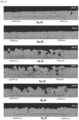
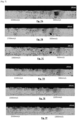
- the objective of these tests was to analyze the morphology of the surface part of each sample after the melting and solidification phases.
- the surface part having undergone these phase changes is designated by the term "molten zone". It is considered representative of the morphology of the layers formed by additive manufacturing.
- the tests made it possible to characterize the surface condition of the samples, in particular porosity and roughness. Each sample was cut according to thickness, the latter having been characterized using an optical microscope. The results of the characterizations, for different compositions, are represented on the Figures 5A to 5F , 6A to 6F , 7A to 7F , 8A to 8F , 9A to 9F , 10A to 10F .
- Each figure corresponds to a cut made at constant power, by varying the scanning speed between a minimum speed, indicated on the left of the figure, and a maximum speed, indicated on the right of the figure.
- Each figure thus shows the profiles of the surface exposed to the laser beam for different speeds, at the same power.
- FIGS. 5A, 5B, 5C, 5D, 5E and 5F show the sections obtained with samples whose composition corresponds to the reference composition described in table 1, respectively for powers 250 W, 300 W, 350 W, 400 W, 450 W, 500 W.
- FIGS. 6A, 6B, 6C, 6D, 6E and 6F show the sections obtained with samples whose composition corresponds to composition no. 1 described in table 1 (4% Mg; 1.5% Zr - 2% Cu), respectively for powers 250 W, 300 W, 350 W , 400W, 450W, 500W.
- FIGS. 7A, 7B, 7C, 7D, 7E and 7F show the sections obtained with samples whose composition corresponds to composition no. 5 described in table 1 (4% Mg; 1.5% Zr - 2% Ni), respectively for powers 250 W, 300 W, 350 W , 400W, 450W, 500W.
- FIGS. 8A, 8B, 8C, 8D, 8E and 8F show the sections obtained with samples whose composition corresponds to composition no. 3 described in table 1 (4% Mg; 1.5% Zr - 2% Fe), respectively for powers 250 W, 300 W, 350 W , 400W, 450W, 500W.
- FIGS. 9A, 9B, 9C, 9D, 9E and 9F show the sections obtained with samples whose composition corresponds to composition no. 6 described in table 1 (4% Mg; 1.5% Zr - 2% Mn), respectively for powers 250 W, 300 W, 350 W , 400W, 450W, 500W.
- FIGS. 10A, 10B, 10C, 10D, 10E and 10F show the sections obtained with samples whose composition corresponds to composition no. 9 described in table 1 (4% Mg; 1.5% Zr - 2% La), respectively for powers 250 W, 300 W, 350 W , 400W, 450W, 500W.
- compositions which were the subject of the tests reported on the figures 6 to 10 correspond to those giving rise to the most favorable hardness values during the first series of tests. It is observed that these compositions make it possible to obtain a smoother and less porous surface state than the reference composition. They are therefore better suited to being used in an additive manufacturing process. In addition, these compositions make it possible to obtain satisfactory surface conditions at high speed and high power. They are particularly suitable for implementing an additive manufacturing process with high build rates.
- Test parts were produced by SLM, using an alloy 11, whose mass composition measured by ICP included: Al; Zr 1.64%; Fe 2.12%; Mg 2.56%; impurities: ⁇ 0.05% each with an accumulation of impurities ⁇ 0.15%.
- This machine allows heating of the plate up to a temperature of 200°C.
- the tests were carried out at a heating temperature of 200°C but additional tests showed the good processability of the alloys according to the present invention at lower heating temperatures, for example 25°C, 50°C, 100°C. or 150°C.
- the laser power was 370 W.
- the scanning speed was 1250 mm/s.
- the layer thickness was 60 ⁇ m.
- the powder used had a particle size essentially ranging from 3 ⁇ m to 100 ⁇ m, with a median of 38 ⁇ m, a 10% fractile of 14 ⁇ m and a 90% fractile of 78 ⁇ m.
- test pieces were made in the form of solid vertical cylinders (Z direction) relative to the construction plate which forms the base in the plane (XY).
- the cylinders had a diameter of 11 mm and a height of 46 mm. All parts have undergone a 4-hour SLM post-manufacturing stress relief treatment at 300°C.
- Table 4 summarizes the tensile properties (yield strength, tensile strength and elongation at break) as a function of the post-manufacturing heat treatment conditions (duration, temperature). [Table 4] Duration (h) Temperature (°C) Rp0.2 (MPa) Rm (MPa) HAS (%) 0 - 303 369 15.6 1 400 455 457 6.1 4 400 474 475 5.2
- a fourth test similar to test 3 was carried out using alloy 4 whose mass composition measured by ICP included Al; Zr 1.3%; Mn 4.47%; Mg 2.53%; impurities: ⁇ 0.05% each with an accumulation of impurities ⁇ 0.15%.
- the powder used had a particle size essentially ranging from 3 ⁇ m to 100 ⁇ m, with a median of 40 ⁇ m, a 10% fractile of 14 ⁇ m and a 90% fractile of 84 ⁇ m.
- Table 5 summarizes the tensile properties (yield strength, tensile strength and elongation at break) as a function of the post-manufacturing heat treatment conditions (duration, temperature). [Table 5] Duration (h) Temperature (°C) Rp0.2 (MPa) Rm (MPa) HAS (%) 0 - 372 445 6.9 1 400 424 488 3.8 4 400 435.5 500 3.75
- a fifth test similar to tests 3 and 4 was carried out using alloy 5 whose mass composition measured by ICP included AI; Zr 1.13%; Mn 4.45%; Mg 1.09%; impurities: ⁇ 0.05% each with an accumulation of impurities ⁇ 0.15%.
- the powder used had a particle size essentially ranging from 3 ⁇ m to 100 ⁇ m, with a median of 25 ⁇ m, a 10% fractile of 9.6 ⁇ m and a 90% fractile of 52 ⁇ m.
- compositions previously described can be used in other types of tests.
- FIG. 11 represents a WAAM type additive manufacturing device, mentioned in connection with the prior art.
- An energy source 31 in this case a torch, forms an electric arc 32.
- the torch 31 is held by a welding robot 33.
- the part to be manufactured is placed on a support 10.
- the manufactured part is a wall extending along a transverse axis Z perpendicular to a longitudinal plane XY defined by the support 10.
- a filler wire 35 melts to form a weld bead.
- the welding robot is controlled by a digital model M.
- the filler wire is moved so as to form different layers 20 1 ...20 n , stacked on top of each other, forming the wall 20, each layer corresponding to a weld bead.
- Each layer 20 1 ...20 n extends in the longitudinal plane XY, according to a pattern defined by the digital model M.
- the diameter of the filler wire is preferably less than 3 mm. It can be from 0.5 mm to 3 mm and is preferably from 0.5 mm to 2 mm, or even from 1 mm to 2 mm. It is for example 1.2 mm.
Landscapes
- Chemical & Material Sciences (AREA)
- Engineering & Computer Science (AREA)
- Materials Engineering (AREA)
- Manufacturing & Machinery (AREA)
- Mechanical Engineering (AREA)
- Physics & Mathematics (AREA)
- Metallurgy (AREA)
- Organic Chemistry (AREA)
- Thermal Sciences (AREA)
- Crystallography & Structural Chemistry (AREA)
- Optics & Photonics (AREA)
- Plasma & Fusion (AREA)
- Powder Metallurgy (AREA)
- Laser Beam Processing (AREA)
- Other Surface Treatments For Metallic Materials (AREA)
- Laminated Bodies (AREA)
- Pressure Welding/Diffusion-Bonding (AREA)
- Manufacture Of Metal Powder And Suspensions Thereof (AREA)
- Piezo-Electric Or Mechanical Vibrators, Or Delay Or Filter Circuits (AREA)
- Materials For Medical Uses (AREA)
- Control Of Motors That Do Not Use Commutators (AREA)
Applications Claiming Priority (3)
| Application Number | Priority Date | Filing Date | Title |
|---|---|---|---|
| FR1900598A FR3092119B1 (fr) | 2019-01-24 | 2019-01-24 | Procédé de fabrication d'une pièce en alliage d'aluminium, l'alliage comportant au moins du zirconium et du magnésium |
| PCT/FR2020/050107 WO2020152427A1 (fr) | 2019-01-24 | 2020-01-24 | Procede de fabrication d'une piece en alliage d'aluminium, l'alliage comportant au moins du zirconium et du magnesium |
| EP20707710.8A EP3914748B1 (de) | 2019-01-24 | 2020-01-24 | Verfahren zur herstellung eines bauteils aus einer aluminiumlegierung, wobei die legierung mindestens zirkonium und magnesium enthält |
Related Parent Applications (1)
| Application Number | Title | Priority Date | Filing Date |
|---|---|---|---|
| EP20707710.8A Division EP3914748B1 (de) | 2019-01-24 | 2020-01-24 | Verfahren zur herstellung eines bauteils aus einer aluminiumlegierung, wobei die legierung mindestens zirkonium und magnesium enthält |
Publications (2)
| Publication Number | Publication Date |
|---|---|
| EP4375392A2 true EP4375392A2 (de) | 2024-05-29 |
| EP4375392A3 EP4375392A3 (de) | 2024-09-11 |
Family
ID=66641141
Family Applications (3)
| Application Number | Title | Priority Date | Filing Date |
|---|---|---|---|
| EP20706787.7A Active EP3914746B1 (de) | 2019-01-24 | 2020-01-24 | Verfahren zur herstellung eines aluminiumlegierungsteils |
| EP24168267.3A Pending EP4375392A3 (de) | 2019-01-24 | 2020-01-24 | Verfahren zur herstellung eines bauteils aus einer aluminiumegierung, wobei die legierung mindestens zirkonium und magensium enthalt |
| EP20707710.8A Active EP3914748B1 (de) | 2019-01-24 | 2020-01-24 | Verfahren zur herstellung eines bauteils aus einer aluminiumlegierung, wobei die legierung mindestens zirkonium und magnesium enthält |
Family Applications Before (1)
| Application Number | Title | Priority Date | Filing Date |
|---|---|---|---|
| EP20706787.7A Active EP3914746B1 (de) | 2019-01-24 | 2020-01-24 | Verfahren zur herstellung eines aluminiumlegierungsteils |
Family Applications After (1)
| Application Number | Title | Priority Date | Filing Date |
|---|---|---|---|
| EP20707710.8A Active EP3914748B1 (de) | 2019-01-24 | 2020-01-24 | Verfahren zur herstellung eines bauteils aus einer aluminiumlegierung, wobei die legierung mindestens zirkonium und magnesium enthält |
Country Status (12)
| Country | Link |
|---|---|
| US (2) | US20220119926A1 (de) |
| EP (3) | EP3914746B1 (de) |
| JP (2) | JP7530368B2 (de) |
| KR (2) | KR102855094B1 (de) |
| CN (2) | CN113330132A (de) |
| CA (2) | CA3125747A1 (de) |
| DE (2) | DE20707710T1 (de) |
| ES (2) | ES2946133T3 (de) |
| FI (1) | FI3914748T5 (de) |
| FR (2) | FR3092119B1 (de) |
| PL (1) | PL3914746T3 (de) |
| WO (1) | WO2020152427A1 (de) |
Families Citing this family (24)
| Publication number | Priority date | Publication date | Assignee | Title |
|---|---|---|---|---|
| FR3092777A1 (fr) * | 2019-02-15 | 2020-08-21 | C-Tec Constellium Technology Center | Procédé de fabrication d'une pièce en alliage d'aluminium |
| CN111872386B (zh) * | 2020-06-30 | 2021-12-31 | 同济大学 | 一种高强度铝镁合金的3d打印工艺方法 |
| US12415229B2 (en) | 2020-07-29 | 2025-09-16 | Blue Origin Manufacturing, LLC | Friction stir welding systems and methods |
| US20220170138A1 (en) * | 2020-12-02 | 2022-06-02 | GM Global Technology Operations LLC | Aluminum alloy for casting and additive manufacturing of engine components for high temperature applications |
| US20220195561A1 (en) * | 2020-12-21 | 2022-06-23 | Divergent Technologies, Inc. | 3-d printable alloys |
| CN112831694B (zh) * | 2020-12-30 | 2022-12-20 | 上海交通大学 | 一种适用于增材制造的稀土铝合金粉末及其制备方法 |
| FR3123235A1 (fr) * | 2021-05-28 | 2022-12-02 | C-Tec Constellium Technology Center | Procédé de fabrication d'une pièce en alliage d'aluminium mettant en œuvre une technique de fabrication additive avec préchauffage. |
| CN113512671B (zh) * | 2021-06-15 | 2022-06-21 | 中车工业研究院有限公司 | 一种3D打印用高强韧AlCrSc合金粉末及其制备方法与应用 |
| CN113430432B (zh) * | 2021-06-29 | 2022-03-01 | 哈尔滨工业大学 | 一种高Zn轻质高强铝合金的制备方法 |
| CN113444922B (zh) * | 2021-06-30 | 2022-04-01 | 赣州虔博新材料科技有限公司 | 稀土铝合金导体材料及其制备方法 |
| CN114381635B (zh) * | 2022-01-18 | 2022-11-11 | 广西大学 | 电池托盘用含稀土晶粒细化剂的铝合金及其制备方法 |
| CN114959379B (zh) * | 2022-03-31 | 2023-04-25 | 华南理工大学 | 一种适用于激光选区熔化的耐热高强铝合金及其制备方法 |
| FR3136390B1 (fr) * | 2022-06-10 | 2025-03-14 | C Tec Constellium Tech Center | Procédé de fabrication d'une pièce en alliage d'aluminium |
| CN115958328A (zh) * | 2022-12-29 | 2023-04-14 | 中铝广西有色稀土开发有限公司 | 一种稀土元素增强的铝合金焊丝及其制备方法 |
| US20240218486A1 (en) * | 2023-01-03 | 2024-07-04 | Eos Of North America, Inc. | Aluminum alloy for additive manufacturing |
| US12172229B2 (en) | 2023-03-30 | 2024-12-24 | Blue Origin, Llc | Friction stir additive manufacturing devices and methods for forming in-situ rivets |
| CN116536551B (zh) * | 2023-05-06 | 2023-11-21 | 河北科技大学 | 一种高强耐热高导电枢材料及其制备方法 |
| US12303994B2 (en) * | 2023-08-03 | 2025-05-20 | Blue Origin Manufacturing, LLC | Friction stir additive manufacturing formed parts and structures with integrated passages |
| US12383975B2 (en) | 2023-08-03 | 2025-08-12 | Blue Origin Manufacturing, LLC | Friction stir additive manufacturing formed parts and structures with integrated passages |
| CN117187638B (zh) * | 2023-09-12 | 2025-08-19 | 上海交通大学 | 一种增材制造用铝镁硅合金及其制备方法 |
| US12589446B2 (en) | 2023-12-12 | 2026-03-31 | Blue Origin Manufacturing, LLC | Wire-feed friction stir additive manufacturing systems, devices, and methods |
| FR3157440A1 (fr) | 2023-12-21 | 2025-06-27 | C-Tec Constellium Technology Center | Procede de fabrication d'une piece en alliage d'aluminium |
| CN118581342A (zh) * | 2024-05-20 | 2024-09-03 | 山东创新精密科技有限公司 | 一种导热与力学性能相协调的铝合金的制备工艺 |
| CN119973313B (zh) * | 2025-01-22 | 2025-10-28 | 首都航天机械有限公司 | 免淬火热处理提升电弧增材铝合金力学性能的方法 |
Citations (4)
| Publication number | Priority date | Publication date | Assignee | Title |
|---|---|---|---|---|
| US1609617A (en) | 1926-06-15 | 1926-12-07 | William O Frohring | Method of increasing the coagulating point of milk |
| WO2015006447A1 (en) | 2013-07-10 | 2015-01-15 | Alcoa Inc. | Methods for producing forged products and other worked products |
| WO2018009359A1 (en) | 2016-07-05 | 2018-01-11 | NanoAL LLC | Ribbons and powders from high strength corrosion resistant aluminum alloys |
| WO2018185259A1 (de) | 2017-04-05 | 2018-10-11 | Amag Casting Gmbh | Ausgangswerkstoff, dessen verwendung und additives fertigungsverfahren mit diesem ausgangswerkstoff |
Family Cites Families (28)
| Publication number | Priority date | Publication date | Assignee | Title |
|---|---|---|---|---|
| SU439535A1 (ru) | 1972-07-04 | 1974-08-15 | Предприятие П/Я Р-6209 | Сплав на основе алюмини |
| JPS597493A (ja) | 1982-07-07 | 1984-01-14 | Furukawa Alum Co Ltd | アルミニウム合金溶加材 |
| JP2711296B2 (ja) * | 1988-03-24 | 1998-02-10 | 東洋アルミニウム株式会社 | 耐熱性アルミニウム合金 |
| JP2693175B2 (ja) | 1988-05-18 | 1997-12-24 | 昭和アルミニウム株式会社 | 耐熱性に優れたアルミニウム合金 |
| JPH0417637A (ja) * | 1990-05-09 | 1992-01-22 | Furukawa Alum Co Ltd | アルミニウム合金制振材料およびその製造方法 |
| JPH04187701A (ja) * | 1990-11-20 | 1992-07-06 | Honda Motor Co Ltd | 粉末冶金用アルミニウム合金粉末、圧粉体および焼結体 |
| JP2000144489A (ja) * | 1998-10-30 | 2000-05-26 | Sumitomo Electric Ind Ltd | 装飾用アルミニウム合金部材およびその製造方法 |
| JP2008261004A (ja) * | 2007-04-11 | 2008-10-30 | Sumitomo Denko Shoketsu Gokin Kk | アルミニウム合金 |
| JP5772731B2 (ja) | 2012-06-08 | 2015-09-02 | 株式会社豊田中央研究所 | アルミニウム合金粉末成形方法およびアルミニウム合金部材 |
| US20170016096A1 (en) | 2015-07-16 | 2017-01-19 | Hamilton Sundstrand Corporation | Method of manufacturing aluminum alloy articles |
| WO2017041006A1 (en) | 2015-09-03 | 2017-03-09 | Questek Innovations Llc | Aluminum alloys |
| US20180318922A1 (en) * | 2015-11-06 | 2018-11-08 | Innomaq 21, S.L. | Method for the economic manufacturing of metallic parts |
| WO2017096050A1 (en) | 2015-12-04 | 2017-06-08 | Raytheon Company | Electron beam additive manufacturing |
| RU2659546C1 (ru) | 2016-07-01 | 2018-07-02 | Общество с ограниченной ответственностью "Объединенная Компания РУСАЛ Инженерно-технологический центр" | Термостойкий сплав на основе алюминия |
| US11603583B2 (en) * | 2016-07-05 | 2023-03-14 | NanoAL LLC | Ribbons and powders from high strength corrosion resistant aluminum alloys |
| US10697046B2 (en) | 2016-07-07 | 2020-06-30 | NanoAL LLC | High-performance 5000-series aluminum alloys and methods for making and using them |
| JP2020503433A (ja) * | 2016-12-21 | 2020-01-30 | アーコニック インコーポレイテッドArconic Inc. | 微細共晶型組織を有するアルミニウム合金製品、およびその製造方法 |
| US11117193B2 (en) * | 2017-02-01 | 2021-09-14 | Hrl Laboratories, Llc | Additive manufacturing with nanofunctionalized precursors |
| US12421576B2 (en) * | 2017-02-01 | 2025-09-23 | Hrl Laboratories, Llc | Aluminum-chromium-zirconium alloys |
| US11578389B2 (en) * | 2017-02-01 | 2023-02-14 | Hrl Laboratories, Llc | Aluminum alloy feedstocks for additive manufacturing |
| KR102570707B1 (ko) * | 2017-02-23 | 2023-08-24 | 후루카와 덴키 고교 가부시키가이샤 | 알루미늄 합금재 그리고 이것을 사용한 체결 부품, 구조용 부품, 스프링용 부품, 도전 부재 및 전지용 부재 |
| FR3065178B1 (fr) * | 2017-04-14 | 2022-04-29 | C Tec Constellium Tech Center | Procede de fabrication d'une piece en alliage d'aluminium |
| JP6393008B1 (ja) * | 2017-04-27 | 2018-09-19 | 株式会社コイワイ | 高強度アルミニウム合金積層成形体及びその製造方法 |
| FR3066129B1 (fr) * | 2017-05-12 | 2019-06-28 | C-Tec Constellium Technology Center | Procede de fabrication d'une piece en alliage d'aluminium |
| CN107876948B (zh) * | 2017-11-20 | 2020-02-14 | 华中科技大学 | 一种金属间化合物零件的增材制造方法 |
| FR3075827B1 (fr) * | 2017-12-26 | 2022-04-01 | Thales Sa | Poudre d'alliage d'aluminium pour fabrication additive, et procede de fabrication d'une piece par fabrication a partir de cette poudre |
| CN108330344B (zh) * | 2018-03-20 | 2020-08-04 | 中南大学 | 一种3D打印7xxx铝合金及其制备方法 |
| WO2020117090A1 (ru) | 2018-12-07 | 2020-06-11 | Акционерное Общество "Объединенная Компания Русал Уральский Алюминий" | Поршковый алюминиевый материал |
-
2019
- 2019-01-24 FR FR1900598A patent/FR3092119B1/fr active Active
- 2019-07-30 FR FR1908684A patent/FR3092120B1/fr active Active
-
2020
- 2020-01-24 JP JP2021543268A patent/JP7530368B2/ja active Active
- 2020-01-24 WO PCT/FR2020/050107 patent/WO2020152427A1/fr not_active Ceased
- 2020-01-24 ES ES20706787T patent/ES2946133T3/es active Active
- 2020-01-24 EP EP20706787.7A patent/EP3914746B1/de active Active
- 2020-01-24 EP EP24168267.3A patent/EP4375392A3/de active Pending
- 2020-01-24 US US17/424,671 patent/US20220119926A1/en active Pending
- 2020-01-24 JP JP2021543270A patent/JP7530369B2/ja active Active
- 2020-01-24 CA CA3125747A patent/CA3125747A1/fr active Pending
- 2020-01-24 CA CA3125851A patent/CA3125851A1/en active Pending
- 2020-01-24 ES ES20707710T patent/ES2992752T3/es active Active
- 2020-01-24 PL PL20706787.7T patent/PL3914746T3/pl unknown
- 2020-01-24 CN CN202080010547.3A patent/CN113330132A/zh active Pending
- 2020-01-24 FI FIEP20707710.8T patent/FI3914748T5/en active
- 2020-01-24 EP EP20707710.8A patent/EP3914748B1/de active Active
- 2020-01-24 DE DE20707710.8T patent/DE20707710T1/de active Pending
- 2020-01-24 KR KR1020217026604A patent/KR102855094B1/ko active Active
- 2020-01-24 US US17/424,285 patent/US12377463B2/en active Active
- 2020-01-24 DE DE20706787.7T patent/DE20706787T1/de active Pending
- 2020-01-24 KR KR1020217026606A patent/KR102855095B1/ko active Active
- 2020-01-24 CN CN202080010843.3A patent/CN113348262A/zh active Pending
Patent Citations (4)
| Publication number | Priority date | Publication date | Assignee | Title |
|---|---|---|---|---|
| US1609617A (en) | 1926-06-15 | 1926-12-07 | William O Frohring | Method of increasing the coagulating point of milk |
| WO2015006447A1 (en) | 2013-07-10 | 2015-01-15 | Alcoa Inc. | Methods for producing forged products and other worked products |
| WO2018009359A1 (en) | 2016-07-05 | 2018-01-11 | NanoAL LLC | Ribbons and powders from high strength corrosion resistant aluminum alloys |
| WO2018185259A1 (de) | 2017-04-05 | 2018-10-11 | Amag Casting Gmbh | Ausgangswerkstoff, dessen verwendung und additives fertigungsverfahren mit diesem ausgangswerkstoff |
Also Published As
| Publication number | Publication date |
|---|---|
| PL3914746T3 (pl) | 2023-06-12 |
| US20220088681A1 (en) | 2022-03-24 |
| KR20210118132A (ko) | 2021-09-29 |
| KR20210118131A (ko) | 2021-09-29 |
| CN113348262A (zh) | 2021-09-03 |
| JP2022518791A (ja) | 2022-03-16 |
| CN113330132A (zh) | 2021-08-31 |
| JP2022527425A (ja) | 2022-06-02 |
| FR3092119A1 (fr) | 2020-07-31 |
| KR102855094B1 (ko) | 2025-09-04 |
| US12377463B2 (en) | 2025-08-05 |
| FI3914748T5 (en) | 2024-08-05 |
| FR3092119B1 (fr) | 2020-12-25 |
| US20220119926A1 (en) | 2022-04-21 |
| DE20707710T1 (de) | 2022-03-17 |
| EP3914748B1 (de) | 2024-05-08 |
| EP3914746B1 (de) | 2023-03-08 |
| JP7530369B2 (ja) | 2024-08-07 |
| ES2992752T3 (en) | 2024-12-17 |
| DE20706787T1 (de) | 2022-03-24 |
| CA3125851A1 (en) | 2020-05-14 |
| EP4375392A3 (de) | 2024-09-11 |
| KR102855095B1 (ko) | 2025-09-03 |
| FI3914748T3 (en) | 2024-07-10 |
| FR3092120B1 (fr) | 2021-08-13 |
| ES2946133T3 (es) | 2023-07-13 |
| FR3092120A1 (fr) | 2020-07-31 |
| CA3125747A1 (fr) | 2020-07-30 |
| JP7530368B2 (ja) | 2024-08-07 |
| EP3914746A2 (de) | 2021-12-01 |
| WO2020152427A1 (fr) | 2020-07-30 |
| EP3914748A1 (de) | 2021-12-01 |
Similar Documents
| Publication | Publication Date | Title |
|---|---|---|
| EP3914748B1 (de) | Verfahren zur herstellung eines bauteils aus einer aluminiumlegierung, wobei die legierung mindestens zirkonium und magnesium enthält | |
| EP3860788B1 (de) | Verfahren zur herstellung eines aluminiumlegierungsteils und ein aluminiumlegierungspulver | |
| EP3860787B1 (de) | Verfahren zur herstellung eines aluminiumlegierungsteils | |
| EP4061563B1 (de) | Verfahren zur herstellung eines aluminiumlegierungsteils | |
| EP3821047A1 (de) | Verfahren zur herstellung von aluminiumlegierungsteilen | |
| EP3924124B1 (de) | Verfahren zur herstellung eines aluminiumlegierungsteils | |
| EP4149703B1 (de) | Verfahren zur herstellung eines aluminiumlegierungsteils | |
| WO2020165543A1 (fr) | Procede de fabrication d'une pièce en alliage d'aluminium | |
| WO2021156583A2 (fr) | Procédé de fabrication d'une pièce en alliage d'aluminium | |
| EP3821049A1 (de) | Verfahren zur herstellung eines aluminiumlegierungsteils | |
| EP3810817A1 (de) | Verfahren zur herstellung eines aluminiumlegierungsteils | |
| FR3139018A1 (fr) | Procédé de fabrication d'une pièce en alliage d'aluminium | |
| FR3136390A1 (fr) | Procédé de fabrication d'une pièce en alliage d'aluminium | |
| WO2020002813A1 (fr) | Procede de fabrication d'une piece en alliage d'aluminium | |
| WO2020095009A2 (fr) | Procédé de fabrication d'une pièce en alliage d'aluminium | |
| WO2020070453A1 (fr) | Procede de fabrication d'une piece en alliage d'aluminium | |
| WO2025133519A1 (fr) | Procede de fabrication d'une piece en alliage d'aluminium | |
| FR3157238A1 (fr) | Procédé de fabrication d'une pièce en alliage d'aluminium | |
| WO2025133522A1 (fr) | Procede de fabrication d'une piece en alliage d'aluminium |
Legal Events
| Date | Code | Title | Description |
|---|---|---|---|
| PUAI | Public reference made under article 153(3) epc to a published international application that has entered the european phase |
Free format text: ORIGINAL CODE: 0009012 |
|
| STAA | Information on the status of an ep patent application or granted ep patent |
Free format text: STATUS: THE APPLICATION HAS BEEN PUBLISHED |
|
| AC | Divisional application: reference to earlier application |
Ref document number: 3914748 Country of ref document: EP Kind code of ref document: P |
|
| AK | Designated contracting states |
Kind code of ref document: A2 Designated state(s): AL AT BE BG CH CY CZ DE DK EE ES FI FR GB GR HR HU IE IS IT LI LT LU LV MC MK MT NL NO PL PT RO RS SE SI SK SM TR |
|
| REG | Reference to a national code |
Ref country code: DE Ref legal event code: R079 Free format text: PREVIOUS MAIN CLASS: C22F0001047000 Ipc: C22C0021060000 |
|
| PUAL | Search report despatched |
Free format text: ORIGINAL CODE: 0009013 |
|
| AK | Designated contracting states |
Kind code of ref document: A3 Designated state(s): AL AT BE BG CH CY CZ DE DK EE ES FI FR GB GR HR HU IE IS IT LI LT LU LV MC MK MT NL NO PL PT RO RS SE SI SK SM TR |
|
| RIC1 | Information provided on ipc code assigned before grant |
Ipc: C22F 1/047 20060101ALI20240802BHEP Ipc: C22F 1/04 20060101ALI20240802BHEP Ipc: B33Y 80/00 20150101ALI20240802BHEP Ipc: B33Y 70/00 20200101ALI20240802BHEP Ipc: B23K 26/342 20140101ALI20240802BHEP Ipc: B22F 3/105 20060101ALI20240802BHEP Ipc: C22C 21/00 20060101ALI20240802BHEP Ipc: C22C 21/06 20060101AFI20240802BHEP |
|
| STAA | Information on the status of an ep patent application or granted ep patent |
Free format text: STATUS: REQUEST FOR EXAMINATION WAS MADE |
|
| 17P | Request for examination filed |
Effective date: 20250310 |