EP4470505A2 - Valve prothétique télescopique et système de pose - Google Patents
Valve prothétique télescopique et système de pose Download PDFInfo
- Publication number
- EP4470505A2 EP4470505A2 EP24187369.4A EP24187369A EP4470505A2 EP 4470505 A2 EP4470505 A2 EP 4470505A2 EP 24187369 A EP24187369 A EP 24187369A EP 4470505 A2 EP4470505 A2 EP 4470505A2
- Authority
- EP
- European Patent Office
- Prior art keywords
- frame subcomponent
- valve
- anchor frame
- subcomponent
- examples
- Prior art date
- Legal status (The legal status is an assumption and is not a legal conclusion. Google has not performed a legal analysis and makes no representation as to the accuracy of the status listed.)
- Pending
Links
Images











Classifications
-
- A—HUMAN NECESSITIES
- A61—MEDICAL OR VETERINARY SCIENCE; HYGIENE
- A61F—FILTERS IMPLANTABLE INTO BLOOD VESSELS; PROSTHESES; DEVICES PROVIDING PATENCY TO, OR PREVENTING COLLAPSING OF, TUBULAR STRUCTURES OF THE BODY, e.g. STENTS; ORTHOPAEDIC, NURSING OR CONTRACEPTIVE DEVICES; FOMENTATION; TREATMENT OR PROTECTION OF EYES OR EARS; BANDAGES, DRESSINGS OR ABSORBENT PADS; FIRST-AID KITS
- A61F2/00—Filters implantable into blood vessels; Prostheses, i.e. artificial substitutes or replacements for parts of the body; Appliances for connecting them with the body; Devices providing patency to, or preventing collapsing of, tubular structures of the body, e.g. stents
- A61F2/02—Prostheses implantable into the body
- A61F2/24—Heart valves ; Vascular valves, e.g. venous valves; Heart implants, e.g. passive devices for improving the function of the native valve or the heart muscle; Transmyocardial revascularisation [TMR] devices; Valves implantable in the body
- A61F2/2412—Heart valves ; Vascular valves, e.g. venous valves; Heart implants, e.g. passive devices for improving the function of the native valve or the heart muscle; Transmyocardial revascularisation [TMR] devices; Valves implantable in the body with soft flexible valve members, e.g. tissue valves shaped like natural valves
- A61F2/2418—Scaffolds therefor, e.g. support stents
-
- A—HUMAN NECESSITIES
- A61—MEDICAL OR VETERINARY SCIENCE; HYGIENE
- A61F—FILTERS IMPLANTABLE INTO BLOOD VESSELS; PROSTHESES; DEVICES PROVIDING PATENCY TO, OR PREVENTING COLLAPSING OF, TUBULAR STRUCTURES OF THE BODY, e.g. STENTS; ORTHOPAEDIC, NURSING OR CONTRACEPTIVE DEVICES; FOMENTATION; TREATMENT OR PROTECTION OF EYES OR EARS; BANDAGES, DRESSINGS OR ABSORBENT PADS; FIRST-AID KITS
- A61F2/00—Filters implantable into blood vessels; Prostheses, i.e. artificial substitutes or replacements for parts of the body; Appliances for connecting them with the body; Devices providing patency to, or preventing collapsing of, tubular structures of the body, e.g. stents
- A61F2/02—Prostheses implantable into the body
- A61F2/24—Heart valves ; Vascular valves, e.g. venous valves; Heart implants, e.g. passive devices for improving the function of the native valve or the heart muscle; Transmyocardial revascularisation [TMR] devices; Valves implantable in the body
- A61F2/2427—Devices for manipulating or deploying heart valves during implantation
- A61F2/2436—Deployment by retracting a sheath
-
- A—HUMAN NECESSITIES
- A61—MEDICAL OR VETERINARY SCIENCE; HYGIENE
- A61F—FILTERS IMPLANTABLE INTO BLOOD VESSELS; PROSTHESES; DEVICES PROVIDING PATENCY TO, OR PREVENTING COLLAPSING OF, TUBULAR STRUCTURES OF THE BODY, e.g. STENTS; ORTHOPAEDIC, NURSING OR CONTRACEPTIVE DEVICES; FOMENTATION; TREATMENT OR PROTECTION OF EYES OR EARS; BANDAGES, DRESSINGS OR ABSORBENT PADS; FIRST-AID KITS
- A61F2/00—Filters implantable into blood vessels; Prostheses, i.e. artificial substitutes or replacements for parts of the body; Appliances for connecting them with the body; Devices providing patency to, or preventing collapsing of, tubular structures of the body, e.g. stents
- A61F2/02—Prostheses implantable into the body
- A61F2/24—Heart valves ; Vascular valves, e.g. venous valves; Heart implants, e.g. passive devices for improving the function of the native valve or the heart muscle; Transmyocardial revascularisation [TMR] devices; Valves implantable in the body
- A61F2/2442—Annuloplasty rings or inserts for correcting the valve shape; Implants for improving the function of a native heart valve
- A61F2/246—Devices for obstructing a leak through a native valve in a closed condition
-
- A—HUMAN NECESSITIES
- A61—MEDICAL OR VETERINARY SCIENCE; HYGIENE
- A61F—FILTERS IMPLANTABLE INTO BLOOD VESSELS; PROSTHESES; DEVICES PROVIDING PATENCY TO, OR PREVENTING COLLAPSING OF, TUBULAR STRUCTURES OF THE BODY, e.g. STENTS; ORTHOPAEDIC, NURSING OR CONTRACEPTIVE DEVICES; FOMENTATION; TREATMENT OR PROTECTION OF EYES OR EARS; BANDAGES, DRESSINGS OR ABSORBENT PADS; FIRST-AID KITS
- A61F2/00—Filters implantable into blood vessels; Prostheses, i.e. artificial substitutes or replacements for parts of the body; Appliances for connecting them with the body; Devices providing patency to, or preventing collapsing of, tubular structures of the body, e.g. stents
- A61F2/02—Prostheses implantable into the body
- A61F2/24—Heart valves ; Vascular valves, e.g. venous valves; Heart implants, e.g. passive devices for improving the function of the native valve or the heart muscle; Transmyocardial revascularisation [TMR] devices; Valves implantable in the body
- A61F2/2427—Devices for manipulating or deploying heart valves during implantation
- A61F2/243—Deployment by mechanical expansion
- A61F2/2433—Deployment by mechanical expansion using balloon catheter
-
- A—HUMAN NECESSITIES
- A61—MEDICAL OR VETERINARY SCIENCE; HYGIENE
- A61F—FILTERS IMPLANTABLE INTO BLOOD VESSELS; PROSTHESES; DEVICES PROVIDING PATENCY TO, OR PREVENTING COLLAPSING OF, TUBULAR STRUCTURES OF THE BODY, e.g. STENTS; ORTHOPAEDIC, NURSING OR CONTRACEPTIVE DEVICES; FOMENTATION; TREATMENT OR PROTECTION OF EYES OR EARS; BANDAGES, DRESSINGS OR ABSORBENT PADS; FIRST-AID KITS
- A61F2/00—Filters implantable into blood vessels; Prostheses, i.e. artificial substitutes or replacements for parts of the body; Appliances for connecting them with the body; Devices providing patency to, or preventing collapsing of, tubular structures of the body, e.g. stents
- A61F2/02—Prostheses implantable into the body
- A61F2/24—Heart valves ; Vascular valves, e.g. venous valves; Heart implants, e.g. passive devices for improving the function of the native valve or the heart muscle; Transmyocardial revascularisation [TMR] devices; Valves implantable in the body
- A61F2/2427—Devices for manipulating or deploying heart valves during implantation
- A61F2/2439—Expansion controlled by filaments
-
- A—HUMAN NECESSITIES
- A61—MEDICAL OR VETERINARY SCIENCE; HYGIENE
- A61F—FILTERS IMPLANTABLE INTO BLOOD VESSELS; PROSTHESES; DEVICES PROVIDING PATENCY TO, OR PREVENTING COLLAPSING OF, TUBULAR STRUCTURES OF THE BODY, e.g. STENTS; ORTHOPAEDIC, NURSING OR CONTRACEPTIVE DEVICES; FOMENTATION; TREATMENT OR PROTECTION OF EYES OR EARS; BANDAGES, DRESSINGS OR ABSORBENT PADS; FIRST-AID KITS
- A61F2/00—Filters implantable into blood vessels; Prostheses, i.e. artificial substitutes or replacements for parts of the body; Appliances for connecting them with the body; Devices providing patency to, or preventing collapsing of, tubular structures of the body, e.g. stents
- A61F2/02—Prostheses implantable into the body
- A61F2/24—Heart valves ; Vascular valves, e.g. venous valves; Heart implants, e.g. passive devices for improving the function of the native valve or the heart muscle; Transmyocardial revascularisation [TMR] devices; Valves implantable in the body
- A61F2/2442—Annuloplasty rings or inserts for correcting the valve shape; Implants for improving the function of a native heart valve
- A61F2/2454—Means for preventing inversion of the valve leaflets, e.g. chordae tendineae prostheses
-
- A—HUMAN NECESSITIES
- A61—MEDICAL OR VETERINARY SCIENCE; HYGIENE
- A61F—FILTERS IMPLANTABLE INTO BLOOD VESSELS; PROSTHESES; DEVICES PROVIDING PATENCY TO, OR PREVENTING COLLAPSING OF, TUBULAR STRUCTURES OF THE BODY, e.g. STENTS; ORTHOPAEDIC, NURSING OR CONTRACEPTIVE DEVICES; FOMENTATION; TREATMENT OR PROTECTION OF EYES OR EARS; BANDAGES, DRESSINGS OR ABSORBENT PADS; FIRST-AID KITS
- A61F2/00—Filters implantable into blood vessels; Prostheses, i.e. artificial substitutes or replacements for parts of the body; Appliances for connecting them with the body; Devices providing patency to, or preventing collapsing of, tubular structures of the body, e.g. stents
- A61F2/82—Devices providing patency to, or preventing collapsing of, tubular structures of the body, e.g. stents
- A61F2002/825—Devices providing patency to, or preventing collapsing of, tubular structures of the body, e.g. stents having longitudinal struts
-
- A—HUMAN NECESSITIES
- A61—MEDICAL OR VETERINARY SCIENCE; HYGIENE
- A61F—FILTERS IMPLANTABLE INTO BLOOD VESSELS; PROSTHESES; DEVICES PROVIDING PATENCY TO, OR PREVENTING COLLAPSING OF, TUBULAR STRUCTURES OF THE BODY, e.g. STENTS; ORTHOPAEDIC, NURSING OR CONTRACEPTIVE DEVICES; FOMENTATION; TREATMENT OR PROTECTION OF EYES OR EARS; BANDAGES, DRESSINGS OR ABSORBENT PADS; FIRST-AID KITS
- A61F2210/00—Particular material properties of prostheses classified in groups A61F2/00 - A61F2/26 or A61F2/82 or A61F9/00 or A61F11/00 or subgroups thereof
- A61F2210/0014—Particular material properties of prostheses classified in groups A61F2/00 - A61F2/26 or A61F2/82 or A61F9/00 or A61F11/00 or subgroups thereof using shape memory or superelastic materials, e.g. nitinol
-
- A—HUMAN NECESSITIES
- A61—MEDICAL OR VETERINARY SCIENCE; HYGIENE
- A61F—FILTERS IMPLANTABLE INTO BLOOD VESSELS; PROSTHESES; DEVICES PROVIDING PATENCY TO, OR PREVENTING COLLAPSING OF, TUBULAR STRUCTURES OF THE BODY, e.g. STENTS; ORTHOPAEDIC, NURSING OR CONTRACEPTIVE DEVICES; FOMENTATION; TREATMENT OR PROTECTION OF EYES OR EARS; BANDAGES, DRESSINGS OR ABSORBENT PADS; FIRST-AID KITS
- A61F2220/00—Fixations or connections for prostheses classified in groups A61F2/00 - A61F2/26 or A61F2/82 or A61F9/00 or A61F11/00 or subgroups thereof
- A61F2220/0008—Fixation appliances for connecting prostheses to the body
- A61F2220/0016—Fixation appliances for connecting prostheses to the body with sharp anchoring protrusions, e.g. barbs, pins, spikes
-
- A—HUMAN NECESSITIES
- A61—MEDICAL OR VETERINARY SCIENCE; HYGIENE
- A61F—FILTERS IMPLANTABLE INTO BLOOD VESSELS; PROSTHESES; DEVICES PROVIDING PATENCY TO, OR PREVENTING COLLAPSING OF, TUBULAR STRUCTURES OF THE BODY, e.g. STENTS; ORTHOPAEDIC, NURSING OR CONTRACEPTIVE DEVICES; FOMENTATION; TREATMENT OR PROTECTION OF EYES OR EARS; BANDAGES, DRESSINGS OR ABSORBENT PADS; FIRST-AID KITS
- A61F2220/00—Fixations or connections for prostheses classified in groups A61F2/00 - A61F2/26 or A61F2/82 or A61F9/00 or A61F11/00 or subgroups thereof
- A61F2220/0025—Connections or couplings between prosthetic parts, e.g. between modular parts; Connecting elements
- A61F2220/0075—Connections or couplings between prosthetic parts, e.g. between modular parts; Connecting elements sutured, ligatured or stitched, retained or tied with a rope, string, thread, wire or cable
-
- A—HUMAN NECESSITIES
- A61—MEDICAL OR VETERINARY SCIENCE; HYGIENE
- A61F—FILTERS IMPLANTABLE INTO BLOOD VESSELS; PROSTHESES; DEVICES PROVIDING PATENCY TO, OR PREVENTING COLLAPSING OF, TUBULAR STRUCTURES OF THE BODY, e.g. STENTS; ORTHOPAEDIC, NURSING OR CONTRACEPTIVE DEVICES; FOMENTATION; TREATMENT OR PROTECTION OF EYES OR EARS; BANDAGES, DRESSINGS OR ABSORBENT PADS; FIRST-AID KITS
- A61F2230/00—Geometry of prostheses classified in groups A61F2/00 - A61F2/26 or A61F2/82 or A61F9/00 or A61F11/00 or subgroups thereof
- A61F2230/0002—Two-dimensional shapes, e.g. cross-sections
- A61F2230/0028—Shapes in the form of latin or greek characters
- A61F2230/005—Rosette-shaped, e.g. star-shaped
-
- A—HUMAN NECESSITIES
- A61—MEDICAL OR VETERINARY SCIENCE; HYGIENE
- A61F—FILTERS IMPLANTABLE INTO BLOOD VESSELS; PROSTHESES; DEVICES PROVIDING PATENCY TO, OR PREVENTING COLLAPSING OF, TUBULAR STRUCTURES OF THE BODY, e.g. STENTS; ORTHOPAEDIC, NURSING OR CONTRACEPTIVE DEVICES; FOMENTATION; TREATMENT OR PROTECTION OF EYES OR EARS; BANDAGES, DRESSINGS OR ABSORBENT PADS; FIRST-AID KITS
- A61F2230/00—Geometry of prostheses classified in groups A61F2/00 - A61F2/26 or A61F2/82 or A61F9/00 or A61F11/00 or subgroups thereof
- A61F2230/0002—Two-dimensional shapes, e.g. cross-sections
- A61F2230/0028—Shapes in the form of latin or greek characters
- A61F2230/0052—T-shaped
-
- A—HUMAN NECESSITIES
- A61—MEDICAL OR VETERINARY SCIENCE; HYGIENE
- A61F—FILTERS IMPLANTABLE INTO BLOOD VESSELS; PROSTHESES; DEVICES PROVIDING PATENCY TO, OR PREVENTING COLLAPSING OF, TUBULAR STRUCTURES OF THE BODY, e.g. STENTS; ORTHOPAEDIC, NURSING OR CONTRACEPTIVE DEVICES; FOMENTATION; TREATMENT OR PROTECTION OF EYES OR EARS; BANDAGES, DRESSINGS OR ABSORBENT PADS; FIRST-AID KITS
- A61F2230/00—Geometry of prostheses classified in groups A61F2/00 - A61F2/26 or A61F2/82 or A61F9/00 or A61F11/00 or subgroups thereof
- A61F2230/0002—Two-dimensional shapes, e.g. cross-sections
- A61F2230/0028—Shapes in the form of latin or greek characters
- A61F2230/0054—V-shaped
-
- A—HUMAN NECESSITIES
- A61—MEDICAL OR VETERINARY SCIENCE; HYGIENE
- A61F—FILTERS IMPLANTABLE INTO BLOOD VESSELS; PROSTHESES; DEVICES PROVIDING PATENCY TO, OR PREVENTING COLLAPSING OF, TUBULAR STRUCTURES OF THE BODY, e.g. STENTS; ORTHOPAEDIC, NURSING OR CONTRACEPTIVE DEVICES; FOMENTATION; TREATMENT OR PROTECTION OF EYES OR EARS; BANDAGES, DRESSINGS OR ABSORBENT PADS; FIRST-AID KITS
- A61F2230/00—Geometry of prostheses classified in groups A61F2/00 - A61F2/26 or A61F2/82 or A61F9/00 or A61F11/00 or subgroups thereof
- A61F2230/0063—Three-dimensional shapes
- A61F2230/0069—Three-dimensional shapes cylindrical
-
- A—HUMAN NECESSITIES
- A61—MEDICAL OR VETERINARY SCIENCE; HYGIENE
- A61F—FILTERS IMPLANTABLE INTO BLOOD VESSELS; PROSTHESES; DEVICES PROVIDING PATENCY TO, OR PREVENTING COLLAPSING OF, TUBULAR STRUCTURES OF THE BODY, e.g. STENTS; ORTHOPAEDIC, NURSING OR CONTRACEPTIVE DEVICES; FOMENTATION; TREATMENT OR PROTECTION OF EYES OR EARS; BANDAGES, DRESSINGS OR ABSORBENT PADS; FIRST-AID KITS
- A61F2250/00—Special features of prostheses classified in groups A61F2/00 - A61F2/26 or A61F2/82 or A61F9/00 or A61F11/00 or subgroups thereof
- A61F2250/0014—Special features of prostheses classified in groups A61F2/00 - A61F2/26 or A61F2/82 or A61F9/00 or A61F11/00 or subgroups thereof having different values of a given property or geometrical feature, e.g. mechanical property or material property, at different locations within the same prosthesis
- A61F2250/0039—Special features of prostheses classified in groups A61F2/00 - A61F2/26 or A61F2/82 or A61F9/00 or A61F11/00 or subgroups thereof having different values of a given property or geometrical feature, e.g. mechanical property or material property, at different locations within the same prosthesis differing in diameter
-
- A—HUMAN NECESSITIES
- A61—MEDICAL OR VETERINARY SCIENCE; HYGIENE
- A61F—FILTERS IMPLANTABLE INTO BLOOD VESSELS; PROSTHESES; DEVICES PROVIDING PATENCY TO, OR PREVENTING COLLAPSING OF, TUBULAR STRUCTURES OF THE BODY, e.g. STENTS; ORTHOPAEDIC, NURSING OR CONTRACEPTIVE DEVICES; FOMENTATION; TREATMENT OR PROTECTION OF EYES OR EARS; BANDAGES, DRESSINGS OR ABSORBENT PADS; FIRST-AID KITS
- A61F2250/00—Special features of prostheses classified in groups A61F2/00 - A61F2/26 or A61F2/82 or A61F9/00 or A61F11/00 or subgroups thereof
- A61F2250/0058—Additional features; Implant or prostheses properties not otherwise provided for
- A61F2250/006—Additional features; Implant or prostheses properties not otherwise provided for modular
- A61F2250/0063—Nested prosthetic parts
Definitions
- the present disclosure relates generally to prosthetic valves and more specifically to flexible leaflet-type prosthetic valve devices, systems and methods.
- Bioprosthetic valves have been developed that attempt to mimic the function and performance of a native valve.
- Bioprosthetic valves may be formed from synthetic materials, natural tissue such as biological tissue, or a combination of synthetic materials and natural tissue.
- transcatheter techniques offer a number of advantages.
- a transcatheter prosthetic valve that is delivered endovascularly via a catheter can help to minimize patient trauma as compared with an open-heart, surgical procedure.
- Open-heart surgery involves extensive trauma to the patient, with attendant morbidity and extended recovery.
- a valve delivered to the recipient site via a catheter avoids the trauma of open-heart surgery and may be performed on patients too ill or feeble to survive the open-heart surgery.
- a prosthetic valve for replacing a native valve of a patient's anatomy includes an anchor frame subcomponent, a valve frame subcomponent nestable within the anchor frame subcomponent, a tissue retention feature configured to engage tissue associated with the native valve and secure the leaflet of the native valve between the valve frame subcomponent and the anchor frame subcomponent.
- Example 2 further to Example 1, one or more portions of the anchor frame subcomponent and the valve frame subcomponent overlap one another such that an annular space is defined between the overlapping portions of the valve frame subcomponent and the anchor frame subcomponent when the valve frame subcomponent is nested with the anchor frame subcomponent.
- the tissue retention feature is configured to secure the tissue associated with the native valve within the annular space.
- the tissue associated with the native valve includes a leaflet of the native valve.
- tissue retention feature extends radially outwardly from the valve frame subcomponent into the annular space defined between the valve frame subcomponent and the anchor frame subcomponent when the valve frame subcomponent is nested with the anchor frame subcomponent.
- the tissue retention feature is integral with the valve frame subcomponent.
- tissue retention feature is distinct from and coupled to the valve frame subcomponent.
- the prosthetic valve further includes a film disposed about one or more portions of the valve frame subcomponent and the anchor frame subcomponent such that the anchor frame subcomponent is coupled to the valve frame subcomponent at least in part by a contiguous portion of the film.
- Example 9 further to Example 8, a portion of the contiguous portion of the film is contained between the valve frame subcomponent and anchor frame subcomponent when the valve frame subcomponent is nested within the anchor frame subcomponent.
- Example 10 further to Example 9, the tissue retention feature is positioned between the valve frame subcomponent and the film when the valve frame subcomponent is nested with the anchor frame subcomponent.
- the prosthetic valve further includes an interlock configured to maintain a nested position of the valve frame subcomponent within the anchor frame subcomponent.
- Example 12 further to Example 11, the interlock is coupled to the valve frame subcomponent and is configured to engage the anchor frame subcomponent.
- the interlock is a resilient member that is transitionable between a deflected and extended position as the anchor frame subcomponent and the valve frame subcomponent are nested together.
- the prosthetic valve further includes one or more anchors configured for anchoring the prosthetic valve to tissue of the patient's anatomy.
- Example 15 further to Example 14, the anchors are integral with the anchor frame subcomponent.
- Example 16 further to Example 14, the anchors are coupled to the anchor frame subcomponent.
- the prosthetic valve is transitionable between a compressed configuration for transcatheter delivery and an expanded configuration wherein the prosthetic valve is operable to replace a native valve of a patient's anatomy.
- a prosthetic valve transitionable between a delivery configuration and a deployed configuration in-situ includes a valve frame subcomponent comprising a proximal end and a distal end, an anchor frame subcomponent coupled to the valve frame subcomponent, the anchor frame subcomponent comprising a proximal end and a distal end, and a tissue retention feature configured to engage tissue associated with a native valve of a patient's anatomy and secure the tissue of the native valve between the valve frame subcomponent and the anchor frame subcomponent.
- valve frame subcomponent and the anchor frame subcomponent are longitudinally offset from one another such that the proximal end of the valve frame subcomponent is situated distal of the distal end of the anchor frame subcomponent.
- the valve frame subcomponent is nested within an interior region defined by the anchor frame subcomponent.
- the tissue associated with the native valve includes a leaflet of the native valve.
- the proximal end of the valve frame subcomponent is situated proximal of the distal end of the anchor frame subcomponent when the prosthetic is transitioned to the deployed configuration in-situ.
- a medical device system includes a catheter, and a prosthetic valve.
- the prosthetic valve includes a valve frame subcomponent having a proximal end and a distal end, an anchor frame subcomponent coupled to the valve frame subcomponent, the anchor frame subcomponent comprising a proximal end and a distal end, and a tissue retention feature configured to engage tissue associated with a native valve of a patient's anatomy and secure the tissue between the valve frame subcomponent and the anchor frame subcomponent.
- the prosthetic valve is situated along the catheter in a delivery configuration such that the valve frame subcomponent and the anchor frame subcomponent are longitudinally offset from one another such that the proximal end of the valve frame subcomponent is situated distal of the distal end of the anchor frame subcomponent.
- the prosthetic valve is transitionable to a deployed configuration in-situ such that the valve frame subcomponent is nested within an interior region defined by the anchor frame subcomponent such that the tissue retention feature secures the leaflet of the native valve between the valve frame subcomponent and the anchor frame subcomponent.
- the tissue associated with the native valve includes a leaflet of the native valve.
- a method of augmenting a native valve of a patient's anatomy includes providing a prosthetic valve including an anchor frame subcomponent, a valve frame subcomponent nestable within the anchor frame subcomponent, and a tissue retention feature configured to engage tissue associated with the native valve and secure the tissue between the valve frame subcomponent and the anchor frame subcomponent.
- the method further includes advancing the prosthetic valve in a delivery configuration to a treatment site within a patient's anatomy, wherein when in the delivery configuration the valve frame subcomponent and the anchor frame subcomponent are longitudinally offset from one another such that a proximal end of the valve frame subcomponent is situated distal of a distal end of the anchor frame subcomponent.
- the method further includes nesting the valve frame subcomponent within the anchor frame subcomponent by changing a relative position between the valve frame subcomponent and the anchor frame subcomponent such that the tissue retention feature engages the tissue associated with the native valve and secures the tissue between the valve frame subcomponent and the anchor frame subcomponent.
- the tissue associated with the native valve includes a leaflet of the native valve.
- valve frame subcomponent is nested with the outer fame such that the proximal end of the valve frame subcomponent is situated proximal of the distal end of the anchor frame subcomponent.
- the method further includes deploying the prosthetic valve at the treatment site.
- valve frame subcomponent is nested within the anchor frame subcomponent after the prosthetic valve is deployed at the treatment site.
- nesting the valve frame subcomponent within the anchor frame subcomponent includes drawing the valve frame subcomponent proximally relative to the anchor frame subcomponent.
- the method further includes securing the prosthetic valve to a valve orifice of the native valve such that the prosthetic valve is operable to transition between an open position wherein fluid flow is permitted, and a closed position wherein fluid flow is obstructed.
- a delivery system for a prosthetic valve includes a support portion configured to support a first frame and a second frame situated in series such that the first frame and the second frame are longitudinally offset from one another.
- the delivery system further includes a plurality of locking elements including a first locking element and second locking element.
- the delivery system further includes a first constraining element disposed about the first frame and operable to maintain the first frame in a delivery configuration, wherein the first constraining element is releasably engaged with the first locking element.
- the delivery system further includes a second constraining element disposed about the second frame and operable to maintain the second frame in a delivery configuration, wherein the second constraining element is releasbly engaged with the second locking element, and wherein the first and second locking elements are operable to independent release the first and second constraining elements.
- the first locking element extends through the first guide element.
- the first frame and the second frame are longitudinally offset from one another such that a proximal end of the valve frame subcomponent is situated distal of a distal end of the anchor frame subcomponent.
- a method of delivering a prosthetic valve includes providing a prosthetic valve that includes an anchor frame subcomponent, and a valve frame subcomponent nestable within the anchor frame subcomponent. The method further includes providing a delivery system that includes a first constraint and a second constraint, and a first locking element secured to the first constraint and a second locking element secured to the second constraint, wherein the prosthetic valve is loaded on the delivery system such that the valve frame subcomponent and the anchor frame subcomponent are longitudinally offset from one another.
- the method further includes releasing the first constraint from the first locking element such that the anchor frame subcomponent expands from a delivery configuration to a deployed configuration, and after the anchor frame subcomponent has expanded, advancing the delivery system relative to the anchor frame subcomponent such that the valve frame subcomponent is advanced relative to the anchor frame subcomponent.
- the method further includes nesting the valve frame subcomponent within the anchor frame subcomponent, and thereafter, releasing the first constraint from the first locking element such that the valve frame subcomponent expands from a delivery configuration to a deployed configuration.
- valve frame subcomponent and the anchor frame subcomponent are longitudinally offset from one another such that a proximal end of the valve frame subcomponent is situated distal of a distal end of the anchor frame subcomponent.
- the first constraint is release from the first locking element by proximally withdrawing the first locking element.
- the prosthetic valve of any one of the preceding examples further comprises an interstage defining a tube coupling a proximal end of the valve frame subcomponent to a distal end of the anchor frame subcomponent, wherein the interstage is everted when the valve frame subcomponent is transitioned from an unnested position to a nested position.
- the prosthetic valve of any one of the preceding examples further comprises an interstage defining a tube coupling a proximal end of the valve frame subcomponent to a distal end of the anchor frame subcomponent, wherein the interstage comprises an inner film layer that defines an inner surface of the interstage and an outer film layer that defines an outer surface of the interstage, the inner film layer and the outer film layer being coupled together at least at the proximal end of the valve frame subcomponent and the distal end of the anchor frame subcomponent, the inner frame film defining at least one inner aperture therethrough adjacent the anchor frame subcomponent and the outer film layer defines at least one outer aperture therethrough adjacent the valve frame subcomponent, the inner film layer and the outer film layer being not coupled at least between one of the inner apertures and one of the outer apertures so as to define a flow space therebetween operable to permit blood flow therethrough when the valve frame subcomponent is not nested in the anchor frame subcomponent,
- the prosthetic valve of any one of the preceding examples further comprises interconnecting struts coupling the proximal end of the valve frame subcomponent to the distal end of the anchor frame subcomponent operate to maintain the nested configuration of the anchor frame subcomponent and the valve frame subcomponent.
- the prosthetic valve of any one of the preceding examples further comprises a continuous sinuous element coupled to the interstage between but not coupled to the proximal end of the valve frame subcomponent to the distal end of the anchor frame subcomponent operate to maintain the nested configuration of the anchor frame subcomponent and the valve frame subcomponent.
- a prosthetic valve transitionable between a delivery configuration and a deployed configuration in-situ
- the prosthetic valve comprises a valve frame subcomponent comprising a proximal end and a distal end, an anchor frame subcomponent comprising a proximal end and a distal end, and an interstage defining a tube coupling the proximal end of the valve frame subcomponent to the distal end of the anchor frame subcomponent, wherein when situated in the delivery configuration, the valve frame subcomponent and the anchor frame subcomponent are longitudinally offset from one another such that the proximal end of the valve frame subcomponent is situated distal of the distal end of the anchor frame subcomponent, wherein when transitioned to the deployed configuration in-situ, the interstage is everted and the valve frame subcomponent is nested within an interior region defined by the anchor frame subcomponent.
- Example 99 further to any one of examples 99 and 99, further comprising interconnecting struts coupling the proximal end of the valve frame subcomponent to the distal end of the anchor frame subcomponent operate to maintain the nested configuration of the anchor frame subcomponent and the valve frame subcomponent.
- Example 99 further to any one of examples 99 and 99, further comprising a continuous sinuous element coupled to the interstage between but not coupled to the proximal end of the valve frame subcomponent to the distal end of the anchor frame subcomponent operate to maintain the nested configuration of the anchor frame subcomponent and the valve frame subcomponent.
- the prosthetic valve of any one of the preceding examples further comprises a plurality of leaflets coupled to the valve frame subcomponent operable to open to allow forward flow therethrough and to occlude the valve frame subcomponent to prevent retrograde flow, wherein the leaflets comprise a composite material including a porous synthetic fluoropolymer membrane defining pores and an elastomer or elastomeric material filling the pores; and a TFE-PMVE copolymer comprising from about 27 to about 32 weight percent perfluoromethyl vinyl ether and respectively from about 73 to about 68 weight percent tetrafluoroethylene on at least a portion of the composite material.
- the prosthetic valve of any one of the preceding examples further comprises, wherein the interstage comprises an inner film layer that defines an inner surface of the interstage and an outer film layer that defines an outer surface of the interstage, the inner film layer and the outer film layer being coupled together at least at the proximal end of the valve frame subcomponent and the distal end of the anchor frame subcomponent, the inner frame film defining at least one inner aperture therethrough adjacent the anchor frame subcomponent and the outer film layer defines at least one outer aperture therethrough adjacent the valve frame subcomponent, the inner film layer and the outer film layer being not coupled at least between one of the inner apertures and one of the outer apertures so as to define a flow space therebetween operable to permit blood flow therethrough when the valve frame subcomponent is not nested in the anchor frame subcomponent, and is operable to restrict flow when the valve frame subcomponent is nested within the anchor frame subcomponent.
- the interstage further comprising a nesting retention element operable to maintain the nested configuration of the anchor frame subcomponent and the valve frame subcomponent.
- the interstage further comprising a nesting retention element in the form of interconnecting struts coupling the proximal end of the valve frame to the distal end of the anchor frame operable to maintain the nested configuration of the anchor frame subcomponent and the valve frame subcomponent.
- the interstage further comprising a nesting retention element in the form of a continuous sinuous element coupled to the interstage between but not coupled to the proximal end of the valve frame or the distal end of the anchor frame operable to maintain the nested configuration of the anchor frame subcomponent and the valve frame subcomponent.
- the interstage further comprising a nesting retention element in the form of a plurality of elongated elements coupled to the interstage between but not coupled to the proximal end of the valve frame or the distal end of the anchor frame operable to maintain the nested configuration of the anchor frame subcomponent and the valve frame subcomponent.
- the interstage further comprising a film or fabric comprising elongated stiffening features operable to maintain the nested configuration of the anchor frame subcomponent and the valve frame subcomponent.
- the anchor frame further comprising a plurality of tissue anchoring elements operable to engage tissue.
- the leaflets comprise a composite material including a porous synthetic fluoropolymer membrane defining pores and an elastomer or elastomeric material filling the pores, and TFE-PMVE copolymer comprising from about 27 to about 32 weight percent perfluoromethyl vinyl ether and respectively from about 73 to about 68 weight percent tetrafluoroethylene on at least a portion of the composite material.
- a prosthetic valve transitionable between a delivery configuration and a deployed configuration in-situ, the prosthetic valve comprising: a leaflet frame subcomponent comprising a proximal end and a distal end; an anchor frame subcomponent having a proximal end and a distal end; and interstage coupled to the leaflet frame subcomponent and the anchor frame subcomponent, the anchor frame subcomponent comprising a proximal end and a distal end, wherein when situated in the delivery configuration, the leaflet frame subcomponent and the anchor frame subcomponent are longitudinally offset from one another such that the proximal end of the leaflet frame subcomponent is situated distal of the distal end of the anchor frame subcomponent, and wherein when transitioned to the deployed configuration in-situ, the leaflet frame subcomponent is nested within an interior region defined by the anchor frame subcomponent, wherein when transitioned to the deployed configuration in-situ the proximal end of the
- the present disclosure relates to prosthetic valves used for cardiac valve replacement or other applications associated with native valve or other valve orifices, and related systems, methods, and apparatuses.
- the prosthetic valve is operable as a one-way prosthetic valve that defines a valve orifice into which leaflets open to permit flow and close so as to block or occlude the valve orifice and partially or entirely prevent flow in response to differential fluid pressure.
- Examples presented herein provide a prosthetic valve that includes a valve frame subcomponent, an anchor frame subcomponent, and an interstage therebetween.
- the valve frame subcomponent further includes leaflets that operate as a one-way valve.
- the anchor frame subcomponent is operable to couple to an implant site.
- the interstage is operable to permit the translation of the valve frame subcomponent into the anchor frame subcomponent during deployment. Further, in accordance with some embodiments, the interstage is operable to permit perfusion during deployment.
- prosthetic valve 1000 of FIG. 1 can be applied in non-cardiac applications, such as respiratory or gastrointestinal tract applications.
- prosthetic valve orifice refers to a location into which the prosthetic valve may be placed.
- a prosthetic valve orifice includes a tissue orifice which includes anatomical structures into which a prosthetic valve can be placed.
- Such anatomical structures include, but are not limited to, a location wherein a cardiac valve may or may not have been surgically removed.
- prosthetic valves include, but are not limited to, veins, arteries, ducts and shunts.
- a prosthetic valve orifice may also refer to a location in a synthetic or biological conduit that may receive a prosthetic valve.
- leaflet as used in the context of prosthetic valves is generally a flexible component operable to move between an open and closed position under the influence of pressure differentials. For example, in operation, the leaflets open when an inflow fluid pressure exceeds an outflow fluid pressure and close when the outflow fluid pressure exceeds the inflow fluid pressure. In a closed position, the leaflet, alone or in combination with one or more other leaflets, operates to substantially restrict or obstruct (or alternatively completely obstruct) retrograde flow through the prosthetic valve.
- the prosthetic valve provides a valve frame subcomponent that essentially floats within an anchor frame subcomponent supported by the interstage and does not directly couple with a prosthetic valve orifice.
- the anchor frame subcomponent may conform to the shape of the prosthetic valve orifice whereas the valve frame subcomponent does not necessarily conform to the shape of the prosthetic valve orifice.
- the valve frame subcomponent may remain cylindrical or at a preferred geometrical configuration so as to present the leaflets with a geometrically stable platform ensuring proper leaflet function, including coaptation and opening dynamics.
- the prosthetic valve is configured to stow or capture one or more of the native leaflets of a native valve being replaced by the prosthetic valve.
- Such a configuration provides for a system that minimizes the consequential occlusive effect of the implanted prosthetic valve on downstream or antegrade anatomy distal to the prosthetic valve, as discussed in greater detail herein.
- the examples of the prosthetic valve may be suitable for either surgical or transcatheter applications
- examples provided herein are presented as for transcatheter applications to avoid the repetition if surgical examples are also presented. Therefore, the inventive concepts are applicable for both surgical or transcatheter applications and not limited to only transcatheter applications.
- FIG. 1A is a side view of the prosthetic valve 1000 in the pre-deployed configuration showing a valve frame subcomponent 1200, an anchor frame subcomponent 1100, and an interstage 1302 therebetween in coaxial serial alignment.
- FIG. 1B is a side view of the prosthetic valve 1000 in the deployed configuration showing the valve frame subcomponent 1200 translated into the anchor frame subcomponent 1100, with the interstage 1302 therebetween in nested alignment.
- the valve frame subcomponent 1200 provides the prosthetic valve 1000 with the functionality of a one-way valve. It is understood and appreciated that one-way valves are well known in the art and may be used herein. It is appreciated that mechanical valves, biological valves, and biological and synthetic leaflet valves may be used as the one-way valve of the valve frame subcomponent 1200. It is also appreciated that, for transcatheter applications, the valve frame subcomponent 1200 is required to have a smaller-diameter compressed configuration and a larger-diameter expanded configuration, and that the one-way valve component must be able to accommodate that functionality.
- valve frame subcomponent 1200 is configured to be received within at least a portion of the anchor frame subcomponent 1100, as will be described in more detail below. It will be appreciated that nonlimiting examples of valve frame subcomponents 1200 can be provided with a diameter (e.g., a diameter of an interior or exterior surface of the valve frame subcomponent 1200) in a range of between twenty (20) millimeters and thirty (30) millimeters, depending on a patient's anatomy.
- a diameter e.g., a diameter of an interior or exterior surface of the valve frame subcomponent 1200
- the valve frame 1201 defines a cylindrical or tubular mesh having a framework defining apertures.
- the valve frame 1201 includes a plurality of frame members 1212 that are interconnected and arranged in one or more patterns.
- the frame members 1112 are connected to one another at various joints 1214.
- these joints 1214 operate as flex points so as to provide a preferential flexing location for the valve frame subcomponent 1200, such as to flex when compressed to a smaller delivery diameter such as required for transcatheter delivery.
- a flex point or joint 1214 comprises a site on the valve frame 1201 that undergoes a high degree of bending.
- the flex points or joints 1214 may comprise a geometry, structural modification or material modification, among others, that biases the valve frame 1201 to bend at the joint 1214 when compressed or expanded between a larger diameter and a smaller.
- one or more closed cell apertures or voids 1216 are defined between the joints 1214 and the interconnected frame members 1212 of the valve frame subcomponent 1200. In some examples, these apertures or voids 1216 extend from the exterior surface 1208 to the interior surface 1206 of the valve frame subcomponent 1200. As illustrated in the embodiments of FIGS. 2A and 2B , one or more of the apertures or voids 1216 define a diamond shape when the valve frame subcomponent 1200 is in a deployed configuration.
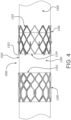
- one or more of the joints 1214 and the frame members 1212 deform such that the apertures or voids 1216 generally define an elongated diamond shape (e.g., as shown generally in FIG. 4 ).
- the apertures or voids 1216 Upon re-expanding the valve frame subcomponent 1200 to a larger diameter during deployment at a treatment site, the apertures or voids 1216 re-expand to define the generally wider diamond shape.
- the interconnected frame members 1212 may be arranged in a number of alternative patterns without departing from the spirit or scope of the disclosure. That is, a number of alternative patterns are envisioned where the arrangement of frame members 1212 is configured in such a manner as to provide for an valve frame subcomponent 1200 that can be compressed to a smaller diameter for transcatheter delivery and subsequently expanded (or allowed to expand) to a larger diameter at a treatment site during deployment of the prosthetic valve 1000. Accordingly, the disclosure should not be limited to arrangements of the frame members 1212 that define diamond-shaped apertures or voids 1216.
- a framework of the valve frame subcomponent 1200 can define any number of features, repeatable or otherwise, such as geometric shapes and/or linear or meandering series of sinusoids. Geometric shapes can comprise any shape that facilitates circumferential compressibility and expandability.
- valve frame subcomponent 1200 may comprise or otherwise be formed from a cut tube, or any other element suitable for the particular purpose of the valve frame subcomponent 1200 as described herein.
- the valve frame subcomponent 1200 may be etched, cut, laser cut, or stamped into a tube or a sheet of material, with the sheet then formed into a substantially cylindrical structure.
- an elongated material such as a wire, bendable strip, or a series thereof, can be bent or braided and formed into a substantially cylindrical structure wherein the walls of the cylinder comprise an open framework that is compressible to a smaller diameter in a generally uniform and circumferential manner and expandable to a larger diameter as illustrated and described herein.
- the valve frame subcomponent 1200 may comprise, such as, but not limited to, any elastically deformable metallic or polymeric biocompatible material, in accordance with embodiments.
- the valve frame subcomponent 1200 may comprise a shape-memory material, such as nitinol, a nickel-titanium alloy.
- Other materials suitable for the valve frame subcomponent 1200 include, but are not limited to, other titanium alloys, stainless steel, cobalt-nickel alloy, polypropylene, acetyl homopolymer, acetyl copolymer, other alloys or polymers, or any other biocompatible material having adequate physical and mechanical properties to function as a valve frame subcomponent 1200 as described herein.
- valve frame subcomponent 1200 is elastically deformable so as to be self-expanding under spring loads, as those of skill will appreciate.
- the valve frame subcomponent 1200 is plastically deformable so as to be mechanically expanded such as with a balloon, as those of skill will appreciate.
- the valve frame subcomponent 1200 is plastically deformable as well as elastically deformable. That is, in some examples, the valve frame subcomponent 1200 includes one or more elastically deformable components or features and one or more plastically deformable components or features.
- the examples of the valve frame subcomponent 1200 presented herein are not to be limited to a specific design or mode of expansion.
- the valve frame subcomponent 1200 comprises a shape memory material operable to flex under load and retain its original shape when the load is removed, thus allowing the valve frame subcomponent 1200 to self-expand from a compressed shape to a predetermined shape.
- the valve frame subcomponent 1200 and the anchor frame subcomponent 1100 may comprise the same or different materials.
- the valve frame subcomponent 1200 is plastically deformable to be expanded by a balloon. In another embodiment the valve frame subcomponent 1200 is elastically deformable so as to be self-expanding.
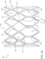
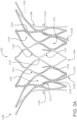
- FIG. 3A is a side view of the anchor frame 1101.
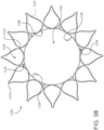
- FIG. 3B is an axial view of the anchor frame 1100.
- the anchor frame subcomponent 1100 includes an anchor frame 1101.
- the side of the anchor frame 1101 may be at least partially covered, such as with a film or fabric, not shown for clarity, suitable for a particular purpose, such as to restrict fluid from passing through the anchor frame 1101, or to encourage tissue ingrowth at the implant site.
- the following examples are suitable especially for a transcatheter application, but are also suitable for a surgical application.
- the anchor frame subcomponent 1100 comprises a shape memory material operable to flex under load and retain its original shape when the load is removed, thus allowing the anchor frame subcomponent 1100 to self-expand from a compressed shape to a predetermined larger shape.
- the anchor frame subcomponent 1100 may comprise the same or different materials as the valve frame subcomponent 1200.
- the anchor frame subcomponent 1100 is plastically deformable to be expanded by a balloon.
- the anchor frame subcomponent 1100 is elastically deformable so as to be self-expanding.
- the interstage 1300 includes a conduit 1302 that couples to an anchor frame distal end 1104 of the anchor frame 1100 at an awakestage proximal end 1314 and couples to a leaflet frame proximal end 1202 at an interstage distal end 1316.
- the conduit 1302 may comprise any suitable material known in the art.
- the conduit 1302 may be a film, fabric, among others.
- film is use throughout this disclosure, it is understood that the term includes film, fabric, and other suitable materials.
- the interstage 1300 further comprises a nesting retention element 1330, such as shown in FIGS. 7C-7E, to be described below, that is operable to retain the valve frame subcomponent 1200 as nested in the anchor frame subcomponent 1100.
- nesting retention elements 1330 are provided below.
- the nesting retention elements 1330 may be elongated elements that bias the interstage 1300 in the nesting position.
- the nesting retention elements 1330 are caused to evert during the deployment process of translating the valve frame subcomponent 1200 into the anchor frame subcomponent 1100.
- the nesting retention elements 1330 are provided with a predetermined stiffness or other property sufficient to permit eversion during deployment but not under normal biological forces.
- the nesting retention elements 1330 are sized such that, when the anchor frame subcomponent 1100 is expanded and the valve frame subcomponent is compressed, the nesting retention elements 1330 are able to rotate lengthwise from a forward facing orientation to a backward facing orientation.
- the nesting retention elements 1330 When the valve frame subcomponent 1200 is expanded, the nesting retention elements 1330 have a profile or length that prevents the nesting retention elements 1330 from rotating or flipping back to a forward facing orientation. In other words, the gap between the anchor frame subcomponent 1100 and the valve frame subcomponent 1200 is too narrow to allow end over end rotation of the nesting retention elements 1330.
- the nesting retention elements 1330 are provided with a predetermined stiffness or other property sufficient to prevent eversion of the nesting retention elements 1330 within the gap between the anchor frame subcomponent 1100 and the valve frame subcomponent 1200 under normal biological forces.
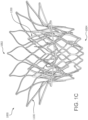
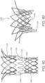
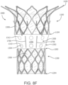
- FIG. 1C is a perspective view showing the valve frame subcomponent 1200 and an anchor frame subcomponent 1100 of a prosthetic valve 1000 in a nested configuration, also referred to as the deployed position, leaflets not shown for clarity.
- FIG. 1B is a front view of the valve frame subcomponent 1200 and the anchor frame subcomponent 1100 of the prosthetic valve 1000 of FIG. 1C . In both FIGS. 1B and 1C , the leaflets and any film, as will be discussed below, are not shown for clarity.
- FIG. 1D is an axial view of the valve frame subcomponent 1200 and the anchor frame subcomponent 1100 of the prosthetic valve 1000 of FIG. 1A , showing the leaflets 1210. In the axial view of FIG.
- valve frame subcomponent 1200 three leaflets 1210 are shown coupled to the valve frame subcomponent 1200. It is in this deployed position that the prosthetic valve 1000 remains in the prosthetic valve orifice to function as a prosthetic valve.
- the anchor frame subcomponent 1100 and the valve frame subcomponent 1200 are longitudinally offset and generally coaxial relative to one another.
- a prosthetic valve 1000 includes an anchor frame 1102, and a valve frame 1202.
- the valve frame subcomponent 1200 onto which leaflets 1020 are coupled, is positioned at least partially within the anchor frame subcomponent 1100.
- the prosthetic valve 1000 has a proximal end or proximal portion 1002 and a distal end or distal portion 1004.
- the proximal portion 1002 of the prosthetic valve 1000 when deployed within the body, is positioned upstream or retrograde relative to the distal portion 1004 of the prosthetic valve 1000, which is positioned downstream or antegrade relative to the proximal portion 1002.
- the anchor frame subcomponent 1100 and the valve frame subcomponent 1200 are coupled together.
- a interstage 1300 is disposed within and/or about the anchor frame subcomponent 1100 and the valve frame subcomponent 1200.
- the interstage 1300 is a contiguous film that at least extends between and operates to couple the anchor frame subcomponent 1100 and the valve frame subcomponent 1200 to one another.
- the interstage 1300 extends not only between but also over or within either or both of the anchor frame subcomponent 1100 and the valve frame subcomponent 1200.
- the interstage portion 1302. The portion of the interstage 1300 that extends between and couples with the anchor frame subcomponent 1100 and the valve frame subcomponent 1200 is referred herein as the interstage portion 1302.
- the interstage 1300 is formed from a generally tubular material and at least partially covers one or more of the anchor frame subcomponent 1100 and the valve frame subcomponent 1200.
- the interstage 1300 is formed by wrapping a film over and around a cylindrical mandrel, with either or both of the anchor frame subcomponent 1100 and the valve frame subcomponent 1200 being slid over and bonded thereto to the inner surface of the frames.
- the interstage 1300 is formed by wrapping the film over and around either or both of the anchor frame subcomponent 1100 and the valve frame subcomponent 1200 and bonded thereto to the outer surface of the frames.
- anchor frame subcomponent 1100 and the valve frame subcomponent 1200 are comprised of metal
- Such configurations minimize the potential for metals of varying composition to react with one another or corrode.
- the interstage 1300 is generally any sheet-like material that is biologically compatible and configured to couple to the anchor frame subcomponent 1100 and the valve frame subcomponent 1200.
- the biocompatible material is a film that is not of a biological source and that is sufficiently flexible and strong for the particular purpose, such as a biocompatible polymer.
- the film comprises a biocompatible polymer (e.g., ePTFE).
- the film is a composite of two or more materials.
- the film may comprise one or more of a membrane, composite material, or laminate.
- the construction of and materials used in the film are such that the interstage 1300 promotes cellular ingrowth, adhesion, and/or attachment.
- the interstage 1300 is constructed in a manner that promotes the ingrowth of tissue into one or more portions of the film. It will be appreciated that cellular ingrowth further increases sealing of the valve with the prosthetic valve orifice and helps minimize para-valvular leakage, that is, leakage between the prosthetic valve and the tissue into which it is coupled.
- the valve frame subcomponent 1200 additionally supports or otherwise includes a valve structure.
- the valve structure includes one or more leaflets 1210 as shown in FIG. 1D .
- leaflets 1210 A variety of mechanical valve, biological leaflet, and synthetic leaflet designs are known in the medical technology arts, any of which may be incorporated into the valve frame subcomponent 1200 of the present disclosure. Examples of suitable leaflet constructions and methods of attachment to valve frame subcomponents are illustrated and described in U.S. Patent Application Nos. 13/833,650 , 14/973,589 , and 14/622,599 , the contents of each of which are incorporated herein by reference. Further examples of suitable leaflet material are presented below.
- valve or leaflets 1020 are coupled to the interior surface 1206 of the valve frame subcomponent 1200.
- a film that comprises a leaflet is contained between the valve frame subcomponent 1200 and the anchor frame subcomponent 1100 and extends through a leaflet window defined by the valve frame subcomponent 1200.
- Such a configuration minimizes a potential for the leaflet to peel or delaminate, as compared to configurations where the leaflets are coupled to the interior surface 1206 of the valve frame subcomponent 1200.
- one or more portions of the leaflets are wrapped about one or more portions of the valve frame subcomponent 1200.
- the valve frame subcomponent 1200 includes one or more projections and the leaflets 1020 include one or more apertures that are configured to be disposed about the one or more projections.
- the valve frame subcomponent 1200 is nestable within the anchor frame subcomponent 1100.
- the anchor frame subcomponent 1100 and the valve frame subcomponent 1200 are sized and shaped in a manner that provides for the valve frame subcomponent 1200 being coaxially disposable or receivable at least partially within the anchor frame subcomponent 1100.
- the anchor frame subcomponent 1100 is configured such that a portion of (or alternatively all of) the valve frame subcomponent 1200 can be received by or otherwise positioned within a space defined by the anchor frame subcomponent 1100.
- the valve frame subcomponent 1200 is sized such that a diameter of the exterior surface of the valve frame subcomponent 1200 is less than a diameter of the interior surface of the anchor frame subcomponent 1100. In some examples, a diameter of the exterior surface of the valve frame subcomponent 1200 is in a range of between seventy five percent (75%) and ninety percent (90%) of a diameter of the interior surface of the anchor frame subcomponent 1100. In some examples, a diameter of the exterior surface of the valve frame subcomponent 1200 is seventy five percent (75%) or less than a diameter of the interior surface of the anchor frame subcomponent 1100.
- valve frame subcomponent 1200 can be received within the anchor frame subcomponent 1100.
- anchor frame subcomponent 1100 can deform, such as, but not limited to being out of round or generally oval-shaped, to accommodate or otherwise conform to the prosthetic valve orifice without causing a deformation of the valve frame subcomponent 1200.
- the prosthetic valve 1000 provides a valve frame subcomponent 1200 that essentially floats within the anchor frame subcomponent 1100 and does not directly couple with a prosthetic valve orifice.
- the anchor frame subcomponent 1100 may conform to the shape of the prosthetic valve orifice whereas the valve frame subcomponent 1200 does not conform to the shape of the prosthetic valve orifice.
- valve frame subcomponent 1200 remains cylindrical or at a preferred geometrical configuration so as to present the leaflets 1210 with a geometrically stable platform ensuring proper leaflet function, including coaptation and opening dynamics. It is appreciated that these benefits associated with the valve frame subcomponent 1200 not needing to conform to the prosthetic valve orifice may be realized in either transcatheter or surgical placement of the prosthetic valve 1000.
- the prosthetic valve 1000 is configured such that the anchor frame subcomponent 1100 and the valve frame subcomponent 1200 can be nested in-situ after the anchor frame subcomponent 1100 and the valve frame subcomponent 1200 are deployed at a treatment site in a patient's anatomy. That is, in various embodiments, the prosthetic valve 1000 can be delivered to a treatment region within a patient's anatomy with the anchor frame subcomponent 1100 and the valve frame subcomponent 1200 longitudinally offset relative to one another and subsequently nested with one another at the treatment site.
- the prosthetic valve 1000 is loaded onto a delivery catheter with the anchor frame subcomponent 1100 and the valve frame subcomponent 1200 longitudinally offset relative to one another which presents a lower profile or diameter than if the prosthetic valve 1000 were to be loaded onto the delivery catheter in the nested configuration.
- a lower delivery profile of a transcatheter delivered prosthetic valve has well recognized advantages, including easier advancement though vessels.
- valve frame subcomponent 1200 may also be realized in surgical placement of the prosthetic valve 1000.
- the anchor frame subcomponent 1100 may be more easily sutured into the prosthetic valve orifice without the valve frame subcomponent 1200 being within the anchor frame subcomponent 1100 and in close proximity to the suturing procedure lessening the chance of needle damage to the leaflets.
- the anchor frame subcomponent 1100 and the valve frame subcomponent 1200 are operable to nest with one another by telescoping the anchor frame subcomponent 1100 and the valve frame subcomponent 1200 relative to one another in-situ.
- the valve frame subcomponent 1200 and the anchor frame subcomponent 1100 are sized such that the valve frame subcomponent 1200 can be receive within the interior region 1110 of the anchor frame subcomponent 1100.
- the anchor frame subcomponent 1100, the valve frame subcomponent 1200, and the film 1300 are each configured to be compressed or collapsed to a delivery profile and then reexpanded in-situ to provide for transcatheter delivery of the prosthetic valve 1000, as discussed in greater detail below.
- FIGS. 2A and 2B are side and axial views, respectively, of the anchor frame subcomponent 1100, in accordance with an embodiment.
- the anchor frame subcomponent 1100 is a generally tubular member having a proximal end 1102, a distal end 1104, an interior surface 1106, and an exterior surface 1108.
- the anchor frame subcomponent 1100 defines an interior region 1110.
- the interior region 1110 is a generally cylindrical void defined between the proximal and distal ends 1102 and 1104, and the interior surface 1106 of the anchor frame subcomponent 1100.
- the interior region 1110 may adopt an irregular cross section, depending on the geometry of the prosthetic valve orifice.
- the anchor frame subcomponent 1100 is configured to couple to a native valve orifice. Accordingly, in various examples, a diameter of the anchor frame subcomponent 1100 (e.g., a diameter of an interior or exterior surface of the anchor frame subcomponent 1100) is sized in accordance with patient anatomy. It will be appreciated that nonlimiting examples of anchor frame subcomponents 1100 can be provided with a diameter (e.g., a diameter of an interior or exterior surface of the anchor frame subcomponent 1100) in a range of between twenty five (25) millimeters and fifty (50) millimeters, depending on a patient's anatomy.
- anchor frame subcomponents 1100 having diameters e.g., a diameter of an interior or exterior surface of the anchor frame subcomponent 1100
- diameters e.g., a diameter of an interior or exterior surface of the anchor frame subcomponent 1100
- 50 millimeters are also envisioned and fall within the scope of the present disclosure, depending on patient anatomy.
- the anchor frame subcomponent 1100 defines a cylindrical or tubular mesh having a framework defining apertures.
- the anchor frame subcomponent 1100 includes a plurality of frame members 1112 that are interconnected and arranged in one or more patterns. In some examples, these patterns repeat one or more times.
- the frame members 1112 are arranged and interconnected such that the anchor frame subcomponent 1100 includes a plurality of patterned rows. In various examples, the frame members 1112 are connected to one another at various joints 1114.
- these joints 1114 operate as flex points so as to provide a preferential flexing location for the anchor frame subcomponent 1100 to flex when compressed to a smaller delivery diameter and when forces from the surrounding anatomy act to compress the anchor frame subcomponent 1100 during normal operation after delivery and deployment of the prosthetic valve 1000.
- a flex point or joint 1114 comprises a site on the anchor frame subcomponent 1100 that undergoes a high degree of bending.
- the joints 1114 may comprise a geometry, structural modification or material modification, among others, that biases the anchor frame subcomponent 1100 to bend at the flex point or joint 1114 when compressed.
- one or more closed cell apertures or voids 1116 are defined between the joints 1114 and the interconnected frame members 1112 of the anchor frame subcomponent 1100. In some examples, these apertures or voids 1116 extend from the exterior surface 1108 to the interior surface 1106 of the anchor frame subcomponent 1100. As illustrated in the embodiments of FIGS. 2A and 2B , one or more of the apertures or voids 1116 define a diamond shape when the anchor frame subcomponent 1100 is in a deployed configuration.
- one or more of the joints 1114 and the frame members 1112 deform such that the apertures or voids 1116 generally define an elongated diamond shape (e.g., as shown generally in FIG. 4A).
- the apertures or voids 1116 Upon re-expanding the anchor frame subcomponent 1100 to a larger diameter during deployment at a treatment site, the apertures or voids 1116 re-expand to define the generally wider diamond shape.
- the anchor frame subcomponent 1100 defines a flange or a flared portion at its proximal end 1102 that flares or tapers radially outward when in the deployed configuration.
- the proximal end 1102 is flared or otherwise tapered radially outward when in the deployed configuration. That is, as shown, the proximal end 1102 of the anchor frame subcomponent 1100 has a larger deployed diameter than does the distal end 1104 of the anchor frame subcomponent 1100.
- such a configuration operates to minimize migration risks and helps facilitate abutment of the anchor frame subcomponent 1100 with native tissue at the treatment site.
- a framework of the anchor frame subcomponent 1100 can define any number of features, repeatable or otherwise, such as geometric shapes and/or linear or meandering series of sinusoids. Geometric shapes can comprise any shape that facilitates circumferential compressibility and expandability of the anchor frame subcomponent 1100.
- the arrangement of frame members 1112 is configured in such a manner as to provide for an anchor frame subcomponent 1100 that can be compressed to a smaller diameter for transcatheter delivery and subsequently expanded (or allowed to expand) to a larger diameter at a treatment site during deployment of the prosthetic valve 1000. Accordingly, the disclosure should not be read as being limited to arrangements of the frame members 1112 that define diamond-shaped apertures or voids 1116.
- the anchor frame subcomponent 1100 may comprise or otherwise be formed from a cut tube, or any other element suitable for the particular purpose of the anchor frame subcomponent 1100 as described herein.
- the anchor frame subcomponent 1100 may be etched, cut, laser cut, or stamped into a tube or a sheet of material, with the sheet then formed into a substantially cylindrical structure.
- an elongated material such as a wire, bendable strip, or a series thereof, can be bent or braided and formed into a substantially cylindrical structure wherein the walls of the cylinder comprise an open framework that is compressible to a smaller diameter in a generally uniform and circumferential manner and expandable to a larger diameter as illustrated and described herein.
- the anchor frame subcomponent 1100 can comprise any metallic or polymeric biocompatible material.
- the anchor frame subcomponent 1100 can comprise a material, such as, but not limited to nitinol, cobalt-nickel alloy, stainless steel, or polypropylene, acetyl homopolymer, acetyl copolymer, ePTFE, other alloys or polymers, or any other biocompatible material having adequate physical and mechanical properties to function as described herein.
- the anchor frame subcomponent 1100 is elastically deformable so as to be self-expanding under spring loads, as those of skill will appreciate.
- the anchor frame subcomponent 1100 is plastically deformable so as to be mechanically expanded such as with a balloon, as those of skill will appreciate.
- the anchor frame subcomponent 1100 is plastically deformable as well as elastically deformable. That is, in some examples, the anchor frame subcomponent 1100 includes one or more elastically deformable components or features and one or more plastically deformable components or features.
- the examples of the anchor frame subcomponent 1100 presented herein are not to be limited to a specific design or mode of expansion.
- the anchor frame subcomponent 1100 is configured to provide positive engagement with an implant site to firmly anchor the prosthetic valve 1000 to the site.
- the anchor frame subcomponent 1100 includes one or more tissue engagement features 1118 that are configured to engage one or more regions of tissue at the prosthetic valve orifice surrounding the prosthetic valve 1000.
- the tissue engagement features 1118 comprise one or more barbs or tissue anchors.
- the one or more tissue engagement features 1118 project away from the interior and/or exterior surfaces 1106 and 1108 of the anchor frame subcomponent 1100, radially outward from a longitudinal axis of the anchor frame subcomponent 1100, and toward the tissue surrounding the prosthetic valve 1000.
- the tissue engagement features 1118 are operable to project away from the anchor frame subcomponent 1100 when the anchor frame subcomponent 1100 is deployed (e.g., when a constraining member is withdrawn or otherwise removed).
- the tissue engagement features 1118 are operable to engage the tissue proximate the anchor frame subcomponent 1100 such that the tissue engagement features 1118 secure the anchor frame subcomponent 1100 to the surrounding tissue, as will be discussed in greater detail below.
- the tissue engagement features project away from an exterior surface of the anchor frame subcomponent in a range of between thirty (30) and sixty (60) degrees. In some such examples, the tissue engagement features project away from an exterior surface of the anchor frame subcomponent at an angle of approximately forty five (45) degrees, though other configurations are contemplated and fall within the scope of the present application. Generally, any angle of projection is suitable provided that the tissue engagement features operate for their intended purpose of engaging the tissue surrounding the anchor frame subcomponent and causing the anchor frame subcomponent to be secured to the surrounding tissue.
- tissue engagement features may include a variety of different lengths (depending on the angle from which they project from the anchor frame subcomponent), it will be appreciated that the tissue engagement features are of a length suitable for engaging tissue and securing the anchor frame subcomponent to the surrounding tissue, but not so long as to risk detrimental damage to the prosthetic valve orifice.
- One nonlimiting example configuration includes tissue engagement features projecting from the anchor frame subcomponent in a range of between thirty (30) and sixty (60) degrees and having a length of between fifty (50) micron and two hundred (200) micron.
- the tissue engagement features 1118 are positioned along the anchor frame subcomponent such that they are operable to engage tissue proximate the anchor frame subcomponent 1100 when the anchor frame subcomponent 1100 is expanded in-situ.
- the tissue engagement features 1118 may be arranged in one or more rows along a longitudinal axis of the anchor frame subcomponent 1100. That is, in various examples, anchor frame subcomponent may include a first set (or row) of anchors and a second set (or row) of anchors longitudinally offset relative to the first set of anchors. In one such example, the first set of anchors is more proximate the distal end 1104 of the anchor frame subcomponent 1100 than is the second set of anchors.
- the one or more tissue engagement features 1118 are circumferentially arranged about the anchor frame subcomponent 1100. In some examples, the one or more tissue engagement features 1118 are evenly dispersed about the circumference of the anchor frame subcomponent. For example, the tissue engagement features 1118 are dispersed about the frame and are offset from one another by ninety (90) degrees depending on the number of anchors. Alternatively, the tissue engagement features 1118 may be dispersed about the frame and offset from one another by sixty (60) degrees depending on the number of anchors. Generally, the angular offset between the anchors is a function of the number of anchors dispersed about the anchor frame subcomponent 1100, as those of skill will appreciate. In some examples, the angular offset between the anchors is additionally or alternatively based on an arrangement or pattern of the frame members 1112.
- tissue engagement features 1118 project away from the anchor frame subcomponent 1100 when the anchor frame subcomponent 1100 is in the deployed configuration
- the tissue engagement features 1118 are stowed or do not otherwise project away from the anchor frame subcomponent 1100 when the anchor frame subcomponent 1100 is compressed in the delivery configuration.
- the tissue engagement features 1118 are stowable during delivery and are configured to transition to a deployed configuration where they project away from the anchor frame subcomponent 1100.
- a constraining member disposed about the anchor frame subcomponent 1100 during delivery facilitates stowing of the tissue engagement features 1118.
- the tissue engagement features 1118 are stowed in associated apertures or voids 1116 of the anchor frame subcomponent 1100.
- the tissue engagement features 1118 are integral to the anchor frame subcomponent 1100.
- one or more of the tissue engagement features 1118 are formed in conjunction with and from the same material as the frame members 1112.
- one or more of the tissue engagement features 1118 are separate components additionally or alternatively coupled or attached to the anchor frame subcomponent 1100.
- some non-limiting examples include crimping and/or welding one or more tissue engagement features to the anchor frame subcomponent 1100.
- the flared or tapered portion of the anchor frame subcomponent 1100 is configured to deflect when the anchor frame subcomponent 1100 is in the delivery configuration.
- the flared or tapered proximal end 1102 of the anchor frame subcomponent 1100 is deflected such that the anchor frame subcomponent 1100 has a substantially uniform delivery profile along its longitudinal axis.
- one or more constraining members are disposed about the anchor frame subcomponent 1100 in the delivery configuration.
- a first constraining member is disposed about the proximal end 1102 of the anchor frame subcomponent 1100 and a second constraining member is disposed about the distal end 1104 of the anchor frame subcomponent 1100, as will be described in more detail when referring to FIGS. 9-16 .
- Each constraining member may extend about an exterior surface 1108 of the anchor frame subcomponent 1100, or one or more of the constraining members may be woven through one or more portions of the film disposed about the anchor frame subcomponent 1100.
- one or more of the constraining members extending about the exterior surface 1108 may extend through a portion of the film, and extend along a portion of the interior surface 1106 of the anchor frame subcomponent 1100, and then extend back through the film to the exterior surface 1108 and extend therearound.
- the one or more constraining members individually or collectively operate to constrain the anchor frame subcomponent 1100 in a delivery configuration. In various examples, this includes one or more constraining members individually or collectively constrains the flange or flared portion of the anchor frame subcomponent 1100 in a delivery configuration.
- a removable constraining sheath is disposed about the flange or flared portion of the anchor frame subcomponent 1100 in a delivery configuration.
- the delivery system may include one or more flange stops (see e.g., flange stop 1562 in FIG. 16 ).
- the flange stops operate to constrain the anchor frame subcomponent 1100 from translating proximally as a constraining sheath (see, e.g., constraining sheath 1564 in FIG. 16 ) is withdrawn from one or more of the anchor frame subcomponent 1100 and the valve frame subcomponent 1200.
- one or more constraining members individually or collectively constrain the tissue engagement features to a delivery (undeployed) configuration.
- a removable constraining sheath is disposed about the tissue engagement features of the anchor frame subcomponent 1100.
- the one or more constraining members are removed from the anchor frame subcomponent 1100 during deployment of the anchor frame subcomponent 1100.
- the constraining members includes a fiber.
- the constraining members includes a wire.
- one or more lockwires engage a first end of the one or more constraining members at or proximate the anchor frame subcomponent 1100 such that tension can be applied to an opposing second end of the one or more constraining members.
- tensioning the one or more constraining members operates to maintain the anchor frame subcomponent 1100 in the delivery configuration.
- one or more constraining members are disposed about the valve frame subcomponent 1200 in the delivery configuration, as will be described in more detail when referring to FIGS. 9-16 .
- a third constraining member is disposed about the proximal end 1202 of the valve frame subcomponent 1200 and a fourth constraining member is disposed about the distal end 1204 of the valve frame subcomponent 1200.
- Each constraining member may extend about an exterior surface 1208 of the valve frame subcomponent 1200.
- one or more of the constraining members may be woven through one or more portions of the film disposed about the valve frame subcomponent 1200.
- one or more of the constraining members extending about the exterior surface 1208 may extend through a portion of the film, and extend along a portion of the interior 1206 of the valve frame subcomponent 1200, and then extend back through the film to the exterior surface 1206 and extend therearound.
- the one or more constraining members individually or collectively operate to constrain the valve frame subcomponent 1200 in a delivery configuration.
- one or more constraining members individually or collectively constrain the tissue retention features to a delivery (undeployed) configuration.
- a removable constraining sheath is disposed about the tissue engagement features of the valve frame subcomponent 1200.
- the removable constraining sheath may be disposed about both the valve frame subcomponent 1200 and the anchor frame subcomponent 1100 (see discussion above).
- the one or more constraining members are removed from the valve frame subcomponent 1200 during deployment of the valve frame subcomponent 1200.
- the constraining members includes a fiber.
- the constraining members includes a wire.
- one or more lockwires engage a first end of the one or more constraining members at or proximate the valve frame subcomponent 1200 such that tension can be applied to an opposing second end of the one or more constraining members.
- tensioning the one or more constraining members operates to maintain the valve frame subcomponent 1200 in the delivery configuration.
- the anchor frame subcomponent 1100 in addition to facilitating a positive engagement with an implant site to anchor the prosthetic valve 1000 to the surrounding tissue, additionally or alternatively includes one or more mechanisms that facilitate a positive engagement with the valve frame subcomponent 1200 upon nesting the anchor frame subcomponent 1100 and the valve frame subcomponent 1200.
- the anchor frame subcomponent 1100 includes one or more interlock features 1120 that project into the interior region 1110 of the anchor frame subcomponent 1100. These interlock features 1120 are configured to engage the nested valve frame subcomponent 1200 and maintain a relative axial position (or at least minimize relative axial movement) between the anchor frame subcomponent 1100 and the valve frame subcomponent 1200.
- the interlock features 1120 are structures that project or otherwise extend away from the interior and exterior surfaces 1106 and 1108 of the anchor frame subcomponent 1100 and toward the interior region 1110 defined by the anchor frame subcomponent 1100.
- the one or more interlock features 1120 are in the form of one or more tabs.
- the one or more interlock features 1120 have a free end 1122 and a base 1124.
- the free end 1122 is an end that is not otherwise coupled to or mated with the anchor frame subcomponent 1100.
- the base 1124 is generally the portion of the interlock feature that couples to or is otherwise integral with the anchor frame subcomponent 1100.
- the free end 1122 is operable to move relative to the anchor frame subcomponent 1100, while the base 1124 is coupled to the anchor frame subcomponent 1100.
- the non-limiting exemplary interlock features 1120 illustrated in FIGS. 2A and 2B are each elongate elements.
- the free end 1122 is illustrated as being a generally blunt or round end, though the free end 1122 or the interlock feature 1120, generally, may alternatively be pointed or possess other suitable geometry such as a curved shape (e.g., an s-shape).
- a curved shape e.g., an s-shape
- other geometries suitable for engaging the valve frame subcomponent 1200 when it is nested with the anchor frame subcomponent 1100 in the manner illustrated and described herein are envisioned and may be utilized without departing from the spirit or scope of the disclosure.
- the free end 1122 of the interlock feature 1120 is shaped such that it is operable to slide along the exterior of the valve frame subcomponent 1200.
- a film e.g., film 1300 covers one or more portions of the valve frame subcomponent 1200.
- the free end 1122 of the interlock feature 1120 is shaped and sized in a manner that allows the interlock feature 1120 to slide along the exterior of the valve frame subcomponent 1200 without binding.
- the interlock feature 1120 is approximately six hundred micron in length and is angled at approximately forty five (45) degrees relative to the interior of the anchor frame subcomponent. It will be appreciated, however, that a number of angle and length configurations are contemplated and fall within the scope of the present application.
- the interlock features 1120 may be arranged in one or more rows along a longitudinal axis of the anchor frame subcomponent 1100. That is, in various examples, anchor frame subcomponent 1100 may include a first set (e.g., a row) of interlock features and a second set (e.g., a row) of interlock features longitudinally offset relative to the first set of interlock features. In one such example, the first set of interlock features is more proximate the distal end 1104 of the anchor frame subcomponent 1100 than is the second set of interlock features.
- the interlock features 1120 are configured to project away from the anchor frame subcomponent 1100 when the anchor frame subcomponent 1100 is in the deployed configuration, the interlock features 1120 are stowed or do not otherwise project away from the anchor frame subcomponent 1100 when the anchor frame subcomponent 1100 is compressed in the delivery configuration.
- the interlock features 1120 are configured to transition between a stowed or delivery configuration and a projecting or deployed configuration.
- the interlock features 1120 are resilient members that are configured to deflect under certain conditions.
- the interlock features 1120 are configured to engage the valve frame subcomponent 1200 as it is nested with the anchor frame subcomponent 1100 in-situ. In some examples, as discussed further below, the interlock features 1120 temporarily deflect from an engaged position to enable nesting of the valve frame subcomponent 1200 with the anchor frame subcomponent 1100, and subsequently return to the engaged position after the valve frame subcomponent 1200 is nested with the anchor frame subcomponent 1100. In various examples, the interlock features 1120 return to the engaged position upon the valve frame subcomponent 1200 being proximally advanced a suitable amount relative to the anchor frame subcomponent 1100.
- the interlock features 1120 of the anchor frame subcomponent 1100 are operable to adopt an engaged position where they engage the valve frame subcomponent 1200 and minimize relative axial translation between the valve frame subcomponent 1200 and the anchor frame subcomponent 1100 upon proximally advancing the valve frame subcomponent 1200 a designated amount relative to the anchor frame subcomponent 1100.
- a delivery catheter upon which the anchor frame subcomponent 1100 is loaded during delivery causes stowing of the interlock features 1120.
- the interlock features 1120 are integral to the anchor frame subcomponent 1100.
- one or more of the interlock features 1120 are formed in conjunction with and from the same material as the frame members 1112.
- one or more of the interlock features 1120 are additionally or alternatively coupled to the anchor frame subcomponent 1100. That is, in some examples, one or more interlock features 1120 are additionally or alternatively attached to the anchor frame subcomponent 1100.
- the one or more interlock features 1120 are circumferentially arranged about the anchor frame subcomponent 1100. In some examples, the one or more interlock features 1120 are evenly dispersed about the circumference of the anchor frame subcomponent.
- the angular offset between the anchors is generally a function of one or more of the arrangement of the frame members 1112 and the number of anchors dispersed about the anchor frame subcomponent 1100, as those of skill will appreciate.
- valve frame subcomponent 1100 includes one or more interlock features (not shown) that extend from the exterior surface 1208 away from the interior surface 1206 of the valve frame subcomponent 1200 and that are operable to engage the anchor frame subcomponent 1100 upon nesting of the anchor frame subcomponent 1100 and the valve frame subcomponent 1200.
- the interlock features of the valve frame subcomponent 1200 are positionable at a proximal end 1202, a distal end 1204, or some position between the proximal and distal ends 1202 and 1204 provided that the interlock features of the valve frame subcomponent are operable to engage the anchor frame subcomponent 1100 upon nesting of the anchor frame subcomponent 1100 and the valve frame subcomponent 1200.
- the interlock features of the valve frame subcomponent are deflectable and stowable in a manner similar to the interlock features 1120 of the anchor frame subcomponent 1100, as previously described.
- FIGS. 3A and 3B are side and axial views, respectively, of the valve frame subcomponent 1200, in accordance with an embodiment.
- the valve frame subcomponent 1200 is generally cylindrical or tubular member having a proximal end 1202, a distal end 1204, an interior surface 1206, and an exterior surface 1208.
- the valve frame subcomponent 1200 defines an interior region 9999.
- interior region is a generally cylindrical void defined between the proximal and distal ends 1202 and 1204, and the interior surface 1206 of the valve frame subcomponent 1200.
- the valve frame subcomponent 1200 is configured to be received within at least a portion of the anchor frame subcomponent 1100, as mentioned above.
- valve frame subcomponents 1200 can be provided with a diameter (e.g., a diameter of an interior or exterior surface of the valve frame subcomponent 1200) in a range of between twenty (20) millimeters and thirty (30) millimeters, depending on a patient's anatomy.
- a diameter e.g., a diameter of an interior or exterior surface of the valve frame subcomponent 1200 in a range of between twenty (20) millimeters and thirty (30) millimeters, depending on a patient's anatomy.
- the valve frame subcomponent 1200 includes one or more features that operate to grab or otherwise interface with native valve tissue (e.g., native leaflet tissue) or tissue surrounding the native valve being replaced.
- native valve tissue e.g., native leaflet tissue
- the valve frame subcomponent 1200 includes one or more tissue retention features 1218 (also referred to herein as tissue graspers).
- tissue retention features 1218 are projections of the valve frame subcomponent 1200 that are configured to interface with the patient's native tissue associated with the native valve.
- the one or more tissue retention features 1218 are configured to interface with one or more of the native leaflets associated with the native valve.
- mitral valve repair/augmentation procedures are discussed herein, it will be appreciated that the scope of the disclosure applies to repair/augmentation of the atrioventricular (AV) valves and the semilunar (SL) valves. The disclosure should therefore not be interpreted as being limited to mitral valve repair/augmentation.
- the one or more tissue retention features 1218 have a free end 1220 and a base 1222.
- the free end 1220 is an end that is not otherwise coupled to or mated with the valve frame subcomponent 1200.
- the base 1222 includes one or more portions of the tissue retention feature 1218 that couple to or are otherwise integral with the valve frame subcomponent 1200.
- the free end 1220 is operable to move relative to the valve frame subcomponent 1200, while the base 1222 is coupled to the valve frame subcomponent 1200.
- another non-limiting exemplary tissue retention feature includes an end coupled to or otherwise integral with the valve frame subcomponent 1200 and a plurality of free ends extending from the end coupled to the valve frame subcomponent 1200.
- Another non-limiting exemplary tissue retention feature includes a barb or similar feature having opposed single ends coupled to or otherwise integral with the valve frame subcomponent 1200.
- the profile of the free end 1220 of the tissue retention feature 1218 is one generally well suited for penetrating tissue or penetrating between tissue of the surrounding anatomy.
- the tissue retention features 1218 have a first side 1228 and a second side 1230. As shown in FIGS. 3A and 3B , the first side 1228 faces the exterior surface 1208 of the valve frame subcomponent 1200, and the second side 1230 faces away from the exterior surface 1208 of the valve frame subcomponent. In some examples, a void or open space region is defined between the first side 1228 and the exterior surface 1208 of the valve frame subcomponent 1200. In various examples, as discussed below, this open space region between the first side 1228 and the exterior surface 1208 of the valve frame subcomponent 1200 is configured to accommodate a portion of native tissue (e.g., valve leaflets) from anatomy surrounding the prosthetic valve 1000.
- native tissue e.g., valve leaflets
- the one or more tissue retention features 1218 of the valve frame subcomponent 1200 are situated along the valve frame subcomponent 1200 proximate a distal end 1204 thereof.
- the base 1222 of the one or more tissue retention features 1218 forms part of the distal end of the valve frame subcomponent 1200.
- the base 1222 of the one or more tissue retention features 1218 is situated proximal to the distal end 1204 of the valve frame subcomponent 1200.
- the one or more tissue retention features 1218 can be generally located at any position along the longitudinal axis of the valve frame subcomponent 1200 provided that the tissue retention features 1218 are appropriately sized and shaped for causing native tissue to be captured between the anchor frame subcomponent 1100 and the valve frame subcomponent 1200 upon nesting of the anchor frame subcomponent 1100 and the valve frame subcomponent 1200.
- the one or more tissue retention features 1218 are circumferentially arranged about the valve frame subcomponent 1200. In some examples, the one or more tissue retention features 1218 are evenly dispersed about the circumference of the anchor frame subcomponent. For example, the tissue retention features 1218 are dispersed about the frame and are offset from one another by ninety (90) degrees depending on the number of tissue retention features. Alternatively, the tissue retention features 1218 may be dispersed about the frame and offset from one another by sixty (60) degrees, or some other angular offset, depending on the number of tissue retention features. Generally, the angular offset between the anchors is a function of the number of tissue retention features dispersed about the valve frame subcomponent 1200, as those of skill will appreciate.
- the angular offset between the tissue retention features is additionally or alternatively based on an arrangement or pattern of the frame members 1212.
- Such configurations provide for a prosthetic valve that is deployable in virtually any angular orientation about the longitudinal axis of the prosthetic valve 1000. That is, such configurations minimize the need for physicians to orient the prosthetic valve 1000 about a longitudinal axis of the prosthetic valve 1000 relative to the surrounding native tissue.
- the tissue retention features are dispersed about the valve frame subcomponent based on the anatomy of the native tissue surrounding the natural valve to be replaced by the prosthetic valve.
- the mitral valve is comprised of two native leaflets.
- the tissue retention features of the valve frame subcomponent may be more heavily distributed within certain angular regions to increase the number of tissue retention features in proximity to the native leaflets to capture the native leaflets.
- the one or more tissue retention features 1218 project away from the valve frame subcomponent 1200 toward the surrounding tissue when the valve frame subcomponent 1200 is in the deployed configuration. In some examples, the one or more tissue retention features 1218 project away from the valve frame subcomponent 1200 such that the free end 1220 of the tissue retention feature 1218 is more radially offset from an axis of the valve frame subcomponent 1200 (e.g., extends more radially outwardly) than is the base 1222 of the tissue retention feature 1218.
- one or more of the tissue retention feature 1218 are angled relative to a longitudinal axis of the valve frame subcomponent 1200 and/or the exterior surface 1208 of the valve frame subcomponent 1200 when the valve frame subcomponent 1200 is in the deployed configuration.
- Such a configuration provides that the open space region defined between the first side 1228 and the exterior surface 1208 of the valve frame subcomponent 1200 is tapered.
- the open space region is wedge-shaped.
- a length and angle configuration of the tissue retention features 1218 is based on the relative sizes of the anchor frame subcomponent 1100 and the valve frame subcomponent 1200.
- the length and angle configuration of the tissue retention features 1218 is such that the tissue retention features 1218 do not prevent or otherwise obstruct the valve frame subcomponent 1200 from telescoping or otherwise being nested with the anchor frame subcomponent 1100.
- the length and angle configuration of the tissue retention features 1218 is one that provides for the tissue engagement features engaging one or more of the native leaflets of the patient's anatomy, as discussed herein.
- the tissue retention features 1218 have a length of between six hundred (600) and one thousand (1000) micron and that project away from the valve frame subcomponent 1200 at an angle in a range of between thirty (30) and sixty (60) degrees. Accordingly, though a variety of other configurations are contemplated, one nonlimiting example configuration includes tissue engagement features having a length of approximately eight hundred (800) micron and that project away from the valve frame subcomponent 1200 in the deployed configuration at an angle of approximately forty five (45) degrees.
- the tissue retention feature 1218 is angled between fifteen (15) and forty five (45) degrees relative to the longitudinal axis of the valve frame subcomponent 1200. For instance, in some examples, when deployed, the tissue retention feature 1218 of the valve frame subcomponent 1200 is angled at approximately thirty (30) degrees relative to a longitudinal axis of the valve frame subcomponent 1200. Generally the tissue retention feature 1218 may be angled less than fifteen (15) or alternatively more than forty five (45) degrees relative to the longitudinal axis of the valve frame subcomponent 1200, though as the angle approaches zero (0) degrees and ninety (90) degrees, the ability of the tissue retention feature 1218 to engage and capture tissue diminishes.
- the tissue retention features 1218 of the valve frame subcomponent 1200 are generally oriented such that the free ends 1220 are situated proximal to the bases 1222 of the tissue retention features 1218. As discussed in greater detail below, such a configuration provides for a tissue retention feature that is operable to engage and capture native tissue as the valve frame subcomponent 1200 and the anchor frame subcomponent 1100 are nested in-situ and cause the native tissue to be captured between the nested frames.
- tissue retention features 1218 are configured to project away from the valve frame subcomponent 1200 when the valve frame subcomponent 1200 is in the deployed configuration
- the tissue retention features 1218 are stowed or do not otherwise project away from the valve frame subcomponent 1200 when the valve frame subcomponent 1200 is compressed or collapsed in the delivery configuration.
- a constraining member disposed about the valve frame subcomponent 1200 during delivery cases stowing of the tissue retention features 1218.
- the tissue retention features 1218 are stowed in associated voids or apertures or voids 1216 of the valve frame subcomponent 1200.
- the tissue retention features 1218 are configured to transition between a stowed or delivery configuration and a projecting or deployed configuration.
- the tissue retention features 1218 are resilient structures. In some examples, the tissue retention features 1218 are biased to project away from the valve frame subcomponent 1200. In other words, in various examples the tissue retention features 1218 naturally project away from the valve frame subcomponent 1200 upon the valve frame subcomponent 1200 expanding to the deployed configuration (or the constraining member otherwise being removed).
- the tissue retention features 1218 are integral to the valve frame subcomponent 1200.
- one or more of the tissue retention features 1218 are formed in conjunction with and from the same material as the frame members 1212.
- one or more of the tissue retention features 1218 are additionally or alternatively coupled to the valve frame subcomponent 1200. That is, in some examples, one or more tissue retention features 1218 are additionally or alternatively attached to the valve frame subcomponent 1200.
- FIGS. 4A and 4B are side views of the prosthetic valve 1000 in a predeployed and a partially deployed configuration (e.g., prior to nesting the anchor frame subcomponent 1100 and the valve frame subcomponent 1200) with the interstage 1302 therebetween.
- FIG. 4A illustrates the prosthetic valve 1000 loaded on a delivery device or delivery device 1500 (e.g., a catheter) in a predeployed configuration with the anchor frame subcomponent 1100 and the valve frame subcomponent 1200 being longitudinally offset from one another (also referred to as being delivered in series) and coupled together with the interstage 1302 therebetween.
- a delivery device or delivery device 1500 e.g., a catheter
- FIG. 4B illustrates the prosthetic valve 1000 in a partially deployed configuration prior to nesting the anchor frame subcomponent 1100 and the valve frame subcomponent 1200 with the interstage 1302 everted therebetween.
- the anchor frame subcomponent 1100 and the valve frame subcomponent 1200 are longitudinally offset relative to one another.
- a proximal end 1202 of the valve frame subcomponent 1200 is positioned distal to the distal end 1104 of the anchor frame subcomponent 1100 with the interstage 1302 coupled thereto and positioned therebetween coupling them together.
- the prosthetic valve 1000 in the predeployed configuration, is loaded on a delivery device 1500 such that the anchor frame subcomponent 1100 and the valve frame subcomponent 1200 are longitudinally offset from one another. Specifically, as shown, a proximal end 1202 of the valve frame subcomponent 1200 is positioned distal to the distal end 1104 of the anchor frame subcomponent 1100.
- a removable constraining member (not shown), such as a constraining sheath or a constraining tube is disposed about the prosthetic valve 1000 when the prosthetic valve 1000 is in the predeployed configuration, as those of skill in the art should appreciate.
- the constraining member has been removed in this illustrated example such that the underlying components of the prosthetic valve 1000 that would otherwise be masked or concealed by the constraining member are viewable.
- the longitudinal separation or offset of the anchor frame subcomponent 1100 and the valve frame subcomponent 1200 provides for a low profile delivery configuration that can be easily tracked through the vasculature of the patient. For instance, by longitudinally offsetting the anchor frame subcomponent 1100 and the valve frame subcomponent 1200, a profile of the delivery system can be minimized because, unlike conventional designs, the anchor frame subcomponent 1100, the valve frame subcomponent 1200, and the interstage 1302 do not overlap one another during delivery.
- a maximum profile of the delivery device 1500 including the prosthetic valve 1000 and the constraining member (no shown) can be twenty four French (24F) or less.
- a region 1502 of the delivery device 1500 positioned between the anchor frame subcomponent 1100 and the valve frame subcomponent 1200 and adjacent to the interstage 1302 is operable to bend such that the anchor frame subcomponent 1100 and the valve frame subcomponent 1200 are temporarily misaligned with one another.
- such a configuration is akin a rail cars navigating a curve.
- Such a configuration is beneficial in procedures where the prosthetic valve 1000 is delivered to a treatment region trans-septally, which may require a delivery device to bend ninety (90) degrees or more within the left atrium of the heart.
- the prosthetic valve 1000 upon removing a constraining member (not shown) in-situ, the prosthetic valve 1000 is operable to adopt a partially deployed configuration.
- the anchor frame subcomponent 1100 and the valve frame subcomponent 1200 remain longitudinally offset relative to one another.
- the anchor frame subcomponent 1100 and the valve frame subcomponent 1200 are longitudinally offset from one another such that the proximal end 1202 of the valve frame subcomponent 1200 is positioned distal to the distal end 1104 of the anchor frame subcomponent 1100 with the interstage 1302 therebetween .
- the anchor frame subcomponent 1100 and the valve frame subcomponent 1200 can be nested with one another, with the interstage 1302 being everted therebetween, in-situ.
- the prosthetic valve 1000 can be percutaneously delivered to a treatment region of a patient's anatomy with the anchor frame subcomponent 1100 and the valve frame subcomponent 1200 longitudinally offset relative to one another (e.g., a proximal end of the valve frame subcomponent 1200 being positioned distal to a distal end of the anchor frame subcomponent 1100), and subsequently nested with one another (e.g., a proximal end of the valve frame subcomponent 1200 being repositioned to a position proximal to a distal end of the anchor frame subcomponent 1100) in-situ.
- FIGS. 5A-5E illustrate a an non-limiting exemplary deployment sequence and nesting configuration of the prosthetic valve 1000 in-situ during a mitral valve ("MV") replacement procedure, with a cross-section of a portion of the heart for illustrative purposes.
- the left atrium (“LA”) is accessed trans-septally by a delivery device 1500.
- the delivery device 1500 delivered percutaneously and is coupled to a control system 1600 outside of the body. Accessing the left atrium trans-septally can be done in accordance with techniques as known those of skill in the art.
- the delivery device 1500 positioned for deployment of the prosthetic valve 1000. For example, as shown in FIG.
- the delivery device 1500 is advanced through the mitral valve and into the left ventricle ("LV"). In some examples, advancement of the delivery device 1500 through the mitral valve causes the anterior leaflet (“AL”) and the posterior leaflet (“PL”) of the mitral valve to deflect into the left ventricle.
- AL anterior leaflet
- PL posterior leaflet
- the delivery device 1500 is positioned such that the prosthetic valve 1000 is properly oriented relative to the mitral valve. As shown in FIG. 5B , the delivery device 1500 is positioned such that the anchor frame subcomponent 1100 is adjacent a native mitral valve orifice and the native anterior and posterior leaflets. In various examples, once properly positioned, a constraining sheath 1504 of the delivery device 1500 is retracted relative to the prosthetic valve 1000, thereby exposing the prosthetic valve 1000. In various examples, the prosthetic valve is disposed about a core member 1506 of the delivery device 1500, as discussed in greater detail below.
- the prosthetic valve 1000 expands or is otherwise expanded via the use of one or more expansion aids, including but not limited to one or more inflatable balloons.
- expansion of the prosthetic valve 1000 includes the anchor frame subcomponent 1100 expanding relative to the native tissue of the mitral valve. In some examples, such expansion causes the anterior and/or posterior leaflets of the mitral valve to deflect further into the left ventricle and further obstruct the left ventricular outflow tract ("LVOT").
- the one or more tissue engagement features 1118 of the anchor frame subcomponent 1100 engage the native tissue surrounding the anchor frame subcomponent 1100 (e.g., the native mitral valve orifice) and secure the anchor frame subcomponent 1100 against dislodgement from the surrounding tissue, as those of skill in the art should appreciate.
- the anchor frame subcomponent 1100 and the valve frame subcomponent 1200 are nested together.
- nesting of the anchor frame subcomponent 1100 and the valve frame subcomponent 1200 in-situ involves proximally advancing the valve frame subcomponent 1200 relative to the anchor frame subcomponent 1100.
- FIG. 5D illustrates the valve frame subcomponent 1200 as it is proximally advanced relative to the anchor frame subcomponent 1100.
- these constraining members are configured to maintain a functional engagement between the delivery device 1500 and the valve frame subcomponent 1200 after deployment to facilitate in-situ nesting of the anchor frame subcomponent 1100 and the valve frame subcomponent 1200.
- these constraining members include one or more portions that pass between the interior surface 1206 and the exterior surface 1208 of the valve frame subcomponent 1200 by extending through the film disposed about the valve frame subcomponent 1200, as discussed above. In these examples, withdrawing the delivery device 1500 proximally causes the valve frame subcomponent 1200 to translate proximally relative to the anchor frame subcomponent 1100.
- the delivery device 1500 includes a plurality of independently movable components (e.g., a plurality of catheters) that can be longitudinally advanced and retracted relative to one another.
- a first moveable component e.g., a first catheter
- a second movable component e.g., a second catheter
- the first moveable component e.g., the first catheter
- the first moveable component may be coupled to the valve frame subcomponent 1200 by way of one or more constraining members (as discussed herein) such that proximally withdrawing the first movable component relative to the anchor frame subcomponent 1100 and the second movable component (e.g., the second catheter) causes the valve frame subcomponent 1200 to be withdrawn into the anchor frame subcomponent 1100 such that the valve frame subcomponent 1200 can be nested with the anchor frame subcomponent 1100.
- the second moveable component (e.g., the second catheter) may be coupled to the anchor frame subcomponent 1100 by way of one or more constraining members (as discussed herein) that maintaining a position of the second movable component relative to the anchor frame subcomponent 1100 as the first movable component (e.g., the first catheter) is proximally withdrawn relative to the second movable component the second movable component operates to maintain a position of anchor frame subcomponent 1100 such that the valve frame subcomponent 1200 can be nested therewith.
- constraining members as discussed herein
- one or more tethers extend between the valve frame subcomponent 1200 and the delivery device 1500.
- the one or more tethers are coupled to the valve frame subcomponent 1200 such that as the delivery device 1500 is withdrawn, the valve frame subcomponent 1200 is proximally advanced relative to the anchor frame subcomponent 1100.
- the one or more tethers are woven through or otherwise disposed about one or more portions of the valve frame subcomponent 1200. For instance, in some examples, a noose or similar feature is formed and disposed about a portion of the valve frame subcomponent 1200.
- one or more lock wires releasably secure the one or more tethers to the valve frame subcomponent 1200.
- the anchor frame subcomponent 1100 in addition to proximally withdrawing or advancing the valve frame subcomponent 1200, the anchor frame subcomponent 1100 is secured against longitudinal translation during the nesting procedure. In some examples, longitudinal movement of the anchor frame subcomponent 1100 is arrested by the tissue engagement features 1118 of the anchor frame subcomponent 1100 engaging the native tissue surrounding the prosthetic valve 1000. Additionally or alternatively, in some examples, the delivery device 1500 includes one or more arresting mechanisms that operate to minimize longitudinal movement of the anchor frame subcomponent 1100 during the nesting procedure. In some examples, the delivery device 1500 includes a pushing element that abuts one or more portions of the anchor frame subcomponent 1100 while the valve frame subcomponent is proximally advanced.
- the one or more tissue retention features 1218 of the valve frame subcomponent 1200 are advanced toward the native anterior and posterior leaflets of the native mitral valve and are configured to engage and capture the native anterior and/or posterior leaflets of the native mitral valve.
- the tissue retention features 1218 of the valve frame subcomponent 1200 are configured to engage and capture the native anterior and posterior leaflets of the native mitral valve between the anchor frame subcomponent 1100 and the valve frame subcomponent 1200 when the anchor frame subcomponent 1100 and the valve frame subcomponent 1200 are in a nested configuration.
- valve frame subcomponent 1200 is proximally advanced relative to the anchor frame subcomponent 1100 until the valve frame subcomponent 1200 becomes nested within the anchor frame subcomponent 1100.
- the proximal end 1202 of the valve frame subcomponent 1200 in a nested configuration, is positioned proximal to the distal end 1104 of the anchor frame subcomponent 1100.
- FIG. 5E illustrates the valve frame subcomponent 1200 nested within the anchor frame subcomponent 1100 such the proximal end 1202 of the valve frame subcomponent 1200 is positioned proximal to the distal end 1104 of the anchor frame subcomponent 1100.
- the captured portions of the leaflets are proximally advanced away from the left ventricle (and the left ventricle outflow tract in particular) and toward the left atrium as the valve frame subcomponent 1200 is proximally advanced relative to the anchor frame subcomponent 1100.
- this action of proximally advancing the captured portions of the native anterior and posterior leaflets of the native mitral valve operates to withdraw at least the native anterior leaflet of the mitral valve from obstructing or otherwise interfering with the left ventricular outflow tract. For example, as illustrated in FIGS.
- the native anterior leaflet of the native mitral valve when the prosthetic valve 1000 is deployed, the native anterior leaflet of the native mitral valve is deflected toward the left ventricular outflow tract.
- the deflected native anterior leaflet of the native mitral valve extends into the left ventricle and causes a narrowing of, a restriction of, and/or an obstruction of the left ventricular outflow tract. This narrowing, restriction, and/or obstruction of the left ventricular outflow tract can lead to a number of health risks and complications as those of skill in the art will appreciate.
- the prosthetic valve 1000 of the present application operates to minimize or eliminate the risks associated with a narrowing, restriction, and/or obstruction of the left ventricular outflow tract.
- FIG. 5E is an illustration of the prosthetic valve 1000 in a fully deployed configuration wherein the anchor frame subcomponent 1100 and the valve frame subcomponent 1200 are nested and at least the native anterior leaflet of the native mitral valve is captured and retained between the anchor frame subcomponent 1100 and the valve frame subcomponent 1200.
- the prosthetic valve 1000 is fully deployed and operational upon the interlock features 1120 coupling together the anchor frame subcomponent 1100 and the valve frame subcomponent 1200.
- the interlock features 1120 are operable to adopt an engaged configuration wherein they engage the valve frame subcomponent 1200 and minimize relative axial translation between the anchor frame subcomponent 1100 and the valve frame subcomponent 1200 upon the valve frame subcomponent 1200 being proximally advanced a designated amount relative to the anchor frame subcomponent 1100.
- FIG. 6 is a cross-sectional view of FIG. 5E and illustrated the arrangement and orientation of the various components of the prosthetic valve 1000 in the fully deployed and operational configuration.
- the native posterior and anterior leaflets of the native valve are coupled to papillary muscles within the left ventricle via the chordae tendineae.
- the chordae tendineae are inelastic tendons attached at one end to papillary muscles in the left ventricle, and at the other to the valve cusps of the posterior and anterior leaflets.
- the tissue retention features 1218 generally include a free end 1220 that projects away from a base 1222 and the valve frame subcomponent 1200. This free end is configured to penetrate between the chordae tendineae to capture the anterior and posterior leaflets between the tissue retention features 1218 and the exterior surface 1208 of the valve frame subcomponent 1200.
- the anchor frame subcomponent 1100 and the valve frame subcomponent 1200 are nested together such that the valve frame subcomponent 1200 is coaxially received within the interior region 1110 ( FIG. 2B ) of the anchor frame subcomponent 1100.
- the native anterior and posterior leaflets of the native mitral valve are captured and secured between the valve frame subcomponent 1200 and the anchor frame subcomponent 1100.
- the native anterior and posterior leaflets of the native mitral valve are captured and secured in an annular space defined between the exterior surface 1208 of the valve frame subcomponent 1200 and the interior surface 1106 of the anchor frame subcomponent 1100.
- the annular space is defined between overlapping portions of the exterior surface 1208 of the valve frame subcomponent 1200 and the interior surface 1106 of the anchor frame subcomponent 1100.
- the interstage 1302 extends between and couples the anchor frame subcomponent 1100 with the valve frame subcomponent 1200 in the nested configuration.
- the interstage 1302 is situated between the interior surface 1106 of the anchor frame subcomponent 1100 and the native anterior and posterior leaflets of the native mitral valve.
- the tissue retention features 1218 of the valve frame subcomponent 1200 operate to maintain and secure the native anterior and posterior leaflets between the anchor frame subcomponent 1100 and the valve frame subcomponent 1200.
- the interstage 1302 extends between the anchor frame subcomponent 1100 and the valve frame subcomponent 1200 in the nested configuration (e.g., as shown in FIG. 6 ).
- the interstage 1302 operates to obstruct undesirable retrograde flow through the prosthetic valve 1000.
- the film extending between the anchor frame subcomponent 1100 and the valve frame subcomponent 1200 in the nested configuration operates to prevent retrograde flow through the annular region defined between the anchor frame subcomponent 1100 and the valve frame subcomponent 1200.
- the interstage 1302 extending between the anchor frame subcomponent 1100 and the valve frame subcomponent 1200 also operates to minimize or prevent unintended retrograde flow through the prosthetic valve 1000.
- the interlock features 1120 of the anchor frame subcomponent 1100 engage the valve frame subcomponent 1200 and operate to maintain a relative position of the valve frame subcomponent 1200 with the anchor frame subcomponent 1100.
- the interlock features 1120 of the anchor frame subcomponent 1100 operated to minimize the potential for the valve frame subcomponent 1200 to dislodge distally from its nested position within the anchor frame subcomponent 1100.
- the interlock features 1120 extend from the anchor frame subcomponent 1100 to a position distal to one or more of the distal end 1204 of the valve frame subcomponent 1200 and the proximal end 1202 of the valve frame subcomponent 1200.
- the interlock features 1120 extend to and engage a portion of the valve frame subcomponent 1200 between the proximal and distal ends 1202 and 1204 thereof. In other examples, in the nested configuration, the interlock features 1120 extend to a position distal to the distal end 1204 of the valve frame subcomponent 1200.
- the tissue engagement features 1118 of the anchor frame subcomponent 1100 extend away from the anchor frame subcomponent 1100 and engage the tissue of the native valve orifice surrounding the prosthetic valve 1000.
- the tissue engagement features 1118 are configured to penetrate the tissue or otherwise embed within the tissue.
- this interaction of the tissue engagement features 1118 of the anchor frame subcomponent 1100 with the native tissue surrounding the prosthetic valve 1000 operates to secure the anchor frame subcomponent 1100 (and thus the valve frame subcomponent 1200) to the native tissue (e.g., the native valve orifice).
- the proximal end 1102 of the anchor frame subcomponent 1100 illustrated in FIG. 6 is flared radially outward and is situated adjacent to and in abutment with the native valve orifice, as shown.
- such a configuration provides that the proximal end 1102 of the anchor frame subcomponent 1100 obstructs or otherwise limits the extent to which the anchor frame subcomponent 1100 is operable to extend through the native valve.
- a flared proximal end 1102 limits the extent to which the anchor frame subcomponent 1100 can be advanced through the natural mitral valve orifice and into the left ventricle.
- such flared proximal end 1202 additionally operates to minimize the potential for the anchor frame subcomponent 1100 to migrate distally.
- valve frame subcomponent 1200 and the anchor frame subcomponent 1100 are nested by proximally advancing the valve frame subcomponent 1200 relative to the anchor frame subcomponent 1100.
- a prosthetic valve and its associated delivery system is configured to enable continued valve functionality during the deployment procedure.
- the native valve and native valve orifice are temporarily obstructed by the prosthetic valve and the delivery device.
- such obstructions occur prior to the prosthetic valve being deployed and becoming operational (e.g., prior to nesting the anchor frame subcomponent and the valve frame subcomponent).
- the prosthetic valves of the present disclosure may additionally include one or more features that are configured to permit fluid to flow through or around the prosthetic valve during the implantation procedure, prior to the prosthetic valve becoming fully operational (e.g., prior to nesting the anchor frame subcomponent and the valve frame subcomponent).
- a prosthetic valve 2000 includes one or more flow enabling features 2350 formed in the interstage 1302 extending between the anchor frame subcomponent 2100 and the valve frame subcomponent 2200.
- FIG. 7A is a side view of the prosthetic valve 2000 with the flow enabling features 2350 in an open configuration where antegrade flow (denoted by arrow "A") is permitted.
- FIG. 7B is a side view of the prosthetic valve 2000 with the flow enabling features 2350 in a closed configuration where retrograde (denoted by arrow "R") flow is obstructed.
- the one or more flow enabling feature 2350 include one or more perforations or apertures.
- the one or more flow enabling features 2350 additionally or alternatively include one or more mechanisms that facilitate unidirectional flow.
- the flow enabling features are configured as one-way valves.
- one-way valves include an aperture or perforation and a flap or element of material that overlays and is slightly larger than the aperture or perforation.
- the one-way valve is oriented to permit antegrade flow through the prosthetic valve, while minimizing or preventing retrograde flow through the prosthetic valve.
- the flow enabling features 2350 include an aperture 2352 and a flap 2354 that operate to enable antegrade flow through the prosthetic valve 2000 prior to the anchor frame subcomponent 2100 and the valve frame subcomponent 2200 being nested together (i.e., while the anchor frame subcomponent 2100 and the valve frame subcomponent 2200 are longitudinally offset as illustrated and described herein).
- the flap 1354 is oversized relative to the aperture 2352 to restrict or minimize retrograde flow through the flow enabling feature 2350 while permitting antegrade flow
- FIG. 7C is another embodiment of the interstage 1302 as shown coupled to the valve frame subcomponent 1200 and anchor frame subcomponent 1100.
- the interstage 1302 is a double layer of film 1300, an inner film layer 1304 that defines an inner surface of the interstage 1302 and an outer film layer 1306 that defines an outer surface of the interstage 1300 as viewed in the partially deployed position.
- the inner film layer 1304 and the outer film layer 1306 are coupled together at least at the proximal end 1202 of the valve frame subcomponent 1200 and the distal end 1104 of the anchor frame subcomponent 1100.
- the inner film layer 1304 defines at least one inner aperture 1312 therethrough adjacent the anchor frame subcomponent 1100 and the outer film layer 1306 defines at least one outer aperture 1310 therethrough adjacent the valve frame subcomponent 1200.
- the inner film layer 1304 and the outer film layer 1306 are not coupled at least between one of the inner apertures 1312 and one of the outer apertures 1310 so as to define a flow space 1320 therebetween.
- FIG. 5F shows the prosthetic valve in a constrained state on a delivery catheter 1508, with the anchor frame subcomponent 1100 positioned within the prosthetic valve orifice 1342. As shown in FIG. 5F , when the prosthetic valve 1000 is constrained onto a delivery catheter 1508, blood flow is able to pass between the device and the tissue 1340. As shown in FIG.
- valve frame subcomponent 1200 expanded into its final deployed configuration, whereby everting or folding/rotating the interstage 1302, the inner film layer 1304 and the outer film layer 1306 are caused to come together under fluid pressure narrowing the flow space 1320 and closing the one or more inner apertures 1312 against the outer film layer 1306 and closing the one or more outer apertures 1310 against the inner film layer 1304, preventing flow therethrough.
- blood profusion may be maintained during substantially the entire deployment process.
- the prosthetic valve 1000 includes one or more nest interlock features 1120 that operate to maintain a coupling between the valve frame subcomponent 1200 and the anchor frame subcomponent 1100.
- the prosthetic valve 1000 additionally or alternatively includes one or more features that extend between the anchor frame subcomponent 1100 and the valve frame subcomponent 1200.
- the prosthetic valve 1000 includes a plurality of interconnecting struts 1700 that extend between the anchor frame subcomponent 1100 and the valve frame subcomponent 1200.
- FIG. 8A shows the prosthetic valve 1000 prior to telescoping or nesting of the anchor frame subcomponent 1100 and the valve frame subcomponent 1200.
- the interconnecting struts 1700 are configured to evert along with the interstage 1302 as the valve frame subcomponent 1200 is telescoped or nested with the anchor frame subcomponent 1100.
- the interconnecting struts 1700 are elongate elements that are curved or s-shaped. It will be appreciated that such a configuration provides that the interconnecting struts 1700 can be temporarily bent or folded upon themselves as the anchor frame subcomponent 1100 an the valve frame subcomponent 1200 are nested.
- the interconnecting struts 1700 provides stiffening bias such that it takes a predetermined amount of force to nest the valve frame subcomponent 1200 into the anchor frame subcomponent 1100 and a corresponding predetermined amount of force to resist the movement of the valve frame subcomponent 1200 from the nested position, especially considering an interstage 1302 that does not provide sufficient resistance from movement of the valve frame subcomponent 1200 from the nested position.
- the interconnecting struts 1700 also provides a predetermined amount of lateral and radial stiffness to facilitate handling and deployment dynamics, especially considering an interstage 1302 that does not provide sufficient stiffness to facilitate from handling and deployment dynamics.
- the interstage 1302 is very thin and thus provides little to no radial or lateral stiffness to resist the movement of the valve frame subcomponent 1200 from the nested position and/or to facilitate handling and deployment dynamics.
- the interconnecting struts 1700 may be coupled to the interstage 1302, either on an inner surface, an outer surface or, in the examples having interstage 1302 that is a double layer of film 1300, contained between the inner film layer 1304 and the outer film layer 1306.
- the everted interconnecting struts 1700 operate to maintain the nested configuration of the anchor frame subcomponent 1100 and the valve frame subcomponent 1200.
- a column strength of the interconnecting struts 1700 operates to resist compressive loads that would otherwise cause the valve frame subcomponent 1200 to de-nest or telescope out of and away from the anchor frame subcomponent 1100.
- the prosthetic valve 1000 includes a nesting retention element 9999 in the form of a continuous sinuous element 1702 that extends between the anchor frame subcomponent 1100 and the valve frame subcomponent 1200 but does not couple directly therewith.
- the sinuous element 1702 provides stiffening bias to the interstage 1302.
- FIG. 8C shows the prosthetic valve 1000 prior to telescoping or nesting of the anchor frame subcomponent 1100 and the valve frame subcomponent 1200.
- FIG. 8D shows the prosthetic valve 1000 with the anchor frame subcomponent 1100 and the valve frame subcomponent 1200 in a nested configuration. As shown in FIGS.
- the sinuous element 1702 is configured to evert along with the interstage 1302 as the valve frame subcomponent 1200 is telescoped or nested with the anchor frame subcomponent 1100.
- the sinuous element 1702 is an elongate element that is curved or s-shaped. It will be appreciated that such a configuration provides that the sinuous element 1702 can be temporarily elastically bent or folded upon itself as the anchor frame subcomponent 1100 an the valve frame subcomponent 1200 are nested.
- the sinuous element 1702 provides stiffening bias such that it takes a predetermined amount of force to nest the valve frame subcomponent 1200 into the anchor frame subcomponent 1100 and a corresponding predetermined amount of force to resist the movement of the valve frame subcomponent 1200 from the nested position, especially considering an interstage 1302 that does not provide sufficient resistance from movement of the valve frame subcomponent 1200 from the nested position.
- the sinuous element 1702 also provides a predetermined amount of lateral and radial stiffness to facilitate handling and deployment dynamics, especially considering an interstage 1302 that does not provide sufficient stiffness to facilitate from handling and deployment dynamics.
- the interstage 1302 is very thin and thus provides little to no radial or lateral stiffness to resist the movement of the valve frame subcomponent 1200 from the nested position and/or to facilitate handling and deployment dynamics.
- the sinuous element 1702 may be coupled to the interstage 1302, either on an inner surface, an outer surface or, in the examples having interstage 1302 that is a double layer of film 1300, contained between the inner film layer 1304 and the outer film layer 1306.
- the everted sinuous element 1702 operates to maintain the nested configuration of the anchor frame subcomponent 1100 and the valve frame subcomponent 1200.
- a column strength of the sinuous element 1702 operates to resist compressive loads that would otherwise cause the valve frame subcomponent 1200 to de-nest or telescope out of and away from the anchor frame subcomponent 1100.
- the interstage 1300 further comprises a nesting retention element 1330, such as shown in FIGS. 7C-7E, to be described below, that is operable to retain the valve frame subcomponent 1200 as nested in the anchor frame subcomponent 1100.
- nesting retention elements 1330 are provided below.
- the nesting retention elements 1330 may be elongated elements that bias the interstage 1300 in the nesting position.
- the nesting retention elements 1330 are caused to evert during the deployment process of translating the valve frame subcomponent 1200 into the anchor frame subcomponent 1100.
- the nesting retention elements 1330 are provided with a predetermined stiffness or other property sufficient to permit eversion during deployment but not under normal biological forces.
- the nesting retention elements 1330 are sized such that, when the anchor frame subcomponent 1100 is expanded and the valve frame subcomponent is compressed, the nesting retention elements 1330 are able to rotate lengthwise from a forward facing orientation to a backward facing orientation.
- the nesting retention elements 1330 When the valve frame subcomponent 1200 is expanded, the nesting retention elements 1330 have a profile or length that prevents the nesting retention elements 1330 from rotating or flipping back to a forward facing orientation. In other words, the gap between the anchor frame subcomponent 1100 and the valve frame subcomponent 1200 is too narrow to allow end over end rotation of the nesting retention elements 1330.
- the nesting retention elements 1330 are provided with a predetermined stiffness or other property sufficient to prevent eversion of the nesting retention elements 1330 within the gap between the anchor frame subcomponent 1100 and the valve frame subcomponent 1200 under normal biological forces.
- the leaflet 1020 is formed of a biocompatible, synthetic material (e.g., including ePTFE and ePTFE composites, or other materials as desired). In other examples, the leaflet 1020 is formed of a natural material, such as repurposed tissue, including bovine tissue, porcine tissue, or the like.
- leaflet materials may be found in U.S. Patent 8,961,599 to Bruchman et al . ("Durable High Strength Polymer Composite Suitable for Implant and Articles Produced Therefrom”); U.S. Patent 8,945,212 to Bruchman et al. ("Durable Multi-Layer High Strength Polymer Composite Suitable for Implant and Articles Produced Therefrom”); U.S. 9,554,900 to Bruchman et al. (“Durable High Strength Polymer Composites Suitable for Implant and Articles Produced Therefrom”); and U.S. Pat. App. Pub. 2015/0224231 to Bruchman et al. (“Coherent Single Layer High Strength Synthetic Polymer Composites for Prosthetic Valves”).
- the term “elastomer” refers to a polymer or a mixture of polymers that has the ability to be stretched to at least 1.3 times its original length and to retract rapidly to approximately its original length when released.
- the term “elastomeric material” refers to a polymer or a mixture of polymers that displays stretch and recovery properties similar to an elastomer, although not necessarily to the same degree of stretch and/or recovery.
- non-elastomeric material refers to a polymer or a mixture of polymers that displays stretch and recovery properties not similar to either an elastomer or elastomeric material, that is, considered not an elastomer or elastomeric material.
- the leaflet 1020 comprises a composite material having at least one porous synthetic polymer membrane layer having a plurality of pores and/or spaces and an elastomer and/or an elastomeric material and/or a non-elastomeric material filling the pores and/or spaces of the at least one synthetic polymer membrane layer.
- the leaflet 1020 further comprises a layer of an elastomer and/or an elastomeric material and/or a non-elastomeric material on the composite material.
- the composite material comprises porous synthetic polymer membrane by weight in a range of about 10% to 90%.
- porous synthetic polymer membrane includes expanded fluoropolymer membrane having a node and fibril structure defining the pores and/or spaces.
- the expanded fluoropolymer membrane is expanded polytetrafluoroethylene (ePTFE) membrane.
- ePTFE expanded polytetrafluoroethylene
- porous synthetic polymer membrane includes microporous polyethylene membrane.
- an elastomer and/or an elastomeric material and/or a non-elastomeric material include, but are not limited to, copolymers of tetrafluoroethylene and perfluoromethyl vinyl ether (TFE/PMVE copolymer), (per)fluoroalkylvinylethers (PAVE), urethanes, silicones (organopolysiloxanes), copolymers of silicon-urethane, styrene/isobutylene copolymers, polyisobutylene, polyethylene-co-poly(vinyl acetate), polyester copolymers, nylon copolymers, fluorinated hydrocarbon polymers and copolymers or mixtures of each of the foregoing.
- TFE/PMVE copolymer tetrafluoroethylene and perfluoromethyl vinyl ether
- PAVE perfluoroalkylvinylethers
- urethanes silicones (organopolysiloxa
- the TFE/PMVE copolymer is an elastomer comprising between 60 and 20 weight percent tetrafluoroethylene and respectively between 40 and 80 weight percent perfluoromethyl vinyl ether. In some examples, the TFE/PMVE copolymer is an elastomeric material comprising between 67 and 61 weight percent tetrafluoroethylene and respectively between 33 and 39 weight percent perfluoromethyl vinyl ether. In some examples, the TFE/PMVE copolymer is a non-elastomeric material comprising between 73 and 68 weight percent tetrafluoroethylene and respectively between 27 and 32 weight percent perfluoromethyl vinyl ether.
- the TFE and PMVE components of the TFE-PMVE copolymer are presented in wt%.
- the wt% of PMVE of about 40, 33-39, and 27-32 corresponds to a mol% of about 29, 23-28, and 18-22, respectively.
- the TFE-PMVE copolymer exhibits elastomer, elastomeric, and/or non-elastomeric properties.
- the composite material further comprises a layer or coating of TFE-PMVE copolymer comprising from about 73 to about 68 weight percent tetrafluoroethylene and respectively from about 27 to about 32 weight percent perfluoromethyl vinyl ether.
- the leaflet 1020 is an expanded polytetrafluoroethylene (ePTFE) membrane having been imbibed with TFE-PMVE copolymer comprising from about 60 to about 20 weight percent tetrafluoroethylene and respectively from about 40 to about 80 weight percent perfluoromethyl vinyl ether, the leaflet 1020 further including a coating of TFE-PMVE copolymer comprising from about 73 to about 68 weight percent tetrafluoroethylene and respectively about 27 to about 32 weight percent perfluoromethyl vinyl ether on the blood-contacting surfaces.
- ePTFE expanded polytetrafluoroethylene
- the elastomer and/or an elastomeric material and/or a non-elastomeric material may be combined with the expanded fluoropolymer membrane such that the elastomer and/or the elastomeric material and/or the non-elastomeric material occupies substantially all of the void space or pores within the expanded fluoropolymer membrane.
- leaflet materials Although some examples of suitable leaflet materials have been provided, the foregoing examples are not meant to be read in a limiting sense, and additional or alternative materials are contemplated.
- the film 1300 and/or interstage 1302 may comprise the leaflet material as described above.
- the prosthetic valve 1000 is loaded on a delivery device 1500 in a pre-deployed configuration with the anchor frame subcomponent 1100 and the valve frame subcomponent 1200 being longitudinally offset from one another (e.g., arranged in series).
- one or more constraining members releasably and independently couple the valve frame subcomponent 1200 and the anchor frame subcomponent 1100 to the delivery device 1500.
- the one or more constraining members can be selectively released from the valve frame subcomponent 1200 and the anchor frame subcomponent 1100 to facilitate in-situ nesting of the anchor frame subcomponent 1100 and the valve frame subcomponent 1200.
- one or more of the constraining members include one or more portions that may be woven through the film(s) disposed about the valve frame subcomponent 1200 and the anchor frame subcomponent 1100, such that a longitudinal actuation of the delivery device 1500 is transferrable to one or more of the valve frame subcomponent 1200 and the anchor frame subcomponent 1100 via the one or more constraining members.
- FIG. 9 is a side view of a delivery device 1500, according to some embodiments.
- the delivery device 1500 includes a body portion 1510, a support portion 1512, a tip portion 1514, a plurality of constraints 1516.
- the delivery device 1500 further includes a plurality of locking members 1518 (see, e.g., FIG. 15 ).
- the body portion 1510 defines a central longitudinal axis Xa and has a proximal section (not shown) and a distal section 1520.
- the body portion 1510 is of suitable length for a user (not shown) to manipulate the delivery device 1500 from a location outside the body of a patient into which the prosthetic valve 1000 is being implanted.
- the body portion 1510 is of sufficient flexibility, length, and column strength such that it is suitable for traversing the vasculature or other bodily lumens and conduits within a patient (not shown).
- FIG. 10 is a sectional view taken along line 10-10 in FIG. 9 , according to some embodiments.
- the body portion 1510 has a plurality of lumens 1511 extending within the body portion 1510, which can also be described as passages or channels.
- the plurality of lumens 1511 extend the length of the body portion 1510 through the proximal and distal sections.
- the plurality of lumens 1511 include a plurality of locking member lumens, such as first locking member lumen 1513 and second locking member lumen 1515.
- the plurality of lumens 1511 include a first constraint lumen 1517, a second constraint lumen 1519, a third constraint lumen 1521, and a fourth constraint lumen 1523, although a number of additional lumens (e.g., eight, ten, twelve, etc.), are contemplated.
- the plurality of lumens 1511 further includes a central lumen 1525.
- first and second locking member lumens 1513 and 1515 are each optionally located at a desired angular position about the central longitudinal axis Xa of the body portion 1510.
- the first locking member lumen 1513 is at a position corresponding to 12 o'clock or 0 degrees
- the second locking member lumen 1515 is at a position corresponding to 2 o'clock, or 60 degrees
- the first constraint lumen 1517 is at a position corresponding to 4 o'clock or 120 degrees
- the second constraint lumen 1519 is at a position corresponding to 6 o'clock or 180 degrees
- the third constraint lumen 1521 is at a position corresponding to 8 o'clock or 240 degrees
- the fourth constraint lumen 1523 is at a position corresponding to 10 o'clock, or 270 degrees.
- the central lumen 1525 may be positioned coaxially with the longitudinal axis Xa of the body portion 1510, although, again, any number of positions can be employed as desired.
- the distal section 1520 of the body portion 1510 is coupled to the support portion 1512 and optionally includes one or more features for assisting with passing the distal section 1520 into, out of, and/or through a constraining sheath.
- the distal section may include a flare, flange, or taper, to provide an increased diametric profile to the distal section 1520 adjacent the support portion 1512.
- This increased diametric profile also described as an outer transverse profile, has a relatively smooth transition to reduce snagging or mechanical friction between a constraining sheath and the distal section 1520 when the distal section 1520 is slid through, extended from, and/or retracted into such a constraining sheath and through the vasculature or other conduits within a patient (not shown).
- the support portion 1512 is generally configured to be received in the prosthetic valve 1000 and to support the prosthetic valve 1000 through delivery to, and deployment at a desired treatment location in a body of a patient (not shown). As shown, the support portion 1512 extends from the distal section 1520 of the body portion 1510 and has a central longitudinal axis Xb. In various examples, the central longitudinal axis Xb of the support portion 1512 is parallel with the central longitudinal axis Xa of the body portion 1510. In some examples, the central longitudinal axis Xb is coaxial with the central longitudinal axis Xa.
- the support portion 1512 includes a shaft 1526. In some examples, the shaft 1526 supports the one or more constraints of the plurality of constraints 1516. In various embodiments, the shaft 1526 is a flexible elongate element and may optionally include a central lumen, such as for receiving a guidewire, as those of skill will appreciate.
- the support portion 1512 further includes a first pair of guide elements 1522 and a second pair of guide elements 1524, as discussed further below.
- the shaft 1526 is formed as a hollow tube (e.g., hypotube), for example using nitinol, stainless steel, or other metallic or polymeric materials.
- the shaft 1526 is configured to receive a guidewire (not shown) for guiding the delivery device 1500 to a desired treatment location within the patient's anatomy. If desired, however, the shaft 1526 may also be formed as a solid member without any internal lumen.
- the shaft 1526 is optionally coupled to the tip portion 1514 (e.g., inserted into and press-fit or bonded to the tip portion 1514), extends a length of the support portion 1512, and is coupled to the body portion 1510 (e.g., extending through the central lumen 1525 and out of the proximal end of the body portion 1510).
- the shaft 1526 is optionally a single, unitary member, though separate connected components are also contemplated.
- each pair of guide elements 1522 and 1524 is adapted and arranged to interface with one or more of the constraints 1516.
- the first pair of guide elements 1522 generally includes a proximal guide element 1528 and a distal guide element 1530. It will be appreciated that the first pair of guide elements 1522 may additionally include an intermediate guide element situated between the proximal and distal guide elements 1528 and 1530, as desired, though one is not illustrated.
- the second pair of guide elements 1524 generally includes a proximal guide element 1532 and a distal guide element 1534. It will be appreciated that the second pair of guide element may likewise additionally include an intermediate guide element situated between the proximal and distal guide elements 1532 and 1534, as desired, though one is not illustrated.
- the proximal and distal guide elements 1528 and 1530 of the first pair of guide elements 1522 are generally cylindrical overall, having transverse outer profiles that are cylindrical, which also corresponds to a transverse outer profile that is circular in transverse cross-section. It will be appreciated that although cylindrical profiles are contemplated, any of a variety of tapers, steps, chamfers and other features is also contemplated. In some examples the proximal and distal guide elements 1528 and 1530 are configured to support the valve frame subcomponent1200
- each of the proximal and distal guide elements 1528 and 1530 of the first pair of guide elements 1522 defines a central longitudinal axis (not separately labeled) that is coaxial with the central longitudinal axis Xa of the support portion 1512 and by transitive theory, the central longitudinal axis of the shaft 1526, according to some examples.
- the proximal guide element 1528 includes a central lumen 1527 through which the shaft 1526 is received, for coupling the proximal guide element 1528 to the shaft 1526.
- the proximal guide element 1528 also includes a plurality of passages 1529, also described as channels or lumens.
- the plurality of passages 1529 include a plurality of locking member passages, such as first locking member passage 1533 and second locking member passage 1535.
- the plurality of passages 1529 include a first constraint passage 1537, a second constraint passage 1539, a third constraint passage 1541, and a fourth constraint passage 1543, although a number of additional passages (e.g., eight, ten, twelve, etc.), are contemplated.
- the first and second locking member passages 1533 and 1535, as well as the first constraint passage 1537, the second constraint passage 1539, the third constraint passage 1541, and the fourth constraint passage 1543 are each optionally located at a desired angular position about the central longitudinal axis Xb of the support portion 1512.
- the locking member passages and the constraint member passages correspond in angle and in offset with the locking member lumens and the constraint member lumens of the body portion 1510, discussed above.
- the first locking member passage 1533 corresponds with the first locking member lumen 1513 in that the first locking member passage 1533 is at an angular position corresponding to 12 o'clock or 0 degrees.
- the distal guide element 1530 is substantially similar to the proximal guide element 1528.
- the distal guide element 1530 is also cylindrical overall, having a transverse outer profile that is cylindrical, which also corresponds to a transverse outer profile that is circular in transverse cross-section, although any of a variety of tapers, steps, chamfers and other features are also contemplated, as mentioned above.
- the distal guide element 1530 also defines a central longitudinal axis (not separately labeled) that is coaxial with the central longitudinal axis Xa of the support portion 1512 and by transitive theory, the central longitudinal axis of the shaft 1526 (as well as the proximal guide element 1528), according to some examples.
- the distal guide element 1530 includes a central lumen 1545 through which the shaft 1526 is received, for coupling the distal guide element 1530 to the shaft 1526.
- the distal guide element 1530 also includes a plurality of passages 1547, also described as channels or lumens.
- the plurality of passages 1547 include a plurality of locking member passages, such as first locking member passage 1553 and second locking member passage 1555.
- the plurality of passages 1547 include a first constraint passage 1557, a second constraint passage 1559, a third constraint passage 1561, and a fourth constraint passage 1563, although a number of additional passages (e.g., eight, ten, twelve, etc.), are contemplated.
- the first and second locking member passages 1553 and 1555, as well as the first constraint passage 1557, the second constraint passage 1559, the third constraint passage 1561, and the fourth constraint passage 1563 are each optionally located at a desired angular position about the central longitudinal axis Xb of the support portion 1512.
- the locking member passages and the constraint member passages correspond in angle and in offset with the locking member lumens and the constraint member passages of the proximal guide element 1528, discussed above.
- the first locking member passage 1553 corresponds with the first locking member passage 1533 in that the first locking member passage 1553 is at an angular position corresponding to 12 o'clock or 0 degrees.
- each of the plurality of passages 1529 of the proximal guide element 1528 is aligned with a correspond passage of the plurality of passages 1547 of the distal guide element 1530.
- the first locking member passage 1533 is angularly aligned with the first locking member passage 1553, and the first constraint passage 1537 with the first constraint passage 1557, etc, as mentioned above.
- one or more of the plurality of passages 1529 and the plurality of passages 1547 may be angularly misaligned, or out of alignment with one another without departing from the spirit or scope of the present disclosure.
- the distal guide element 1530 need not have the same number of passages as the proximal guide element 1528, as discussed below.
- the proximal and distal guide elements 1532 and 1534 of the second pair of guide elements 1524 are generally cylindrical overall, having transverse outer profiles that are cylindrical, which also corresponds to a transverse outer profile that is circular in transverse cross-section. It will be appreciated that although cylindrical profiles are contemplated, any of a variety of tapers, steps, chamfers and other features is also contemplated. In some examples, a diameter of the proximal and distal guide elements 1532 and 1534 of the second pair of guide elements 1524 is generally less than a diameter of the proximal and distal guide elements 1528 and 1530 of the second pair of guide elements 1524.
- valve frame subcomponent 1200 can be proximally retracted (e.g., telescoped) into an interior region defined by the anchor frame subcomponent 1100. That is, by providing proximal and distal guide elements 1532 and 1534 that have a smaller diameter, the valve frame subcomponent 1200 can be reduced to a smaller cross sections suitable for being received within the anchor frame subcomponent 1100. In some examples the proximal and distal guide elements 1532 and 1534 are configured to support the valve frame subcomponent1200.
- each of the proximal and distal guide elements 1532 and 1534 of the second pair of guide elements 1524 defines a central longitudinal axis (not separately labeled) that is coaxial with the central longitudinal axis Xa of the support portion 1512 and by transitive theory, the central longitudinal axis of the shaft 1526, according to some examples.
- the proximal guide element 1532 includes a central lumen 1565 through which the shaft 1526 is received, for coupling the proximal guide element 1532 to the shaft 1526.
- the proximal guide element 1532 also includes a plurality of passages 1567, also described as channels or lumens.
- the plurality of passages 1567 include second locking member passage 1575, a first constraint passage 1577, and a second constraint passage 1579, although a number of additional passages (e.g., eight, ten, twelve, etc.), are contemplated.
- the second locking member passage 1575, as well as the first constraint passage 1577 and the second constraint passage 1579 are each optionally located at a desired angular position about the central longitudinal axis Xb of the support portion 1512.
- the locking member passage and the constraint member passages correspond in angle and in offset with the locking member passages and the constraint member passages of the distal guide element 1530, discussed above.
- the second locking member passage 1575 corresponds with the second locking member passage 1555 in that the second locking member passage 1575 is at an angular position corresponding to 2 o'clock or 60 degrees.
- the distal guide element 1534 is substantially similar to the proximal guide element 1532.
- the distal guide element 1534 is also cylindrical overall, having a transverse outer profile that is cylindrical, which also corresponds to a transverse outer profile that is circular in transverse cross-section, although any of a variety of tapers, steps, chamfers and other features are also contemplated, as mentioned above.
- the distal guide element 1534 also defines a central longitudinal axis (not separately labeled) that is coaxial with the central longitudinal axis Xa of the support portion 1512 and by transitive theory, the central longitudinal axis of the shaft 1526 (as well as the proximal guide element 1532), according to some examples.
- the distal guide element 1534 includes a central lumen 1581 through which the shaft 1526 is received, for coupling the distal guide element 1534 to the shaft 1526.
- the distal guide element 1534 also includes a plurality of passages 1583, also described as channels or lumens.
- the plurality of passages 1583 include second locking member passage 1585, a first constraint passage 1587, and a second constraint passage 1589, although a number of additional passages (e.g., eight, ten, twelve, etc.), are contemplated.
- the second locking member passage 1585, as well as the first constraint passage 1587 and the second constraint passage 1589 are each optionally located at a desired angular position about the central longitudinal axis Xb of the support portion 1512.
- the locking member passage and the constraint member passages correspond in angle and in offset with the locking member passages and the constraint member passages of the proximal guide element 1532, discussed above.
- the second locking member passage 1585 corresponds with the second locking member passage 1575 in that the second locking member passage 1585 is at an angular position corresponding to 2 o'clock or 60 degrees.
- the plurality of constraints 1516 comprise a first pair of constraints 1536 and a second pair of constraints 1538, wherein the first pair of constraints 1536 are associated with the first pair of guide elements 1522 and wherein the second pair of constraints 1538 are associated with the second pair of guide elements 1524.
- each pair of constraints is adapted and arranged to interface with a respective one of the anchor frame subcomponent 1100 and the valve frame subcomponent 1200.
- the first pair of constraints 1536 generally includes a proximal constraint 1540 and a distal constraint 1542. It will be appreciated that the first pair of constraints 1536 may additionally include an intermediate constraint situated between the proximal and distal constraints 1540 and 1542, as desired, though one is not illustrated.
- the second pair of constraints 1538 generally includes a proximal constraint 1544 and a distal constraint 1546. It will be appreciated that the second pair of constraints 1538 may likewise additionally include an intermediate constraint situated between the proximal and distal constraints 1544 and 1546, as desired, though one is not illustrated.
- each of the plurality of constraints 1516 is formed as a fiber, strand, wire, combinations thereof or the like, and may be braided, wound, extruded, or otherwise formed of metallic or polymeric materials.
- each of the constraints 1516 may be formed from braided strands of material, such as UHMWPE or ePTFE. Although three are shown, any number of constraints 28 (e.g., one, two, four, nine, etc.) are contemplated.
- the proximal constraint 1540 includes a catch 1548 in the form of a terminal, closed loop or eyelet, for example.
- the catch 1548 is optionally formed using braiding methods (e.g., by twisting the braid into itself or through a continuous braiding method that forks a single strand into two separates strands and then rebraids them into a single strand to form an eyelet).
- the distal constraint 1542 similarly includes a catch 1550, as does the proximal constraint 1544, which includes catch 1552.
- Distal constraint 1546 includes a catch 1554.
- the plurality of locking members 1518 include a first locking member 1556 and a second locking member 1558.
- the first locking member 1556 is generally associated with securing or otherwise engaging with the first pair of constraints 1536 and the first pair of guide elements 1522
- the second locking member 1558 is generally associated with securing or otherwise engaging with the second pair of constraints 1538 and the second pair of guide elements 1524.
- the first locking member 1556 extends through first locking member lumen 1513 of the body portion 1510 and into the first locking member passages 1533 and 1553 of the proximal and distal guide elements 1528 and 1530 of the first pair of guide elements 1522.
- FIG. 15 the first locking member 1556 extends through first locking member lumen 1513 of the body portion 1510 and into the first locking member passages 1533 and 1553 of the proximal and distal guide elements 1528 and 1530 of the first pair of guide elements 1522.
- the second locking member 1558 extends through second locking member lumen 1515 of the body portion 1510, through the second locking member passages 1535 and 1555 of the proximal and distal guide elements 1528 and 1530 of the first pair of guide elements 1522, and into the second locking member passages 1575 and 1585 of the proximal and distal guide elements 1532 and 1534 of the second pair of guide elements 1524. It will be appreciated that the second locking element lumens and passages are shown in FIG. 15 as rotated approximately 120 degrees for clarity.
- first and second locking members 1556 and 1558 are each formed as a wire, strand, fiber or the like, and may be braided, wound, extruded, or otherwise formed of metallic or polymeric materials.
- the first and second locking members 1556 and 1558 are wires formed of stainless steel, nitinol, or other material. It should be appreciated that while the second locking member 1558 is illustrated as extending into the tip portion 1514, the second locking member 1558 may terminate proximal to the tip portion 1514. In some such examples, the second locking member 1558 terminates in the distal guide element 1534 of the second pair of guide elements 1524.
- each of the first and second locking members 1556 and 1558 is slidably received in the respective locking member lumens and passages discussed above such that the first and second locking members 1556 and 1558 are retractable from the respective guide elements into and/or through which they extend.
- the first and second locking members 1556 and 1558 and the plurality of constraints 1516 extend through the body portion 1510 to the support portion 1512. In some examples, the first and second locking members 1556 and 1558 and the plurality of constraints 1516 extend from an actuation portion (not shown) coupled to the proximal end of the body portion 1510. In various examples, the actuation portion includes a handle (not shown) that is operable to manipulate the first and second locking members 1556 and 1558 and the plurality of constraints 1516. In some examples, the handle includes one or more spindles or other mechanisms that are each able to be rotated to proximally retracted or distally advance the respective constraint or locking member.
- one or more of the spindles may be optionally rotationally coupled to one another and/or are independently rotatable as desired.
- Term “coupled” should be read in a broad sense to refer to direct or indirect attachment and to include both fixed and translatable attachment.
- various forms of clutches, gears, or other means for controlling relative rotational speed, timing, or other interactions between the spindles are contemplated.
- the spindles may be configured to be used to wind up, or tension, and let out, or de-tension, the various constraints 1516 and locking members (e.g., 1556 and 1558).
- the actuation portion is operable to actuate (e.g., proximally retract and/or distally advance) the first and second locking members 1556 and 1558 independent of one another.
- the actuation portion is operable to actuate one or more of the constraints of the plurality of constraints 1516 independent of each of the other constraints of the plurality of constraints. That is, in some examples each of the constraints can be independently actuated. Alternatively, in some examples, two or more constraints of the plurality of constraints 1516 may be operated in conjunction with one another, as those of skill will appreciate.
- the plurality of constraints 1516 and the first and second locking members 1556 and 1558 extend through body portion. In some examples the plurality of constraints 1516 and the first and second locking members 1556 and 1558 then extend through one or more of the guide elements of the first and/or second pairs of guide elements 1522 and 1524. For example, the plurality of constraints 1516 and the first and second locking members 1556 and 1558 extend through the respective constraint passages and locking member passages, respectively, of the proximal guide element 1528 discussed above.
- each constraint e.g., 1540, 1542, 1544, 1546
- a respective portion e.g., valve frame subcomponent 1200 or anchor frame subcomponent 1100
- the constraint is secured to the one of the first and second locking members 1556 and 1558.
- the proximal and distal constraints 1540 and 1542 of the first pair of constraints 1536 are secured by the first locking member 1556, while the proximal and distal constraints 1544 and 1546 of the second pair of constraints 1538 are secured by the second locking member 1558, as discussed herein.
- the constraint is routed such that the constraint forms loop and crosses back over itself (see, e.g., FIG. 16 ) before being secured to a respective locking member.
- the constraints are secured to a respective one of the first and second locking members 1556 and 1558 by receiving the respective locking member through the catch of the constraint. As shown in FIG.
- each of the proximal and distal constraints 1544 and 1546 are looped around the valve frame subcomponent 1200 and secured to the second locking element 1558, wherein the second locking element 1558 is received by catches 1552 and 1554 of the proximal and distal constraints 1544 and 1546, respectively.
- the constraints are looped around the prosthetic valve 1000 (e.g., around a respective one of the valve frame subcomponent 1200 or the anchor frame subcomponent 1100).
- one or more of the constraints 1516 is operable to be woven through one or more apertures formed in one or the other of the valve frame subcomponent 1200 and the anchor frame subcomponent 1100.
- the proximal and distal constraints 1544 and 1546 are operable to be woven through one or more apertures of the valve frame subcomponent 1200
- the proximal and distal constraints 1540 and 1542 are operable to be woven through one or more apertures of the anchor frame subcomponent 1100, as mentioned above.
- the apertures are formed in a film, membrane, or other construct covering the valve frame subcomponent 1200 and the anchor frame subcomponent 1100.
- the constraints pass exterior to the frame members 1212 of the valve frame subcomponent 1200 and exterior to the frame members 1112 of the anchor frame subcomponent 1100. It will be appreciated that with the constraints woven through the apertures of the respective frames (e.g., the valve frame subcomponent 1200 or the anchor frame subcomponent 1100), the constraints can operate to retain the valve frame subcomponent 1200 and the anchor frame subcomponent in a compacted delivery profile.
- the constraints can operate to transfer translational movement of the delivery device 1500 to the valve frame subcomponent 1200 and/or the anchor frame subcomponent 1100.
- the delivery device 1500 and the valve frame subcomponent 1200 can be proximally retracted relative to the anchor frame subcomponent 1100-after the anchor frame subcomponent 1100 is deployed from the delivery system-as discussed above.
- proximally tensioning the constraints 1516 causes the constraints to constrict, thereby operating to reduce a diameter (or at least maintain a diameter) of the looped portion of the constraints, which results in looped portion of the constraint being operable to deliver a collapsing or constraining force to the prosthetic valve for example.
- release of the tension permits has the opposing effect (e.g., expanding the diameter of the looped portion of the constraints 1516).
- the first pair of constraints 1536 e.g., proximal and distal constraints 1540 and 1542
- the anchor frame subcomponent 1100 is operable to expand and engage a valve annulus of a mitral valve, for example.
- proximal and distal constraints 1544 and 1546 remain coupled with second locking member 1558 and the valve frame subcomponent 1200.
- each of the proximal and distal constraints 1544 and 1546 are woven through one or more portions of the valve frame subcomponent 1200 as discussed above. It should also be appreciated that the valve frame subcomponent 1200 is illustrated without the tissue retention features 1218 shown so that the interaction between the second pair of constraints 1538 can be visualized. Thus, though not illustrated as such, it should be appreciated that, in some examples, the distal constraint 1546 operates to maintain the tissue retention features 1218 in the stowed or delivery configuration discussed above.
- the delivery device 1500 can be proximally withdrawn in the direction of arrow 1560 (e.g., proximally translated) relative to the valve annulus and the anchor frame subcomponent 1100 such that the valve frame subcomponent 1200 is proximally withdrawn into the interior region defined by the anchor frame subcomponent 1100, as discussed herein.
- the delivery device 1500 is proximally withdrawn until the valve frame subcomponent 1200 becomes nested within the anchor frame subcomponent 1100, as discussed herein.
- a tension in one or more of the proximal and distal constraints 1544 and 1546 may be reduced, thereby enabling one or more of the valve frame subcomponent 1200 and the tissue retention features 1218 to partially deploy.
- the delivery device 1500 is operable to partially deploy the valve frame subcomponent 1200 prior to proximally withdrawing the delivery device 1500 and the valve frame subcomponent 1200.
- tissue retention features 1218 are allowed to expand away from the valve frame subcomponent exterior surface 1208 to a position wherein the tissue retention features 1218 are operable to engage one or more of the native leaflets of the anatomy as discussed above.
- the delivery system may be operable with a single locking member.
- the locking member may engage and retain each of a first constraint extending about the anchor frame subcomponent 1100 and a second constraint extending about the valve frame subcomponent 1200.
- the locking member is generally routed through one or more guide elements such that proximally retracting proximal end of the locking element results in a distal end of the locking element advancing at least initially distally along the support portion of the delivery system such that the constraint extending about the anchor frame subcomponent 1100 can be released prior to releasing the constraint extending about the valve frame subcomponent 1200.
Landscapes
- Health & Medical Sciences (AREA)
- Cardiology (AREA)
- Engineering & Computer Science (AREA)
- Biomedical Technology (AREA)
- Heart & Thoracic Surgery (AREA)
- Transplantation (AREA)
- Oral & Maxillofacial Surgery (AREA)
- Vascular Medicine (AREA)
- Life Sciences & Earth Sciences (AREA)
- Animal Behavior & Ethology (AREA)
- General Health & Medical Sciences (AREA)
- Public Health (AREA)
- Veterinary Medicine (AREA)
- Mechanical Engineering (AREA)
- Prostheses (AREA)
Applications Claiming Priority (4)
| Application Number | Priority Date | Filing Date | Title |
|---|---|---|---|
| US201762572281P | 2017-10-13 | 2017-10-13 | |
| US201762579762P | 2017-10-31 | 2017-10-31 | |
| EP18779923.4A EP3694445B1 (fr) | 2017-10-13 | 2018-09-12 | Valvule prothétique télescopique et système de pose |
| PCT/US2018/050786 WO2019074607A1 (fr) | 2017-10-13 | 2018-09-12 | Valvule prothétique télescopique et système de pose |
Related Parent Applications (1)
| Application Number | Title | Priority Date | Filing Date |
|---|---|---|---|
| EP18779923.4A Division EP3694445B1 (fr) | 2017-10-13 | 2018-09-12 | Valvule prothétique télescopique et système de pose |
Publications (2)
| Publication Number | Publication Date |
|---|---|
| EP4470505A2 true EP4470505A2 (fr) | 2024-12-04 |
| EP4470505A3 EP4470505A3 (fr) | 2025-03-05 |
Family
ID=66097177
Family Applications (2)
| Application Number | Title | Priority Date | Filing Date |
|---|---|---|---|
| EP24187369.4A Pending EP4470505A3 (fr) | 2017-10-13 | 2018-09-12 | Valve prothétique télescopique et système de pose |
| EP18779923.4A Active EP3694445B1 (fr) | 2017-10-13 | 2018-09-12 | Valvule prothétique télescopique et système de pose |
Family Applications After (1)
| Application Number | Title | Priority Date | Filing Date |
|---|---|---|---|
| EP18779923.4A Active EP3694445B1 (fr) | 2017-10-13 | 2018-09-12 | Valvule prothétique télescopique et système de pose |
Country Status (7)
| Country | Link |
|---|---|
| US (3) | US11090153B2 (fr) |
| EP (2) | EP4470505A3 (fr) |
| JP (2) | JP7036912B2 (fr) |
| CN (2) | CN116725739A (fr) |
| AU (2) | AU2018347852B2 (fr) |
| CA (1) | CA3078699C (fr) |
| WO (1) | WO2019074607A1 (fr) |
Families Citing this family (50)
| Publication number | Priority date | Publication date | Assignee | Title |
|---|---|---|---|---|
| US9532868B2 (en) * | 2007-09-28 | 2017-01-03 | St. Jude Medical, Inc. | Collapsible-expandable prosthetic heart valves with structures for clamping native tissue |
| US10500038B1 (en) | 2011-05-20 | 2019-12-10 | Tel Hashomer Medical Research Infrastructure And Services Ltd. | Prosthetic mitral valve, and methods and devices for deploying the prosthetic mitral valve |
| AU2013264730B2 (en) | 2012-05-20 | 2018-02-01 | Tel Hashomer Medical Research Infrastructure And Services Ltd. | Prosthetic mitral valve |
| US9283072B2 (en) | 2012-07-25 | 2016-03-15 | W. L. Gore & Associates, Inc. | Everting transcatheter valve and methods |
| US10376360B2 (en) | 2012-07-27 | 2019-08-13 | W. L. Gore & Associates, Inc. | Multi-frame prosthetic valve apparatus and methods |
| US10039638B2 (en) | 2012-12-19 | 2018-08-07 | W. L. Gore & Associates, Inc. | Geometric prosthetic heart valves |
| US10966820B2 (en) | 2012-12-19 | 2021-04-06 | W. L. Gore & Associates, Inc. | Geometric control of bending character in prosthetic heart valve leaflets |
| US9968443B2 (en) | 2012-12-19 | 2018-05-15 | W. L. Gore & Associates, Inc. | Vertical coaptation zone in a planar portion of prosthetic heart valve leaflet |
| US9737398B2 (en) | 2012-12-19 | 2017-08-22 | W. L. Gore & Associates, Inc. | Prosthetic valves, frames and leaflets and methods thereof |
| US10321986B2 (en) | 2012-12-19 | 2019-06-18 | W. L. Gore & Associates, Inc. | Multi-frame prosthetic heart valve |
| US9144492B2 (en) | 2012-12-19 | 2015-09-29 | W. L. Gore & Associates, Inc. | Truncated leaflet for prosthetic heart valves, preformed valve |
| US9101469B2 (en) | 2012-12-19 | 2015-08-11 | W. L. Gore & Associates, Inc. | Prosthetic heart valve with leaflet shelving |
| US11007058B2 (en) * | 2013-03-15 | 2021-05-18 | Edwards Lifesciences Corporation | Valved aortic conduits |
| US9750603B2 (en) | 2014-01-27 | 2017-09-05 | Medtronic Vascular Galway | Stented prosthetic heart valve with variable stiffness and methods of use |
| AU2015305868B2 (en) | 2014-08-18 | 2018-09-20 | Edwards Lifesciences Corporation | Frame with integral sewing cuff for prosthetic valves |
| US9827094B2 (en) | 2014-09-15 | 2017-11-28 | W. L. Gore & Associates, Inc. | Prosthetic heart valve with retention elements |
| CN111182856B (zh) | 2017-09-12 | 2022-04-29 | W.L.戈尔及同仁股份有限公司 | 用于假体瓣膜的瓣叶框架附连件 |
| CA3072814C (fr) | 2017-09-27 | 2023-01-03 | W.L. Gore & Associates, Inc. | Valvule prothetique a cadre extensible et systemes et procedes associes |
| EP3687452B1 (fr) | 2017-09-27 | 2026-07-15 | Edwards Lifesciences Corporation | Valves prothétiques à lames valvulaires mécaniquement accouplées |
| CA3078699C (fr) * | 2017-10-13 | 2023-10-10 | W.L. Gore & Associates, Inc. | Valvule prothetique telescopique et systeme de pose |
| EP3703616B1 (fr) | 2017-10-31 | 2026-07-29 | Edwards Lifesciences Corporation | Valve médicale et feuillet favorisant l'interposition tissulaire |
| US11154397B2 (en) | 2017-10-31 | 2021-10-26 | W. L. Gore & Associates, Inc. | Jacket for surgical heart valve |
| CN114831777A (zh) | 2017-10-31 | 2022-08-02 | W.L.戈尔及同仁股份有限公司 | 假体心脏瓣膜 |
| WO2019089135A1 (fr) | 2017-10-31 | 2019-05-09 | W. L. Gore & Associates, Inc. | Systèmes de déploiement par transcathéter et procédés associés |
| CN111818877B (zh) | 2018-01-25 | 2023-12-22 | 爱德华兹生命科学公司 | 在部署后用于辅助置换瓣膜重新捕获和重新定位的递送系统 |
| US20200390552A1 (en) * | 2018-07-10 | 2020-12-17 | Syntach Ag | Implantable cardiac valve improvement device, system and procedure |
| JP7252330B2 (ja) | 2018-11-02 | 2023-04-04 | ダブリュ.エル.ゴア アンド アソシエイツ,インコーポレイティド | 植込み可能な心室補助デバイス及び方法 |
| USD926322S1 (en) | 2018-11-07 | 2021-07-27 | W. L. Gore & Associates, Inc. | Heart valve cover |
| JP7555919B2 (ja) | 2018-11-14 | 2024-09-25 | シェバ インパクト リミテッド | 房室弁修復 |
| JP7322155B2 (ja) * | 2019-01-28 | 2023-08-07 | トライケアス | 第2世代の3パーツステント |
| US11497601B2 (en) | 2019-03-01 | 2022-11-15 | W. L. Gore & Associates, Inc. | Telescoping prosthetic valve with retention element |
| US12611299B2 (en) * | 2019-03-21 | 2026-04-28 | The Trustees Of Columbia University In The City Of New York | Transcatheter dilatable biostable polymeric stented valved tube prosthesis |
| JP7381601B2 (ja) | 2019-04-12 | 2023-11-15 | エドワーズ ライフサイエンシーズ コーポレイション | マルチパートフレーム及び関連するレジリエントブリッジ特徴部を備えた弁 |
| US11439504B2 (en) * | 2019-05-10 | 2022-09-13 | Boston Scientific Scimed, Inc. | Replacement heart valve with improved cusp washout and reduced loading |
| WO2021022211A1 (fr) | 2019-08-01 | 2021-02-04 | W. L. Gore & Associates, Inc. | Valve prothétique transcathéter ayant une résistance à la déformation transversale de sous-composant de structure en plusieurs parties |
| IL290306B2 (en) * | 2019-08-14 | 2026-02-01 | Innovalve Bio Medical Ltd | Atrioventricular valve replacement |
| EP3875060A1 (fr) * | 2020-03-02 | 2021-09-08 | Biotronik AG | Prothèse de valvule cardiaque |
| US20230129792A1 (en) * | 2020-03-03 | 2023-04-27 | W. L. Gore & Associates, Inc. | Tissue cutting elements and retention features for implants, and associated systems and methods |
| WO2021178135A1 (fr) * | 2020-03-03 | 2021-09-10 | W. L. Gore & Associates, Inc. | Système de découpe de tissu par transcathéter |
| US20230310149A1 (en) * | 2020-12-04 | 2023-10-05 | Hangzhou Sequoia Medical Device Co., Ltd | Prosthetic heart valve device, system, and methods |
| CA3217344A1 (fr) | 2021-05-05 | 2022-11-10 | Innovalve Bio Medical Ltd. | Dispositif de pose |
| US12427021B2 (en) | 2021-11-17 | 2025-09-30 | Beijing Balance Medical Technology Co., Ltd. | Split-type interventional tricuspid valve system capable of accurately anchoring |
| AU2022392687B2 (en) * | 2021-11-17 | 2025-06-26 | Beijing Balance Medical Technology Co., Ltd. | Split-type precisely anchorable interventional valve-in-ring system |
| WO2023091520A1 (fr) * | 2021-11-19 | 2023-05-25 | Edwards Lifesciences Corporation | Dispositifs de réparation de valvule cardiaque |
| CN114271994B (zh) * | 2021-12-24 | 2026-01-06 | 宁波健世科技股份有限公司 | 防止瓣周漏的瓣膜假体及其输送系统 |
| CN114848233B (zh) * | 2022-05-05 | 2026-01-23 | 上海汇禾医疗科技有限公司 | 人工瓣膜组件、植入系统及植入方法 |
| CN114886615B (zh) * | 2022-05-09 | 2024-03-26 | 上海纽脉医疗科技股份有限公司 | 人工瓣膜及经导管人工瓣膜置换系统 |
| CN115553977B (zh) * | 2022-10-14 | 2024-08-23 | 上海诠昕医疗科技有限公司 | 一种假体瓣膜系统 |
| CN116392296B (zh) * | 2023-05-12 | 2025-11-25 | 上海纽脉医疗科技股份有限公司 | 一种人工瓣膜及经导管人工瓣膜置换系统 |
| US20260108349A1 (en) * | 2024-10-23 | 2026-04-23 | Medtronic, Inc. | Heart valve prostheses, transcatheter devices, and methods |
Citations (4)
| Publication number | Priority date | Publication date | Assignee | Title |
|---|---|---|---|---|
| US8945212B2 (en) | 2011-04-01 | 2015-02-03 | W. L. Gore & Associates, Inc. | Durable multi-layer high strength polymer composite suitable for implant and articles produced therefrom |
| US8961599B2 (en) | 2011-04-01 | 2015-02-24 | W. L. Gore & Associates, Inc. | Durable high strength polymer composite suitable for implant and articles produced therefrom |
| US20150224231A1 (en) | 2011-04-01 | 2015-08-13 | W. L. Gore & Associates, Inc. | Coherent single layer high strength synthetic polymer composites for prosthetic valves |
| US9554900B2 (en) | 2011-04-01 | 2017-01-31 | W. L. Gore & Associates, Inc. | Durable high strength polymer composites suitable for implant and articles produced therefrom |
Family Cites Families (1111)
| Publication number | Priority date | Publication date | Assignee | Title |
|---|---|---|---|---|
| US654799A (en) | 1900-03-08 | 1900-07-31 | Morris H Levett | Display device. |
| GB1127325A (en) | 1965-08-23 | 1968-09-18 | Henry Berry | Improved instrument for inserting artificial heart valves |
| US3587115A (en) | 1966-05-04 | 1971-06-28 | Donald P Shiley | Prosthetic sutureless heart valves and implant tools therefor |
| US3472230A (en) | 1966-12-19 | 1969-10-14 | Fogarty T J | Umbrella catheter |
| US3548417A (en) | 1967-09-05 | 1970-12-22 | Ronnie G Kischer | Heart valve having a flexible wall which rotates between open and closed positions |
| GB1264471A (fr) | 1968-01-12 | 1972-02-23 | ||
| US3671979A (en) | 1969-09-23 | 1972-06-27 | Univ Utah | Catheter mounted artificial heart valve for implanting in close proximity to a defective natural heart valve |
| US3657744A (en) | 1970-05-08 | 1972-04-25 | Univ Minnesota | Method for fixing prosthetic implants in a living body |
| GB1315844A (en) | 1970-05-12 | 1973-05-02 | Nat Res Dev | Prosthetic cardiac valve |
| CA962021A (en) | 1970-05-21 | 1975-02-04 | Robert W. Gore | Porous products and process therefor |
| US3739402A (en) | 1970-10-15 | 1973-06-19 | Cutter Lab | Bicuspid fascia lata valve |
| US3714671A (en) | 1970-11-30 | 1973-02-06 | Cutter Lab | Tissue-type heart valve with a graft support ring or stent |
| US3755823A (en) | 1971-04-23 | 1973-09-04 | Hancock Laboratories Inc | Flexible stent for heart valve |
| GB1402255A (en) | 1971-09-24 | 1975-08-06 | Smiths Industries Ltd | Medical or surgical devices of the kind having an inflatable balloon |
| US4340091A (en) | 1975-05-07 | 1982-07-20 | Albany International Corp. | Elastomeric sheet materials for heart valve and other prosthetic implants |
| US4011947A (en) | 1975-05-22 | 1977-03-15 | Philip Nicholas Sawyer | Packaged prosthetic device |
| US4035849A (en) | 1975-11-17 | 1977-07-19 | William W. Angell | Heart valve stent and process for preparing a stented heart valve prosthesis |
| AR206762A1 (es) | 1976-01-01 | 1976-08-13 | Pisanu A | Bioprotesis de bajo perfil derivada de la valvula aortica heterologa de porcino |
| CA1069652A (fr) | 1976-01-09 | 1980-01-15 | Alain F. Carpentier | Valvule prosthetique avec anneau deformable |
| US4056854A (en) | 1976-09-28 | 1977-11-08 | The United States Of America As Represented By The Department Of Health, Education And Welfare | Aortic heart valve catheter |
| US4297749A (en) | 1977-04-25 | 1981-11-03 | Albany International Corp. | Heart valve prosthesis |
| GB1603634A (en) | 1977-05-05 | 1981-11-25 | Nat Res Dev | Prosthetic valves |
| US4178639A (en) | 1978-04-06 | 1979-12-18 | Carbomedics, Inc. | Two-leaflet heart valve |
| CA1147109A (fr) | 1978-11-30 | 1983-05-31 | Hiroshi Mano | Corps poreux en polytetrafluoroethylene, et methode de production connexe |
| US4265694A (en) | 1978-12-14 | 1981-05-05 | The United States Of America As Represented By The Department Of Health, Education And Welfare | Method of making unitized three leaflet heart valve |
| US4222126A (en) | 1978-12-14 | 1980-09-16 | The United States Of America As Represented By The Secretary Of The Department Of Health, Education & Welfare | Unitized three leaflet heart valve |
| US4574803A (en) | 1979-01-19 | 1986-03-11 | Karl Storz | Tissue cutter |
| GB2056023B (en) | 1979-08-06 | 1983-08-10 | Ross D N Bodnar E | Stent for a cardiac valve |
| US4340977A (en) | 1980-09-19 | 1982-07-27 | Brownlee Richard T | Catenary mitral valve replacement |
| US4373216A (en) | 1980-10-27 | 1983-02-15 | Hemex, Inc. | Heart valves having edge-guided occluders |
| US4339831A (en) | 1981-03-27 | 1982-07-20 | Medtronic, Inc. | Dynamic annulus heart valve and reconstruction ring |
| US4470157A (en) | 1981-04-27 | 1984-09-11 | Love Jack W | Tricuspid prosthetic tissue heart valve |
| US4345340A (en) | 1981-05-07 | 1982-08-24 | Vascor, Inc. | Stent for mitral/tricuspid heart valve |
| US4865600A (en) | 1981-08-25 | 1989-09-12 | Baxter International Inc. | Mitral valve holder |
| NL8220336A (nl) | 1981-09-16 | 1984-01-02 | Wallsten Hans Ivar | Inrichting voor toepassing in bloedvaten of andere moeilijk toegankelijke plaatsen, en haar gebruik. |
| US4406022A (en) | 1981-11-16 | 1983-09-27 | Kathryn Roy | Prosthetic valve means for cardiovascular surgery |
| EP0084395B1 (fr) | 1982-01-20 | 1986-08-13 | Martin Morris Black | Valvules cardiaques artificielles |
| SE445884B (sv) | 1982-04-30 | 1986-07-28 | Medinvent Sa | Anordning for implantation av en rorformig protes |
| IT1212547B (it) | 1982-08-09 | 1989-11-30 | Iorio Domenico | Strumento di impiego chirurgico destinato a rendere piu' facili e piu' sicuri gli interventi per l'impianto di bioprotesi in organi umani |
| US4477930A (en) | 1982-09-28 | 1984-10-23 | Mitral Medical International, Inc. | Natural tissue heat valve and method of making same |
| GB8300636D0 (en) | 1983-01-11 | 1983-02-09 | Black M M | Heart valve replacements |
| US4535483A (en) | 1983-01-17 | 1985-08-20 | Hemex, Inc. | Suture rings for heart valves |
| CA1232407A (fr) | 1983-06-23 | 1988-02-09 | David K. Walker | Prothese valvulaire |
| US4612011A (en) | 1983-07-22 | 1986-09-16 | Hans Kautzky | Central occluder semi-biological heart valve |
| US4556996A (en) | 1983-08-04 | 1985-12-10 | Robert S. Wallace | Heart valve |
| US4626255A (en) | 1983-09-23 | 1986-12-02 | Christian Weinhold | Heart valve bioprothesis |
| US5190546A (en) | 1983-10-14 | 1993-03-02 | Raychem Corporation | Medical devices incorporating SIM alloy elements |
| US4787899A (en) | 1983-12-09 | 1988-11-29 | Lazarus Harrison M | Intraluminal graft device, system and method |
| US4627436A (en) | 1984-03-01 | 1986-12-09 | Innoventions Biomedical Inc. | Angioplasty catheter and method for use thereof |
| US4592340A (en) | 1984-05-02 | 1986-06-03 | Boyles Paul W | Artificial catheter means |
| US4883458A (en) | 1987-02-24 | 1989-11-28 | Surgical Systems & Instruments, Inc. | Atherectomy system and method of using the same |
| US4979939A (en) | 1984-05-14 | 1990-12-25 | Surgical Systems & Instruments, Inc. | Atherectomy system with a guide wire |
| US5007896A (en) | 1988-12-19 | 1991-04-16 | Surgical Systems & Instruments, Inc. | Rotary-catheter for atherectomy |
| DE3426300A1 (de) | 1984-07-17 | 1986-01-30 | Doguhan Dr.med. 6000 Frankfurt Baykut | Zweiwegeventil und seine verwendung als herzklappenprothese |
| DE3442088A1 (de) | 1984-11-17 | 1986-05-28 | Beiersdorf Ag, 2000 Hamburg | Herzklappenprothese |
| SU1271508A1 (ru) | 1984-11-29 | 1986-11-23 | Горьковский государственный медицинский институт им.С.М.Кирова | Искусственный клапан сердца |
| US4759758A (en) | 1984-12-07 | 1988-07-26 | Shlomo Gabbay | Prosthetic heart valve |
| US4733665C2 (en) | 1985-11-07 | 2002-01-29 | Expandable Grafts Partnership | Expandable intraluminal graft and method and apparatus for implanting an expandable intraluminal graft |
| DE3640745A1 (de) | 1985-11-30 | 1987-06-04 | Ernst Peter Prof Dr M Strecker | Katheter zum herstellen oder erweitern von verbindungen zu oder zwischen koerperhohlraeumen |
| FR2591100B1 (fr) | 1985-12-09 | 1990-08-17 | Clinique Residence Parc | Prothese valvulaire tricuspide. |
| CH672247A5 (fr) | 1986-03-06 | 1989-11-15 | Mo Vysshee Tekhnicheskoe Uchil | |
| US4878906A (en) | 1986-03-25 | 1989-11-07 | Servetus Partnership | Endoprosthesis for repairing a damaged vessel |
| US4777951A (en) | 1986-09-19 | 1988-10-18 | Mansfield Scientific, Inc. | Procedure and catheter instrument for treating patients for aortic stenosis |
| US5071609A (en) | 1986-11-26 | 1991-12-10 | Baxter International Inc. | Process of manufacturing porous multi-expanded fluoropolymers |
| US4762128A (en) | 1986-12-09 | 1988-08-09 | Advanced Surgical Intervention, Inc. | Method and apparatus for treating hypertrophy of the prostate gland |
| US4816339A (en) | 1987-04-28 | 1989-03-28 | Baxter International Inc. | Multi-layered poly(tetrafluoroethylene)/elastomer materials useful for in vivo implantation |
| US4878495A (en) | 1987-05-15 | 1989-11-07 | Joseph Grayzel | Valvuloplasty device with satellite expansion means |
| US4796629A (en) | 1987-06-03 | 1989-01-10 | Joseph Grayzel | Stiffened dilation balloon catheter device |
| US4829990A (en) | 1987-06-25 | 1989-05-16 | Thueroff Joachim | Implantable hydraulic penile erector |
| US4851000A (en) | 1987-07-31 | 1989-07-25 | Pacific Biomedical Holdings, Ltd. | Bioprosthetic valve stent |
| US4851001A (en) | 1987-09-17 | 1989-07-25 | Taheri Syde A | Prosthetic valve for a blood vein and an associated method of implantation of the valve |
| US4877661A (en) | 1987-10-19 | 1989-10-31 | W. L. Gore & Associates, Inc. | Rapidly recoverable PTFE and process therefore |
| US5026513A (en) | 1987-10-19 | 1991-06-25 | W. L. Gore & Associates, Inc. | Process for making rapidly recoverable PTFE |
| DE3879613T2 (de) | 1987-10-19 | 1993-10-07 | Gore & Ass | Schnellrückstellbares PTFE und Verfahren zu dessen Herstellung. |
| US5266073A (en) | 1987-12-08 | 1993-11-30 | Wall W Henry | Angioplasty stent |
| US5032128A (en) | 1988-07-07 | 1991-07-16 | Medtronic, Inc. | Heart valve prosthesis |
| DE8815082U1 (de) | 1988-11-29 | 1989-05-18 | Biotronik Meß- und Therapiegeräte GmbH & Co Ingenieurbüro Berlin, 1000 Berlin | Herzklappenprothese |
| US4856516A (en) | 1989-01-09 | 1989-08-15 | Cordis Corporation | Endovascular stent apparatus and method |
| US4966604A (en) | 1989-01-23 | 1990-10-30 | Interventional Technologies Inc. | Expandable atherectomy cutter with flexibly bowed blades |
| FR2642960B1 (fr) | 1989-02-15 | 1994-02-25 | Dassault Breguet Aviation | Valve cardiaque prothetique |
| US4994077A (en) | 1989-04-21 | 1991-02-19 | Dobben Richard L | Artificial heart valve for implantation in a blood vessel |
| US4955899A (en) | 1989-05-26 | 1990-09-11 | Impra, Inc. | Longitudinally compliant vascular graft |
| JP3127378B2 (ja) | 1989-05-31 | 2001-01-22 | バクスター インターナショナル インコーポレーテッド | 生物学的弁補綴 |
| US5609626A (en) | 1989-05-31 | 1997-03-11 | Baxter International Inc. | Stent devices and support/restrictor assemblies for use in conjunction with prosthetic vascular grafts |
| US5047041A (en) | 1989-08-22 | 1991-09-10 | Samuels Peter B | Surgical apparatus for the excision of vein valves in situ |
| US4986830A (en) | 1989-09-22 | 1991-01-22 | Schneider (U.S.A.) Inc. | Valvuloplasty catheter with balloon which remains stable during inflation |
| US5108370A (en) | 1989-10-03 | 1992-04-28 | Paul Walinsky | Perfusion balloon catheter |
| US5089015A (en) | 1989-11-28 | 1992-02-18 | Promedica International | Method for implanting unstented xenografts and allografts |
| US5591185A (en) | 1989-12-14 | 1997-01-07 | Corneal Contouring Development L.L.C. | Method and apparatus for reprofiling or smoothing the anterior or stromal cornea by scraping |
| US5037434A (en) | 1990-04-11 | 1991-08-06 | Carbomedics, Inc. | Bioprosthetic heart valve with elastic commissures |
| US5059177A (en) | 1990-04-19 | 1991-10-22 | Cordis Corporation | Triple lumen balloon catheter |
| US5411552A (en) | 1990-05-18 | 1995-05-02 | Andersen; Henning R. | Valve prothesis for implantation in the body and a catheter for implanting such valve prothesis |
| US5085635A (en) | 1990-05-18 | 1992-02-04 | Cragg Andrew H | Valved-tip angiographic catheter |
| DK124690D0 (da) | 1990-05-18 | 1990-05-18 | Henning Rud Andersen | Klapprotes til implantering i kroppen for erstatning af naturlig klap samt kateter til brug ved implantering af en saadan klapprotese |
| GB9012716D0 (en) | 1990-06-07 | 1990-08-01 | Frater Robert W M | Mitral heart valve replacements |
| US5064435A (en) | 1990-06-28 | 1991-11-12 | Schneider (Usa) Inc. | Self-expanding prosthesis having stable axial length |
| US5152771A (en) | 1990-12-31 | 1992-10-06 | The Board Of Supervisors Of Louisiana State University | Valve cutter for arterial by-pass surgery |
| US5163955A (en) | 1991-01-24 | 1992-11-17 | Autogenics | Rapid assembly, concentric mating stent, tissue heart valve with enhanced clamping and tissue alignment |
| US5673102A (en) | 1991-02-22 | 1997-09-30 | Canon Kabushiki Kaisha | Image farming and microdevice manufacturing method and exposure apparatus in which a light source includes four quadrants of predetermined intensity |
| US5282847A (en) | 1991-02-28 | 1994-02-01 | Medtronic, Inc. | Prosthetic vascular grafts with a pleated structure |
| JPH05184611A (ja) | 1991-03-19 | 1993-07-27 | Kenji Kusuhara | 弁輪支持器具及びその取り付け方法 |
| US5295958A (en) | 1991-04-04 | 1994-03-22 | Shturman Cardiology Systems, Inc. | Method and apparatus for in vivo heart valve decalcification |
| US5167628A (en) | 1991-05-02 | 1992-12-01 | Boyles Paul W | Aortic balloon catheter assembly for indirect infusion of the coronary arteries |
| US5397351A (en) | 1991-05-13 | 1995-03-14 | Pavcnik; Dusan | Prosthetic valve for percutaneous insertion |
| US5769812A (en) | 1991-07-16 | 1998-06-23 | Heartport, Inc. | System for cardiac procedures |
| US5795325A (en) | 1991-07-16 | 1998-08-18 | Heartport, Inc. | Methods and apparatus for anchoring an occluding member |
| US5370685A (en) | 1991-07-16 | 1994-12-06 | Stanford Surgical Technologies, Inc. | Endovascular aortic valve replacement |
| US5232446A (en) | 1991-10-30 | 1993-08-03 | Scimed Life Systems, Inc. | Multi-sinus perfusion balloon dilatation catheter |
| US5192297A (en) | 1991-12-31 | 1993-03-09 | Medtronic, Inc. | Apparatus and method for placement and implantation of a stent |
| US5756476A (en) | 1992-01-14 | 1998-05-26 | The United States Of America As Represented By The Department Of Health And Human Services | Inhibition of cell proliferation using antisense oligonucleotides |
| US5489297A (en) | 1992-01-27 | 1996-02-06 | Duran; Carlos M. G. | Bioprosthetic heart valve with absorbable stent |
| US5163953A (en) | 1992-02-10 | 1992-11-17 | Vince Dennis J | Toroidal artificial heart valve stent |
| US5258023A (en) | 1992-02-12 | 1993-11-02 | Reger Medical Development, Inc. | Prosthetic heart valve |
| US5683448A (en) | 1992-02-21 | 1997-11-04 | Boston Scientific Technology, Inc. | Intraluminal stent and graft |
| US5332402A (en) | 1992-05-12 | 1994-07-26 | Teitelbaum George P | Percutaneously-inserted cardiac valve |
| US5405378A (en) | 1992-05-20 | 1995-04-11 | Strecker; Ernst P. | Device with a prosthesis implantable in the body of a patient |
| US5342305A (en) | 1992-08-13 | 1994-08-30 | Cordis Corporation | Variable distention angioplasty balloon assembly |
| DE4327825C2 (de) | 1992-11-24 | 1996-10-02 | Mannesmann Ag | Drosselrückschlagelement |
| US5628782A (en) | 1992-12-11 | 1997-05-13 | W. L. Gore & Associates, Inc. | Method of making a prosthetic vascular graft |
| EP0743089B1 (fr) | 1993-01-25 | 2000-05-17 | Daikin Industries, Limited | Film poreux de polytétrafluoroéthylène |
| GB9312666D0 (en) | 1993-06-18 | 1993-08-04 | Vesely Ivan | Bioprostetic heart valve |
| CA2125258C (fr) | 1993-08-05 | 1998-12-22 | Dinah B Quiachon | Systeme de greffe intraluminale multicapsulaire et methode |
| US6027779A (en) | 1993-08-18 | 2000-02-22 | W. L. Gore & Associates, Inc. | Thin-wall polytetrafluoroethylene tube |
| JPH09501583A (ja) | 1993-08-18 | 1997-02-18 | ダブリュ.エル.ゴア アンド アソシエイツ,インコーポレイティド | チューブ状の管腔内移植片 |
| US5411522A (en) | 1993-08-25 | 1995-05-02 | Linvatec Corporation | Unitary anchor for soft tissue fixation |
| US5545209A (en) | 1993-09-30 | 1996-08-13 | Texas Petrodet, Inc. | Controlled deployment of a medical device |
| WO1995009586A1 (fr) | 1993-10-01 | 1995-04-13 | Emory University | Prothese composite intraluminale auto-extensible |
| US5480424A (en) | 1993-11-01 | 1996-01-02 | Cox; James L. | Heart valve replacement using flexible tubes |
| US6245040B1 (en) | 1994-01-14 | 2001-06-12 | Cordis Corporation | Perfusion balloon brace and method of use |
| IT1269443B (it) | 1994-01-19 | 1997-04-01 | Stefano Nazari | Protesi vascolare per la sostituzione o il rivestimento interno di vasi sanguigni di medio e grande diametro e dispositivo per la sua applicazione senza interruzione del flusso ematico |
| US5609627A (en) | 1994-02-09 | 1997-03-11 | Boston Scientific Technology, Inc. | Method for delivering a bifurcated endoluminal prosthesis |
| US5549663A (en) | 1994-03-09 | 1996-08-27 | Cordis Corporation | Endoprosthesis having graft member and exposed welded end junctions, method and procedure |
| US5522885A (en) | 1994-05-05 | 1996-06-04 | Autogenics | Assembly tooling for an autologous tissue heart valve |
| JPH10506291A (ja) | 1994-05-06 | 1998-06-23 | エンドームド・インコーポレーテッド | 半径方向に膨張可能なポリテトラフルオロエチレン |
| US5728068A (en) | 1994-06-14 | 1998-03-17 | Cordis Corporation | Multi-purpose balloon catheter |
| DE69528216T2 (de) | 1994-06-17 | 2003-04-17 | Terumo K.K., Tokio/Tokyo | Verfahren zur Herstellung eines Dauerstents |
| US5554185A (en) | 1994-07-18 | 1996-09-10 | Block; Peter C. | Inflatable prosthetic cardiovascular valve for percutaneous transluminal implantation of same |
| JPH10505266A (ja) | 1994-09-02 | 1998-05-26 | ダブリュ.エル.ゴア アンド アソシエイツ,インコーポレイティド | 非対称の多孔質ポリテトラフルオロエチレン成形体とその製造方法 |
| CN1145600A (zh) | 1994-09-02 | 1997-03-19 | W·L·戈尔及同仁股份有限公司 | 多孔聚四氟乙烯组合物 |
| US5599305A (en) | 1994-10-24 | 1997-02-04 | Cardiovascular Concepts, Inc. | Large-diameter introducer sheath having hemostasis valve and removable steering mechanism |
| US5562729A (en) | 1994-11-01 | 1996-10-08 | Biocontrol Technology, Inc. | Heart valve |
| CA2163824C (fr) | 1994-11-28 | 2000-06-20 | Richard J. Saunders | Methode et appareil pour la coupe directe au laser, d'extenseurs metalliques |
| US6896696B2 (en) | 1998-11-20 | 2005-05-24 | Scimed Life Systems, Inc. | Flexible and expandable stent |
| US5476589A (en) | 1995-03-10 | 1995-12-19 | W. L. Gore & Associates, Inc. | Porpous PTFE film and a manufacturing method therefor |
| US6451047B2 (en) | 1995-03-10 | 2002-09-17 | Impra, Inc. | Encapsulated intraluminal stent-graft and methods of making same |
| US5534007A (en) | 1995-05-18 | 1996-07-09 | Scimed Life Systems, Inc. | Stent deployment catheter with collapsible sheath |
| US5639274A (en) | 1995-06-02 | 1997-06-17 | Fischell; Robert E. | Integrated catheter system for balloon angioplasty and stent delivery |
| US5571175A (en) | 1995-06-07 | 1996-11-05 | St. Jude Medical, Inc. | Suture guard for prosthetic heart valve |
| US5766201A (en) | 1995-06-07 | 1998-06-16 | Boston Scientific Corporation | Expandable catheter |
| US5716417A (en) | 1995-06-07 | 1998-02-10 | St. Jude Medical, Inc. | Integral supporting structure for bioprosthetic heart valve |
| US5814405A (en) | 1995-08-04 | 1998-09-29 | W. L. Gore & Associates, Inc. | Strong, air permeable membranes of polytetrafluoroethylene |
| DE19532846A1 (de) | 1995-09-06 | 1997-03-13 | Georg Dr Berg | Ventileinrichtung |
| US20060271091A1 (en) | 1995-09-18 | 2006-11-30 | Campbell Carey V | Balloon catheter device |
| US5868704A (en) | 1995-09-18 | 1999-02-09 | W. L. Gore & Associates, Inc. | Balloon catheter device |
| US5752934A (en) | 1995-09-18 | 1998-05-19 | W. L. Gore & Associates, Inc. | Balloon catheter device |
| US5824037A (en) | 1995-10-03 | 1998-10-20 | Medtronic, Inc. | Modular intraluminal prostheses construction and methods |
| US6193745B1 (en) | 1995-10-03 | 2001-02-27 | Medtronic, Inc. | Modular intraluminal prosteheses construction and methods |
| US6328763B1 (en) | 1995-10-06 | 2001-12-11 | Cardiomend, Llc | Optimized geometry of a tissue pattern for semilunar heart valve reconstruction |
| US5716399A (en) | 1995-10-06 | 1998-02-10 | Cardiomend Llc | Methods of heart valve repair |
| DE69634697T2 (de) | 1995-10-25 | 2006-05-04 | Octoplus B.V. | Kationische polyacrylate und poly(alkyl)acrylate oder die entsprechende acrylamide zur verwendung in synthetischen transfektions-systemen |
| US5788626A (en) | 1995-11-21 | 1998-08-04 | Schneider (Usa) Inc | Method of making a stent-graft covered with expanded polytetrafluoroethylene |
| US6428489B1 (en) | 1995-12-07 | 2002-08-06 | Precision Vascular Systems, Inc. | Guidewire system |
| US6042605A (en) | 1995-12-14 | 2000-03-28 | Gore Enterprose Holdings, Inc. | Kink resistant stent-graft |
| DE19546692C2 (de) | 1995-12-14 | 2002-11-07 | Hans-Reiner Figulla | Selbstexpandierende Herzklappenprothese zur Implantation im menschlichen Körper über ein Kathetersystem |
| FR2742994B1 (fr) | 1995-12-28 | 1998-04-03 | Sgro Jean-Claude | Ensemble de traitement chirurgical d'une lumiere intracorporelle |
| US5855602A (en) | 1996-09-09 | 1999-01-05 | Shelhigh, Inc. | Heart valve prosthesis |
| US5843158A (en) | 1996-01-05 | 1998-12-01 | Medtronic, Inc. | Limited expansion endoluminal prostheses and methods for their use |
| US5747128A (en) | 1996-01-29 | 1998-05-05 | W. L. Gore & Associates, Inc. | Radially supported polytetrafluoroethylene vascular graft |
| US5716370A (en) | 1996-02-23 | 1998-02-10 | Williamson, Iv; Warren | Means for replacing a heart valve in a minimally invasive manner |
| CA2248718A1 (fr) | 1996-03-05 | 1997-09-12 | Divysio Solutions Ulc. | Extenseur deployable et procede de mise en place |
| JPH09241412A (ja) | 1996-03-07 | 1997-09-16 | Sumitomo Electric Ind Ltd | 延伸ポリテトラフルオロエチレンチューブとその製造方法 |
| GB2312485B (en) | 1996-04-24 | 1999-10-20 | Endre Bodnar | Bioprosthetic conduits |
| US5628791A (en) | 1996-05-09 | 1997-05-13 | Medical Carbon Research Institute, Llc | Prosthetic trileaflet heart valve |
| EP0808614B1 (fr) | 1996-05-23 | 2003-02-26 | Samsung Electronics Co., Ltd. | Stent flexible et auto-expansible et procédé pour sa fabrication |
| US5855601A (en) | 1996-06-21 | 1999-01-05 | The Trustees Of Columbia University In The City Of New York | Artificial heart valve and method and device for implanting the same |
| DE19624948A1 (de) | 1996-06-24 | 1998-01-02 | Adiam Medizintechnik Gmbh & Co | Prothetische Herzklappe |
| DE19625202A1 (de) | 1996-06-24 | 1998-01-02 | Adiam Medizintechnik Gmbh & Co | Prothetische Mitral-Herzklappe |
| US5843161A (en) | 1996-06-26 | 1998-12-01 | Cordis Corporation | Endoprosthesis assembly for percutaneous deployment and method of deploying same |
| US5769884A (en) | 1996-06-27 | 1998-06-23 | Cordis Corporation | Controlled porosity endovascular implant |
| US5749852A (en) | 1996-07-23 | 1998-05-12 | Medtronic, Inc. | Sheath system for autoperfusion dilatation catheter balloon |
| US6217585B1 (en) | 1996-08-16 | 2001-04-17 | Converge Medical, Inc. | Mechanical stent and graft delivery system |
| US6174329B1 (en) | 1996-08-22 | 2001-01-16 | Advanced Cardiovascular Systems, Inc. | Protective coating for a stent with intermediate radiopaque coating |
| AU739710B2 (en) | 1996-08-23 | 2001-10-18 | Boston Scientific Limited | Stent delivery system having stent securement apparatus |
| US5968068A (en) | 1996-09-12 | 1999-10-19 | Baxter International Inc. | Endovascular delivery system |
| US5944654A (en) | 1996-11-14 | 1999-08-31 | Vista Medical Technologies, Inc. | Endoscope with replaceable irrigation tube |
| US6261320B1 (en) | 1996-11-21 | 2001-07-17 | Radiance Medical Systems, Inc. | Radioactive vascular liner |
| US5749890A (en) | 1996-12-03 | 1998-05-12 | Shaknovich; Alexander | Method and system for stent placement in ostial lesions |
| US6010529A (en) | 1996-12-03 | 2000-01-04 | Atrium Medical Corporation | Expandable shielded vessel support |
| NL1004827C2 (nl) | 1996-12-18 | 1998-06-19 | Surgical Innovations Vof | Inrichting voor het reguleren van de bloedsomloop. |
| EP0850607A1 (fr) | 1996-12-31 | 1998-07-01 | Cordis Corporation | Prothèse de valve pour implantation dans des canaux corporels |
| US5925061A (en) | 1997-01-13 | 1999-07-20 | Gore Enterprise Holdings, Inc. | Low profile vascular stent |
| US5957974A (en) | 1997-01-23 | 1999-09-28 | Schneider (Usa) Inc | Stent graft with braided polymeric sleeve |
| IL131063A (en) | 1997-01-24 | 2005-07-25 | Kentucky Oil N V | Bistable spring construction for a stent and other medical apparatus |
| GB9701479D0 (en) | 1997-01-24 | 1997-03-12 | Aortech Europ Ltd | Heart valve |
| US5853419A (en) | 1997-03-17 | 1998-12-29 | Surface Genesis, Inc. | Stent |
| US5928281A (en) | 1997-03-27 | 1999-07-27 | Baxter International Inc. | Tissue heart valves |
| US5957949A (en) | 1997-05-01 | 1999-09-28 | World Medical Manufacturing Corp. | Percutaneous placement valve stent |
| US6206917B1 (en) | 1997-05-02 | 2001-03-27 | St. Jude Medical, Inc. | Differential treatment of prosthetic devices |
| US6245102B1 (en) | 1997-05-07 | 2001-06-12 | Iowa-India Investments Company Ltd. | Stent, stent graft and stent valve |
| US5855597A (en) | 1997-05-07 | 1999-01-05 | Iowa-India Investments Co. Limited | Stent valve and stent graft for percutaneous surgery |
| US6395024B1 (en) | 1997-05-20 | 2002-05-28 | Triflo Medical, Inc. | Mechanical heart valve |
| CA2424551A1 (fr) | 1997-05-27 | 1998-11-27 | Schneider (Usa) Inc. | Tuteur et endoprothese pour le traitement de vaisseaux sanguins ramifie |
| US6203536B1 (en) | 1997-06-17 | 2001-03-20 | Medtronic, Inc. | Medical device for delivering a therapeutic substance and method therefor |
| US6500174B1 (en) | 1997-07-08 | 2002-12-31 | Atrionix, Inc. | Circumferential ablation device assembly and methods of use and manufacture providing an ablative circumferential band along an expandable member |
| US5919226A (en) | 1997-07-22 | 1999-07-06 | Medtronic, Inc. | Mechanical heart valve prosthesis |
| US5906619A (en) | 1997-07-24 | 1999-05-25 | Medtronic, Inc. | Disposable delivery device for endoluminal prostheses |
| US5925063A (en) | 1997-09-26 | 1999-07-20 | Khosravi; Farhad | Coiled sheet valve, filter or occlusive device and methods of use |
| US6042606A (en) | 1997-09-29 | 2000-03-28 | Cook Incorporated | Radially expandable non-axially contracting surgical stent |
| US6161399A (en) | 1997-10-24 | 2000-12-19 | Iowa-India Investments Company Limited | Process for manufacturing a wire reinforced monolayer fabric stent |
| US5931865A (en) | 1997-11-24 | 1999-08-03 | Gore Enterprise Holdings, Inc. | Multiple-layered leak resistant tube |
| US6626939B1 (en) | 1997-12-18 | 2003-09-30 | Boston Scientific Scimed, Inc. | Stent-graft with bioabsorbable structural support |
| AU2011699A (en) | 1997-12-29 | 1999-07-19 | Ivan Vesely | System for minimally invasive insertion of a bioprosthetic heart valve |
| US6190406B1 (en) | 1998-01-09 | 2001-02-20 | Nitinal Development Corporation | Intravascular stent having tapered struts |
| EP0935978A1 (fr) | 1998-02-16 | 1999-08-18 | Medicorp S.A. | Cathéter d'angioplastie et de mise en place d'un stent |
| US6488701B1 (en) | 1998-03-31 | 2002-12-03 | Medtronic Ave, Inc. | Stent-graft assembly with thin-walled graft component and method of manufacture |
| US6746422B1 (en) | 2000-08-23 | 2004-06-08 | Norborn Medical, Inc. | Steerable support system with external ribs/slots that taper |
| US6174327B1 (en) | 1998-02-27 | 2001-01-16 | Scimed Life Systems, Inc. | Stent deployment apparatus and method |
| US6042588A (en) | 1998-03-03 | 2000-03-28 | Scimed Life Systems, Inc | Stent delivery system |
| US5935162A (en) | 1998-03-16 | 1999-08-10 | Medtronic, Inc. | Wire-tubular hybrid stent |
| EP0943300A1 (fr) | 1998-03-17 | 1999-09-22 | Medicorp S.A. | Dispositif pour la mise en place d'un stent de manière réversible |
| US20040254635A1 (en) | 1998-03-30 | 2004-12-16 | Shanley John F. | Expandable medical device for delivery of beneficial agent |
| US5935163A (en) | 1998-03-31 | 1999-08-10 | Shelhigh, Inc. | Natural tissue heart valve prosthesis |
| JP4222655B2 (ja) | 1998-04-06 | 2009-02-12 | ジャパンゴアテックス株式会社 | 医療用チューブ |
| EP1089676A2 (fr) | 1998-06-24 | 2001-04-11 | Sulzer Carbomedics Inc. | Modification de la geometrie d'attache des valves d'une valvule cardiaque de sorte que l'emplacement et l'ampleur de la contrainte maximum appliquee sur les valves soient influences |
| US6117169A (en) | 1998-06-24 | 2000-09-12 | Sulzer Carbomedics Inc. | Living hinge attachment of leaflet to a valve body |
| US6217609B1 (en) | 1998-06-30 | 2001-04-17 | Schneider (Usa) Inc | Implantable endoprosthesis with patterned terminated ends and methods for making same |
| US6527979B2 (en) | 1999-08-27 | 2003-03-04 | Corazon Technologies, Inc. | Catheter systems and methods for their use in the treatment of calcified vascular occlusions |
| US7815763B2 (en) | 2001-09-28 | 2010-10-19 | Abbott Laboratories Vascular Enterprises Limited | Porous membranes for medical implants and methods of manufacture |
| US6755856B2 (en) | 1998-09-05 | 2004-06-29 | Abbott Laboratories Vascular Enterprises Limited | Methods and apparatus for stenting comprising enhanced embolic protection, coupled with improved protection against restenosis and thrombus formation |
| NO984143L (no) | 1998-09-09 | 2000-03-10 | Norsk Hydro As | Ny prosess for å fremstille overflatemodifiserende stoffer |
| US6254564B1 (en) | 1998-09-10 | 2001-07-03 | Percardia, Inc. | Left ventricular conduit with blood vessel graft |
| US6334873B1 (en) | 1998-09-28 | 2002-01-01 | Autogenics | Heart valve having tissue retention with anchors and an outer sheath |
| US6322585B1 (en) | 1998-11-16 | 2001-11-27 | Endotex Interventional Systems, Inc. | Coiled-sheet stent-graft with slidable exo-skeleton |
| US6540780B1 (en) | 1998-11-23 | 2003-04-01 | Medtronic, Inc. | Porous synthetic vascular grafts with oriented ingrowth channels |
| US6336937B1 (en) | 1998-12-09 | 2002-01-08 | Gore Enterprise Holdings, Inc. | Multi-stage expandable stent-graft |
| US6733523B2 (en) | 1998-12-11 | 2004-05-11 | Endologix, Inc. | Implantable vascular graft |
| DE19857887B4 (de) | 1998-12-15 | 2005-05-04 | Fraunhofer-Gesellschaft zur Förderung der angewandten Forschung e.V. | Verankerungsstütze für eine Herzklappenprothese |
| FR2788217A1 (fr) | 1999-01-12 | 2000-07-13 | Brice Letac | Valvule prothetique implantable par catheterisme, ou chirurgicalement |
| US6350277B1 (en) | 1999-01-15 | 2002-02-26 | Scimed Life Systems, Inc. | Stents with temporary retaining bands |
| US7049380B1 (en) | 1999-01-19 | 2006-05-23 | Gore Enterprise Holdings, Inc. | Thermoplastic copolymer of tetrafluoroethylene and perfluoromethyl vinyl ether and medical devices employing the copolymer |
| AU774924B2 (en) | 1999-01-22 | 2004-07-15 | W.L. Gore & Associates, Inc. | Covered endoprosthesis and delivery system |
| US6673102B1 (en) | 1999-01-22 | 2004-01-06 | Gore Enterprises Holdings, Inc. | Covered endoprosthesis and delivery system |
| EP1143882B1 (fr) | 1999-01-26 | 2007-12-05 | Edwards Lifesciences Corporation | Valvule cardiaque souple |
| US6558418B2 (en) | 1999-01-26 | 2003-05-06 | Edwards Lifesciences Corporation | Flexible heart valve |
| US6736845B2 (en) | 1999-01-26 | 2004-05-18 | Edwards Lifesciences Corporation | Holder for flexible heart valve |
| US6896690B1 (en) | 2000-01-27 | 2005-05-24 | Viacor, Inc. | Cardiac valve procedure methods and devices |
| WO2000047271A1 (fr) | 1999-02-11 | 2000-08-17 | Gore Enterprise Holdings, Inc. | Tube etanche multicouches |
| US6425916B1 (en) | 1999-02-10 | 2002-07-30 | Michi E. Garrison | Methods and devices for implanting cardiac valves |
| DE19907646A1 (de) | 1999-02-23 | 2000-08-24 | Georg Berg | Ventileinrichtung zum Einsetzen in ein Hohlorgan |
| US6210408B1 (en) | 1999-02-24 | 2001-04-03 | Scimed Life Systems, Inc. | Guide wire system for RF recanalization of vascular blockages |
| US6245012B1 (en) | 1999-03-19 | 2001-06-12 | Nmt Medical, Inc. | Free standing filter |
| US6325825B1 (en) | 1999-04-08 | 2001-12-04 | Cordis Corporation | Stent with variable wall thickness |
| CA2369641C (fr) | 1999-04-09 | 2009-02-10 | Evalve, Inc. | Procede et dispositif de reparation de valvule cardiaque |
| US6283995B1 (en) | 1999-04-15 | 2001-09-04 | Sulzer Carbomedics Inc. | Heart valve leaflet with scalloped free margin |
| US6283994B1 (en) | 1999-04-16 | 2001-09-04 | Sulzer Carbomedics Inc. | Heart valve leaflet |
| US6231602B1 (en) | 1999-04-16 | 2001-05-15 | Edwards Lifesciences Corporation | Aortic annuloplasty ring |
| US6666885B2 (en) | 1999-04-16 | 2003-12-23 | Carbomedics Inc. | Heart valve leaflet |
| AU4242800A (en) | 1999-04-23 | 2000-11-10 | St. Jude Medical Cardiovascular Group, Inc. | Artificial heart valve attachment apparatus |
| US6712836B1 (en) | 1999-05-13 | 2004-03-30 | St. Jude Medical Atg, Inc. | Apparatus and methods for closing septal defects and occluding blood flow |
| US6790229B1 (en) | 1999-05-25 | 2004-09-14 | Eric Berreklouw | Fixing device, in particular for fixing to vascular wall tissue |
| US6287339B1 (en) | 1999-05-27 | 2001-09-11 | Sulzer Carbomedics Inc. | Sutureless heart valve prosthesis |
| EP1057460A1 (fr) | 1999-06-01 | 2000-12-06 | Numed, Inc. | Dispositif de soupape de remplacement et procédé d'implantation d'une telle soupape |
| GB2352205A (en) | 1999-06-28 | 2001-01-24 | Nestle Sa | Chilled roller for moulding a food product |
| US20020055773A1 (en) | 1999-07-12 | 2002-05-09 | Louis A. Campbell | Polymer heart valve with insert molded fabric sewing cuff |
| US6174331B1 (en) | 1999-07-19 | 2001-01-16 | Sulzer Carbomedics Inc. | Heart valve leaflet with reinforced free margin |
| US6312465B1 (en) | 1999-07-23 | 2001-11-06 | Sulzer Carbomedics Inc. | Heart valve prosthesis with a resiliently deformable retaining member |
| US6890350B1 (en) | 1999-07-28 | 2005-05-10 | Scimed Life Systems, Inc. | Combination self-expandable, balloon-expandable endoluminal device |
| US6299637B1 (en) | 1999-08-20 | 2001-10-09 | Samuel M. Shaolian | Transluminally implantable venous valve |
| IT1307268B1 (it) | 1999-09-30 | 2001-10-30 | Sorin Biomedica Cardio Spa | Dispositivo per interventi di riparazione o sostituzione valvolarecardiaca. |
| AU1560401A (en) | 1999-10-16 | 2001-04-30 | Sumit Roy | Low-profile, non-stented prosthesis for transluminal implantation |
| US6440164B1 (en) | 1999-10-21 | 2002-08-27 | Scimed Life Systems, Inc. | Implantable prosthetic valve |
| US6749560B1 (en) | 1999-10-26 | 2004-06-15 | Circon Corporation | Endoscope shaft with slotted tube |
| US8579966B2 (en) | 1999-11-17 | 2013-11-12 | Medtronic Corevalve Llc | Prosthetic valve for transluminal delivery |
| FR2815844B1 (fr) | 2000-10-31 | 2003-01-17 | Jacques Seguin | Support tubulaire de mise en place, par voie percutanee, d'une valve cardiaque de remplacement |
| US8016877B2 (en) | 1999-11-17 | 2011-09-13 | Medtronic Corevalve Llc | Prosthetic valve for transluminal delivery |
| FR2800984B1 (fr) | 1999-11-17 | 2001-12-14 | Jacques Seguin | Dispositif de remplacement d'une valve cardiaque par voie percutanee |
| US20070043435A1 (en) | 1999-11-17 | 2007-02-22 | Jacques Seguin | Non-cylindrical prosthetic valve system for transluminal delivery |
| US7018406B2 (en) | 1999-11-17 | 2006-03-28 | Corevalve Sa | Prosthetic valve for transluminal delivery |
| DE19955490A1 (de) | 1999-11-18 | 2001-06-13 | Thermamed Gmbh | Medizintechnische Wärmevorrichtung |
| US6458153B1 (en) | 1999-12-31 | 2002-10-01 | Abps Venture One, Ltd. | Endoluminal cardiac and venous valve prostheses and methods of manufacture and delivery thereof |
| US6673107B1 (en) | 1999-12-06 | 2004-01-06 | Advanced Cardiovascular Systems, Inc. | Bifurcated stent and method of making |
| GB0114345D0 (en) | 2001-06-13 | 2001-08-08 | Aortech Europ Ltd | Heart valve prosthesis and method of manufacture |
| GB9928905D0 (en) | 1999-12-08 | 2000-02-02 | Aortech Europ Ltd | Prosthesis |
| US20030097175A1 (en) | 1999-12-08 | 2003-05-22 | O'connor Bernard | Heart valve prosthesis and method of manufacture |
| US6575959B1 (en) | 1999-12-27 | 2003-06-10 | Scimed Life Systems, Inc. | Catheter incorporating an insert molded hub and method of manufacturing |
| US6682559B2 (en) | 2000-01-27 | 2004-01-27 | 3F Therapeutics, Inc. | Prosthetic heart valve |
| KR100880550B1 (ko) | 2000-01-31 | 2009-01-30 | 쿠크 바이오텍, 인코포레이티드 | 판막 기구 및 심장 판막 기구 |
| US6540782B1 (en) | 2000-02-02 | 2003-04-01 | Robert V. Snyders | Artificial heart valve |
| US6821297B2 (en) | 2000-02-02 | 2004-11-23 | Robert V. Snyders | Artificial heart valve, implantation instrument and method therefor |
| US6740962B1 (en) | 2000-02-24 | 2004-05-25 | Micron Technology, Inc. | Tape stiffener, semiconductor device component assemblies including same, and stereolithographic methods for fabricating same |
| DE10010074B4 (de) | 2000-02-28 | 2005-04-14 | Fraunhofer-Gesellschaft zur Förderung der angewandten Forschung e.V. | Vorrichtung zur Befestigung und Verankerung von Herzklappenprothesen |
| US6756094B1 (en) | 2000-02-28 | 2004-06-29 | Scimed Life Systems, Inc. | Balloon structure with PTFE component |
| DE10010073B4 (de) | 2000-02-28 | 2005-12-22 | Fraunhofer-Gesellschaft zur Förderung der angewandten Forschung e.V. | Verankerung für implantierbare Herzklappenprothesen |
| ES2236204T3 (es) | 2000-03-03 | 2005-07-16 | Cook Incorporated | Valvula bulbiforme y stent para el tratamiento del reflujo vascular. |
| US6379382B1 (en) | 2000-03-13 | 2002-04-30 | Jun Yang | Stent having cover with drug delivery capability |
| US6436132B1 (en) | 2000-03-30 | 2002-08-20 | Advanced Cardiovascular Systems, Inc. | Composite intraluminal prostheses |
| US6454799B1 (en) | 2000-04-06 | 2002-09-24 | Edwards Lifesciences Corporation | Minimally-invasive heart valves and methods of use |
| US6729356B1 (en) | 2000-04-27 | 2004-05-04 | Endovascular Technologies, Inc. | Endovascular graft for providing a seal with vasculature |
| US6352552B1 (en) | 2000-05-02 | 2002-03-05 | Scion Cardio-Vascular, Inc. | Stent |
| US6610088B1 (en) | 2000-05-03 | 2003-08-26 | Shlomo Gabbay | Biologically covered heart valve prosthesis |
| US7419678B2 (en) | 2000-05-12 | 2008-09-02 | Cordis Corporation | Coated medical devices for the prevention and treatment of vascular disease |
| US8252044B1 (en) | 2000-11-17 | 2012-08-28 | Advanced Bio Prosthestic Surfaces, Ltd. | Device for in vivo delivery of bioactive agents and method of manufacture thereof |
| US8366769B2 (en) | 2000-06-01 | 2013-02-05 | Edwards Lifesciences Corporation | Low-profile, pivotable heart valve sewing ring |
| US6358277B1 (en) | 2000-06-21 | 2002-03-19 | The International Heart Institute Of Montana Foundation | Atrio-ventricular valvular device |
| US6527800B1 (en) | 2000-06-26 | 2003-03-04 | Rex Medical, L.P. | Vascular device and method for valve leaflet apposition |
| US6695878B2 (en) | 2000-06-26 | 2004-02-24 | Rex Medical, L.P. | Vascular device for valve leaflet apposition |
| US6676698B2 (en) | 2000-06-26 | 2004-01-13 | Rex Medicol, L.P. | Vascular device with valve for approximating vessel wall |
| EP2292185B1 (fr) | 2000-07-24 | 2013-12-04 | Jeffrey Grayzel | Sonde a ballonnet rigide de dilatation et de mise en place de stent |
| US6846325B2 (en) | 2000-09-07 | 2005-01-25 | Viacor, Inc. | Fixation band for affixing a prosthetic heart valve to tissue |
| WO2002022054A1 (fr) | 2000-09-12 | 2002-03-21 | Gabbay S | Prothese valvulaire et son procede d'utilisation |
| US7510572B2 (en) | 2000-09-12 | 2009-03-31 | Shlomo Gabbay | Implantation system for delivery of a heart valve prosthesis |
| DE10046550A1 (de) | 2000-09-19 | 2002-03-28 | Adiam Life Science Ag | Prothetische Mitral-Herzklappe |
| US8784482B2 (en) | 2000-09-20 | 2014-07-22 | Mvrx, Inc. | Method of reshaping a heart valve annulus using an intravascular device |
| US6893459B1 (en) | 2000-09-20 | 2005-05-17 | Ample Medical, Inc. | Heart valve annulus device and method of using same |
| AU2001291074A1 (en) | 2000-09-21 | 2002-04-02 | St. Jude Medical Inc. | Valved prostheses with reinforced polymer leaflets |
| US6461382B1 (en) | 2000-09-22 | 2002-10-08 | Edwards Lifesciences Corporation | Flexible heart valve having moveable commissures |
| DE10049813C1 (de) | 2000-10-09 | 2002-04-18 | Universitaetsklinikum Freiburg | Vorrichtung zum lokalen Abtrag einer Aortenklappe am menschlichen oder tierischen Herz |
| US7163552B2 (en) | 2000-10-13 | 2007-01-16 | Medtronic Vascular, Inc. | Stent delivery system with hydraulic deployment |
| US6482228B1 (en) | 2000-11-14 | 2002-11-19 | Troy R. Norred | Percutaneous aortic valve replacement |
| US6974476B2 (en) | 2003-05-05 | 2005-12-13 | Rex Medical, L.P. | Percutaneous aortic valve |
| JP4328093B2 (ja) | 2000-11-21 | 2009-09-09 | レックス メディカル リミテッド パートナーシップ | 経皮的な大動脈弁 |
| US6953332B1 (en) | 2000-11-28 | 2005-10-11 | St. Jude Medical, Inc. | Mandrel for use in forming valved prostheses having polymer leaflets by dip coating |
| US6494909B2 (en) | 2000-12-01 | 2002-12-17 | Prodesco, Inc. | Endovascular valve |
| US8690910B2 (en) | 2000-12-07 | 2014-04-08 | Integrated Vascular Systems, Inc. | Closure device and methods for making and using them |
| DE10061936A1 (de) | 2000-12-13 | 2002-07-04 | Valentin Kramer | Gegenstand aus ePTFE und Verfahren zum Herstellen desselben |
| GB2369981B (en) | 2000-12-13 | 2004-05-26 | Alexander James Sandall | Horticultural chamber |
| WO2002047575A2 (fr) | 2000-12-15 | 2002-06-20 | Angiomed Gmbh & Co. Medizintechnik Kg | Prothese endovasculaire a valvule et son procede d'utilisation |
| US6454798B1 (en) | 2000-12-21 | 2002-09-24 | Sulzer Carbomedics Inc. | Polymer heart valve with helical coaption surface |
| US7083642B2 (en) | 2000-12-22 | 2006-08-01 | Avantec Vascular Corporation | Delivery of therapeutic capable agents |
| US6468660B2 (en) | 2000-12-29 | 2002-10-22 | St. Jude Medical, Inc. | Biocompatible adhesives |
| US20070027535A1 (en) | 2005-07-28 | 2007-02-01 | Cook Incorporated | Implantable thromboresistant valve |
| US6488704B1 (en) | 2001-05-07 | 2002-12-03 | Biomed Solutions, Llc | Implantable particle measuring apparatus |
| WO2002074201A1 (fr) | 2001-03-16 | 2002-09-26 | Mayo Foundation For Medical Education And Research | Lames valvulaires synthetiques pour remplacement ou reparation d'une valvule cardiaque |
| US7374571B2 (en) | 2001-03-23 | 2008-05-20 | Edwards Lifesciences Corporation | Rolled minimally-invasive heart valves and methods of manufacture |
| US6733525B2 (en) | 2001-03-23 | 2004-05-11 | Edwards Lifesciences Corporation | Rolled minimally-invasive heart valves and methods of use |
| US7556646B2 (en) | 2001-09-13 | 2009-07-07 | Edwards Lifesciences Corporation | Methods and apparatuses for deploying minimally-invasive heart valves |
| US6761733B2 (en) | 2001-04-11 | 2004-07-13 | Trivascular, Inc. | Delivery system and method for bifurcated endovascular graft |
| US6733521B2 (en) | 2001-04-11 | 2004-05-11 | Trivascular, Inc. | Delivery system and method for endovascular graft |
| DE10121210B4 (de) | 2001-04-30 | 2005-11-17 | Universitätsklinikum Freiburg | Verankerungselement zur intraluminalen Verankerung eines Herzklappenersatzes und Verfahren zu seiner Herstellung |
| US6936067B2 (en) | 2001-05-17 | 2005-08-30 | St. Jude Medical Inc. | Prosthetic heart valve with slit stent |
| US6716207B2 (en) | 2001-05-22 | 2004-04-06 | Scimed Life Systems, Inc. | Torqueable and deflectable medical device shaft |
| US6716239B2 (en) | 2001-07-03 | 2004-04-06 | Scimed Life Systems, Inc. | ePTFE graft with axial elongation properties |
| AU2002320610A1 (en) | 2001-07-16 | 2003-03-03 | Altertek/Bio Inc | Tissue engineered heart valve |
| US7547322B2 (en) | 2001-07-19 | 2009-06-16 | The Cleveland Clinic Foundation | Prosthetic valve and method for making same |
| EP1414369A2 (fr) | 2001-07-27 | 2004-05-06 | Medtronic, Inc. | Prothese vasculaire poreuse renforcee par un tissu adventice |
| FR2828091B1 (fr) | 2001-07-31 | 2003-11-21 | Seguin Jacques | Ensemble permettant la mise en place d'une valve prothetique dans un conduit corporel |
| US7288105B2 (en) | 2001-08-01 | 2007-10-30 | Ev3 Endovascular, Inc. | Tissue opening occluder |
| FR2828263B1 (fr) | 2001-08-03 | 2007-05-11 | Philipp Bonhoeffer | Dispositif d'implantation d'un implant et procede d'implantation du dispositif |
| US6562069B2 (en) | 2001-09-19 | 2003-05-13 | St. Jude Medical, Inc. | Polymer leaflet designs for medical devices |
| US6827737B2 (en) | 2001-09-25 | 2004-12-07 | Scimed Life Systems, Inc. | EPTFE covering for endovascular prostheses and method of manufacture |
| DE60236755D1 (de) | 2001-10-04 | 2010-07-29 | Neovasc Medical Ltd | Flussverringerndes implantat |
| US6893460B2 (en) | 2001-10-11 | 2005-05-17 | Percutaneous Valve Technologies Inc. | Implantable prosthetic valve |
| US6541589B1 (en) | 2001-10-15 | 2003-04-01 | Gore Enterprise Holdings, Inc. | Tetrafluoroethylene copolymer |
| US6726715B2 (en) | 2001-10-23 | 2004-04-27 | Childrens Medical Center Corporation | Fiber-reinforced heart valve prosthesis |
| GB0125925D0 (en) | 2001-10-29 | 2001-12-19 | Univ Glasgow | Mitral valve prosthesis |
| US6740105B2 (en) | 2001-11-23 | 2004-05-25 | Mind Guard Ltd. | Expandable delivery appliance particularly for delivering intravascular devices |
| US7182779B2 (en) | 2001-12-03 | 2007-02-27 | Xtent, Inc. | Apparatus and methods for positioning prostheses for deployment from a catheter |
| US20030176914A1 (en) | 2003-01-21 | 2003-09-18 | Rabkin Dmitry J. | Multi-segment modular stent and methods for manufacturing stents |
| US20030105517A1 (en) | 2001-12-05 | 2003-06-05 | White Geoffrey Hamilton | Non-foreshortening stent |
| US6755857B2 (en) | 2001-12-12 | 2004-06-29 | Sulzer Carbomedics Inc. | Polymer heart valve with perforated stent and sewing cuff |
| US7014653B2 (en) | 2001-12-20 | 2006-03-21 | Cleveland Clinic Foundation | Furcated endovascular prosthesis |
| US7201771B2 (en) | 2001-12-27 | 2007-04-10 | Arbor Surgical Technologies, Inc. | Bioprosthetic heart valve |
| US7189258B2 (en) | 2002-01-02 | 2007-03-13 | Medtronic, Inc. | Heart valve system |
| US7033390B2 (en) | 2002-01-02 | 2006-04-25 | Medtronic, Inc. | Prosthetic heart valve system |
| US20030130729A1 (en) | 2002-01-04 | 2003-07-10 | David Paniagua | Percutaneously implantable replacement heart valve device and method of making same |
| US7887573B2 (en) | 2002-02-22 | 2011-02-15 | Boston Scientific Scimed, Inc. | Method and apparatus for deployment of an endoluminal device |
| US7163556B2 (en) | 2002-03-21 | 2007-01-16 | Providence Health System - Oregon | Bioprosthesis and method for suturelessly making same |
| US6946173B2 (en) | 2002-03-21 | 2005-09-20 | Advanced Cardiovascular Systems, Inc. | Catheter balloon formed of ePTFE and a diene polymer |
| EP1487353A4 (fr) | 2002-03-25 | 2008-04-16 | Nmt Medical Inc | Pinces de fermeture de foramen ovale persistant (pfo) |
| US20030199971A1 (en) | 2002-04-23 | 2003-10-23 | Numed, Inc. | Biological replacement valve assembly |
| AU2003223749A1 (en) | 2002-04-25 | 2003-11-10 | The Board Of Trustees Of The Leland Stanford Junior University | Expandable guide sheath and apparatus and methods using such sheaths |
| AU2003234505A1 (en) | 2002-05-03 | 2003-11-17 | The General Hospital Corporation | Involuted endovascular valve and method of construction |
| US7141064B2 (en) | 2002-05-08 | 2006-11-28 | Edwards Lifesciences Corporation | Compressed tissue for heart valve leaflets |
| US7270675B2 (en) * | 2002-05-10 | 2007-09-18 | Cordis Corporation | Method of forming a tubular membrane on a structural frame |
| US20030220683A1 (en) | 2002-05-22 | 2003-11-27 | Zarouhi Minasian | Endoluminal device having barb assembly and method of using same |
| US20030229394A1 (en) | 2002-06-06 | 2003-12-11 | Ogle Matthew F. | Processed tissue for medical device formation |
| US7264632B2 (en) | 2002-06-07 | 2007-09-04 | Medtronic Vascular, Inc. | Controlled deployment delivery system |
| US7789908B2 (en) | 2002-06-25 | 2010-09-07 | Boston Scientific Scimed, Inc. | Elastomerically impregnated ePTFE to enhance stretch and recovery properties for vascular grafts and coverings |
| US20040024448A1 (en) | 2002-08-05 | 2004-02-05 | Chang James W. | Thermoplastic fluoropolymer-coated medical devices |
| US20040026245A1 (en) * | 2002-08-09 | 2004-02-12 | Vivek Agarwal | High temperature oleophobic materials |
| DE10362367B3 (de) | 2002-08-13 | 2022-02-24 | Jenavalve Technology Inc. | Vorrichtung zur Verankerung und Ausrichtung von Herzklappenprothesen |
| US8591782B2 (en) | 2002-08-23 | 2013-11-26 | National Cerebral And Cardiovascular Center | Process for producing stent |
| US7273492B2 (en) | 2002-08-27 | 2007-09-25 | Advanced Cardiovascular Systems Inc. | Stent for treating vulnerable plaque |
| US20040092858A1 (en) | 2002-08-28 | 2004-05-13 | Heart Leaflet Technologies, Inc. | Leaflet valve |
| US6878162B2 (en) | 2002-08-30 | 2005-04-12 | Edwards Lifesciences Ag | Helical stent having improved flexibility and expandability |
| US8518096B2 (en) | 2002-09-03 | 2013-08-27 | Lifeshield Sciences Llc | Elephant trunk thoracic endograft and delivery system |
| US7879085B2 (en) | 2002-09-06 | 2011-02-01 | Boston Scientific Scimed, Inc. | ePTFE crimped graft |
| US6875231B2 (en) | 2002-09-11 | 2005-04-05 | 3F Therapeutics, Inc. | Percutaneously deliverable heart valve |
| US7137184B2 (en) | 2002-09-20 | 2006-11-21 | Edwards Lifesciences Corporation | Continuous heart valve support frame and method of manufacture |
| CO5500017A1 (es) | 2002-09-23 | 2005-03-31 | 3F Therapeutics Inc | Valvula mitral protesica |
| CA2498030A1 (fr) | 2002-10-01 | 2004-04-15 | Ample Medical, Inc. | Dispositifs, systemes et procedes pour remodeler un anneau de valvule cardiaque |
| US7485143B2 (en) | 2002-11-15 | 2009-02-03 | Abbott Cardiovascular Systems Inc. | Apparatuses and methods for heart valve repair |
| US7001425B2 (en) | 2002-11-15 | 2006-02-21 | Scimed Life Systems, Inc. | Braided stent method for its manufacture |
| US7105018B1 (en) | 2002-12-30 | 2006-09-12 | Advanced Cardiovascular Systems, Inc. | Drug-eluting stent cover and method of use |
| US9125733B2 (en) | 2003-01-14 | 2015-09-08 | The Cleveland Clinic Foundation | Branched vessel endoluminal device |
| GB2398245B (en) | 2003-02-06 | 2007-03-28 | Great Ormond Street Hospital F | Valve prosthesis |
| ATE542857T1 (de) | 2003-02-19 | 2012-02-15 | Mitsui Du Pont Fluorchemical | Fluorharz-verbundzusammensetzungen |
| US20070207816A1 (en) | 2003-02-24 | 2007-09-06 | Polaris Wireless, Inc. | Location Estimation of Wireless Terminals Based on Combinations of Signal-Strength Measurements and Geometry-of-Arrival Measurements |
| EP1603492B1 (fr) | 2003-03-12 | 2009-12-23 | Cook Incorporated | Valvule prothetique permettant un flux retrograde |
| US7381210B2 (en) | 2003-03-14 | 2008-06-03 | Edwards Lifesciences Corporation | Mitral valve repair system and method for use |
| US7524332B2 (en) | 2003-03-17 | 2009-04-28 | Cook Incorporated | Vascular valve with removable support component |
| US7399315B2 (en) | 2003-03-18 | 2008-07-15 | Edwards Lifescience Corporation | Minimally-invasive heart valve with cusp positioners |
| US7175656B2 (en) | 2003-04-18 | 2007-02-13 | Alexander Khairkhahan | Percutaneous transcatheter heart valve replacement |
| US7658759B2 (en) | 2003-04-24 | 2010-02-09 | Cook Incorporated | Intralumenally implantable frames |
| US7717952B2 (en) | 2003-04-24 | 2010-05-18 | Cook Incorporated | Artificial prostheses with preferred geometries |
| WO2004096100A1 (fr) | 2003-04-24 | 2004-11-11 | Cook Incorporated | Prothese a valve artificielle, a dynamique d'ecoulement amelioree |
| EP1472996B1 (fr) | 2003-04-30 | 2009-09-30 | Medtronic Vascular, Inc. | Valvule temporaire pouvant etre delivree par voie percutanee |
| WO2004103222A1 (fr) | 2003-05-19 | 2004-12-02 | Cook Incorporated | Dispositif medical implantable a deploiement limite |
| EP1635736A2 (fr) | 2003-06-05 | 2006-03-22 | FlowMedica, Inc. | Systemes et procedes destines a realiser des interventions bilaterales ou un diagnostic dans des lumieres du corps ramifiees |
| US7011646B2 (en) | 2003-06-24 | 2006-03-14 | Advanced Cardiovascular Systems, Inc. | Balloon catheter having a balloon with a thickened wall portion |
| EP1648339B2 (fr) | 2003-07-08 | 2020-06-17 | Ventor Technologies Ltd. | Prothèses implantables en particulier destinées à la pose par voie transartérielle pour le traitement de la sténose aortique et méthodes d'implantation desdites prothèses |
| US7201772B2 (en) | 2003-07-08 | 2007-04-10 | Ventor Technologies, Ltd. | Fluid flow prosthetic device |
| AU2004258942B2 (en) | 2003-07-21 | 2009-12-03 | The Trustees Of The University Of Pennsylvania | Percutaneous heart valve |
| JP4432400B2 (ja) | 2003-07-25 | 2010-03-17 | 日産自動車株式会社 | 燃料電池システムの制御装置 |
| EP1659992B1 (fr) | 2003-07-31 | 2013-03-27 | Cook Medical Technologies LLC | Dispositifs a valvules prothetiques et procedes de fabrication de ces dispositifs |
| US20050075725A1 (en) | 2003-10-02 | 2005-04-07 | Rowe Stanton J. | Implantable prosthetic valve with non-laminar flow |
| US20050075713A1 (en) | 2003-10-06 | 2005-04-07 | Brian Biancucci | Minimally invasive valve replacement system |
| US20060259137A1 (en) | 2003-10-06 | 2006-11-16 | Jason Artof | Minimally invasive valve replacement system |
| US7967829B2 (en) | 2003-10-09 | 2011-06-28 | Boston Scientific Scimed, Inc. | Medical device delivery system |
| US7553324B2 (en) | 2003-10-14 | 2009-06-30 | Xtent, Inc. | Fixed stent delivery devices and methods |
| US7192440B2 (en) | 2003-10-15 | 2007-03-20 | Xtent, Inc. | Implantable stent delivery devices and methods |
| US7635382B2 (en) | 2003-10-22 | 2009-12-22 | Medtronic Vascular, Inc. | Delivery system for long self-expanding stents |
| US7740656B2 (en) | 2003-11-17 | 2010-06-22 | Medtronic, Inc. | Implantable heart valve prosthetic devices having intrinsically conductive polymers |
| FR2863160B1 (fr) | 2003-12-09 | 2006-03-03 | Perouse Laboratoires | Dispositif de traitement d'un vaisseau sanguin et procede de preparation de ce dispositif |
| US7186265B2 (en) | 2003-12-10 | 2007-03-06 | Medtronic, Inc. | Prosthetic cardiac valves and systems and methods for implanting thereof |
| US8128681B2 (en) | 2003-12-19 | 2012-03-06 | Boston Scientific Scimed, Inc. | Venous valve apparatus, system, and method |
| US7763011B2 (en) | 2003-12-22 | 2010-07-27 | Boston Scientific Scimed, Inc. | Variable density braid stent |
| US7261732B2 (en) | 2003-12-22 | 2007-08-28 | Henri Justino | Stent mounted valve |
| US20050137691A1 (en) | 2003-12-23 | 2005-06-23 | Sadra Medical | Two piece heart valve and anchor |
| JP4842144B2 (ja) | 2003-12-23 | 2011-12-21 | サドラ・メディカル・インコーポレーテッド | 再配備可能な心臓弁 |
| CN101947146B (zh) | 2003-12-23 | 2014-08-06 | 萨德拉医学公司 | 可再定位的心脏瓣膜 |
| US20050137694A1 (en) | 2003-12-23 | 2005-06-23 | Haug Ulrich R. | Methods and apparatus for endovascularly replacing a patient's heart valve |
| WO2005070343A1 (fr) | 2003-12-23 | 2005-08-04 | Laboratoires Perouse | Necessaire destine a etre implante dans un conduit |
| US7381219B2 (en) | 2003-12-23 | 2008-06-03 | Sadra Medical, Inc. | Low profile heart valve and delivery system |
| US7748389B2 (en) | 2003-12-23 | 2010-07-06 | Sadra Medical, Inc. | Leaflet engagement elements and methods for use thereof |
| US7780725B2 (en) | 2004-06-16 | 2010-08-24 | Sadra Medical, Inc. | Everting heart valve |
| US8343213B2 (en) | 2003-12-23 | 2013-01-01 | Sadra Medical, Inc. | Leaflet engagement elements and methods for use thereof |
| US8182528B2 (en) | 2003-12-23 | 2012-05-22 | Sadra Medical, Inc. | Locking heart valve anchor |
| US20120041550A1 (en) | 2003-12-23 | 2012-02-16 | Sadra Medical, Inc. | Methods and Apparatus for Endovascular Heart Valve Replacement Comprising Tissue Grasping Elements |
| US20050137687A1 (en) | 2003-12-23 | 2005-06-23 | Sadra Medical | Heart valve anchor and method |
| US7445631B2 (en) | 2003-12-23 | 2008-11-04 | Sadra Medical, Inc. | Methods and apparatus for endovascularly replacing a patient's heart valve |
| ES2547692T3 (es) | 2003-12-23 | 2015-10-08 | Boston Scientific Scimed, Inc. | Válvula cardiaca sustituible |
| US7824443B2 (en) | 2003-12-23 | 2010-11-02 | Sadra Medical, Inc. | Medical implant delivery and deployment tool |
| US8052749B2 (en) | 2003-12-23 | 2011-11-08 | Sadra Medical, Inc. | Methods and apparatus for endovascular heart valve replacement comprising tissue grasping elements |
| US7959666B2 (en) | 2003-12-23 | 2011-06-14 | Sadra Medical, Inc. | Methods and apparatus for endovascularly replacing a heart valve |
| US8328868B2 (en) | 2004-11-05 | 2012-12-11 | Sadra Medical, Inc. | Medical devices and delivery systems for delivering medical devices |
| US7329279B2 (en) | 2003-12-23 | 2008-02-12 | Sadra Medical, Inc. | Methods and apparatus for endovascularly replacing a patient's heart valve |
| US8840663B2 (en) | 2003-12-23 | 2014-09-23 | Sadra Medical, Inc. | Repositionable heart valve method |
| US9005273B2 (en) | 2003-12-23 | 2015-04-14 | Sadra Medical, Inc. | Assessing the location and performance of replacement heart valves |
| US20050137686A1 (en) | 2003-12-23 | 2005-06-23 | Sadra Medical, A Delaware Corporation | Externally expandable heart valve anchor and method |
| US8287584B2 (en) | 2005-11-14 | 2012-10-16 | Sadra Medical, Inc. | Medical implant deployment tool |
| US7862610B2 (en) | 2004-01-23 | 2011-01-04 | James Quintessenza | Bicuspid vascular valve and methods for making and implanting same |
| US7871435B2 (en) | 2004-01-23 | 2011-01-18 | Edwards Lifesciences Corporation | Anatomically approximate prosthetic mitral heart valve |
| EP1718246A4 (fr) | 2004-02-05 | 2009-11-18 | Childrens Medical Center | Apport par catheter d'une valvule cardiaque de remplacement |
| US7311730B2 (en) | 2004-02-13 | 2007-12-25 | Shlomo Gabbay | Support apparatus and heart valve prosthesis for sutureless implantation |
| US7247167B2 (en) | 2004-02-19 | 2007-07-24 | Shlomo Gabbay | Low profile heart valve prosthesis |
| WO2005084595A1 (fr) | 2004-02-27 | 2005-09-15 | Cardiacmd, Inc. | Systemes et procedes de mise en place de valvules cardiaques prothetiques |
| EP1725187A1 (fr) | 2004-03-02 | 2006-11-29 | Boston Scientific Scimed, Inc. | Dispositifs medicaux comprenant des pellicules metalliques et leurs procedes de fabrication |
| ITTO20040135A1 (it) | 2004-03-03 | 2004-06-03 | Sorin Biomedica Cardio Spa | Protesi valvolare cardiaca |
| EP3308744B2 (fr) | 2004-03-11 | 2023-08-02 | Percutaneous Cardiovascular Solutions Pty Limited | Prothèse de valvule cardiaque percutanée |
| NL1025830C2 (nl) | 2004-03-26 | 2005-02-22 | Eric Berreklouw | Samenstel omvattende een ring voor bevestiging in een door lichaamsweefsel omgeven doorgang alsmede een applicator voor het in de doorgang plaatsen van de ring. |
| CA2549323C (fr) | 2004-04-08 | 2009-07-21 | Aga Medical Corporation | Dispositifs d'occlusion a collet et methodes |
| US20060004323A1 (en) | 2004-04-21 | 2006-01-05 | Exploramed Nc1, Inc. | Apparatus and methods for dilating and modifying ostia of paranasal sinuses and other intranasal or paranasal structures |
| BRPI0510107A (pt) | 2004-04-23 | 2007-09-25 | 3F Therapeutics Inc | válvula protéica implantável |
| CA2563426C (fr) | 2004-05-05 | 2013-12-24 | Direct Flow Medical, Inc. | Valvule cardiaque sans endoprothese et pourvue d'une structure support formee in situ |
| US20060095115A1 (en) | 2004-05-10 | 2006-05-04 | Youssef Bladillah | Stent and method of manufacturing same |
| US20060122693A1 (en) | 2004-05-10 | 2006-06-08 | Youssef Biadillah | Stent valve and method of manufacturing same |
| US7794490B2 (en) | 2004-06-22 | 2010-09-14 | Boston Scientific Scimed, Inc. | Implantable medical devices with antimicrobial and biodegradable matrices |
| US20050288766A1 (en) | 2004-06-28 | 2005-12-29 | Xtent, Inc. | Devices and methods for controlling expandable prostheses during deployment |
| US7276078B2 (en) | 2004-06-30 | 2007-10-02 | Edwards Lifesciences Pvt | Paravalvular leak detection, sealing, and prevention |
| US7462191B2 (en) | 2004-06-30 | 2008-12-09 | Edwards Lifesciences Pvt, Inc. | Device and method for assisting in the implantation of a prosthetic valve |
| CA2570142A1 (fr) | 2004-07-07 | 2006-02-09 | Cook Incorporated | Prothese, endoprothese et procede de fabrication |
| US20060008497A1 (en) | 2004-07-09 | 2006-01-12 | Shlomo Gabbay | Implantable apparatus having improved biocompatibility and process of making the same |
| US8308789B2 (en) | 2004-07-16 | 2012-11-13 | W. L. Gore & Associates, Inc. | Deployment system for intraluminal devices |
| US20060154365A1 (en) | 2004-08-30 | 2006-07-13 | Anthony Ratcliffe | Cultured three dimensional tissues and uses thereof |
| FR2874812B1 (fr) | 2004-09-07 | 2007-06-15 | Perouse Soc Par Actions Simpli | Valve protheique interchangeable |
| US20060052867A1 (en) | 2004-09-07 | 2006-03-09 | Medtronic, Inc | Replacement prosthetic heart valve, system and method of implant |
| CA2580053C (fr) | 2004-09-14 | 2014-07-08 | Edwards Lifesciences Ag. | Dispositif et procede de traitement de la regurgitation valvulaire |
| EP2491891A3 (fr) | 2004-10-02 | 2013-03-20 | Endoheart AG | Dispositifs de protection embolique et de réparation de la valvule mitrale |
| WO2006055982A2 (fr) | 2004-11-22 | 2006-05-26 | Avvrx | Dispositif de fixation de protheses valvulaires en forme d'anneau |
| US8029563B2 (en) | 2004-11-29 | 2011-10-04 | Gore Enterprise Holdings, Inc. | Implantable devices with reduced needle puncture site leakage |
| US8262720B2 (en) | 2004-12-02 | 2012-09-11 | Nitinol Development Corporation | Prosthesis comprising dual tapered stent |
| US7758640B2 (en) | 2004-12-16 | 2010-07-20 | Valvexchange Inc. | Cardiovascular valve assembly |
| US7402151B2 (en) | 2004-12-17 | 2008-07-22 | Biocardia, Inc. | Steerable guide catheters and methods for their use |
| US20060135985A1 (en) | 2004-12-21 | 2006-06-22 | Cox Daniel L | Vulnerable plaque modification methods and apparatuses |
| US20060161241A1 (en) | 2005-01-14 | 2006-07-20 | Denise Barbut | Methods and devices for treating aortic atheroma |
| DE102005003632A1 (de) | 2005-01-20 | 2006-08-17 | Fraunhofer-Gesellschaft zur Förderung der angewandten Forschung e.V. | Katheter für die transvaskuläre Implantation von Herzklappenprothesen |
| WO2011034628A1 (fr) | 2005-02-07 | 2011-03-24 | Evalve, Inc. | Procédés, systèmes et dispositifs de réparation de valve cardiaque |
| ITTO20050074A1 (it) | 2005-02-10 | 2006-08-11 | Sorin Biomedica Cardio Srl | Protesi valvola cardiaca |
| WO2006089236A1 (fr) | 2005-02-18 | 2006-08-24 | The Cleveland Clinic Foundation | Appareil et procedes de remplacement d'une valvule cardiaque |
| US8685086B2 (en) | 2006-02-18 | 2014-04-01 | The Cleveland Clinic Foundation | Apparatus and method for replacing a diseased cardiac valve |
| US20060190070A1 (en) | 2005-02-23 | 2006-08-24 | Dieck Martin S | Rail stent and methods of use |
| US7955385B2 (en) | 2005-02-28 | 2011-06-07 | Medtronic Vascular, Inc. | Device, system, and method for aiding valve annuloplasty |
| US8303647B2 (en) | 2005-03-03 | 2012-11-06 | Cook Medical Technologies Llc | Medical valve leaflet structures with peripheral region receptive to tissue ingrowth |
| US7579381B2 (en) | 2005-03-25 | 2009-08-25 | Edwards Lifesciences Corporation | Treatment of bioprosthetic tissues to mitigate post implantation calcification |
| US8062359B2 (en) | 2005-04-06 | 2011-11-22 | Edwards Lifesciences Corporation | Highly flexible heart valve connecting band |
| US7513909B2 (en) | 2005-04-08 | 2009-04-07 | Arbor Surgical Technologies, Inc. | Two-piece prosthetic valves with snap-in connection and methods for use |
| US7722666B2 (en) | 2005-04-15 | 2010-05-25 | Boston Scientific Scimed, Inc. | Valve apparatus, system and method |
| EP1893131A1 (fr) | 2005-04-20 | 2008-03-05 | The Cleveland Clinic Foundation | Appareil et méthode de remplacement d'une valve cardiaque |
| SE531468C2 (sv) | 2005-04-21 | 2009-04-14 | Edwards Lifesciences Ag | En anordning för styrning av blodflöde |
| US7914569B2 (en) | 2005-05-13 | 2011-03-29 | Medtronics Corevalve Llc | Heart valve prosthesis and methods of manufacture and use |
| WO2006125055A2 (fr) | 2005-05-17 | 2006-11-23 | Cook Incorporated | Valves prothetiques et procedes de fabrication et d'utilisation afferents |
| EP1895941A1 (fr) | 2005-05-20 | 2008-03-12 | The Cleveland Clinic Foundation | Appareil et méthodes pour réparer la fonction d'une valve défectueuse et méthode de fabrication de l appareil |
| JP4912395B2 (ja) | 2005-05-24 | 2012-04-11 | エドワーズ ライフサイエンシーズ コーポレイション | 迅速配置式補綴用心臓弁 |
| US8974523B2 (en) | 2005-05-27 | 2015-03-10 | Hlt, Inc. | Stentless support structure |
| US8663312B2 (en) | 2005-05-27 | 2014-03-04 | Hlt, Inc. | Intravascular cuff |
| US20060276883A1 (en) | 2005-06-01 | 2006-12-07 | Cook Incorporated | Tapered and distally stented elephant trunk stent graft |
| US7238200B2 (en) | 2005-06-03 | 2007-07-03 | Arbor Surgical Technologies, Inc. | Apparatus and methods for making leaflets and valve prostheses including such leaflets |
| US8267993B2 (en) | 2005-06-09 | 2012-09-18 | Coroneo, Inc. | Expandable annuloplasty ring and associated ring holder |
| US7780723B2 (en) | 2005-06-13 | 2010-08-24 | Edwards Lifesciences Corporation | Heart valve delivery system |
| FR2887139B1 (fr) | 2005-06-15 | 2008-04-25 | Perouse Soc Par Actions Simpli | Dispositif de traitement d'un vaisseau sanguin. |
| US20080058856A1 (en) | 2005-06-28 | 2008-03-06 | Venkatesh Ramaiah | Non-occluding dilation device |
| US7531611B2 (en) | 2005-07-05 | 2009-05-12 | Gore Enterprise Holdings, Inc. | Copolymers of tetrafluoroethylene |
| US7306729B2 (en) | 2005-07-18 | 2007-12-11 | Gore Enterprise Holdings, Inc. | Porous PTFE materials and articles produced therefrom |
| WO2007013999A2 (fr) | 2005-07-21 | 2007-02-01 | Florida International University | Valve cardiaque comprenant des valves polymeres |
| US8790396B2 (en) | 2005-07-27 | 2014-07-29 | Medtronic 3F Therapeutics, Inc. | Methods and systems for cardiac valve delivery |
| EP2179709B1 (fr) | 2005-08-17 | 2011-10-05 | C. R. Bard, Inc. | Système de mise en place d'endoprothèse vasculaire à vitesse variable |
| US7455689B2 (en) | 2005-08-25 | 2008-11-25 | Edwards Lifesciences Corporation | Four-leaflet stented mitral heart valve |
| WO2007025028A1 (fr) | 2005-08-25 | 2007-03-01 | The Cleveland Clinic Foundation | Valve atrioventriculaire percutanee et procede d'utilisation |
| US20070078297A1 (en) | 2005-08-31 | 2007-04-05 | Medtronic Vascular, Inc. | Device for Treating Mitral Valve Regurgitation |
| US7530253B2 (en) | 2005-09-09 | 2009-05-12 | Edwards Lifesciences Corporation | Prosthetic valve crimping device |
| US20070129794A1 (en) | 2005-10-05 | 2007-06-07 | Fidel Realyvasquez | Method and apparatus for prosthesis attachment using discrete elements |
| US8956400B2 (en) | 2005-10-14 | 2015-02-17 | Flexible Stenting Solutions, Inc. | Helical stent |
| US8167932B2 (en) | 2005-10-18 | 2012-05-01 | Edwards Lifesciences Corporation | Heart valve delivery system with valve catheter |
| US7563277B2 (en) | 2005-10-24 | 2009-07-21 | Cook Incorporated | Removable covering for implantable frame projections |
| DE102005051849B4 (de) | 2005-10-28 | 2010-01-21 | JenaValve Technology Inc., Wilmington | Vorrichtung zur Implantation und Befestigung von Herzklappenprothesen |
| US20070100439A1 (en) | 2005-10-31 | 2007-05-03 | Medtronic Vascular, Inc. | Chordae tendinae restraining ring |
| DE102005052628B4 (de) | 2005-11-04 | 2014-06-05 | Jenavalve Technology Inc. | Selbstexpandierendes, flexibles Drahtgeflecht mit integrierter Klappenprothese für den transvaskulären Herzklappenersatz und ein System mit einer solchen Vorrichtung und einem Einführkatheter |
| CA2629534C (fr) | 2005-11-10 | 2015-02-24 | Arshad Quadri | Stent de raccordement de prothese vasculaire, a deploiement automatique, pouvant etre deploye par ballonnet |
| US8764820B2 (en) | 2005-11-16 | 2014-07-01 | Edwards Lifesciences Corporation | Transapical heart valve delivery system and method |
| US20070118210A1 (en) | 2005-11-18 | 2007-05-24 | Leonard Pinchuk | Trileaflet Heart Valve |
| US20070142907A1 (en) | 2005-12-16 | 2007-06-21 | Micardia Corporation | Adjustable prosthetic valve implant |
| US20070213813A1 (en) | 2005-12-22 | 2007-09-13 | Symetis Sa | Stent-valves for valve replacement and associated methods and systems for surgery |
| AU2006328896B2 (en) | 2005-12-22 | 2013-08-29 | Symetis Sa | Stent-valves for valve replacement and associated methods and systems for surgery |
| US7947074B2 (en) | 2005-12-23 | 2011-05-24 | Attila Meretei | Implantable prosthetic valve |
| WO2007079363A2 (fr) | 2005-12-30 | 2007-07-12 | C.R Bard Inc. | Endoprothèse vasculaire avec un connecteur biorésorbable et procédés |
| US8777975B2 (en) | 2005-12-30 | 2014-07-15 | C.R. Bard, Inc. | Embolus blood clot filter with bio-resorbable coated filter members |
| US20070156224A1 (en) | 2006-01-04 | 2007-07-05 | Iulian Cioanta | Handle system for deploying a prosthetic implant |
| WO2007083288A2 (fr) | 2006-01-23 | 2007-07-26 | Atria Medical Inc. | Dispositif d’ancre cardiaque |
| FR2896405B1 (fr) | 2006-01-24 | 2008-04-18 | Perouse Soc Par Actions Simpli | Dispositif de traitement d'un conduit de circulation du sang et procede de preparation associe |
| CN101415379B (zh) | 2006-02-14 | 2012-06-20 | 萨德拉医学公司 | 用于输送医疗植入物的系统 |
| EP1991168B1 (fr) | 2006-02-16 | 2016-01-27 | Transcatheter Technologies GmbH | Remplacement d'une valvule cardiaque en une chirurgie mini-invasive |
| DE602006010171D1 (de) | 2006-02-24 | 2009-12-17 | Nat Univ Ireland | Minimalinvasive intravaskuläre Behandlungsvorrichtung |
| US8147541B2 (en) | 2006-02-27 | 2012-04-03 | Aortx, Inc. | Methods and devices for delivery of prosthetic heart valves and other prosthetics |
| US8591516B2 (en) | 2006-02-27 | 2013-11-26 | Biomet Manufacturing, Llc | Patient-specific orthopedic instruments |
| WO2007098937A1 (fr) | 2006-02-28 | 2007-09-07 | Angiomed Gmbh & Co. Medizintechnik Kg | Greffon de stent extensible souple |
| US8025693B2 (en) | 2006-03-01 | 2011-09-27 | Boston Scientific Scimed, Inc. | Stent-graft having flexible geometries and methods of producing the same |
| US7648527B2 (en) | 2006-03-01 | 2010-01-19 | Cook Incorporated | Methods of reducing retrograde flow |
| US8219229B2 (en) | 2006-03-02 | 2012-07-10 | Edwards Lifesciences Corporation | Virtual heart valve |
| US8585753B2 (en) | 2006-03-04 | 2013-11-19 | John James Scanlon | Fibrillated biodegradable prosthesis |
| WO2007123658A1 (fr) | 2006-03-28 | 2007-11-01 | Medtronic, Inc. | Valvule cardiaque prothétique constituée de matière péricardique et procédés de production de cette valvule |
| CN101045022B (zh) | 2006-03-30 | 2010-08-25 | 温宁 | 自扩型支架轴向拉线张紧机构 |
| US8721704B2 (en) | 2006-04-21 | 2014-05-13 | W. L. Gore & Associates, Inc. | Expandable stent with wrinkle-free elastomeric cover |
| US8425584B2 (en) | 2006-04-21 | 2013-04-23 | W. L. Gore & Associates, Inc. | Expandable covered stent with wide range of wrinkle-free deployed diameters |
| US8652201B2 (en) | 2006-04-26 | 2014-02-18 | The Cleveland Clinic Foundation | Apparatus and method for treating cardiovascular diseases |
| CN101442958B (zh) | 2006-04-28 | 2012-09-05 | 麦德托尼克公司 | 心脏瓣膜替换设备 |
| EP1849440A1 (fr) | 2006-04-28 | 2007-10-31 | Younes Boudjemline | Endoprothèses vasculaires avec des diamètres variables |
| US20070254012A1 (en) | 2006-04-28 | 2007-11-01 | Ludwig Florian N | Controlled degradation and drug release in stents |
| JP5016667B2 (ja) | 2006-04-29 | 2012-09-05 | メドトロニック,インコーポレイテッド | 複数部材の人工心臓弁アセンブリ並びにそれを用いた装置及びその使用方法 |
| CA2651281A1 (fr) | 2006-05-05 | 2007-11-15 | Children's Medical Center Corporation | Protheses de valvules cardiaques par catheter |
| US9114194B2 (en) | 2006-05-12 | 2015-08-25 | W. L. Gore & Associates, Inc. | Immobilized biologically active entities having high biological activity following mechanical manipulation |
| US8932348B2 (en) | 2006-05-18 | 2015-01-13 | Edwards Lifesciences Corporation | Device and method for improving heart valve function |
| WO2007134358A1 (fr) | 2006-05-23 | 2007-11-29 | Allvascular Pty Ltd | Endoprothèse de transfert de valve endoveineuse |
| WO2007138571A2 (fr) | 2006-06-01 | 2007-12-06 | Mor Research Applications Ltd. | Augmentation de la membrane, notamment pour le traitement de valvules cardiaques et dispositifs de fixation pour l'augmentation de la membrane |
| US20080021546A1 (en) | 2006-07-18 | 2008-01-24 | Tim Patz | System for deploying balloon-expandable heart valves |
| US20080026190A1 (en) | 2006-07-28 | 2008-01-31 | General Electric Company | Durable membranes and methods for improving membrane durability |
| WO2008013915A2 (fr) | 2006-07-28 | 2008-01-31 | Arshad Quadri | Prothèse à valve percutanée et système et procédé pour implanter une telle prothèse |
| US20080140173A1 (en) | 2006-08-07 | 2008-06-12 | Sherif Eskaros | Non-shortening wrapped balloon |
| US7785290B2 (en) | 2006-08-07 | 2010-08-31 | Gore Enterprise Holdings, Inc. | Non-shortening high angle wrapped balloons |
| US8882826B2 (en) | 2006-08-22 | 2014-11-11 | Abbott Cardiovascular Systems Inc. | Intravascular stent |
| WO2008028964A2 (fr) | 2006-09-07 | 2008-03-13 | Angiomed Gmbh & Co. Medizintechnik Kg | Implant hélicoïdal comportant des extrémités différentes |
| ATE470410T1 (de) | 2006-09-08 | 2010-06-15 | Edwards Lifesciences Corp | Integriertes system zum einsatz eines herzventils |
| US8052750B2 (en) | 2006-09-19 | 2011-11-08 | Medtronic Ventor Technologies Ltd | Valve prosthesis fixation techniques using sandwiching |
| US8834564B2 (en) | 2006-09-19 | 2014-09-16 | Medtronic, Inc. | Sinus-engaging valve fixation member |
| WO2008036870A2 (fr) | 2006-09-21 | 2008-03-27 | Cleveny Technologies | Dispositif médical spécialement configuré avec une surface modifiée doté de certaines caractéristiques conceptuelles utilisant les propriétés intrinsèques du tungstène, du zirconium, du tantale et/ou du niobium |
| US20080097401A1 (en) | 2006-09-22 | 2008-04-24 | Trapp Benjamin M | Cerebral vasculature device |
| US20080082154A1 (en) | 2006-09-28 | 2008-04-03 | Cook Incorporated | Stent Graft Delivery System for Accurate Deployment |
| AU2007299934B2 (en) | 2006-09-28 | 2013-09-12 | Hlt, Inc. | Delivery tool for percutaneous delivery of a prosthesis |
| FR2906454B1 (fr) | 2006-09-28 | 2009-04-10 | Perouse Soc Par Actions Simpli | Implant destine a etre place dans un conduit de circulation du sang. |
| US7534261B2 (en) | 2006-10-02 | 2009-05-19 | Edwards Lifesciences Corporation | Sutureless heart valve attachment |
| US8029556B2 (en) | 2006-10-04 | 2011-10-04 | Edwards Lifesciences Corporation | Method and apparatus for reshaping a ventricle |
| DK2083901T3 (en) | 2006-10-16 | 2018-02-26 | Medtronic Ventor Tech Ltd | TRANSAPICAL DELIVERY SYSTEM WITH VENTRICULO-ARTERIAL OVERFLOW BYPASS |
| US20080097582A1 (en) | 2006-10-18 | 2008-04-24 | Conor Medsystems, Inc. | Stent with flexible hinges |
| US20080097583A1 (en) | 2006-10-18 | 2008-04-24 | Conor Medsystems, Inc. | Stent with flexible hinges |
| US8007992B2 (en) | 2006-10-27 | 2011-08-30 | Edwards Lifesciences Corporation | Method of treating glutaraldehyde-fixed pericardial tissue with a non-aqueous mixture of glycerol and a C1-C3 alcohol |
| CN101172059B (zh) | 2006-10-31 | 2010-12-08 | 温宁 | 带内层舌状结构的支架瓣膜及其支架的编织方法 |
| DE102006052564B3 (de) | 2006-11-06 | 2007-12-13 | Georg Lutter | Mitralklappenstent |
| CA2664557C (fr) | 2006-11-07 | 2015-05-26 | Corvia Medical, Inc. | Dispositifs et procedes pour le traitement d'une insuffisance cardiaque |
| US8052732B2 (en) | 2006-11-14 | 2011-11-08 | Medtronic Vascular, Inc. | Delivery system for stent-graft with anchoring pins |
| US9622888B2 (en) | 2006-11-16 | 2017-04-18 | W. L. Gore & Associates, Inc. | Stent having flexibly connected adjacent stent elements |
| US9278017B2 (en) | 2006-11-30 | 2016-03-08 | Cook Medical Technologies Llc | Implant release mechanism |
| US8715270B2 (en) | 2006-12-01 | 2014-05-06 | Boston Scientific Scimed, Inc. | Multi-part instrument systems and methods |
| CN101641061B (zh) | 2006-12-06 | 2013-12-18 | 美顿力科尔瓦有限责任公司 | 用于环锚固的自膨胀瓣膜的经心尖递送的系统和方法 |
| FR2909857B1 (fr) | 2006-12-14 | 2009-03-06 | Perouse Soc Par Actions Simpli | Endovalve. |
| EP1935377B1 (fr) | 2006-12-19 | 2010-03-24 | Sorin Biomedica Cardio S.R.L. | Instrument pour le déploiement in situ de prothèses valvulaires cardiaques |
| US8070799B2 (en) | 2006-12-19 | 2011-12-06 | Sorin Biomedica Cardio S.R.L. | Instrument and method for in situ deployment of cardiac valve prostheses |
| JP5238716B2 (ja) | 2006-12-19 | 2013-07-17 | セント ジュード メディカル インコーポレイテッド | ステント構造及び組織弁小葉を有する人工心臓弁、及び関連する方法 |
| US8236045B2 (en) | 2006-12-22 | 2012-08-07 | Edwards Lifesciences Corporation | Implantable prosthetic valve assembly and method of making the same |
| WO2008091493A1 (fr) | 2007-01-08 | 2008-07-31 | California Institute Of Technology | Formation in situ d'une valvule |
| EP2111190B1 (fr) | 2007-01-19 | 2013-10-09 | Medtronic, Inc. | Dispositifs de valve cardiaque à stent pour le remplacement d'une valve cardiaque auriculo-ventriculaire |
| US8105375B2 (en) | 2007-01-19 | 2012-01-31 | The Cleveland Clinic Foundation | Method for implanting a cardiovascular valve |
| US7731783B2 (en) | 2007-01-24 | 2010-06-08 | Pratt & Whitney Rocketdyne, Inc. | Continuous pressure letdown system |
| EP2111337B1 (fr) | 2007-02-05 | 2013-07-03 | Boston Scientific Limited | Structures composites synthétiques |
| US9415567B2 (en) | 2007-02-05 | 2016-08-16 | Boston Scientific Scimed, Inc. | Synthetic composite structures |
| JP5313928B2 (ja) | 2007-02-05 | 2013-10-09 | ボストン サイエンティフィック リミテッド | 経皮的な弁およびシステム |
| JP2010517703A (ja) | 2007-02-09 | 2010-05-27 | タヘリ ラドュカ エルエルシー | 血管移植片およびそれを加工する方法 |
| CA2677633C (fr) | 2007-02-15 | 2015-09-08 | Medtronic, Inc. | Endoprotheses vasculaires multicouches et procedes d'implantation |
| US9504568B2 (en) | 2007-02-16 | 2016-11-29 | Medtronic, Inc. | Replacement prosthetic heart valves and methods of implantation |
| US8070802B2 (en) | 2007-02-23 | 2011-12-06 | The Trustees Of The University Of Pennsylvania | Mitral valve system |
| US7753949B2 (en) | 2007-02-23 | 2010-07-13 | The Trustees Of The University Of Pennsylvania | Valve prosthesis systems and methods |
| US20080208327A1 (en) | 2007-02-27 | 2008-08-28 | Rowe Stanton J | Method and apparatus for replacing a prosthetic valve |
| US7914807B2 (en) | 2007-03-05 | 2011-03-29 | Boston Scientific Scimed, Inc. | Medical devices having improved performance |
| US8092523B2 (en) | 2007-03-12 | 2012-01-10 | St. Jude Medical, Inc. | Prosthetic heart valves with flexible leaflets |
| US9138315B2 (en) | 2007-04-13 | 2015-09-22 | Jenavalve Technology Gmbh | Medical device for treating a heart valve insufficiency or stenosis |
| CN101742975B (zh) | 2007-04-13 | 2013-03-06 | 耶拿阀门科技公司 | 用于治疗心脏瓣膜关闭不全或狭窄的医疗装置 |
| US7896915B2 (en) | 2007-04-13 | 2011-03-01 | Jenavalve Technology, Inc. | Medical device for treating a heart valve insufficiency |
| US8409274B2 (en) | 2007-04-26 | 2013-04-02 | St. Jude Medical, Inc. | Techniques for attaching flexible leaflets of prosthetic heart valves to supporting structures |
| FR2915678B1 (fr) | 2007-05-02 | 2010-04-16 | Lapeyre Ind Llc | Valve cardiaque prothetique mecanique |
| CA2683193A1 (fr) | 2007-05-15 | 2008-11-20 | Jenavalve Technology Inc. | Poignee permettant de manipuler une pointe de catheter, catheter et systeme d'insertion medical permettant d'inserer un stent portant une valvule cardiaque auto-dilatable |
| US20080294247A1 (en) | 2007-05-25 | 2008-11-27 | Medical Entrepreneurs Ii, Inc. | Prosthetic Heart Valve |
| CN100502811C (zh) | 2007-05-29 | 2009-06-24 | 中国人民解放军第二军医大学 | 一种带瓣膜肺动脉支架 |
| JP5367700B2 (ja) | 2007-06-04 | 2013-12-11 | セント ジュード メディカル インコーポレイテッド | 人工心臓弁 |
| AU2008269018B2 (en) | 2007-06-26 | 2014-07-31 | St. Jude Medical, Inc. | Apparatus and methods for implanting collapsible/expandable prosthetic heart valves |
| US8057531B2 (en) | 2007-06-29 | 2011-11-15 | Abbott Cardiovascular Systems Inc. | Stent having circumferentially deformable struts |
| US7815677B2 (en) | 2007-07-09 | 2010-10-19 | Leman Cardiovascular Sa | Reinforcement device for a biological valve and reinforced biological valve |
| US8006535B2 (en) | 2007-07-12 | 2011-08-30 | Sorin Biomedica Cardio S.R.L. | Expandable prosthetic valve crimping device |
| CN101091675B (zh) | 2007-07-19 | 2010-06-16 | 中国人民解放军第二军医大学 | 双盘状带人工瓣膜房室瓣支架 |
| US20100094405A1 (en) | 2008-10-10 | 2010-04-15 | Orbusneich Medical, Inc. | Bioabsorbable Polymeric Medical Device |
| US8828079B2 (en) | 2007-07-26 | 2014-09-09 | Boston Scientific Scimed, Inc. | Circulatory valve, system and method |
| US7988723B2 (en) | 2007-08-02 | 2011-08-02 | Flexible Stenting Solutions, Inc. | Flexible stent |
| EP2185105A4 (fr) | 2007-08-10 | 2011-03-09 | Micardia Corp | Bague d'annuloplastie ajustable et système d'activation |
| US8747458B2 (en) | 2007-08-20 | 2014-06-10 | Medtronic Ventor Technologies Ltd. | Stent loading tool and method for use thereof |
| DE202008018551U1 (de) | 2007-08-21 | 2015-10-26 | Symetis Sa | Eine Ersatzklappe |
| US20090088836A1 (en) | 2007-08-23 | 2009-04-02 | Direct Flow Medical, Inc. | Translumenally implantable heart valve with formed in place support |
| WO2009029199A1 (fr) | 2007-08-24 | 2009-03-05 | St. Jude Medical, Inc. | Valvules cardiaques aortiques prothétiques |
| US8114154B2 (en) | 2007-09-07 | 2012-02-14 | Sorin Biomedica Cardio S.R.L. | Fluid-filled delivery system for in situ deployment of cardiac valve prostheses |
| DE102007043830A1 (de) | 2007-09-13 | 2009-04-02 | Lozonschi, Lucian, Madison | Herzklappenstent |
| US8220121B2 (en) | 2007-09-14 | 2012-07-17 | Cook Medical Technologies Llc | Device for loading a self-expandable prosthesis into a sheath |
| EP3028670B1 (fr) | 2007-09-26 | 2023-12-20 | St. Jude Medical, LLC | Valvules cardiaques prothétiques déformables |
| US7803186B1 (en) | 2007-09-28 | 2010-09-28 | St. Jude Medical, Inc. | Prosthetic heart valves with flexible leaflets and leaflet edge clamping |
| WO2009045331A1 (fr) | 2007-09-28 | 2009-04-09 | St. Jude Medical, Inc. | Valvules cardiaques prothétiques repliables/déployables en deux temps et systèmes d'ancrage |
| WO2009045334A1 (fr) | 2007-09-28 | 2009-04-09 | St. Jude Medical, Inc. | Valvules cardiaques prothétiques repliables/déployables dotées de caractéristiques de retenue des valves natives calcifiées |
| US8637144B2 (en) | 2007-10-04 | 2014-01-28 | W. L. Gore & Associates, Inc. | Expandable TFE copolymers, method of making, and porous, expended articles thereof |
| US20090138079A1 (en) | 2007-10-10 | 2009-05-28 | Vector Technologies Ltd. | Prosthetic heart valve for transfemoral delivery |
| US7981151B2 (en) | 2007-10-15 | 2011-07-19 | Edwards Lifesciences Corporation | Transcatheter heart valve with micro-anchors |
| US8679519B2 (en) | 2007-10-23 | 2014-03-25 | Abbott Cardiovascular Systems Inc. | Coating designs for the tailored release of dual drugs from polymeric coatings |
| US8647381B2 (en) | 2007-10-25 | 2014-02-11 | Symetis Sa | Stents, valved-stents, and methods and systems for delivery thereof |
| ATE543461T1 (de) | 2007-11-05 | 2012-02-15 | St Jude Medical | Falt- und dehnbare herzklappenprothesen mit nicht dehnbaren stent-säulen und wiederentnahmefunktion |
| HRP20211382T1 (hr) | 2007-12-14 | 2021-12-24 | Edwards Lifesciences Corporation | Okvir za pričvršćivanje listića za protetski zalistak |
| US8357387B2 (en) | 2007-12-21 | 2013-01-22 | Edwards Lifesciences Corporation | Capping bioprosthetic tissue to reduce calcification |
| US20090171456A1 (en) | 2007-12-28 | 2009-07-02 | Kveen Graig L | Percutaneous heart valve, system, and method |
| US8317857B2 (en) | 2008-01-10 | 2012-11-27 | Telesis Research, Llc | Biodegradable self-expanding prosthesis |
| US8926688B2 (en) | 2008-01-11 | 2015-01-06 | W. L. Gore & Assoc. Inc. | Stent having adjacent elements connected by flexible webs |
| JP5591120B2 (ja) | 2008-01-16 | 2014-09-17 | セント ジュード メディカル インコーポレイテッド | 折りたたみ可能/拡張可能な人工心臓弁の送達及び回収システム |
| DK2254514T3 (en) | 2008-01-24 | 2018-12-17 | Medtronic Inc | STENTS FOR HEART VALVE PROSTHESIS |
| US8157853B2 (en) | 2008-01-24 | 2012-04-17 | Medtronic, Inc. | Delivery systems and methods of implantation for prosthetic heart valves |
| US9364324B2 (en) | 2008-01-24 | 2016-06-14 | Medtronic Vascular, Inc. | Infundibular reducer device delivery system and related methods |
| EP2254513B1 (fr) | 2008-01-24 | 2015-10-28 | Medtronic, Inc. | Stents pour valvules cardiaques prothétiques |
| EP3789069B1 (fr) | 2008-02-05 | 2024-04-03 | Silk Road Medical, Inc. | Système et procédés de cathéter d'intervention |
| US9044318B2 (en) | 2008-02-26 | 2015-06-02 | Jenavalve Technology Gmbh | Stent for the positioning and anchoring of a valvular prosthesis |
| US8465540B2 (en) | 2008-02-26 | 2013-06-18 | Jenavalve Technology, Inc. | Stent for the positioning and anchoring of a valvular prosthesis |
| US9168130B2 (en) | 2008-02-26 | 2015-10-27 | Jenavalve Technology Gmbh | Stent for the positioning and anchoring of a valvular prosthesis in an implantation site in the heart of a patient |
| US8398704B2 (en) | 2008-02-26 | 2013-03-19 | Jenavalve Technology, Inc. | Stent for the positioning and anchoring of a valvular prosthesis in an implantation site in the heart of a patient |
| US8317858B2 (en) | 2008-02-26 | 2012-11-27 | Jenavalve Technology, Inc. | Stent for the positioning and anchoring of a valvular prosthesis in an implantation site in the heart of a patient |
| US20090264989A1 (en) | 2008-02-28 | 2009-10-22 | Philipp Bonhoeffer | Prosthetic heart valve systems |
| CN103637861B (zh) | 2008-02-29 | 2016-05-25 | 爱德华兹生命科学公司 | 用于部署假体装置的可扩展元件 |
| US9241792B2 (en) | 2008-02-29 | 2016-01-26 | Edwards Lifesciences Corporation | Two-step heart valve implantation |
| DE102008012113A1 (de) | 2008-03-02 | 2009-09-03 | Transcatheter Technologies Gmbh | Stent, welcher vom expandierten Zustand erneut im Durchmesser kontrolliert verringerbar ist |
| US8313525B2 (en) | 2008-03-18 | 2012-11-20 | Medtronic Ventor Technologies, Ltd. | Valve suturing and implantation procedures |
| EP2106820A1 (fr) | 2008-03-31 | 2009-10-07 | Torsten Heilmann | Revêtement biocompatible extensible comportant une substance biologique active |
| US7806919B2 (en) | 2008-04-01 | 2010-10-05 | Medtronic Vascular, Inc. | Double-walled stent system |
| US8312825B2 (en) | 2008-04-23 | 2012-11-20 | Medtronic, Inc. | Methods and apparatuses for assembly of a pericardial prosthetic heart valve |
| KR101617052B1 (ko) | 2008-04-23 | 2016-04-29 | 메드트로닉 인코포레이티드 | 스텐트 부착 심장 판막 장치 |
| US8323336B2 (en) | 2008-04-23 | 2012-12-04 | Medtronic, Inc. | Prosthetic heart valve devices and methods of valve replacement |
| US8136218B2 (en) | 2008-04-29 | 2012-03-20 | Medtronic, Inc. | Prosthetic heart valve, prosthetic heart valve assembly and method for making same |
| US20090276040A1 (en) | 2008-05-01 | 2009-11-05 | Edwards Lifesciences Corporation | Device and method for replacing mitral valve |
| US20090276027A1 (en) | 2008-05-01 | 2009-11-05 | Medtronic Vasscular, Inc. | Stent Graft Delivery System and Method of Use |
| US9061119B2 (en) | 2008-05-09 | 2015-06-23 | Edwards Lifesciences Corporation | Low profile delivery system for transcatheter heart valve |
| ES2386239T3 (es) | 2008-05-16 | 2012-08-14 | Sorin Biomedica Cardio S.R.L. | Prótesis cardiovalvular atraumática |
| US20090287305A1 (en) | 2008-05-19 | 2009-11-19 | Amalaha Leonard D | Wholly implantable non-natural heart for humans |
| ES2750335T3 (es) | 2008-06-04 | 2020-03-25 | Gore & Ass | Dispositivo médico desplegable controlado |
| PT4233799T (pt) | 2008-06-06 | 2024-08-08 | Edwards Lifesciences Corp | Válvula cardíaca transcateter de baixo perfil |
| WO2009153770A1 (fr) | 2008-06-20 | 2009-12-23 | Vysera Biomedical Limited | Valve oesophagienne |
| US20110160836A1 (en) | 2008-06-20 | 2011-06-30 | Vysera Biomedical Limited | Valve device |
| US8323335B2 (en) | 2008-06-20 | 2012-12-04 | Edwards Lifesciences Corporation | Retaining mechanisms for prosthetic valves and methods for using |
| BRPI0913877A2 (pt) | 2008-06-30 | 2015-10-27 | Bolton Medical Inc | aneurismas da aorta abdominal: sistemas e métodos de uso |
| AU2009271574B2 (en) | 2008-07-15 | 2015-05-21 | St. Jude Medical, Inc. | Axially anchoring collapsible and re-expandable prosthetic heart valves for various disease states |
| ES2570592T3 (es) | 2008-07-15 | 2016-05-19 | St Jude Medical | Diseños de manguito colapsable y reexpansible de válvula cardiaca protésica y aplicaciones tecnológicas complementarias |
| PL2145917T3 (pl) | 2008-07-17 | 2012-11-30 | Gore W L & Ass Gmbh | Powłoka polimerowa zawierająca kompleks jonowego fluoropolieteru oraz środka przeciwjonowego |
| WO2010006627A1 (fr) | 2008-07-17 | 2010-01-21 | Nvt Ag | Système de prothèse de valvule cardiaque |
| WO2010011878A2 (fr) | 2008-07-24 | 2010-01-28 | Cook Incorporated | Dispositif à valve avec feuillet sollicité |
| CN102164625B (zh) | 2008-07-29 | 2015-03-11 | 联合护理207公司 | 用于呼吸系统的阀组件 |
| US8652202B2 (en) | 2008-08-22 | 2014-02-18 | Edwards Lifesciences Corporation | Prosthetic heart valve and delivery apparatus |
| US20100070015A1 (en) | 2008-09-10 | 2010-03-18 | Ev3 Inc. | Stents and catheters having improved stent deployment |
| US8721714B2 (en) | 2008-09-17 | 2014-05-13 | Medtronic Corevalve Llc | Delivery system for deployment of medical devices |
| AU2009295960A1 (en) | 2008-09-29 | 2010-04-01 | Cardiaq Valve Technologies, Inc. | Heart valve |
| EP2341871B1 (fr) | 2008-10-01 | 2017-03-22 | Edwards Lifesciences CardiAQ LLC | Système de mise en place pour implant vasculaire |
| US9149376B2 (en) | 2008-10-06 | 2015-10-06 | Cordis Corporation | Reconstrainable stent delivery system |
| US8690936B2 (en) | 2008-10-10 | 2014-04-08 | Edwards Lifesciences Corporation | Expandable sheath for introducing an endovascular delivery device into a body |
| US8790387B2 (en) | 2008-10-10 | 2014-07-29 | Edwards Lifesciences Corporation | Expandable sheath for introducing an endovascular delivery device into a body |
| US8137398B2 (en) | 2008-10-13 | 2012-03-20 | Medtronic Ventor Technologies Ltd | Prosthetic valve having tapered tip when compressed for delivery |
| WO2010048177A2 (fr) | 2008-10-20 | 2010-04-29 | IMDS, Inc. | Systèmes et procédés de traitement d'un anévrisme et d'occlusion vasculaire |
| US20100114305A1 (en) | 2008-10-30 | 2010-05-06 | Wei-Chang Kang | Implantable Valvular Prosthesis |
| US8556960B2 (en) | 2008-11-06 | 2013-10-15 | Cook Medical Technologies Llc | Frameless vascular valve |
| EP2358297B1 (fr) | 2008-11-21 | 2019-09-11 | Percutaneous Cardiovascular Solutions Pty Limited | Prothèse de valve cardiaque |
| US8591573B2 (en) | 2008-12-08 | 2013-11-26 | Hector Daniel Barone | Prosthetic valve for intraluminal implantation |
| US7968190B2 (en) | 2008-12-19 | 2011-06-28 | Gore Enterprise Holdings, Inc. | PTFE fabric articles and method of making same |
| EP2682072A1 (fr) | 2008-12-23 | 2014-01-08 | Sorin Group Italia S.r.l. | Soupape prothétique extensible dotée dýappendices dýancrage |
| US8764813B2 (en) | 2008-12-23 | 2014-07-01 | Cook Medical Technologies Llc | Gradually self-expanding stent |
| WO2010096347A1 (fr) | 2009-02-20 | 2010-08-26 | Boston Scientific Scimed, Inc. | Gaine de cathéter bidirectionnel asymétrique orientable |
| CN102413793B (zh) | 2009-02-25 | 2015-01-28 | 耶拿阀门科技公司 | 用于瓣膜假体在病人心脏中的植入部位的定位和锚定的支架 |
| US20100217382A1 (en) | 2009-02-25 | 2010-08-26 | Edwards Lifesciences | Mitral valve replacement with atrial anchoring |
| JP2012520716A (ja) | 2009-03-17 | 2012-09-10 | ミトラシスト メディカル リミテッド | 折りたためる弁を持つ人工弁及びその送出方法 |
| US9139669B2 (en) | 2009-03-24 | 2015-09-22 | W. L. Gore & Associates, Inc. | Expandable functional TFE copolymer fine powder, the expandable functional products obtained therefrom and reaction of the expanded products |
| US8416643B2 (en) | 2009-03-24 | 2013-04-09 | Texas Instruments Incorporated | Receive beamformer for ultrasound having delay value sorting |
| GB0905444D0 (en) | 2009-03-30 | 2009-05-13 | Ucl Business Plc | Heart valve prosthesis |
| CN101919753A (zh) | 2009-03-30 | 2010-12-22 | 卡迪万蒂奇医药公司 | 人工主动脉瓣膜或二尖瓣膜的无缝合移植方法和装置 |
| US9980818B2 (en) | 2009-03-31 | 2018-05-29 | Edwards Lifesciences Corporation | Prosthetic heart valve system with positioning markers |
| US20100256723A1 (en) | 2009-04-03 | 2010-10-07 | Medtronic Vascular, Inc. | Prosthetic Valve With Device for Restricting Expansion |
| GB0906065D0 (en) | 2009-04-07 | 2009-05-20 | Angiomed Ag | Delivery system for a prosthesis |
| US8888836B2 (en) | 2009-04-07 | 2014-11-18 | Medtronic Vascular, Inc. | Implantable temporary flow restrictor device |
| CA2961053C (fr) | 2009-04-15 | 2019-04-30 | Edwards Lifesciences Cardiaq Llc | Implant vasculaire et systeme d'introduction |
| EP2421470A4 (fr) | 2009-04-24 | 2016-03-30 | Flexible Stenting Solutions Inc | Dispositifs flexibles |
| US9011524B2 (en) | 2009-04-24 | 2015-04-21 | Medtronic, Inc. | Prosthetic heart valves and methods of attaching same |
| NZ596179A (en) | 2009-04-29 | 2014-05-30 | Cleveland Clinic Foundation | Apparatus and method for replacing a diseased cardiac valve |
| US8353953B2 (en) | 2009-05-13 | 2013-01-15 | Sorin Biomedica Cardio, S.R.L. | Device for the in situ delivery of heart valves |
| US9572693B2 (en) | 2009-05-14 | 2017-02-21 | Orbusneich Medical, Inc. | Self-expanding stent with polygon transition zone |
| US8075611B2 (en) | 2009-06-02 | 2011-12-13 | Medtronic, Inc. | Stented prosthetic heart valves |
| CA3009244C (fr) | 2009-06-23 | 2020-04-28 | Endospan Ltd. | Protheses vasculaires utilisees pour le traitement des anevrismes |
| EP2445418B1 (fr) | 2009-06-26 | 2015-03-18 | Cook Medical Technologies LLC | Pinces linéaires pour anastomose |
| DE102009037739A1 (de) | 2009-06-29 | 2010-12-30 | Be Innovative Gmbh | Perkutan implantierbarer Klappenstent, Vorrichtung zu seiner Applizierung sowie Verfahren zur Herstellung des Klappenstents |
| US9327060B2 (en) | 2009-07-09 | 2016-05-03 | CARDINAL HEALTH SWITZERLAND 515 GmbH | Rapamycin reservoir eluting stent |
| US8439970B2 (en) | 2009-07-14 | 2013-05-14 | Edwards Lifesciences Corporation | Transapical delivery system for heart valves |
| US8435282B2 (en) | 2009-07-15 | 2013-05-07 | W. L. Gore & Associates, Inc. | Tube with reverse necking properties |
| US8936634B2 (en) | 2009-07-15 | 2015-01-20 | W. L. Gore & Associates, Inc. | Self constraining radially expandable medical devices |
| US8845722B2 (en) | 2009-08-03 | 2014-09-30 | Shlomo Gabbay | Heart valve prosthesis and method of implantation thereof |
| US20110054515A1 (en) | 2009-08-25 | 2011-03-03 | John Bridgeman | Device and method for occluding the left atrial appendage |
| JP5744028B2 (ja) | 2009-08-27 | 2015-07-01 | メドトロニック,インコーポレイテッド | 経カテーテル弁搬送システムおよび方法 |
| EP2470121B1 (fr) | 2009-08-28 | 2021-03-17 | 3F Therapeutics, Inc. | Dispositif chirurgical de pose et son procédé d'utilisation |
| JP5866668B2 (ja) | 2009-08-28 | 2016-02-17 | メドトロニック 3エフ セラピュティックス インコーポレイテッド | クリンプ装置及び使用方法 |
| US9757107B2 (en) | 2009-09-04 | 2017-09-12 | Corvia Medical, Inc. | Methods and devices for intra-atrial shunts having adjustable sizes |
| US8591932B2 (en) | 2009-09-17 | 2013-11-26 | W. L. Gore & Associates, Inc. | Heparin entities and methods of use |
| US8562673B2 (en) | 2009-09-21 | 2013-10-22 | Medtronic, Inc. | Stented transcatheter prosthetic heart valve delivery system and method |
| US9730790B2 (en) * | 2009-09-29 | 2017-08-15 | Edwards Lifesciences Cardiaq Llc | Replacement valve and method |
| US8474120B2 (en) | 2009-10-09 | 2013-07-02 | W. L. Gore & Associates, Inc. | Bifurcated highly conformable medical device branch access |
| EP2493534B1 (fr) | 2009-10-29 | 2017-04-05 | W.L. Gore & Associates, Inc. | Piston de seringue revêtu de eptfe |
| US10376359B2 (en) | 2009-11-02 | 2019-08-13 | Symetis Sa | Aortic bioprosthesis and systems for delivery thereof |
| AU2010315651B2 (en) | 2009-11-03 | 2014-08-07 | Cook Medical Technologies Llc | Planar clamps for anastomosis |
| JP2013509961A (ja) | 2009-11-05 | 2013-03-21 | ザ・トラスティーズ・オブ・ザ・ユニバーシティ・オブ・ペンシルバニア | 人工弁 |
| GR1007028B (el) | 2009-11-11 | 2010-10-22 | Ευσταθιος-Ανδρεας Αγαθος | Υποστηρικτης βιοπροσθετικων βαλβιδων με διαγλωχινικο συνδεσμο σχηματος καρδιας |
| DE102009055969A1 (de) | 2009-11-27 | 2011-06-01 | Transcatheter Technologies Gmbh | Vorrichtung und Set zum Falten oder Entfalten eines medizinischen Implantats und Verfahren |
| US20130190861A1 (en) | 2012-01-23 | 2013-07-25 | Tendyne Holdings, Inc. | Prosthetic Valve for Replacing Mitral Valve |
| US8449599B2 (en) | 2009-12-04 | 2013-05-28 | Edwards Lifesciences Corporation | Prosthetic valve for replacing mitral valve |
| US8870950B2 (en) | 2009-12-08 | 2014-10-28 | Mitral Tech Ltd. | Rotation-based anchoring of an implant |
| CN102858272B (zh) | 2009-12-15 | 2015-07-15 | 爱德华兹生命科学公司 | 治疗脉管通道的膨胀设备 |
| US8986363B2 (en) | 2009-12-30 | 2015-03-24 | Cook Medical Technologies Llc | Proximal release delivery system |
| US9504562B2 (en) | 2010-01-12 | 2016-11-29 | Valve Medical Ltd. | Self-assembling modular percutaneous valve and methods of folding, assembly and delivery |
| US20130204355A1 (en) | 2010-02-12 | 2013-08-08 | Spire Biomedical | Medical device made of eptfe partially coated with an antimicrobial material |
| US8926693B2 (en) | 2010-02-17 | 2015-01-06 | Medtronic, Inc. | Heart valve delivery catheter with safety button |
| US8475523B2 (en) | 2010-02-17 | 2013-07-02 | Medtronic, Inc. | Distal tip assembly for a heart valve delivery catheter |
| US8518106B2 (en) | 2010-02-17 | 2013-08-27 | Medtronic, Inc. | Catheter assembly with valve crimping accessories |
| US9226826B2 (en) | 2010-02-24 | 2016-01-05 | Medtronic, Inc. | Transcatheter valve structure and methods for valve delivery |
| US9522062B2 (en) | 2010-02-24 | 2016-12-20 | Medtronic Ventor Technologies, Ltd. | Mitral prosthesis and methods for implantation |
| US10433956B2 (en) | 2010-02-24 | 2019-10-08 | Medtronic Ventor Technologies Ltd. | Mitral prosthesis and methods for implantation |
| US8361144B2 (en) | 2010-03-01 | 2013-01-29 | Colibri Heart Valve Llc | Percutaneously deliverable heart valve and methods associated therewith |
| US8679404B2 (en) | 2010-03-05 | 2014-03-25 | Edwards Lifesciences Corporation | Dry prosthetic heart valve packaging system |
| US8795354B2 (en) | 2010-03-05 | 2014-08-05 | Edwards Lifesciences Corporation | Low-profile heart valve and delivery system |
| US20110224785A1 (en) | 2010-03-10 | 2011-09-15 | Hacohen Gil | Prosthetic mitral valve with tissue anchors |
| EP2552530A1 (fr) | 2010-03-31 | 2013-02-06 | Boston Scientific Scimed, Inc. | Fil guide ayant un profil de rigidité à la flexion |
| US8491650B2 (en) | 2010-04-08 | 2013-07-23 | Medtronic, Inc. | Transcatheter prosthetic heart valve delivery system and method with stretchable stability tube |
| US8512400B2 (en) | 2010-04-09 | 2013-08-20 | Medtronic, Inc. | Transcatheter heart valve delivery system with reduced area moment of inertia |
| US8998980B2 (en) | 2010-04-09 | 2015-04-07 | Medtronic, Inc. | Transcatheter prosthetic heart valve delivery system with recapturing feature and method |
| US8512401B2 (en) | 2010-04-12 | 2013-08-20 | Medtronic, Inc. | Transcatheter prosthetic heart valve delivery system with funnel recapturing feature and method |
| US8579963B2 (en) | 2010-04-13 | 2013-11-12 | Medtronic, Inc. | Transcatheter prosthetic heart valve delivery device with stability tube and method |
| US9833314B2 (en) | 2010-04-16 | 2017-12-05 | Abiomed, Inc. | Percutaneous valve deployment |
| US8623075B2 (en) | 2010-04-21 | 2014-01-07 | Medtronic, Inc. | Transcatheter prosthetic heart valve delivery system and method with controlled expansion of prosthetic heart valve |
| US8740976B2 (en) | 2010-04-21 | 2014-06-03 | Medtronic, Inc. | Transcatheter prosthetic heart valve delivery system with flush report |
| US8623079B2 (en) | 2010-04-23 | 2014-01-07 | Medtronic, Inc. | Stents for prosthetic heart valves |
| WO2011139747A1 (fr) | 2010-04-27 | 2011-11-10 | Medtronic Inc. | Dispositif d'implantation de valve cardiaque prothétique par transcathéter, ayant des caractéristiques de libération sollicitée |
| CN102905647B (zh) | 2010-04-27 | 2015-07-29 | 美敦力公司 | 具有被动触发器释放件的经导管假体心脏瓣膜输送装置 |
| RU2434604C1 (ru) | 2010-04-30 | 2011-11-27 | Лео Антонович Бокерия | Аортальный трехстворчатый протез клапана сердца |
| US8579964B2 (en) | 2010-05-05 | 2013-11-12 | Neovasc Inc. | Transcatheter mitral valve prosthesis |
| CA2793916C (fr) | 2010-05-10 | 2016-10-25 | Edwards Lifesciences Corporation | Valve cardiaque prothetique |
| CA2799459A1 (fr) | 2010-05-25 | 2011-12-01 | Jenavalve Technology Inc. | Valvule prothetique et endoprothese mise en place par catheterisme comprenant une valvule prothetique et un stent |
| US9387077B2 (en) | 2010-05-27 | 2016-07-12 | Medtronic Vascular Galway | Catheter assembly with prosthesis crimping and prosthesis retaining accessories |
| EP2582326B2 (fr) | 2010-06-21 | 2024-07-03 | Edwards Lifesciences CardiAQ LLC | Prothèse de valvule cardiaque |
| FI126855B (fi) | 2010-07-08 | 2017-06-30 | Aalto-Korkeakoulusäätiö | Menetelmä ja laitteisto orgaanisten liuottimien ja alkoholien tuottamiseksi mikrobeilla |
| CN101926699A (zh) | 2010-07-13 | 2010-12-29 | 北京迈迪顶峰医疗科技有限公司 | 房间隔造孔支架及其输送器 |
| AU2011280828A1 (en) | 2010-07-20 | 2013-01-24 | Kyoto Medical Planning Co., Ltd. | Stent device |
| US9132009B2 (en) | 2010-07-21 | 2015-09-15 | Mitraltech Ltd. | Guide wires with commissural anchors to advance a prosthetic valve |
| EP2598044B1 (fr) | 2010-07-27 | 2019-03-13 | Incept, LLC | Appareil pour le traitement d'une obstruction de l'écoulement veineux neurovasculaire |
| AU2011292460B2 (en) | 2010-08-17 | 2014-03-13 | St. Jude Medical, Inc. | Delivery system for collapsible heart valve |
| CN201744060U (zh) | 2010-08-17 | 2011-02-16 | 天健医疗科技(苏州)有限公司 | 阶梯型动脉球囊扩张导管 |
| US9370418B2 (en) | 2010-09-10 | 2016-06-21 | Edwards Lifesciences Corporation | Rapidly deployable surgical heart valves |
| EP3342377B1 (fr) | 2010-09-10 | 2022-06-15 | Boston Scientific Limited | Dispositifs de remplacement de valve, dispositif d'acheminement pour dispositif de remplacement de valve et procédé de fabrication d'un dispositif de remplacement de valve |
| US8808848B2 (en) | 2010-09-10 | 2014-08-19 | W. L. Gore & Associates, Inc. | Porous article |
| US10321998B2 (en) | 2010-09-23 | 2019-06-18 | Transmural Systems Llc | Methods and systems for delivering prostheses using rail techniques |
| US20120078360A1 (en) | 2010-09-23 | 2012-03-29 | Nasser Rafiee | Prosthetic devices, systems and methods for replacing heart valves |
| SG188528A1 (en) | 2010-09-23 | 2013-04-30 | Colibri Heart Valve Llc | Percutaneously deliverable heart or blood vessel valve with frame having abluminally situated tissue membrane |
| WO2012040655A2 (fr) | 2010-09-23 | 2012-03-29 | Cardiaq Valve Technologies, Inc. | Valvules prothétiques, dispositifs de pose et procédés afférents |
| US8845720B2 (en) | 2010-09-27 | 2014-09-30 | Edwards Lifesciences Corporation | Prosthetic heart valve frame with flexible commissures |
| US8568475B2 (en) | 2010-10-05 | 2013-10-29 | Edwards Lifesciences Corporation | Spiraled commissure attachment for prosthetic valve |
| FI4233795T3 (fi) | 2010-10-05 | 2024-09-09 | Edwards Lifesciences Corp | Keinosydänläppä |
| JP5995110B2 (ja) | 2010-10-21 | 2016-09-21 | メドトロニック,インコーポレイテッド | 心室内ロープロファイル補綴僧帽弁 |
| US8562663B2 (en) | 2010-10-26 | 2013-10-22 | Medtronic Ventor Technologies Ltd. | Devices and methods for loading a prosthesis onto a delivery system |
| US9072872B2 (en) | 2010-10-29 | 2015-07-07 | Medtronic, Inc. | Telescoping catheter delivery system for left heart endocardial device placement |
| GB2485338B (en) | 2010-11-02 | 2012-12-05 | Cook Medical Technologies Llc | Introducer assembly and dilator tip therefor |
| US20120116496A1 (en) | 2010-11-05 | 2012-05-10 | Chuter Timothy A | Stent structures for use with valve replacements |
| US20120116498A1 (en) | 2010-11-05 | 2012-05-10 | Chuter Timothy A | Aortic valve prostheses |
| US9468547B2 (en) | 2010-11-11 | 2016-10-18 | W. L. Gore & Associates, Inc. | Deployment of endoluminal devices |
| SG191008A1 (en) | 2010-12-14 | 2013-07-31 | Colibri Heart Valve Llc | Percutaneously deliverable heart valve including folded membrane cusps with integral leaflets |
| DE102010061371A1 (de) | 2010-12-20 | 2012-06-21 | Transcatheter Technologies Gmbh | Vorrichtung mit individuellen Schaftfasern und Set zum Falten oder Entfalten eines medizinischen Implantats und Verfahren |
| US9198787B2 (en) | 2010-12-31 | 2015-12-01 | Cook Medical Technologies Llc | Conformable prosthesis delivery system and method for deployment thereof |
| US20140018912A1 (en) | 2011-01-11 | 2014-01-16 | Symetis Sa | Method and Apparatus Useful for Transcatheter Aortic Valve Implantation |
| EP2474287A1 (fr) | 2011-01-11 | 2012-07-11 | Symetis Sa | Cathéter de mise en place de valvule d'endoprothèse et sous-ensemble correspondant |
| ES2710002T3 (es) | 2011-01-11 | 2019-04-22 | Hans Reiner Figulla | Prótesis valvular para reemplazar una válvula auriculoventricular del corazón |
| JP2014515621A (ja) | 2011-01-13 | 2014-07-03 | イノビア,リミティド ライアビリティー カンパニー | 腔内薬物アプリケータ及び身体の病変血管を治療する方法 |
| US9839540B2 (en) | 2011-01-14 | 2017-12-12 | W. L. Gore & Associates, Inc. | Stent |
| US10166128B2 (en) | 2011-01-14 | 2019-01-01 | W. L. Gore & Associates. Inc. | Lattice |
| CA3028172C (fr) | 2011-01-18 | 2020-12-22 | Loma Vista Medical, Inc. | Dispositifs medicaux gonflables |
| US20140025163A1 (en) | 2011-01-25 | 2014-01-23 | Emory University | Systems, devices and methods for surgical and precutaneous replacement of a valve |
| GB2488530A (en) | 2011-02-18 | 2012-09-05 | David J Wheatley | Heart valve |
| US9155619B2 (en) | 2011-02-25 | 2015-10-13 | Edwards Lifesciences Corporation | Prosthetic heart valve delivery apparatus |
| CA2828797C (fr) | 2011-03-11 | 2020-03-10 | Gore Enterprise Holdings, Inc. | Point de fixation simple d'heparine a des polymeres hyper ramifies et revetements associes |
| EP4119095B1 (fr) | 2011-03-21 | 2026-06-03 | Cephea Valve Technologies, Inc. | Appareil à soupape basé sur disque |
| US20140163671A1 (en) | 2011-04-01 | 2014-06-12 | W. L. Gore & Associates, Inc. | Leaflet and valve apparatus |
| US20140163673A1 (en) | 2011-04-01 | 2014-06-12 | W. L. Gore & Associates, Inc. | Prosthetic heart valve leaflet adapted for external imaging |
| US9055937B2 (en) | 2011-04-01 | 2015-06-16 | Edwards Lifesciences Corporation | Apical puncture access and closure system |
| US9744033B2 (en) | 2011-04-01 | 2017-08-29 | W.L. Gore & Associates, Inc. | Elastomeric leaflet for prosthetic heart valves |
| US9308087B2 (en) | 2011-04-28 | 2016-04-12 | Neovasc Tiara Inc. | Sequentially deployed transcatheter mitral valve prosthesis |
| US9554897B2 (en) | 2011-04-28 | 2017-01-31 | Neovasc Tiara Inc. | Methods and apparatus for engaging a valve prosthesis with tissue |
| EP2520251A1 (fr) | 2011-05-05 | 2012-11-07 | Symetis SA | Procédé et appareil pour compresser des valvules d'endoprothèse |
| EP2522308B1 (fr) | 2011-05-10 | 2015-02-25 | Biotronik AG | Prothèse de valvule mécanique à transcathéter |
| US9937255B2 (en) | 2011-05-18 | 2018-04-10 | Nectero Medical, Inc. | Coated balloons for blood vessel stabilization |
| US8945209B2 (en) | 2011-05-20 | 2015-02-03 | Edwards Lifesciences Corporation | Encapsulated heart valve |
| US9289282B2 (en) | 2011-05-31 | 2016-03-22 | Edwards Lifesciences Corporation | System and method for treating valve insufficiency or vessel dilatation |
| US10117765B2 (en) | 2011-06-14 | 2018-11-06 | W.L. Gore Associates, Inc | Apposition fiber for use in endoluminal deployment of expandable implants |
| WO2012173995A2 (fr) * | 2011-06-15 | 2012-12-20 | St. Jude Medical, Inc. | Endoprothèse à multiples couches |
| WO2012175483A1 (fr) | 2011-06-20 | 2012-12-27 | Jacques Seguin | Ensemble de prothèses valvaires pour réparer une valvule cardiaque défectueuse et ses procédés d'utilisation |
| AU2012272855C1 (en) | 2011-06-21 | 2018-04-05 | Twelve, Inc. | Prosthetic heart valve devices and associated systems and methods |
| US10016579B2 (en) | 2011-06-23 | 2018-07-10 | W.L. Gore & Associates, Inc. | Controllable inflation profile balloon cover apparatus |
| EP2723272A4 (fr) | 2011-06-24 | 2015-01-28 | Inceptus Medical LLC | Système de valvules cardiaques artificielles implantables par voie percutanée, et procédés et dispositifs associés |
| US8795357B2 (en) | 2011-07-15 | 2014-08-05 | Edwards Lifesciences Corporation | Perivalvular sealing for transcatheter heart valve |
| US20130023984A1 (en) | 2011-07-20 | 2013-01-24 | Edwards Lifesciences Corporation | Commissure modification of prosthetic heart valve frame for improved leaflet attachment |
| JP2014524814A (ja) | 2011-07-20 | 2014-09-25 | ボストン サイエンティフィック サイムド,インコーポレイテッド | 心臓弁の置換 |
| US10376361B2 (en) | 2011-08-05 | 2019-08-13 | Cardiovalve Ltd. | Techniques for percutaneous mitral valve replacement and sealing |
| US8852272B2 (en) | 2011-08-05 | 2014-10-07 | Mitraltech Ltd. | Techniques for percutaneous mitral valve replacement and sealing |
| EP3417813B1 (fr) | 2011-08-05 | 2020-05-13 | Cardiovalve Ltd | Remplacement percutané d'une valvule mitrale |
| US20140324164A1 (en) | 2011-08-05 | 2014-10-30 | Mitraltech Ltd. | Techniques for percutaneous mitral valve replacement and sealing |
| EP3403616B1 (fr) | 2011-08-11 | 2022-05-11 | Tendyne Holdings, Inc. | Améliorations apportées à des valves prothétiques et inventions associées |
| US9216076B2 (en) | 2011-09-09 | 2015-12-22 | Endoluminal Sciences Pty. Ltd. | Means for controlled sealing of endovascular devices |
| US20130331929A1 (en) | 2011-09-09 | 2013-12-12 | Endoluminal Sciences Pty Ltd. | Means for Controlled Sealing of Endovascular Devices |
| CA2848251C (fr) | 2011-09-12 | 2019-08-06 | Highlife Sas | Prothese valvulaire transcatheter |
| US10080651B2 (en) | 2011-09-12 | 2018-09-25 | Highlife Sas | Transcatheter valve prosthesis |
| WO2013131069A1 (fr) | 2012-03-02 | 2013-09-06 | Mehr Medical Llc | Prothèses |
| US9549817B2 (en) | 2011-09-22 | 2017-01-24 | Transmural Systems Llc | Devices, systems and methods for repairing lumenal systems |
| JP2014530677A (ja) | 2011-09-23 | 2014-11-20 | ゼウス インダストリアル プロダクツ インコーポレイテッド | 複合補綴シャントデバイス |
| US9730726B2 (en) | 2011-10-07 | 2017-08-15 | W. L. Gore & Associates, Inc. | Balloon assemblies having controllably variable topographies |
| US9039757B2 (en) | 2011-10-19 | 2015-05-26 | Twelve, Inc. | Prosthetic heart valve devices, prosthetic mitral valves and associated systems and methods |
| CA2849030C (fr) | 2011-10-19 | 2020-10-27 | Twelve, Inc. | Dispositifs de valvules cardiaques prothetiques, valvules mitrales prothetiques et systemes et procedes associes |
| AU2012325809B2 (en) | 2011-10-19 | 2016-01-21 | Twelve, Inc. | Devices, systems and methods for heart valve replacement |
| US9763780B2 (en) | 2011-10-19 | 2017-09-19 | Twelve, Inc. | Devices, systems and methods for heart valve replacement |
| US9655722B2 (en) | 2011-10-19 | 2017-05-23 | Twelve, Inc. | Prosthetic heart valve devices, prosthetic mitral valves and associated systems and methods |
| US8778020B2 (en) | 2011-11-08 | 2014-07-15 | Boston Scientific Scimed, Inc. | Replacement heart valve leaflet stitching method and device |
| ES2625629T7 (es) | 2011-11-16 | 2017-12-19 | Bolton Medical Inc. | Dispositivo para la reparación del vaso aórtico bifurcado |
| ES3021845T3 (en) | 2011-12-09 | 2025-05-27 | Edwards Lifesciences Corp | Prosthetic heart valve having improved commissure supports |
| US8652145B2 (en) | 2011-12-14 | 2014-02-18 | Edwards Lifesciences Corporation | System and method for crimping a prosthetic valve |
| US9277993B2 (en) | 2011-12-20 | 2016-03-08 | Boston Scientific Scimed, Inc. | Medical device delivery systems |
| DK2793750T3 (da) | 2011-12-23 | 2024-03-04 | Abiomed Inc | Hjerteklapprotese med åben stent |
| EP3300697A1 (fr) | 2012-01-10 | 2018-04-04 | Jennifer K. White | Structure de support articulée dotée d'éléments de renforcement secondaires |
| US20130183515A1 (en) | 2012-01-16 | 2013-07-18 | Charles F. White | Articles including expanded polytetrafluoroethylene membranes with serpentine fibrils |
| JP5997294B2 (ja) | 2012-01-16 | 2016-09-28 | ダブリュ.エル.ゴア アンド アソシエイツ,インコーポレイティドW.L. Gore & Associates, Incorporated | セルペンチンフィブリルを有する延伸ポリテトラフルオロエチレンメンブレンを含み、その上に不連続フルオロポリマー層を有する物品 |
| US9510935B2 (en) | 2012-01-16 | 2016-12-06 | W. L. Gore & Associates, Inc. | Articles including expanded polytetrafluoroethylene membranes with serpentine fibrils and having a discontinuous fluoropolymer layer thereon |
| US20130204360A1 (en) | 2012-02-01 | 2013-08-08 | Hlt, Inc. | Invertible Tissue Valve And Method |
| US20140100651A1 (en) | 2012-02-21 | 2014-04-10 | California Institute Of Technology | Medical Device Fastener Mechanisms |
| US9375308B2 (en) | 2012-03-13 | 2016-06-28 | W. L. Gore & Associates, Inc. | External steerable fiber for use in endoluminal deployment of expandable devices |
| US20130274873A1 (en) | 2012-03-22 | 2013-10-17 | Symetis Sa | Transcatheter Stent-Valves and Methods, Systems and Devices for Addressing Para-Valve Leakage |
| GB2500432A (en) | 2012-03-22 | 2013-09-25 | Stephen Brecker | Replacement heart valve with resiliently deformable securing means |
| EP2641569B1 (fr) | 2012-03-23 | 2015-01-28 | Sorin Group Italia S.r.l. | Prothèse de valvule repliable |
| US8926694B2 (en) | 2012-03-28 | 2015-01-06 | Medtronic Vascular Galway Limited | Dual valve prosthesis for transcatheter valve implantation |
| CN102764169B (zh) | 2012-04-19 | 2015-07-29 | 杭州启明医疗器械有限公司 | 人工心脏瓣膜及其瓣膜支架 |
| US9445897B2 (en) | 2012-05-01 | 2016-09-20 | Direct Flow Medical, Inc. | Prosthetic implant delivery device with introducer catheter |
| US9277990B2 (en) | 2012-05-04 | 2016-03-08 | St. Jude Medical, Cardiology Division, Inc. | Hypotube shaft with articulation mechanism |
| AU2013264730B2 (en) | 2012-05-20 | 2018-02-01 | Tel Hashomer Medical Research Infrastructure And Services Ltd. | Prosthetic mitral valve |
| CN102652694B (zh) | 2012-05-24 | 2014-06-25 | 上海欣吉特生物科技有限公司 | 人工心脏瓣膜 |
| US9883941B2 (en) | 2012-06-19 | 2018-02-06 | Boston Scientific Scimed, Inc. | Replacement heart valve |
| US9554902B2 (en) | 2012-06-28 | 2017-01-31 | St. Jude Medical, Cardiology Division, Inc. | Leaflet in configuration for function in various shapes and sizes |
| US9283072B2 (en) | 2012-07-25 | 2016-03-15 | W. L. Gore & Associates, Inc. | Everting transcatheter valve and methods |
| US10376360B2 (en) | 2012-07-27 | 2019-08-13 | W. L. Gore & Associates, Inc. | Multi-frame prosthetic valve apparatus and methods |
| WO2014022124A1 (fr) | 2012-07-28 | 2014-02-06 | Tendyne Holdings, Inc. | Conceptions multi-composantes améliorées pour dispositif de récupération de valve cardiaque, structures d'étanchéité et ensemble stent |
| ES2735536T3 (es) | 2012-08-10 | 2019-12-19 | Sorin Group Italia Srl | Una prótesis de válvula y un kit |
| US9232995B2 (en) | 2013-01-08 | 2016-01-12 | Medtronic, Inc. | Valve prosthesis and method for delivery |
| US10206775B2 (en) | 2012-08-13 | 2019-02-19 | Medtronic, Inc. | Heart valve prosthesis |
| CN105078615B (zh) | 2012-09-21 | 2018-10-09 | 上海微创心通医疗科技有限公司 | 用于植入体输送系统的内管组件 |
| EP2712633B1 (fr) | 2012-10-02 | 2015-04-29 | Biotronik AG | Composants bioprothétiques pour un implant, notamment valves cardiaques biologiques partiellement réticulées |
| US20140106951A1 (en) | 2012-10-15 | 2014-04-17 | W. L. Gore & Associates, Inc. | Methods and systems for securing a sleeve for endoluminal devices |
| US12053378B2 (en) | 2012-11-07 | 2024-08-06 | Transmural Systems Llc | Devices, systems and methods for repairing lumenal systems |
| US9931193B2 (en) | 2012-11-13 | 2018-04-03 | W. L. Gore & Associates, Inc. | Elastic stent graft |
| US8628571B1 (en) | 2012-11-13 | 2014-01-14 | Mitraltech Ltd. | Percutaneously-deliverable mechanical valve |
| ITBO20120636A1 (it) | 2012-11-20 | 2014-05-21 | Ht Consultant Di Giovanni Righini | Sistema protesico sostitutivo per valvola cardiaca |
| CN102973332B (zh) | 2012-11-23 | 2015-01-21 | 杭州启明医疗器械有限公司 | 血栓过滤器及其使用方法 |
| US9872851B2 (en) | 2012-12-12 | 2018-01-23 | The Charlotte-Mecklenburg Hospital Authority | Methods of treating portal hypertension |
| US10039638B2 (en) | 2012-12-19 | 2018-08-07 | W. L. Gore & Associates, Inc. | Geometric prosthetic heart valves |
| US9498361B2 (en) | 2012-12-19 | 2016-11-22 | Cook Medical Technologies Llc | Repositionable diameter constraints |
| US9968443B2 (en) | 2012-12-19 | 2018-05-15 | W. L. Gore & Associates, Inc. | Vertical coaptation zone in a planar portion of prosthetic heart valve leaflet |
| US9101469B2 (en) | 2012-12-19 | 2015-08-11 | W. L. Gore & Associates, Inc. | Prosthetic heart valve with leaflet shelving |
| US9398952B2 (en) | 2012-12-19 | 2016-07-26 | W. L. Gore & Associates, Inc. | Planar zone in prosthetic heart valve leaflet |
| US10966820B2 (en) | 2012-12-19 | 2021-04-06 | W. L. Gore & Associates, Inc. | Geometric control of bending character in prosthetic heart valve leaflets |
| US9737398B2 (en) | 2012-12-19 | 2017-08-22 | W. L. Gore & Associates, Inc. | Prosthetic valves, frames and leaflets and methods thereof |
| US10321986B2 (en) | 2012-12-19 | 2019-06-18 | W. L. Gore & Associates, Inc. | Multi-frame prosthetic heart valve |
| US9144492B2 (en) | 2012-12-19 | 2015-09-29 | W. L. Gore & Associates, Inc. | Truncated leaflet for prosthetic heart valves, preformed valve |
| US10279084B2 (en) | 2012-12-19 | 2019-05-07 | W. L. Gore & Associates, Inc. | Medical balloon devices and methods |
| EP2938291B2 (fr) | 2012-12-27 | 2023-01-11 | Venus MedTech (HangZhou), Inc. | Appareil et ensemble de pliage et dépliage d'un implant médical, comprenant un mécanisme de serrage |
| US9066801B2 (en) | 2013-01-08 | 2015-06-30 | Medtronic, Inc. | Valve prosthesis and method for delivery |
| US9132007B2 (en) | 2013-01-10 | 2015-09-15 | Medtronic CV Luxembourg S.a.r.l. | Anti-paravalvular leakage components for a transcatheter valve prosthesis |
| EP2948103B1 (fr) | 2013-01-24 | 2022-12-07 | Cardiovalve Ltd | Valves prothétiques à ancrage ventriculaire |
| US10413401B2 (en) | 2013-02-01 | 2019-09-17 | Medtronic CV Luxembourg S.a.r.l. | Anti-paravalvular leakage component for a transcatheter valve prosthesis |
| US9675451B2 (en) | 2013-02-01 | 2017-06-13 | Medtronic CV Luxembourg S.a.r.l. | Anti-paravalvular leakage component for a transcatheter valve prosthesis |
| US9439763B2 (en) | 2013-02-04 | 2016-09-13 | Edwards Lifesciences Corporation | Prosthetic valve for replacing mitral valve |
| US9844435B2 (en) | 2013-03-01 | 2017-12-19 | St. Jude Medical, Cardiology Division, Inc. | Transapical mitral valve replacement |
| US10654200B2 (en) | 2013-03-07 | 2020-05-19 | S.M. Scienzia Machinale S.R.L. | Apparatus and method for producing a biocompatible three-dimensional object |
| US10583002B2 (en) | 2013-03-11 | 2020-03-10 | Neovasc Tiara Inc. | Prosthetic valve with anti-pivoting mechanism |
| US9119713B2 (en) | 2013-03-11 | 2015-09-01 | St. Jude Medical, Cardiology Division, Inc. | Transcatheter valve replacement |
| US8986375B2 (en) | 2013-03-12 | 2015-03-24 | Medtronic, Inc. | Anti-paravalvular leakage component for a transcatheter valve prosthesis |
| US9636222B2 (en) | 2013-03-12 | 2017-05-02 | St. Jude Medical, Cardiology Division, Inc. | Paravalvular leak protection |
| EP2967849B1 (fr) | 2013-03-12 | 2025-08-13 | St. Jude Medical, Cardiology Division, Inc. | Parties d'étanchéité auto-actionnées pour protection contre les fuites paravalvulaires |
| US10271949B2 (en) | 2013-03-12 | 2019-04-30 | St. Jude Medical, Cardiology Division, Inc. | Paravalvular leak occlusion device for self-expanding heart valves |
| US9333077B2 (en) | 2013-03-12 | 2016-05-10 | Medtronic Vascular Galway Limited | Devices and methods for preparing a transcatheter heart valve system |
| CN105007955B (zh) | 2013-03-13 | 2018-06-22 | W.L.戈尔及同仁股份有限公司 | 适用于植入物的耐用高强度聚合物复合材料及其制品 |
| US20140350668A1 (en) | 2013-03-13 | 2014-11-27 | Symetis Sa | Prosthesis Seals and Methods for Sealing an Expandable Prosthesis |
| CA2910753A1 (fr) | 2013-03-13 | 2014-10-09 | Aortic Innovations, Llc | Dispositifs d'endoprothese et de valvule a double cadre et implantation |
| EP2777616B1 (fr) | 2013-03-14 | 2020-08-19 | Edwards Lifesciences CardiAQ LLC | Prothèse pour saisie atraumatique de tissus intracavitaires |
| US9730791B2 (en) | 2013-03-14 | 2017-08-15 | Edwards Lifesciences Cardiaq Llc | Prosthesis for atraumatically grasping intralumenal tissue and methods of delivery |
| CN105163687B (zh) * | 2013-03-14 | 2019-08-13 | 心肺医疗股份有限公司 | 栓子保护装置和使用方法 |
| US20140277427A1 (en) | 2013-03-14 | 2014-09-18 | Cardiaq Valve Technologies, Inc. | Prosthesis for atraumatically grasping intralumenal tissue and methods of delivery |
| US9681951B2 (en) | 2013-03-14 | 2017-06-20 | Edwards Lifesciences Cardiaq Llc | Prosthesis with outer skirt and anchors |
| US9232994B2 (en) | 2013-03-15 | 2016-01-12 | Medtronic Vascular Galway Limited | Stented prosthetic heart valve and methods for making |
| CA2900676A1 (fr) | 2013-03-15 | 2014-09-25 | William C. Bruchman | Appareil perfectionne a feuillet et valvule |
| EP2777617B1 (fr) | 2013-03-15 | 2022-09-14 | Edwards Lifesciences CardiAQ LLC | Prothèse avec jupe externe |
| CA2901008C (fr) | 2013-03-15 | 2021-06-22 | Twelve, Inc. | Dispositifs de valvule cardiaque prothetique, valvules mitrales prothetiques, et systemes et procedes associes |
| SG10201705290PA (en) | 2013-03-15 | 2017-07-28 | Navigate Cardiac Structures Inc | Catheter-guided replacement valves apparatus and methods |
| CN110179567A (zh) | 2013-03-15 | 2019-08-30 | 瓣膜医学有限公司 | 用于密封经皮瓣膜的系统和方法 |
| US10905539B2 (en) | 2013-03-15 | 2021-02-02 | W. L. Gore & Associates, Inc. | Self-expanding, balloon expandable stent-grafts |
| CN103190968B (zh) | 2013-03-18 | 2015-06-17 | 杭州启明医疗器械有限公司 | 一种支架以及具有该支架的安装稳固的人造瓣膜置换装置 |
| US20140296969A1 (en) | 2013-04-02 | 2014-10-02 | Tendyne Holdlings, Inc. | Anterior Leaflet Clip Device for Prosthetic Mitral Valve |
| US9486306B2 (en) | 2013-04-02 | 2016-11-08 | Tendyne Holdings, Inc. | Inflatable annular sealing device for prosthetic mitral valve |
| US9572665B2 (en) | 2013-04-04 | 2017-02-21 | Neovasc Tiara Inc. | Methods and apparatus for delivering a prosthetic valve to a beating heart |
| GB2513194A (en) | 2013-04-19 | 2014-10-22 | Strait Access Tech Holdings Pty Ltd | A valve |
| US20140330372A1 (en) | 2013-05-03 | 2014-11-06 | Medtronic, Inc. | Medical Devices for Implanting in a Valve and Associated Methods |
| EP2991586A1 (fr) | 2013-05-03 | 2016-03-09 | Medtronic Inc. | Instrument d'apport de valve |
| US9375311B2 (en) | 2013-05-03 | 2016-06-28 | Medtronic, Inc. | Prosthetic valves and associated appartuses, systems and methods |
| EP2922481B1 (fr) | 2013-05-09 | 2020-12-09 | Gyrus ACMI, Inc. (d.b.a.Olympus Surgical Technologies America) | Lithotripteur oscillant multi-mode |
| WO2014189977A1 (fr) | 2013-05-20 | 2014-11-27 | Edwards Lifesciences Corporation | Appareil de pose de valvule cardiaque prothétique |
| WO2014188430A2 (fr) | 2013-05-23 | 2014-11-27 | CardioSonic Ltd. | Dispositifs et procédés de dénervation rénale et évaluation associée |
| US20140358224A1 (en) | 2013-05-30 | 2014-12-04 | Tendyne Holdlings, Inc. | Six cell inner stent device for prosthetic mitral valves |
| US9610159B2 (en) | 2013-05-30 | 2017-04-04 | Tendyne Holdings, Inc. | Structural members for prosthetic mitral valves |
| US9788943B2 (en) | 2013-06-11 | 2017-10-17 | Medtronic, Inc. | Delivery system with inline sheath |
| US9468527B2 (en) | 2013-06-12 | 2016-10-18 | Edwards Lifesciences Corporation | Cardiac implant with integrated suture fasteners |
| US20140371844A1 (en) | 2013-06-18 | 2014-12-18 | St. Jude Medical, Cardiology Division, Inc. | Transcatheter mitral valve and delivery system |
| WO2014204807A1 (fr) | 2013-06-19 | 2014-12-24 | Aga Medical Corporation | Valvule repliable pourvue d'une protection contre les fuites paravalvulaires |
| AU2014302505B2 (en) | 2013-06-25 | 2019-11-28 | Tendyne Holdings, Inc. | Thrombus management and structural compliance features for prosthetic heart valves |
| US9668856B2 (en) | 2013-06-26 | 2017-06-06 | St. Jude Medical, Cardiology Division, Inc. | Puckering seal for reduced paravalvular leakage |
| US10524904B2 (en) | 2013-07-11 | 2020-01-07 | Medtronic, Inc. | Valve positioning device |
| EP2826443B1 (fr) | 2013-07-16 | 2017-06-28 | Venus MedTech (HangZhou), Inc. | Ensemble comprenant un appareil et un implant médical |
| US8870948B1 (en) | 2013-07-17 | 2014-10-28 | Cephea Valve Technologies, Inc. | System and method for cardiac valve repair and replacement |
| US9724083B2 (en) | 2013-07-26 | 2017-08-08 | Edwards Lifesciences Cardiaq Llc | Systems and methods for sealing openings in an anatomical wall |
| EP2832318B1 (fr) | 2013-07-31 | 2017-04-05 | Venus MedTech (HangZhou), Inc. | Ensemble poignée pour appareil de pose d'implant comprenant un limiteur de déplacement, un limiteur de force et/ou un ensemble de cadre de freinage |
| EP2832316B1 (fr) | 2013-07-31 | 2017-03-29 | Venus MedTech (HangZhou), Inc. | Ensemble poignée pour appareil de pose d'implant comprenant un limiteur de déplacement, un limiteur de force et/ou un ensemble de cadre de freinage |
| EP2832315B1 (fr) | 2013-07-31 | 2017-11-22 | Venus MedTech (HangZhou), Inc. | Ensemble poignée pour appareil de pose d'implant comprenant un ensemble cadre de frein, un limiteur de force et/ou un limiteur de déplacement |
| CA2919960A1 (fr) | 2013-07-31 | 2015-02-05 | Transcatheter Technologies Gmbh | Ensemble comprenant un catheter et un implant supportant une valve |
| EP2918246B1 (fr) | 2014-03-14 | 2018-08-08 | Venus MedTech (HangZhou), Inc. | Ensemble valve cardiaque comprenant une double étanchéité |
| WO2015028209A1 (fr) | 2013-08-30 | 2015-03-05 | Jenavalve Technology Gmbh | Cadre radialement repliable pour valvule prothétique et procédé de fabrication dudit cadre |
| CN105722476B (zh) | 2013-09-16 | 2018-07-20 | 西美蒂斯股份公司 | 用于压缩/装载支架-瓣膜的方法和装置 |
| WO2015042135A1 (fr) | 2013-09-20 | 2015-03-26 | Edwards Lifesciences Corporation | Valvules cardiaques présentant une zone d'orifice effective augmentée |
| EP3051933B1 (fr) | 2013-09-24 | 2018-08-29 | Fuji Machine Mfg. Co., Ltd. | Appareil de montage |
| US9393111B2 (en) | 2014-01-15 | 2016-07-19 | Sino Medical Sciences Technology Inc. | Device and method for mitral valve regurgitation treatment |
| US9839511B2 (en) | 2013-10-05 | 2017-12-12 | Sino Medical Sciences Technology Inc. | Device and method for mitral valve regurgitation treatment |
| EP3052053B1 (fr) | 2013-10-05 | 2020-08-12 | Sino Medical Sciences Technology, Inc. | Dispositif pour procédé de régurgitation mitrale |
| US10226333B2 (en) | 2013-10-15 | 2019-03-12 | Cedars-Sinai Medical Center | Anatomically-orientated and self-positioning transcatheter mitral valve |
| US9622895B2 (en) | 2013-10-15 | 2017-04-18 | Boston Scientific Scimed, Inc. | Methods and systems for loading and delivering a stent |
| US9925045B2 (en) | 2013-10-21 | 2018-03-27 | Medtronic Vascular Galway | Systems, devices and methods for transcatheter valve delivery |
| US9839765B2 (en) | 2013-11-12 | 2017-12-12 | St. Jude Medical, Cardiology Division, Inc. | Transfemoral mitral valve repair delivery device |
| EP3071149B1 (fr) | 2013-11-19 | 2022-06-01 | St. Jude Medical, Cardiology Division, Inc. | Structures d'étanchéité servant de protection contre les fuites paravalvulaires |
| US9622863B2 (en) | 2013-11-22 | 2017-04-18 | Edwards Lifesciences Corporation | Aortic insufficiency repair device and method |
| US10842918B2 (en) | 2013-12-05 | 2020-11-24 | W.L. Gore & Associates, Inc. | Length extensible implantable device and methods for making such devices |
| US9504565B2 (en) | 2013-12-06 | 2016-11-29 | W. L. Gore & Associates, Inc. | Asymmetric opening and closing prosthetic valve leaflet |
| US20150209141A1 (en) | 2014-01-24 | 2015-07-30 | St. Jude Medical, Cardiology Division, Inc. | Stationary intra-annular halo designs for paravalvular leak (pvl) reduction-passive channel filling cuff designs |
| EP3107497B1 (fr) | 2014-02-21 | 2020-07-22 | Edwards Lifesciences CardiAQ LLC | Dispositif d'acheminement pour le déploiement maîtrisé d'une de valvule de substitution |
| EP2918249B1 (fr) | 2014-03-14 | 2020-04-29 | Venus MedTech (HangZhou), Inc. | Système de cathéter supra-claviculaire pour un accès transseptal à l'oreillette gauche et ventricule gauche |
| EP3122289A1 (fr) | 2014-03-26 | 2017-02-01 | St. Jude Medical, Cardiology Division, Inc. | Cadres transcathéter d'endoprothèse de valvule mitrale |
| EP3552585B1 (fr) | 2014-04-17 | 2022-10-26 | Medtronic Vascular Galway | Système de délivrance de valvule cardiaque prothétique à transcathéter à charnière |
| BR112016025723B1 (pt) | 2014-05-06 | 2022-02-22 | Dsm Ip Assets B.V. | Válvula protética, conjunto de folhetos e método de fabricação da referida válvula protética |
| CA2948179C (fr) | 2014-05-07 | 2023-08-15 | Baylor College Of Medicine | Valves flexibles artificielles et procedes de fabrication et expansion en serie de celles-ci |
| USRE49792E1 (en) | 2014-05-14 | 2024-01-09 | Corcym S.R.L. | Implant device and implantation kit |
| WO2015173794A1 (fr) | 2014-05-16 | 2015-11-19 | Benichou, Netanel | Valvule cardiaque de remplacement |
| CA3161000A1 (fr) | 2014-05-19 | 2015-11-26 | Edwards Lifesciences Cardiaq Llc | Valvule mitrale de remplacement ayant un rabat annulaire |
| US10500042B2 (en) | 2014-05-22 | 2019-12-10 | St. Jude Medical, Cardiology Division, Inc. | Stents with anchoring sections |
| US9687345B2 (en) | 2014-05-29 | 2017-06-27 | Edwards Lifesciences Cardiaq Llc | Prosthesis, delivery device and methods of use |
| US9974647B2 (en) | 2014-06-12 | 2018-05-22 | Caisson Interventional, LLC | Two stage anchor and mitral valve assembly |
| CA2914094C (fr) | 2014-06-20 | 2021-01-05 | Edwards Lifesciences Corporation | Valvules cardiaques identifiables apres la mise en place |
| WO2016009337A2 (fr) | 2014-07-15 | 2016-01-21 | Koninklijke Philips N.V. | Dispositifs et méthodes pour dérivations intrahépatiques |
| EP3174502B1 (fr) | 2014-07-30 | 2022-04-06 | Cardiovalve Ltd | Appareil d'implantation de prothèse valvulaire articulable |
| AU2015305868B2 (en) | 2014-08-18 | 2018-09-20 | Edwards Lifesciences Corporation | Frame with integral sewing cuff for prosthetic valves |
| CN105471553B (zh) | 2014-09-12 | 2020-05-05 | 中兴通讯股份有限公司 | 一种实现并行多用户数据传输的方法及主节点 |
| US9827094B2 (en) | 2014-09-15 | 2017-11-28 | W. L. Gore & Associates, Inc. | Prosthetic heart valve with retention elements |
| US10507101B2 (en) | 2014-10-13 | 2019-12-17 | W. L. Gore & Associates, Inc. | Valved conduit |
| US9750605B2 (en) | 2014-10-23 | 2017-09-05 | Caisson Interventional, LLC | Systems and methods for heart valve therapy |
| US9750607B2 (en) | 2014-10-23 | 2017-09-05 | Caisson Interventional, LLC | Systems and methods for heart valve therapy |
| CN106999281B (zh) | 2014-11-26 | 2020-05-05 | 爱德华兹生命科学公司 | 经导管人工心脏瓣膜和递送系统 |
| EP3028668B1 (fr) * | 2014-12-05 | 2024-10-30 | Nvt Ag | Système de valvule cardiaque prothétique et système d'administration à cet effet |
| CN109758266B (zh) | 2014-12-18 | 2021-01-01 | W.L.戈尔及同仁股份有限公司 | 带有机械联接的瓣叶的假体瓣膜 |
| US9937037B2 (en) | 2014-12-18 | 2018-04-10 | W. L. Gore & Associates, Inc. | Prosthetic valved conduits with mechanically coupled leaflets |
| EP3037064B1 (fr) | 2014-12-23 | 2018-03-14 | Venus MedTech (HangZhou), Inc. | Remplacement de valvule mitrale à invasion minimale avec bord |
| US9861477B2 (en) | 2015-01-26 | 2018-01-09 | Boston Scientific Scimed Inc. | Prosthetic heart valve square leaflet-leaflet stitch |
| US9974651B2 (en) | 2015-02-05 | 2018-05-22 | Mitral Tech Ltd. | Prosthetic valve with axially-sliding frames |
| CA3162308A1 (fr) | 2015-02-05 | 2016-08-11 | Cardiovalve Ltd. | Valvule prosthetique a chassis coulissants sur le plan axial |
| US20160235525A1 (en) * | 2015-02-12 | 2016-08-18 | Medtronic, Inc. | Integrated valve assembly and method of delivering and deploying an integrated valve assembly |
| EP3273911A1 (fr) | 2015-03-24 | 2018-01-31 | St. Jude Medical, Cardiology Division, Inc. | Valvule mitrale prothétique |
| US10064718B2 (en) | 2015-04-16 | 2018-09-04 | Edwards Lifesciences Corporation | Low-profile prosthetic heart valve for replacing a mitral valve |
| US10441416B2 (en) | 2015-04-21 | 2019-10-15 | Edwards Lifesciences Corporation | Percutaneous mitral valve replacement device |
| US9782256B2 (en) | 2015-04-27 | 2017-10-10 | Venus Medtech (Hangzhou) Inc | Heart valve assembly |
| US10376363B2 (en) * | 2015-04-30 | 2019-08-13 | Edwards Lifesciences Cardiaq Llc | Replacement mitral valve, delivery system for replacement mitral valve and methods of use |
| WO2016183523A1 (fr) | 2015-05-14 | 2016-11-17 | Cephea Valve Technologies, Inc. | Dispositifs et systèmes de mise en place de valve cardiaque |
| WO2016186909A1 (fr) | 2015-05-18 | 2016-11-24 | Mayo Foundation For Medical Education And Research | Valve tricuspide prothétique déployable par voie percutanée |
| US10213301B2 (en) | 2015-08-14 | 2019-02-26 | Caisson Interventional, LLC | Systems and methods for heart valve therapy |
| US10575951B2 (en) | 2015-08-26 | 2020-03-03 | Edwards Lifesciences Cardiaq Llc | Delivery device and methods of use for transapical delivery of replacement mitral valve |
| US10117744B2 (en) | 2015-08-26 | 2018-11-06 | Edwards Lifesciences Cardiaq Llc | Replacement heart valves and methods of delivery |
| US10350066B2 (en) | 2015-08-28 | 2019-07-16 | Edwards Lifesciences Cardiaq Llc | Steerable delivery system for replacement mitral valve and methods of use |
| JP6470150B2 (ja) | 2015-09-03 | 2019-02-13 | 日本ライフライン株式会社 | ステントおよび医療機器 |
| US9789294B2 (en) | 2015-10-07 | 2017-10-17 | Edwards Lifesciences Corporation | Expandable cardiac shunt |
| US10456243B2 (en) | 2015-10-09 | 2019-10-29 | Medtronic Vascular, Inc. | Heart valves prostheses and methods for percutaneous heart valve replacement |
| US10004617B2 (en) | 2015-10-20 | 2018-06-26 | Cook Medical Technologies Llc | Woven stent device and manufacturing method |
| US10470876B2 (en) | 2015-11-10 | 2019-11-12 | Edwards Lifesciences Corporation | Transcatheter heart valve for replacing natural mitral valve |
| US10583007B2 (en) | 2015-12-02 | 2020-03-10 | Edwards Lifesciences Corporation | Suture deployment of prosthetic heart valve |
| AU2016362474B2 (en) | 2015-12-03 | 2021-04-22 | Tendyne Holdings, Inc. | Frame features for prosthetic mitral valves |
| US9931204B2 (en) | 2015-12-10 | 2018-04-03 | Medtronic, Inc. | Transcatheter heart valve replacement systems, heart valve prostheses, and methods for percutaneous heart valve replacement |
| US10159568B2 (en) * | 2015-12-14 | 2018-12-25 | Medtronic, Inc. | Delivery system having retractable wires as a coupling mechanism and a deployment mechanism for a self-expanding prosthesis |
| WO2017106156A1 (fr) | 2015-12-14 | 2017-06-22 | Medtronic Vascular Inc. | Dispositifs et méthodes de chargement et d'implantation de valvules transcathéter |
| AU2016380259B2 (en) | 2015-12-28 | 2020-10-22 | Tendyne Holdings, Inc. | Atrial pocket closures for prosthetic heart valves |
| CN108882981B (zh) | 2016-01-29 | 2021-08-10 | 内奥瓦斯克迪亚拉公司 | 用于防止流出阻塞的假体瓣膜 |
| US10278852B2 (en) | 2016-03-10 | 2019-05-07 | Medtronic Vascular, Inc. | Steerable catheter with multiple bending radii via a steering mechanism with telescoping tubular components |
| EP3445282B1 (fr) | 2016-04-21 | 2023-06-28 | W. L. Gore & Associates, Inc. | Endoprothèses diamétralement réglables |
| US10299921B2 (en) | 2016-05-12 | 2019-05-28 | St. Jude Medical, Cardiology Division, Inc. | Mitral heart valve replacement |
| US10624740B2 (en) | 2016-05-13 | 2020-04-21 | St. Jude Medical, Cardiology Division, Inc. | Mitral valve delivery device |
| JP6987790B2 (ja) | 2016-06-02 | 2022-01-05 | メドトロニック ヴァスキュラー インコーポレイテッド | 隔壁貫通孔閉鎖先端アセンブリを備えた経カテーテル弁送達システム |
| US10758350B2 (en) | 2016-06-06 | 2020-09-01 | Medtronic Vascular, Inc. | Transcatheter prosthetic heart valve delivery system with protective feature |
| WO2017218375A1 (fr) | 2016-06-13 | 2017-12-21 | Tendyne Holdings, Inc. | Administration séquentielle de valvule mitrale prothétique en deux parties |
| US10639147B2 (en) | 2016-06-24 | 2020-05-05 | Edwards Lifesciences Corporation | System and method for crimping a prosthetic valve |
| US10350062B2 (en) | 2016-07-21 | 2019-07-16 | Edwards Lifesciences Corporation | Replacement heart valve prosthesis |
| US10661052B2 (en) | 2016-07-29 | 2020-05-26 | Cephea Valve Technologies, Inc. | Intravascular device delivery sheath |
| CN120918849A (zh) | 2016-08-10 | 2025-11-11 | 卡迪尔维尔福股份有限公司 | 具有同轴框架的人工瓣膜 |
| CN109843219B (zh) | 2016-08-26 | 2022-04-05 | 爱德华兹生命科学公司 | 多部分置换心脏瓣膜假体 |
| US11045315B2 (en) | 2016-08-29 | 2021-06-29 | Cephea Valve Technologies, Inc. | Methods of steering and delivery of intravascular devices |
| US10758348B2 (en) | 2016-11-02 | 2020-09-01 | Edwards Lifesciences Corporation | Supra and sub-annular mitral valve delivery system |
| CA3051272C (fr) | 2017-01-23 | 2023-08-22 | Cephea Valve Technologies, Inc. | Valves mitrales de remplacement |
| ES3064010T3 (en) | 2017-05-14 | 2026-04-22 | Edwards Lifesciences Corp | Valved stent for orthotopic replacement of dysfunctional cardiac valve and delivery system |
| US10709591B2 (en) | 2017-06-06 | 2020-07-14 | Twelve, Inc. | Crimping device and method for loading stents and prosthetic heart valves |
| CN109009568B (zh) | 2017-06-09 | 2023-10-31 | 上海微创心通医疗科技有限公司 | 二尖瓣瓣膜假体、三尖瓣瓣膜假体及其支架 |
| CA3067150A1 (fr) | 2017-07-06 | 2019-01-10 | Edwards Lifesciences Corporation | Systeme de pose de rail maniable |
| US11793633B2 (en) | 2017-08-03 | 2023-10-24 | Cardiovalve Ltd. | Prosthetic heart valve |
| US11173032B2 (en) | 2017-08-28 | 2021-11-16 | Edwards Lifesciences Corporation | Transcatheter device for treating mitral regurgitation |
| CN111182856B (zh) | 2017-09-12 | 2022-04-29 | W.L.戈尔及同仁股份有限公司 | 用于假体瓣膜的瓣叶框架附连件 |
| EP3687452B1 (fr) | 2017-09-27 | 2026-07-15 | Edwards Lifesciences Corporation | Valves prothétiques à lames valvulaires mécaniquement accouplées |
| CA3072814C (fr) | 2017-09-27 | 2023-01-03 | W.L. Gore & Associates, Inc. | Valvule prothetique a cadre extensible et systemes et procedes associes |
| JP7136901B2 (ja) | 2017-10-09 | 2022-09-13 | ダブリュ.エル.ゴア アンド アソシエイツ,インコーポレイティド | 調和されたステントカバー |
| CA3078699C (fr) | 2017-10-13 | 2023-10-10 | W.L. Gore & Associates, Inc. | Valvule prothetique telescopique et systeme de pose |
| CN111655197B (zh) | 2017-10-24 | 2023-07-04 | 杭州启明医疗器械股份有限公司 | 一种便于控制的介入器械输送装置 |
| CN114831777A (zh) | 2017-10-31 | 2022-08-02 | W.L.戈尔及同仁股份有限公司 | 假体心脏瓣膜 |
| US11154397B2 (en) | 2017-10-31 | 2021-10-26 | W. L. Gore & Associates, Inc. | Jacket for surgical heart valve |
| WO2019089135A1 (fr) | 2017-10-31 | 2019-05-09 | W. L. Gore & Associates, Inc. | Systèmes de déploiement par transcathéter et procédés associés |
| EP3703616B1 (fr) | 2017-10-31 | 2026-07-29 | Edwards Lifesciences Corporation | Valve médicale et feuillet favorisant l'interposition tissulaire |
| CN111655199B (zh) | 2018-01-22 | 2023-09-26 | 爱德华兹生命科学公司 | 心形维持锚定件 |
| CN111818877B (zh) | 2018-01-25 | 2023-12-22 | 爱德华兹生命科学公司 | 在部署后用于辅助置换瓣膜重新捕获和重新定位的递送系统 |
| US11051934B2 (en) | 2018-02-28 | 2021-07-06 | Edwards Lifesciences Corporation | Prosthetic mitral valve with improved anchors and seal |
| CN108578016B (zh) | 2018-04-26 | 2020-09-08 | 赛诺医疗科学技术股份有限公司 | 一种经心尖植入式二尖瓣瓣膜装置 |
| US20210259831A1 (en) | 2018-06-20 | 2021-08-26 | W. L. Gore & Associates, Inc. | Support structure for an implantable device with enhanced compressive stiffness region(s) |
| US11083571B2 (en) | 2018-06-27 | 2021-08-10 | Edwards Lifesciences Corporation | Frame for prosthetic heart valve |
| WO2020018385A1 (fr) | 2018-07-16 | 2020-01-23 | Adam Groothuis | Systèmes et procédés de traitement de valves luménales |
| US11931525B2 (en) | 2018-10-04 | 2024-03-19 | Edwards Lifesciences Corporation | Stabilizer for a delivery system |
| USD926322S1 (en) | 2018-11-07 | 2021-07-27 | W. L. Gore & Associates, Inc. | Heart valve cover |
| JP2022510974A (ja) | 2018-11-29 | 2022-01-28 | エドワーズ ライフサイエンシーズ コーポレイション | カテーテル挿入方法および装置 |
| US12691264B2 (en) | 2018-12-11 | 2026-07-28 | W. L. Gore & Associates, Inc. | Medical devices for shunts, occluders, fenestrations and related systems and methods |
| EP3921012A1 (fr) | 2019-02-04 | 2021-12-15 | Edwards Lifesciences Corporation | Appareil à fil de guidage et méthodes |
| CN113710202B (zh) | 2019-02-27 | 2024-12-27 | 爱德华兹生命科学公司 | 双心脏瓣膜锚定 |
| US11497601B2 (en) | 2019-03-01 | 2022-11-15 | W. L. Gore & Associates, Inc. | Telescoping prosthetic valve with retention element |
| JP7381601B2 (ja) | 2019-04-12 | 2023-11-15 | エドワーズ ライフサイエンシーズ コーポレイション | マルチパートフレーム及び関連するレジリエントブリッジ特徴部を備えた弁 |
| US11452628B2 (en) | 2019-04-15 | 2022-09-27 | 4C Medical Technologies, Inc. | Loading systems for collapsible prosthetic heart valve devices and methods thereof |
| CN113924066B (zh) | 2019-04-23 | 2026-04-14 | 爱德华兹生命科学公司 | 电动植入物递送系统 |
| CN114502102A (zh) | 2019-07-29 | 2022-05-13 | 爱德华兹生命科学公司 | 用于医学植入物的递送系统 |
| WO2021022211A1 (fr) | 2019-08-01 | 2021-02-04 | W. L. Gore & Associates, Inc. | Valve prothétique transcathéter ayant une résistance à la déformation transversale de sous-composant de structure en plusieurs parties |
| EP4775251A2 (fr) | 2019-10-23 | 2026-07-15 | Edwards Lifesciences Corporation | Systèmes et procédés de traitement de valvule tricuspide |
| WO2021154493A1 (fr) | 2020-01-28 | 2021-08-05 | Edwards Lifesciences Corporation | Appareil et procédés de chargement et de déploiement d'implants à partir d'appareils de distribution |
| EP4647042A3 (fr) | 2020-03-24 | 2026-02-25 | Edwards Lifesciences Corporation | Configurations de système de livraison |
| ES3071467T3 (es) | 2020-09-18 | 2026-06-23 | Edwards Lifesciences Corp | Sistemas y aparatos de válvulas protésica |
| JP7868067B2 (ja) | 2021-02-10 | 2026-06-01 | エドワーズ ライフサイエンシーズ コーポレイション | 人工弁のシステム、構成要素、および方法 |
| WO2022174057A1 (fr) | 2021-02-11 | 2022-08-18 | Edwards Lifesciences Corporation | Systèmes de pose pour valvules cardiaques de remplacement |
| CA3217200A1 (fr) | 2021-04-21 | 2022-10-27 | Edwards Lifesciences Corporation | Textiles pour implantation |
| CN118302132A (zh) | 2021-10-27 | 2024-07-05 | 爱德华兹生命科学公司 | 用于卷曲和装载假体心脏瓣膜的系统和方法 |
| JP2024542114A (ja) | 2021-11-04 | 2024-11-13 | エドワーズ ライフサイエンシーズ コーポレイション | 適合可能な心臓弁送達システム |
| JP2024541761A (ja) | 2021-11-22 | 2024-11-12 | エドワーズ ライフサイエンシーズ コーポレイション | インプラントを展開するためのシステムおよび方法 |
| CN118591355A (zh) | 2021-11-23 | 2024-09-03 | 爱德华兹生命科学公司 | 用于植入的假体瓣膜 |
| CN118785873A (zh) | 2022-02-09 | 2024-10-15 | 爱德华兹生命科学公司 | 用于在递送系统中减小力的系统及方法 |
| EP4504103A1 (fr) | 2022-04-07 | 2025-02-12 | Edwards Lifesciences Corporation | Valves prothétiques pour déploiement |
| CA3257320A1 (fr) | 2022-06-15 | 2023-12-21 | Edwards Lifesciences Corporation | Stabilisateur universel pour un système de distribution |
| EP4539785A1 (fr) | 2022-06-16 | 2025-04-23 | Edwards Lifesciences Corporation | Valvule cardiaque prothétique permettant de réduire la taille de l'anneau natif |
| CN119584939A (zh) | 2022-06-24 | 2025-03-07 | 爱德华兹生命科学公司 | 用于植入在钙化的天然瓣膜中的假体瓣膜 |
| JP2025521734A (ja) | 2022-07-06 | 2025-07-10 | エドワーズ ライフサイエンシーズ コーポレイション | 人工弁のシステムおよび装置 |
| JP7771006B2 (ja) | 2022-07-08 | 2025-11-17 | 株式会社日立製作所 | データ処理経路管理システムおよびデータ処理経路管理方法 |
| WO2024030520A1 (fr) | 2022-08-04 | 2024-02-08 | Edwards Lifesciences Corporation | Actionnement mécanisé de cathéters |
| US20240091000A1 (en) | 2022-09-21 | 2024-03-21 | St. Jude Medical, Cardiology Division, Inc. | Prosthetic Tricuspid Heart Valve |
| CN116250971B (zh) | 2023-05-09 | 2023-08-11 | 杭州启明医疗器械股份有限公司 | 用于经导管输送系统的可扩张鞘管及输送系统 |
-
2018
- 2018-09-12 CA CA3078699A patent/CA3078699C/fr active Active
- 2018-09-12 CN CN202310032223.5A patent/CN116725739A/zh active Pending
- 2018-09-12 JP JP2020520450A patent/JP7036912B2/ja active Active
- 2018-09-12 AU AU2018347852A patent/AU2018347852B2/en active Active
- 2018-09-12 WO PCT/US2018/050786 patent/WO2019074607A1/fr not_active Ceased
- 2018-09-12 EP EP24187369.4A patent/EP4470505A3/fr active Pending
- 2018-09-12 US US16/129,779 patent/US11090153B2/en active Active
- 2018-09-12 EP EP18779923.4A patent/EP3694445B1/fr active Active
- 2018-09-12 CN CN201880080094.4A patent/CN111447890B/zh active Active
-
2021
- 2021-07-23 US US17/383,569 patent/US12064344B2/en active Active
- 2021-11-08 AU AU2021266184A patent/AU2021266184A1/en not_active Abandoned
-
2022
- 2022-03-01 JP JP2022030783A patent/JP7401581B2/ja active Active
-
2024
- 2024-07-21 US US18/779,019 patent/US12702551B2/en active Active
Patent Citations (4)
| Publication number | Priority date | Publication date | Assignee | Title |
|---|---|---|---|---|
| US8945212B2 (en) | 2011-04-01 | 2015-02-03 | W. L. Gore & Associates, Inc. | Durable multi-layer high strength polymer composite suitable for implant and articles produced therefrom |
| US8961599B2 (en) | 2011-04-01 | 2015-02-24 | W. L. Gore & Associates, Inc. | Durable high strength polymer composite suitable for implant and articles produced therefrom |
| US20150224231A1 (en) | 2011-04-01 | 2015-08-13 | W. L. Gore & Associates, Inc. | Coherent single layer high strength synthetic polymer composites for prosthetic valves |
| US9554900B2 (en) | 2011-04-01 | 2017-01-31 | W. L. Gore & Associates, Inc. | Durable high strength polymer composites suitable for implant and articles produced therefrom |
Also Published As
| Publication number | Publication date |
|---|---|
| US20240374382A1 (en) | 2024-11-14 |
| EP3694445B1 (fr) | 2024-07-10 |
| US20190110893A1 (en) | 2019-04-18 |
| US12702551B2 (en) | 2026-08-11 |
| CN111447890B (zh) | 2023-01-31 |
| CA3078699C (fr) | 2023-10-10 |
| JP7036912B2 (ja) | 2022-03-15 |
| WO2019074607A1 (fr) | 2019-04-18 |
| JP7401581B2 (ja) | 2023-12-19 |
| CN111447890A (zh) | 2020-07-24 |
| CN116725739A (zh) | 2023-09-12 |
| JP2020536661A (ja) | 2020-12-17 |
| JP2022066307A (ja) | 2022-04-28 |
| EP4470505A3 (fr) | 2025-03-05 |
| US11090153B2 (en) | 2021-08-17 |
| US12064344B2 (en) | 2024-08-20 |
| EP3694445A1 (fr) | 2020-08-19 |
| AU2018347852B2 (en) | 2021-08-19 |
| US20210346156A1 (en) | 2021-11-11 |
| CA3078699A1 (fr) | 2019-04-18 |
| AU2021266184A1 (en) | 2021-12-02 |
| AU2018347852A1 (en) | 2020-05-28 |
| WO2019074607A9 (fr) | 2019-10-10 |
Similar Documents
| Publication | Publication Date | Title |
|---|---|---|
| US12064344B2 (en) | Telescoping prosthetic valve and delivery system | |
| US11730597B2 (en) | Prosthetic heart valve and delivery apparatus | |
| AU2023200569B2 (en) | Heart valve docking coils and systems | |
| US10874510B2 (en) | Paravalvular sealing via extended cuff mechanisms | |
| US10639149B2 (en) | Sutureless prosthetic heart valve | |
| US10076411B2 (en) | Perivalvular sealing for transcatheter heart valve | |
| EP3592293B1 (fr) | Système de mise en place ayant un court segment de capsule et un mécanisme de serrage | |
| CN108366856A (zh) | 具有作为用于自扩张假体的联接机构和展开机构的可收缩线材的递送系统 | |
| CN108366857A (zh) | 具有作为用于自扩张假体的联接机构和展开机构的可收缩线材的递送系统 | |
| US20230105063A1 (en) | Transcatheter tissue cutting system | |
| US20230129792A1 (en) | Tissue cutting elements and retention features for implants, and associated systems and methods | |
| HK40005520A (en) | Heart valve docking coils and systems | |
| HK40005520B (en) | Heart valve docking coils and systems |
Legal Events
| Date | Code | Title | Description |
|---|---|---|---|
| PUAI | Public reference made under article 153(3) epc to a published international application that has entered the european phase |
Free format text: ORIGINAL CODE: 0009012 |
|
| STAA | Information on the status of an ep patent application or granted ep patent |
Free format text: STATUS: THE APPLICATION HAS BEEN PUBLISHED |
|
| AC | Divisional application: reference to earlier application |
Ref document number: 3694445 Country of ref document: EP Kind code of ref document: P |
|
| AK | Designated contracting states |
Kind code of ref document: A2 Designated state(s): AL AT BE BG CH CY CZ DE DK EE ES FI FR GB GR HR HU IE IS IT LI LT LU LV MC MK MT NL NO PL PT RO RS SE SI SK SM TR |
|
| P01 | Opt-out of the competence of the unified patent court (upc) registered |
Free format text: CASE NUMBER: APP_65868/2024 Effective date: 20241213 |
|
| PUAL | Search report despatched |
Free format text: ORIGINAL CODE: 0009013 |
|
| AK | Designated contracting states |
Kind code of ref document: A3 Designated state(s): AL AT BE BG CH CY CZ DE DK EE ES FI FR GB GR HR HU IE IS IT LI LT LU LV MC MK MT NL NO PL PT RO RS SE SI SK SM TR |
|
| RIC1 | Information provided on ipc code assigned before grant |
Ipc: A61F 2/95 20130101ALN20250130BHEP Ipc: A61F 2/24 20060101AFI20250130BHEP |
|
| STAA | Information on the status of an ep patent application or granted ep patent |
Free format text: STATUS: REQUEST FOR EXAMINATION WAS MADE |
|
| 17P | Request for examination filed |
Effective date: 20250905 |