EP4506531A1 - Dichtungsprofil zum wasserdichten abdichten eines anschlussbereichs zwischen einer fensterbank und einem fensterrahmen - Google Patents
Dichtungsprofil zum wasserdichten abdichten eines anschlussbereichs zwischen einer fensterbank und einem fensterrahmen Download PDFInfo
- Publication number
- EP4506531A1 EP4506531A1 EP24193329.0A EP24193329A EP4506531A1 EP 4506531 A1 EP4506531 A1 EP 4506531A1 EP 24193329 A EP24193329 A EP 24193329A EP 4506531 A1 EP4506531 A1 EP 4506531A1
- Authority
- EP
- European Patent Office
- Prior art keywords
- sealing
- profile
- designed
- profile leg
- window sill
- Prior art date
- Legal status (The legal status is an assumption and is not a legal conclusion. Google has not performed a legal analysis and makes no representation as to the accuracy of the status listed.)
- Granted
Links
Images




Classifications
-
- E—FIXED CONSTRUCTIONS
- E06—DOORS, WINDOWS, SHUTTERS, OR ROLLER BLINDS IN GENERAL; LADDERS
- E06B—FIXED OR MOVABLE CLOSURES FOR OPENINGS IN BUILDINGS, VEHICLES, FENCES OR LIKE ENCLOSURES IN GENERAL, e.g. DOORS, WINDOWS, BLINDS, GATES
- E06B1/00—Border constructions of openings in walls, floors, or ceilings; Frames to be rigidly mounted in such openings
- E06B1/70—Sills; Thresholds
- E06B1/702—Window sills
-
- E—FIXED CONSTRUCTIONS
- E06—DOORS, WINDOWS, SHUTTERS, OR ROLLER BLINDS IN GENERAL; LADDERS
- E06B—FIXED OR MOVABLE CLOSURES FOR OPENINGS IN BUILDINGS, VEHICLES, FENCES OR LIKE ENCLOSURES IN GENERAL, e.g. DOORS, WINDOWS, BLINDS, GATES
- E06B1/00—Border constructions of openings in walls, floors, or ceilings; Frames to be rigidly mounted in such openings
- E06B1/70—Sills; Thresholds
- E06B1/702—Window sills
- E06B1/705—End-caps therefor
-
- E—FIXED CONSTRUCTIONS
- E06—DOORS, WINDOWS, SHUTTERS, OR ROLLER BLINDS IN GENERAL; LADDERS
- E06B—FIXED OR MOVABLE CLOSURES FOR OPENINGS IN BUILDINGS, VEHICLES, FENCES OR LIKE ENCLOSURES IN GENERAL, e.g. DOORS, WINDOWS, BLINDS, GATES
- E06B1/00—Border constructions of openings in walls, floors, or ceilings; Frames to be rigidly mounted in such openings
- E06B1/70—Sills; Thresholds
- E06B2001/707—Thresholds with special provision for insulation
-
- E—FIXED CONSTRUCTIONS
- E06—DOORS, WINDOWS, SHUTTERS, OR ROLLER BLINDS IN GENERAL; LADDERS
- E06B—FIXED OR MOVABLE CLOSURES FOR OPENINGS IN BUILDINGS, VEHICLES, FENCES OR LIKE ENCLOSURES IN GENERAL, e.g. DOORS, WINDOWS, BLINDS, GATES
- E06B3/00—Window sashes, door leaves, or like elements for closing wall or like openings; Layout of fixed or moving closures, e.g. windows in wall or like openings; Features of rigidly-mounted outer frames relating to the mounting of wing frames
- E06B3/04—Wing frames not characterised by the manner of movement
- E06B3/06—Single frames
- E06B3/08—Constructions depending on the use of specified materials
- E06B3/20—Constructions depending on the use of specified materials of plastics
- E06B3/22—Hollow frames
- E06B3/221—Hollow frames with the frame member having local reinforcements in some parts of its cross-section or with a filled cavity
- E06B3/222—Hollow frames with the frame member having local reinforcements in some parts of its cross-section or with a filled cavity with internal prefabricated reinforcing section members inserted after manufacturing of the hollow frame
Definitions
- the invention relates to a sealing profile for watertight sealing of a connection area between a window sill and a window frame.
- window sills on the outside of the facade primarily serve as weather protection. In order to drain precipitation away from the facade in a controlled manner and prevent water from entering the building, the window sill must be properly connected to adjacent building elements, such as the window frame or the reveal.
- window sills To connect to the window frame, window sills usually have a window sill flange, which is also known as an upstand and is intended to be screwed to a frame flange of the window frame.
- the frame flange is often arranged on a window sill connection profile of the window frame, which can also be referred to as a screw-on or base profile.
- the window sill connection profile forms a lower doubling of the actual frame profile of the window frame.
- pre-compressed sealing tapes are known from the state of the art and are arranged between the window sill flange and the frame flange.
- the object of the invention is to provide a sealing profile of the type mentioned at the beginning, which enables improved sealing of the connection area between the window sill and the window frame.
- the sealing profile according to the invention is intended for the watertight sealing of a connection area between a window sill with a window sill flange and a window frame with a frame flange.
- the sealing profile is longitudinally extended along a longitudinal axis and has a first profile leg and a second profile leg.
- the first profile leg is designed to be arranged between the window sill flange and the frame flange and has a front sealing surface with respect to a transverse axis and a rear sealing surface opposite the front sealing surface. Sealing surface.
- the front sealing surface is designed to form a sealing contact with the window sill flange.
- the rear sealing surface is designed to form a sealing contact with the frame flange.
- the second profile leg protrudes forwards from the first profile leg along the transverse axis and has an upper side in relation to a vertical axis and a lower side opposite the upper side.
- the upper side of the second profile leg is designed to form a sealing contact with an underside of the window frame.
- the underside of the second profile leg is designed to form a sealing contact with an upper end of the window sill flange.
- the solution according to the invention achieves improved sealing of the connection area.
- the sealing profile is designed to form several sealing contacts with different points in the connection area.
- the first profile leg serves to directly seal the connection between the window sill flange and the frame flange.
- the second profile leg connected to the first profile leg serves to provide additional sealing in the area of the underside of the window frame and in the area of the upper end of the window sill flange.
- the top of the second profile leg serves to seal against the underside of the window frame.
- the underside of the second profile leg seals against the upper end of the window sill flange.
- These two sealing contacts of the second profile leg prevent water from entering via the underside of the window frame and/or the upper end of the window sill flange.
- the first profile leg has the front sealing surface and the rear sealing surface to form the respective sealing contact.
- the second profile leg is designed in different ways to form the respective sealing contacts with the upper end of the window sill flange and the underside of the window frame.
- the top of the second profile leg has at least one sealing surface for this purpose.
- at least one sealing lip is present.
- the sealing profile is preferably made of an elastic material, in particular an elastomeric plastic.
- the window sill to be sealed is a window sill for the outside of a facade, i.e. an external window sill.
- the window sill to be sealed is preferably made of metal, in particular aluminum.
- the longitudinal axis, the transverse axis and the vertical axis of the sealing profile form an orthogonal axis system.
- the direction and position designations used in this description refer to a usual installation position of the window sill and thus also of the sealing profile.
- the longitudinal axis and the transverse axis extend in a horizontal plane and the vertical axis extends in a vertical plane.
- the longitudinal axis is parallel to a longitudinal axis of the window sill and thus to a width of the window in question.
- the transverse axis is aligned in the depth direction of the window sill.
- to the front means outwards or towards the outside of the facade.
- to the transverse axis to the rear means towards the interior of the building.
- to the longitudinal axis to the outside means facing the reveal in question and to the inside means facing away from the reveal.
- the top of the second profile leg has a form-locking element that is longitudinally extended along the longitudinal axis and projects upwards in relation to the vertical axis, and that is designed for a form-locking connection with a frame groove recessed into the underside of the window frame.
- the form-locking element serves for a form-locking connection with the frame groove of the window frame.
- the form-locking connectability of the sealing profile to the window frame makes it easier to install the sealing profile.
- the frame groove is recessed into the underside of the window frame, in particular the frame profile.
- the frame groove preferably extends over the entire length of the window frame running along the longitudinal axis.
- the form-locking element is preferably longitudinally extended over the entire length of the second profile leg and/or the sealing profile.
- the design of the form-locking element is matched to the shape and/or dimensions of the frame groove.
- the form-locking element can be pressed, inserted and/or snapped into the frame groove along the vertical axis from bottom to top.
- a double-sided adhesive tape is provided instead of the form-locking element, which is glued to the top of the second profile leg.
- the double-sided adhesive tape can be glued to its underside.
- the side of the double-sided adhesive tape intended for gluing to the window frame can be covered with a removable protective film.
- the top of the second profile leg has a sealing lip which is longitudinally extended along the longitudinal axis and which is designed to form the sealing contact with the underside of the window frame.
- the sealing lip allows a reliable seal against the underside of the window frame.
- the sealing lip is preferably longitudinally extended over the entire length of the second profile leg and/or the sealing profile. If the window frame to be sealed has a frame groove recessed into its underside, the sealing lip preferably contacts the underside of the window frame along the transverse axis in front of the frame groove. If the second profile leg has a positive locking element, the sealing lip is preferably positioned along the transverse axis in front of the positive locking element.
- the sealing lip forms a front end of the second profile leg in relation to the transverse axis. This seals the second profile leg and thus the sealing profile in a simple and effective manner against water ingress via the front end of the second profile leg.
- the underside of the second profile leg has a receiving groove which extends longitudinally along the longitudinal axis and is sunk upwards into the underside of the second profile leg with respect to the vertical axis, and which is designed to sealably receive the upper end of the window sill flange.
- the receiving groove and the upper end of the window sill flange are plugged together.
- the upper end of the window sill flange is tightly received in the receiving groove. This prevents water from entering via the upper end of the window sill flange in a simple and effective manner. This also simplifies the assembly of the sealing profile.
- the receiving groove is preferably longitudinally extended over the entire length of the second profile leg and/or the sealing profile.
- the receiving groove forms a rear end of the second profile leg in relation to the transverse axis. This results in a simplified structure of the sealing profile.
- the sealing profile is extruded from at least one elastomeric plastic.
- any elastomeric plastic suitable for the present use as a sealing profile can be used.
- Such plastics are known to those skilled in the art.
- Ethylene propylene diene rubber (EPDM) has proven to be particularly advantageous.
- the sealing profile is co-extruded from a first elastomeric plastic with a first hardness and a second elastomeric plastic with a lower second hardness, in particular with the second elastomeric plastic forming the form-fitting element and/or the sealing lip and/or the receiving groove.
- the sealing profile can be adapted in terms of its properties to the function that is in the foreground in the respective area.
- the elastomeric Plastic with a lower hardness is used to extrude the form-fitting element and/or the sealing lip and/or the receiving groove.
- the first elastomeric plastic and the second elastomeric plastic are each an ethylene-propylene-diene rubber.
- the first hardness is from 50 to 70 Shore, preferably 60 Shore. More preferably, the second hardness is from 30 to 50 Shore, preferably 40 Shore.
- the invention also relates to a sealing arrangement with a sealing profile according to the preceding description and with at least one sealing element.
- the sealing element of the sealing arrangement according to the invention is designed to be arranged in a corner area between the window frame, the window sill and a reveal.
- the sealing element according to the invention has a cap section and a foot section.
- the foot section has an inner side lying in relation to the longitudinal axis and an outer side opposite the inner side.
- the inner side of the foot section is designed to rest on an outer side of a sliding closure which is arranged between the front end of the window sill and the reveal.
- the outer side of the foot section is designed to rest on the reveal.
- the cap section protrudes inwards along the longitudinal axis from the inner side of the foot section and has an upper sealing surface in relation to the vertical axis and a lower sealing surface opposite the upper sealing surface.
- the upper sealing surface is designed to form a sealing contact with the underside of the second profile leg.
- the lower sealing surface is designed to form a sealing contact with an upper side of the sliding closure.
- the sealing element of the sealing arrangement according to the invention allows improved sealing of the said corner area between the window frame, the window sill and the reveal. In this corner area, there is usually a so-called trade hole. If no special precautions are taken, precipitation can enter the building structure via the trade hole.
- the sealing element of the sealing arrangement according to the invention allows for uncomplicated and reliable sealing of the trade hole.
- the foot section of the sealing element is arranged in relation to the longitudinal axis between the outside of the sliding closure and the reveal.
- the sliding closure is a component known to those skilled in the art for compensating for heat-related changes in the length of the window sill in relation to the reveal.
- the cap section of the sealing element is arranged in relation to the vertical axis between the top of the sliding closure and the underside of the second profile leg and thus also the underside of the window frame.
- the upper sealing surface of the cap section forms a sealing contact with the underside of the second profile leg.
- the lower sealing surface of the cap section forms a sealing contact with the top of said sliding closure.
- the sealing element is made of an elastic material, for example an elastomeric plastic.
- the sealing arrangement has the sealing element and a further sealing element.
- the further sealing element is designed for arrangement in a further corner area opposite the corner area along the longitudinal axis between the window frame, the window sill and the opposite side of the reveal.
- the lower sealing surface of the cap section has a projection that projects downwards in relation to the vertical axis and is designed to engage over an inner end of the upper side of the sliding closure in relation to the longitudinal axis.
- the projection allows for simplified positioning of the sealing element during assembly.
- the projection allows for improved sealing against the upper side of the sliding closure.
- the lower sealing surface of the cap section is inclined forwards in relation to the transverse axis, with the inclination being between 2° and 10°, preferably between 4° and 8°, particularly preferably 5°.
- window sills are usually installed with a slope towards the outside of the facade so that precipitation can run off the window sill to the front.
- the sliding closure attached to the front end of the window sill also has a corresponding slope.
- the inclination of the lower sealing surface of the cap section therefore corresponds to the installation slope of the window sill/sliding closure. This ensures that the sealing contact between the lower sealing surface and the top of the sliding closure is as full-surface as possible.
- the sealing element is designed as an end cap and is designed to be axially attached to a rear end of the sliding closure.
- the end cap allows for simplified assembly of the sealing arrangement by the end user. In particular, processing errors are avoided.
- the aforementioned advantages result from the axial attachment of the end cap.
- the end cap is preferably attached to the rear end of the sliding closure during production.
- the end cap is preferably designed in such a way that, when attached, there is a positive connection with the rear end of the sliding closure.
- the end cap has a base portion which is opposite the cap portion with respect to the vertical axis and has a wraparound portion which is designed to be pushed axially onto a profile leg of the sliding closure.
- the base section and the cap section are located opposite each other along the vertical axis, with the base section facing a parapet of the relevant window opening in the assembled state of the sealing arrangement and thus facing away from the window sill.
- the rear end of the sliding closure is located between the cap section and the base section of the end cap in relation to the vertical axis.
- the wraparound of the base section is designed to be pushed axially onto the said profile leg of the sliding closure.
- the wraparound is preferably U-shaped in cross section.
- the end cap has a rear wall section with an inner side and an axially opposite outer side, wherein the inner side rests against a rear end of the sliding closure and/or the window sill flange when plugged in, and wherein the outer side of the rear wall section rests against the front sealing surface of the first profile leg of the sealing profile.
- the sealing element is made of an elastomeric plastic. Ethylene-propylene-diene rubber has proven to be particularly advantageous.
- the invention also relates to a component arrangement with a window frame, a window sill, at least one sliding closure, a reveal and with a sealing arrangement according to the preceding description.
- a window frame 400 is inserted into a reveal 600 of a building facade (without reference symbol).
- the window frame 400 is firmly connected to the reveal 600 in a manner known to those skilled in the art and carries a pivoting window sash F into which a window pane S is inserted.
- a window sill 300 is connected to the window frame 400.
- the window sill 300 more precisely: external window sill, is elongated along a longitudinal axis X and is connected to the reveal 600 at its opposite ends by means of a sliding closure 500.
- the sliding closures 500 serve to compensate for changes in length and have a design and function known to those skilled in the art.
- a sealing profile 100 is provided for the watertight sealing of the connection area between the window sill 300 and the window frame 400 (see Fig. 4 , 5 ).
- the sealing profile 100 is part of a sealing arrangement 1.
- the sealing arrangement 1 has the said sealing profile 100 and at least one sealing element 200 (see Fig. 4 , 6 to 10 ).
- the sealing profile 100 is elongated along a longitudinal axis X. In the assembled state of the sealing profile 100, the longitudinal axis X is parallel to the longitudinal extension of the window sill 300.
- the sealing profile 100 has a first profile leg 101 and a second profile leg 102.
- the first profile leg 101 is arranged in the assembled state between a window sill flange 301 of the window sill 300 and a frame flange 401 of the window frame 400 (see Fig. 4 ).
- the window sill flange 301 is arranged at a rear end of the window sill 300 in relation to a transverse axis Y and is also referred to as an upstand.
- the frame flange 401 serves to fasten the window sill flange 301, whereby in the present case a fastening by means of screws is provided (not shown in detail in the figures).
- the window sill flange 301 and the frame flange 401 are extended longitudinally in the usual way over an entire length of the window sill 300 or the window frame 400, which extends along the longitudinal axis X.
- the frame flange 401 is arranged on a window sill connection profile 403 of the window frame 400.
- the window sill connection profile 403 is connected to an (actual) frame profile 402 of the window frame 400 in a manner not shown in detail.
- the window sill connection profile 403 can be screwed or locked to the frame profile 402.
- the first profile leg 101 has a front sealing surface 103 and a rear sealing surface 104 with respect to the transverse axis Y.
- the rear sealing surface 104 is opposite the front sealing surface 103 with respect to the transverse axis Y.
- the front sealing surface 103 forms a sealing contact with the window sill flange 301.
- the rear sealing surface 104 forms a sealing contact with the frame flange 401.
- the second profile leg 102 projects forwards from the first profile leg 101 along the transverse axis Y and has an upper side 105 and a lower side 106 in relation to a vertical axis Z.
- the lower side 106 lies opposite the upper side 105 in relation to the Vertical axis Z opposite.
- the upper side 105 of the second profile leg 102 serves to seal against a lower side 405 of the window frame 400.
- the lower side 106 of the second profile leg 102 serves to seal against an upper end 3011 of the window sill flange 301.
- the said underside 405 of the window frame 400 is arranged on the (actual) frame profile 402 of the window frame 400.
- the underside 403 points downwards with respect to the vertical axis Z.
- the underside 405 of the frame profile 402 is located above the frame flange 401 with respect to the vertical axis Z.
- the first profile leg 101 and the second profile leg 102 are each longitudinally extended along the longitudinal axis X and parallel.
- the first profile leg 101 is in cross section (see Fig. 4 , 5 ) extends along the vertical axis Z and is thus vertically oriented.
- the second profile leg 102 is in the present case extended in cross section along the transverse axis Y and is thus horizontally oriented.
- the first profile leg 101 is longitudinally extended in cross section between a lower end 107 with respect to the vertical axis Z and an upper end 108.
- the second profile leg 102 is longitudinally extended in cross section along the transverse axis Y between a rear end 109 and a front end 110.
- the sealing profile 100 in the embodiment shown has an approximately L-shaped cross-sectional shape.
- the first profile leg 101 is flat in cross-section and therefore has a belt or band shape.
- the second profile leg 102 is analogously to the first profile leg 101.
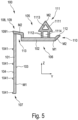
- the second profile leg 102 has a form-locking element 111 (see Fig. 5 ).
- the form-locking element 111 projects upwards along the vertical axis Z from the top side 105 of the second profile leg 102.
- the form-locking element 111 is designed for a form-locking connection with a frame groove 406 of the window frame 400.
- the frame groove 406 is along the vertical axis Z from below countersunk upwards into the underside 405 of the window frame 400, in particular the frame profile 402 of the window frame 400.
- the frame groove 405 extends over the entire length of the window frame 400.
- the form-fitting element 111 engages in the frame groove 406 in a form-fitting manner.
- the form-fitting effect acts downwards along the vertical axis Z and forwards and backwards along the transverse axis Y.
- the form-fitting element 111 has a head portion 1111 and two strut portions 1112.
- the head section 1111 is connected to the other sections of the second profile leg 102 by means of the two strut sections 1112.
- the head section 1111 has a cross-section, ie in a YZ plane (see Fig. 5 ), has a triangular shape.
- the two lower corners of the triangular shape (without reference symbol) form undercuts which engage in the frame groove 406 in a form-fitting manner downwards along the vertical axis Z.
- the head section 1111 has a hollow chamber 1113 which is also triangular in shape and is longitudinally extended over the entire length of the form-fitting element 111.
- the two strut sections 1112 are spaced apart from one another along the transverse axis Y.
- a further hollow chamber 1114 is arranged between the two strut sections 1112, which has an approximately square cross-sectional shape.
- the further hollow chamber 114 is also longitudinally extended over the entire length of the form-fitting element 111.
- the form-locking element 1111 is longitudinally extended over an entire length of the second profile leg 102 and thus also over an entire length of the sealing profile 100.
- the upper side 105 of the second profile leg 102 also has a sealing lip 112.
- the sealing lip 112 is elongated along the longitudinal axis X and is designed to form a sealing contact with the underside 405 of the window frame 400.
- the sealing lip 112 lies tightly against the underside 405 of the window frame (see Fig. 4 ).
- the sealing lip 112 is longitudinally extended over the entire length of the second profile leg 102 and thus also of the sealing profile 100.
- the sealing lip 112 forms the said front end 110 of the second profile leg 102.
- the underside 106 of the second profile leg 102 has a receiving groove 113.
- the receiving groove 113 is longitudinally extended along the longitudinal axis X and is sunk upwards into the underside 106 of the second profile leg 102 with respect to the vertical axis Z.
- the receiving groove 113 is plugged together with the window sill flange 301, more precisely: its upper end 3011.
- the upper end 3011 is tightly received in the receiving groove 113.
- the upper end 3011 lies tightly against the receiving groove 113 on both sides with respect to the transverse axis Y.
- the receiving groove 113 forms the said rear end 109 of the second profile leg 102.
- the receiving groove 113 is arranged in the region of the upper end 108 of the first profile leg 101.
- the form-locking element 111 is arranged in the present case with respect to the transverse axis Y between the sealing lip 112 and the receiving groove 113. Starting from an imaginary center of the second profile leg 102, the form-locking element 111 is arranged along the transverse axis Y in the direction of the sealing lip 112 and thus offset to the front.
- the rear sealing surface 104 of the first profile leg 101 has a plurality of projections 1041 positioned at a distance from one another along the vertical axis Z.
- the projections 1041 serve to improve sealing against the frame flange 401.
- the projections 1041 can each also be referred to as a sealing lip.
- the rear end 109 - and thus also the upper end 108 - has a rear sealing lip 1091.
- the rear sealing lip 1091 rests against the frame flange 401 when the sealing profile 100 is in the assembled state.
- the rear sealing lip 1091 projects slightly backwards along the transverse axis Y over the rear sealing surface 104 of the first profile leg 101.
- both the projections 1041 and the rear sealing lip 1091 are longitudinally extended over the entire length of the sealing profile 100.
- the sealing profile 100 is made of different elastomeric plastics M1, M2, namely a first elastomeric plastic M1 and a second elastomeric plastic M2.
- production takes place by means of coextrusion.
- the first elastomeric plastic M1 has a first hardness.
- the second elastomeric plastic M2 has a comparatively lower second hardness.
- the first hardness is 60 Shore and the second hardness is 40 Shore.
- the comparatively less hard elastomeric second plastic M2 is used in the present case to form the Receiving groove 113, the form-locking element 111 and the sealing lip 112.
- the comparatively harder first elastomeric plastic M1 forms the remaining sections of the sealing profile 100.
- the sealing element 200 of the sealing arrangement 1 is in the assembled state in a corner area E (see Fig. 1 , 6 , 7 ) between the window frame 400, the window sill 300 and the reveal 600.
- the sealing element 200 serves to provide a watertight seal for the so-called trade hole. If the trade hole is not sealed or is not sealed properly, water can enter the building. The sealing element 200 primarily counteracts such water ingress via the trade hole.
- sealing arrangement 1 preferably has two sealing elements 200, which are each arranged at corner regions opposite one another along the longitudinal axis X. In the figures, only one sealing element 200 is shown here.
- the sealing element 200 has a cap portion 201 and a foot portion 202 (see Fig. 7 to 10 ).
- the foot section 202 has an inner side 203 located in relation to the longitudinal axis X and an outer side 204.
- the outer side 204 lies opposite the inner side 203 along the longitudinal axis X.
- the foot section 202 is arranged between the reveal 600 and an outer side 501 of the sliding closure 500 with respect to the longitudinal axis X.
- the outer side 204 faces the reveal 600.
- the inner side 203 faces the outer side 501 of the sliding closure 500.
- the cap section 201 protrudes inward from the inner side 203 of the foot section 202 along the longitudinal axis X.
- the cap section 201 has an upper sealing surface 205 and a lower sealing surface 206 with respect to the vertical axis Z.
- the lower sealing surface 206 lies opposite the upper sealing surface 205 along the vertical axis Z.
- Fig. 4 shows that the sealing element 200 is slightly wider than the sealing profile 100 in relation to the transverse axis Y. It is also understood that the sealing element 200 is significantly shorter than the sealing profile 100 in relation to the longitudinal axis X. The length of the sealing element 200 corresponds approximately to a width of the sliding closure 500 in relation to the longitudinal axis X. Further details of the sealing element 200 are given in the Fig. 8 to 10 shown.
- the foot section 202 has a rectangular basic shape in the present case.
- a thickness of the foot section 202 related to the longitudinal axis X is significantly smaller than its extension along the vertical axis Z and along the transverse axis Y. This results in a disc-shaped or plate-shaped shape of the foot section 202 in the present case.
- the foot section 202 extends along the vertical axis Z between a lower end 208 and an upper end 209.
- the cap section 201 is arranged approximately centrally between the lower end 208 and the upper end 209 with respect to the vertical axis Z.
- the foot section 202 is oriented vertically in the assembled state.
- the cap section 201 is oriented horizontally.
- the cap portion 201 is approximately cuboid-shaped and extends with respect to the longitudinal axis X between an outer end 210 and an inner end 211.
- the inner end 211 is positioned on the inner side 203 of the foot portion 202.
- the lower sealing surface 206 of the cap section 201 has a projection 207.
- the projection 207 projects downwards from the lower sealing surface 206 along the vertical axis Z and is designed to engage over an inner end 5021 of the upper side 502 of the sliding closure 500 with respect to the longitudinal axis X (see Fig. 6 ).
- the projection 207 projects beyond the said front end 5021 inwards and downwards.
- the projection 207 is arranged on the inner end 211 of the cap section 201.
- the lower sealing surface 206 of the cap section 201 is inclined forwards with respect to the transverse axis Y.
- the inclination is 5° in this case.
- the inclination of the lower sealing surface 206 thus corresponds to a usual installation gradient of the window sill 300 and thus also of the sliding closure 500.
- the upper sealing surface 205 is aligned parallel to a horizontal plane in the assembled state of the sealing element 200.
- the window frame 400, the window sill 300, the sliding closure 500, the reveal 600 and the sealing arrangement 10 form a component arrangement 10.
- sealing element 200a which can be used as an alternative to the sealing element 200 as shown in the previous figures.
- the sealing element 200a is fundamentally very similar to the sealing element 200, so that in order to avoid repetition, the main differences between the sealing element 200a and the sealing element 200 are discussed below.
- Components and/or sections of the sealing element 200a with the same function are identified with identical reference numerals with the addition of the lower case letter "a".
- the sealing element 200a in turn has a cap section 201a and a foot section 202a.
- the foot section 202a has an inner side 203a located inward with respect to the longitudinal axis X and an outer side 204a.
- the cap section 201a protrudes inward along the longitudinal axis X from the inner side 203a of the foot section 202a.
- the cap section 201a has an upper sealing surface 205a and a lower sealing surface 206a.
- the orientation and function of said sections and surfaces is analogous to what has already been disclosed for the sealing element 200.
- the sealing element 200a is designed as an end cap K.
- the end cap K can be attached axially along the transverse axis Y and thus in the axial direction of the sliding closure 500 onto the rear end 503 thereof.
- the attachment direction is in Fig. 11 marked with an arrow.
- the end cap K is already attached to the rear end 503 of the sliding closure 500 during production.
- the sliding closure 500 is therefore already present with the end cap K attached. This avoids processing errors by the end user, which ultimately contributes to improved sealing of the corner area E.
- the end cap K has a bottom portion 211a and a rear wall portion 212a.
- the bottom section 211a is opposite the cap section 201a with respect to the vertical axis Z.
- the end cap K is fixed along the vertical axis Z by means of the cap portion 201a and the base portion 211a are held in a form-fitting manner at the rear end 503.
- the base section 211a has a wraparound portion 2011a which is designed to be pushed axially onto a profile leg of the sliding closure 500.
- the wraparound portion 2011a has a U-shape in cross-section, wherein the said profile leg of the sliding closure 500 is arranged and held in the pushed-on state between the opposite legs of the U-shape of the wraparound portion 2011a.
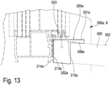
- the rear wall section 212a When plugged in, the rear wall section 212a lies along the transverse axis Y - and thus in the longitudinal direction of the sliding closure 500 - between the first profile leg 101 of the sealing profile 100 and the rear end 503 of the sliding closure 500 (see Fig. 13 ).
- An outer side 214a of the rear wall section 212a rests against the front sealing surface 103 of the first profile leg 101 of the sealing profile 100.
- the inner side 213a (in Fig. 13 shown in dashed lines) rests in a rear end of the sliding closure 500.
- the upper sealing surface 205a of the cap portion 201a rests against the underside 106 of the second profile leg 102a.
- the end cap K may have a support part 215a which is Fig. 13 is indicated by dashed lines.
- the support part 215a can be formed, for example, by a compressible material that can be glued onto the cap section 201a.
- the upper sealing surface 205a is a surface of the support part 215a.
Landscapes
- Engineering & Computer Science (AREA)
- Civil Engineering (AREA)
- Structural Engineering (AREA)
- Specific Sealing Or Ventilating Devices For Doors And Windows (AREA)
Abstract
Description
- Die Erfindung betrifft ein Dichtungsprofil zum wasserdichten Abdichten eines Anschlussbereichs zwischen einer Fensterbank und einem Fensterrahmen.
- Fensterbänke auf der Fassadenaußenseite dienen neben der optischen Gestaltung primär dem Witterungsschutz. Um Niederschläge kontrolliert von der Fassade abzuleiten und einen Wassereintritt in den Baukörper zu vermeiden, muss die Fensterbank an benachbarte Bauelemente, wie den Fensterrahmen oder die Laibung, fachgerecht angeschlossen werden.
- Zum Anschluss an den Fensterrahmen weisen Fensterbänke üblicherweise einen Fensterbankflansch auf, der auch als Aufkantung bezeichnet wird und zum Verschrauben mit einem Rahmenflansch des Fensterrahmens vorgesehen ist. Der Rahmenflansch ist oftmals an einem Fensterbankanschlussprofil des Fensterrahmens angeordnet, das auch als Anschraub- oder Basisprofil bezeichnet werden kann. Das Fensterbankanschlussprofil bildet eine untere Aufdoppelung des eigentlichen Rahmenprofils des Fensterrahmens.
- Zum wasserdichten Abdichten des Anschlusses sind aus dem Stand der Technik vorkomprimierte Dichtbänder bekannt, die zwischen dem Fensterbankflansch und dem Rahmenflansch angeordnet werden.
- Aufgabe der Erfindung ist es, ein Dichtungsprofil der eingangs genannten Art bereitzustellen, das eine verbesserte Abdichtung des Anschlussbereichs zwischen der Fensterbank und dem Fensterrahmen ermöglicht.
- Diese Aufgabe wird durch das Bereitstellen eines Dichtungsprofils mit den Merkmalen des Anspruchs 1 gelöst.
- Das erfindungsgemäße Dichtungsprofil ist zum wasserdichten Abdichten eines Anschlussbereichs zwischen einer Fensterbank mit einem Fensterbankflansch und einem Fensterrahmen mit einem Rahmenflansch vorgesehen. Das Dichtungsprofil ist entlang einer Längsachse längserstreckt und weist einen ersten Profilschenkel und einen zweiten Profilschenkel auf. Der erste Profilschenkel ist zur Anordnung zwischen dem Fensterbankflansch und dem Rahmenflansch eingerichtet und weist eine in Bezug auf eine Querachse vordere Dichtfläche sowie eine der vorderen Dichtfläche gegenüberliegende hintere Dichtfläche auf. Die vordere Dichtfläche ist zum Ausbilden eines Dichtkontakts mit dem Fensterbankflansch eingerichtet. Die hintere Dichtfläche ist zum Ausbilden eines Dichtkontakts mit dem Rahmenflansch eingerichtet. Der zweite Profilschenkel ragt entlang der Querachse nach vorne von dem ersten Profilschenkel ab und weist eine in Bezug auf eine Hochachse obenliegende Oberseite sowie eine der Oberseite gegenüberliegende Unterseite auf. Die Oberseite des zweiten Profilschenkels ist zum Ausbilden eines Dichtkontakts mit einer Unterseite des Fensterrahmens eingerichtet. Die Unterseite des zweiten Profilschenkels ist zum Ausbilden eines Dichtkontakts mit einem oberen Ende des Fensterbankflanschs eingerichtet. Durch die erfindungsgemäße Lösung wird eine verbesserte Abdichtung des Anschlussbereichs erreicht. Zu diesem Zweck ist das Dichtungsprofil zum Ausbilden mehrerer Dichtkontakte mit unterschiedlichen Stellen des Anschlussbereichs eingerichtet. Der erste Profilschenkel dient einer unmittelbaren Abdichtung der Verbindung zwischen dem Fensterbankflansch und dem Rahmenflansch. Der mit dem ersten Profilschenkel verbundene zweite Profilschenkel dient einer zusätzlichen Abdichtung im Bereich der Unterseite des Fensterrahmens und im Bereich des oberen Endes des Fensterbankflanschs. Dabei dient die Oberseite des zweiten Profilschenkels zur Abdichtung gegen die Unterseite des Fensterrahmens. Die Unterseite des zweiten Profilschenkels dichtet gegen das obere Ende des Fensterbankflanschs ab. Durch diese beiden Dichtkontakte des zweiten Profilschenkels wird einem Wassereintritt über die Unterseite des Fensterrahmens und/oder das obere Ende des Fensterbankflanschs entgegengewirkt. Der erste Profilschenkel weist die vordere Dichtfläche und die hintere Dichtfläche zur Ausbildung des jeweiligen Dichtkontakts auf. Der zweite Profilschenkel ist bei unterschiedlichen Ausgestaltungen auf unterschiedliche Weise zum Ausbilden der jeweiligen Dichtkontakte mit dem oberen Ende des Fensterbankflanschs und der Unterseite des Fensterrahmens ausgebildet. Bei einer Ausgestaltung weist die Oberseite des zweiten Profilschenkels zu diesem Zweck wenigstens eine Dichtfläche auf. Bei einer weiteren Ausgestaltung ist alternativ oder zusätzlich wenigstens eine Dichtlippe vorhanden. Entsprechendes gilt, mutatis mutandis, für die Unterseite des zweiten Profilschenkels. Vorzugsweise ist das Dichtungsprofil aus einem elastischen Werkstoff gefertigt, insbesondere einem elastomeren Kunststoff. Bei der abzudichtenden Fensterbank handelt es sich um eine Fensterbank für eine Fassadenaußenseite, d.h. eine Außenfensterbank. Die abzudichtende Fensterbank ist vorzugsweise aus Metall gefertigt, insbesondere aus Aluminium. Die Längsachse, die Querachse und die Hochachse des Dichtungsprofils bilden ein orthogonales Achsensystem. Die in dieser Beschreibung verwendeten Richtungs- und Lagebezeichnungen beziehen sich auf eine übliche Einbaulage der Fensterbank und damit auch des Dichtungsprofils. In dieser üblichen Einbaulage sind die Längsachse und die Querachse in einer Horizontalebene erstreckt und die Hochachse ist in einer Vertikalebene erstreckt. Die Längsachse ist dabei parallel zu einer Längsachse der Fensterbank und damit einer Breite des betreffenden Fensters ausgerichtet. Die Querachse ist in Tiefenrichtung der Fensterbank ausgerichtet. In Bezug auf die Querachse nach vorne meint nach außen oder in Richtung der Fassadenaußenseite. In Bezug auf die Querachse nach hinten meint in Richtung des Inneren des Baukörpers. In Bezug auf die Längsachse nach außen meint der betreffenden Laibung zugewandt und nach innen meint von der Laibung abgewandt.
- In Ausgestaltung der Erfindung weist die Oberseite des zweiten Profilschenkels ein Formschlusselement auf, das entlang der Längsachse längserstreckt ist und in Bezug auf die Hochachse nach oben aufragt, und das zur formschlüssigen Verbindung mit einer in die Unterseite des Fensterrahmens eingesenkten Rahmennut eingerichtet ist. Das Formschlusselement dient einer formschlüssigen Verbindung mit der Rahmennut des Fensterrahmens. Durch die formschlüssige Verbindbarkeit des Dichtungsprofils mit dem Fensterrahmen kann eine vereinfachte Montage des Dichtungsprofils erreicht werden. Die besagte Rahmennut ist bei üblichen Fensterrahmen in die Unterseite des Fensterrahmens, im Speziellen des Rahmenprofils, eingesenkt. Die Rahmennut ist vorzugsweise über eine gesamte entlang der Längsachse verlaufende Länge des Fensterrahmens erstreckt. Vorzugsweise ist das Formschlusselement über eine gesamte Länge des zweiten Profilschenkels und/oder des Dichtungsprofils längserstreckt. Um eine zuverlässige formschlüssige Verbindung zu erreichen, ist die Gestaltung des Formschlusselements auf die Form und/oder Abmessungen der Rahmennut abgestimmt. Zur formschlüssigen Verbindung kann das Formschlusselement entlang der Hochachse von unten nach oben in die Rahmennut gedrückt, eingesteckt und/oder eingerastet werden. Bei einer alternativen Ausgestaltung ist anstelle des Formschlusselements ein doppelseitiges Klebeband vorgesehen, das auf die Oberseite des zweiten Profilschenkels aufgeklebt ist. Zur Verbindung des Dichtungsprofils mit dem Fensterrahmen kann das doppelseitige Klebeband auf dessen Unterseite geklebt werden. Die zum Verkleben mit dem Fensterrahmen vorgesehene Seite des doppelseitigen Klebebands kann mit einer abziehbaren Schutzfolie abgedeckt sein.
- In weiterer Ausgestaltung der Erfindung weist die Oberseite des zweiten Profilschenkels eine Dichtlippe auf, die entlang der Längsachse längserstreckt ist, und die zum Ausbilden des Dichtkontakts mit der Unterseite des Fensterrahmens eingerichtet ist. Die Dichtlippe erlaubt eine zuverlässige Abdichtung gegen die Unterseite des Fensterrahmens. Vorzugsweise ist die Dichtlippe über eine gesamte Länge des zweiten Profilschenkels und/oder des Dichtungsprofils längserstreckt. Sofern der abzudichtende Fensterrahmen eine in seine Unterseite eingesenkte Rahmennut aufweist, kontaktiert die Dichtlippe die Unterseite des Fensterrahmens vorzugsweise entlang der Querachse vor der Rahmennut. Sofern der zweite Profilschenkel ein Formschlusselement aufweist, ist die Dichtlippe vorzugsweise entlang der Querachse vor dem Formschlusselement positioniert.
- In weiterer Ausgestaltung der Erfindung bildet die Dichtlippe ein in Bezug auf die Querachse vorderes Ende des zweiten Profilschenkels. Hierdurch wird der zweite Profilschenkel und damit das Dichtungsprofil auf einfache und wirkungsvolle Weise gegen einen Wassereintritt über das vordere Ende des zweiten Profilschenkels abgedichtet.
- In weiterer Ausgestaltung der Erfindung weist die Unterseite des zweiten Profilschenkels eine Aufnahmenut auf, die entlang der Längsachse längserstreckt und in Bezug auf die Hochachse nach oben in die Unterseite des zweiten Profilschenkels eingesenkt ist, und die zur dichtenden Aufnahme des oberen Endes des Fensterbankflanschs eingerichtet ist. In montiertem Zustand des Dichtungsprofils sind die Aufnahmenut und das obere Ende des Fensterbankflanschs zusammengesteckt. In eingestecktem Zustand ist das obere Ende des Fensterbankflanschs dicht in der Aufnahmenut aufgenommen. Hierdurch wird ein Wassereintritt über das obere Ende des Fensterbankflanschs auf einfache und wirkungsvolle Weise vermieden. Zudem wird hierdurch die Montage des Dichtungsprofils vereinfacht. Die Aufnahmenut ist vorzugsweise über eine gesamte Länge des zweiten Profilschenkels und/oder des Dichtungsprofils längserstreckt.
- In weiterer Ausgestaltung der Erfindung bildet die Aufnahmenut ein in Bezug auf die Querachse hinteres Ende des zweiten Profilschenkels. Hierdurch wird ein vereinfachter Aufbau des Dichtungsprofils erreicht.
- In weiterer Ausgestaltung der Erfindung ist das Dichtungsprofil aus wenigstens einem elastomeren Kunststoff extrudiert. Dabei kommt grundsätzlich jeder für die vorliegende Verwendung als Dichtungsprofil geeignete elastomere Kunststoff infrage. Solche Kunststoffe sind dem Fachmann bekannt. Als besonders vorteilhaft hat sich Ethylen-Propylen-Dien-Kautschuk (EPDM) erwiesen.
- In weiterer Ausgestaltung der Erfindung ist das Dichtungsprofil aus einem ersten elastomeren Kunststoff mit einer ersten Härte und einem zweiten elastomeren Kunststoff mit einer geringeren zweiten Härte koextrudiert, insbesondere wobei der zweite elastomere Kunststoff das Formschlusselement und/oder die Dichtlippe und/oder die Aufnahmenut bildet. Durch die Koextrusion aus unterschiedlich harten elastomeren Kunststoffen kann das Dichtungsprofil hinsichtlich seiner Eigenschaften bereichsweise an die in dem jeweiligen Bereich im Vordergrund stehende Funktion angepasst werden. Vorzugsweise wird der elastomere Kunststoff mit geringerer Härte zum Extrudieren des Formschlusselements und/oder der Dichtlippe und/oder der Aufnahmenut verwendet. Hierdurch können die besagten Funktionselemente und/oder Abschnitte vergleichsweise nachgiebiger ausgebildet werden. Dies kommt der Dichtfunktion zugute. Vorzugsweise handelt es sich bei dem ersten elastomeren Kunststoff und dem zweiten elastomeren Kunststoff jeweils um einen Ethylen-Propylen-Dien-Kautschuk. Vorzugsweise beträgt die erste Härte von 50 bis 70 Shore, bevorzugt 60 Shore. Weiter vorzugsweise beträgt die zweite Härte von 30 bis 50 Shore, bevorzugt 40 Shore.
- Die Erfindung betrifft zudem eine Dichtungsanordnung mit einem Dichtungsprofil gemäß der vorhergehenden Beschreibung und mit wenigstens einem Dichtelement. Das Dichtelement der erfindungsgemäßen Dichtungsanordnung ist zur Anordnung in einem Eckbereich zwischen dem Fensterrahmen, der Fensterbank und einer Laibung eingerichtet. Das erfindungsgemäße Dichtelement weist einen Kappenabschnitt und einen Fußabschnitt auf. Der Fußabschnitt weist eine in Bezug auf die Längsachse innenliegende Innenseite und eine der Innenseite gegenüberliegende Außenseite auf. Die Innenseite des Fußabschnitts ist zur Anlage an einer Außenseite eines Gleitabschlusses eingerichtet, der zwischen dem Stirnende der Fensterbank und der Laibung angeordnet ist. Die Außenseite des Fußabschnitts ist zur Anlage an der Laibung eingerichtet. Der Kappenabschnitt ragt entlang der Längsachse nach innen von der Innenseite des Fußabschnitts ab und weist eine in Bezug auf die Hochachse obere Dichtfläche und eine der oberen Dichtfläche gegenüberliegende untere Dichtfläche auf. Die obere Dichtfläche ist zum Ausbilden eines Dichtkontakts mit der Unterseite des zweiten Profilschenkels eingerichtet. Die untere Dichtfläche ist zum Ausbilden eines Dichtkontakts mit einer Oberseite des Gleitabschlusses eingerichtet. Das Dichtelement der erfindungsgemäßen Dichtungsanordnung erlaubt eine verbesserte Abdichtung des besagten Eckbereichs zwischen dem Fensterrahmen, der Fensterbank und der Laibung. In diesem Eckbereich ist üblicherweise ein sogenanntes Gewerkeloch vorhanden. Werden keine besonderen Vorkehrungen getroffen, kann Niederschlag über das Gewerkeloch in den Baukörper eintreten. Das Dichtelement der erfindungsgemäßen Dichtungsanordnung erlaubt eine unaufwändige und zuverlässige Abdichtung des Gewerkelochs. In montiertem Zustand ist der Fußabschnitt des Dichtelements in Bezug auf die Längsachse zwischen der Außenseite des Gleitabschlusses und der Laibung angeordnet. Bei dem Gleitabschluss handelt es sich um ein dem Fachmann bekanntes Bauelement zum Ausgleich von wärmebedingten Längenänderungen der Fensterbank in Relation zu der Laibung. Der Kappenabschnitt des Dichtelements ist in montiertem Zustand in Bezug auf die Hochachse zwischen der Oberseite des Gleitabschlusses und der Unterseite des zweiten Profilschenkels und damit auch der Unterseite des Fensterrahmens angeordnet. Dabei bildet die obere Dichtfläche des Kappenabschnitts einen Dichtkontakt mit der Unterseite des zweiten Profilschenkels. Die untere Dichtfläche des Kappenabschnitts bildet einen Dichtkontakt mit der Oberseite des besagten Gleitabschlusses. Vorzugsweise ist das Dichtelement aus einem elastischen Werkstoff gefertigt, beispielsweise einem elastomeren Kunststoff. Vorzugsweise weist die Dichtungsanordnung das Dichtelement und ein weiteres Dichtelement auf. Dabei ist das weitere Dichtelement zur Anordnung in einem dem Eckbereich entlang der Längsachse gegenüberliegenden weiteren Eckbereich zwischen dem Fensterrahmen, der Fensterbank und der gegenüberliegenden Seite der Laibung eingerichtet.
- In weiterer Ausgestaltung der Erfindung weist die untere Dichtfläche des Kappenabschnitts einen in Bezug auf die Hochachse nach unten abragenden Vorsprung auf, der zum Übergreifen eines in Bezug auf die Längsachse innenliegenden Stirnendes der Oberseite des Gleitabschlusses eingerichtet ist. Der Vorsprung erlaubt zum einen eine vereinfachte Positionierung des Dichtelements bei der Montage. Zum anderen erlaubt der Vorsprung eine verbesserte Abdichtung gegen die Oberseite des Gleitabschlusses.
- In weiterer Ausgestaltung der Erfindung ist die untere Dichtfläche des Kappenabschnitts in Bezug auf die Querachse nach vorne geneigt, wobei die Neigung zwischen 2° und 10°, bevorzugt zwischen 4° und 8°, besonders bevorzugt 5°, beträgt. Bei fachgerechter Montage werden Fensterbänke üblicherweise mit einem Gefälle in Richtung der Fassadenaußenseite eingebaut, so dass Niederschläge nach vorne von der Fensterbank ablaufen können. Dementsprechend weist auch der an dem Stirnende der Fensterbank angebrachte Gleitabschluss ein entsprechendes Gefälle auf. Die Neigung der unteren Dichtfläche des Kappenabschnitts entspricht folglich dem Einbaugefälle der Fensterbank/des Gleitabschlusses. Hierdurch wird eine möglichst vollflächige Ausbildung des Dichtkontakts zwischen der unteren Dichtfläche und der Oberseite des Gleitabschlusses gewährleistet.
- In weiterer Ausgestaltung der Erfindung ist das Dichtelement als Endkappe gestaltet und zum axialen Aufstecken auf ein hinteres Ende des Gleitabschlusses eingerichtet. Im Vergleich zu dem Dichtelement gemäß den vorhergehenden Ausgestaltungen erlaubt die Endkappe eine vereinfachte Montage der Dichtungsanordnung durch den Endanwender. Insbesondere werden Verarbeitungsfehler vermieden. Die besagten Vorteile ergeben sich aus der axialen Aufsteckbarkeit der Endkappe. Vorzugsweise wird die Endkappe bereits fertigungsseitig auf das hintere Ende des Gleitabschlusses aufgesteckt. Vorzugsweise ist die Endkappe derart gestaltet, dass sich im aufgesteckten Zustand ein Formschluss mit dem hinteren Ende des Gleitabschlusses ergibt.
- In weiterer Ausgestaltung der Erfindung weist die Endkappe einen Bodenabschnitt auf, der dem Kappenabschnitt in Bezug auf die Hochachse gegenüberliegt und einen Umgriff aufweist, der zum axialen Aufschieben auf einen Profilschenkel des Gleitabschlusses eingerichtet ist. Der Bodenabschnitt und der Kappenabschnitt liegen einander entlang der Hochachse gegenüber, wobei der Bodenabschnitt im montierten Zustand der Dichtungsanordnung einer Brüstung der betreffenden Fensteröffnung zugewandt und damit der Fensterbank abgewandt ist. Das hintere Ende des Gleitabschlusses liegt in Bezug auf die Hochachse zwischen dem Kappenabschnitt und dem Bodenabschnitt der Endkappe. Der Umgriff des Bodenabschnitts ist zum axialen Aufschieben auf den besagten Profilschenkel des Gleitabschlusses eingerichtet. Vorzugsweise ist der Umgriff im Querschnitt U-förmig gestaltet.
- In weiterer Ausgestaltung der Erfindung weist die Endkappe einen Rückwandabschnitt mit einer Innenseite und einer axial gegenüberliegenden Außenseite auf, wobei die Innenseite in aufgestecktem Zustand an einem hinteren Stirnende des Gleitabschlusses und/oder dem Fensterbankflansch anliegt, und wobei die Außenseite des Rückwandabschnitts an der vorderen Dichtfläche des ersten Profilschenkels des Dichtungsprofils anliegt. Im montierten Zustand liegt der Rückwandabschnitt folglich in Längsrichtung des Gleitabschlusses - und damit entlang der Querachse - zwischen der vorderen Dichtfläche des ersten Profilschenkels des Dichtungsprofils und dem hinteren Stirnende des Gleitabschlusses. In weiterer Ausgestaltung der Erfindung ist das Dichtelement aus einem elastomeren Kunststoff gefertigt. Als besonders vorteilhaft hat sich Ethylen-Propylen-Dien-Kautschuk erwiesen.
- Die Erfindung betrifft zudem eine Bauelementeanordnung mit einem Fensterrahmen, einer Fensterbank, wenigstens einem Gleitabschluss, einer Laibung und mit einer Dichtungsanordnung gemäß der vorhergehenden Beschreibung.
- Weitere Vorteile und Merkmale der Erfindung ergeben sich aus den Ansprüchen sowie aus der nachfolgenden Beschreibung bevorzugter Ausführungsbeispiele der Erfindung, die anhand der Zeichnungen dargestellt sind.
- Fig. 1
- zeigt in schematischer Frontansicht einen Bereich einer Gebäudefassade mit einem in eine Fensteröffnung eingesetzten Fenster samt Fensterbank,
- Fig. 2
- eine schematische Schnittansicht des Fassadenbereichs entlang einer Schnittlinie A-A nach
Fig. 1 , - Fig. 3
- einen vergrößerten Teilbereich B der Schnittansicht nach
Fig. 2 , - Fig. 4
- eine nochmals vergrößerte Detailansicht der Schnittansicht nach
Fig. 3 im Bereich einer Dichtungsanordnung zum Abdichten eines Anschlussbereichs zwischen der Fensterbank und dem Fensterrahmen des Fensters, - Fig. 5
- ein Dichtungsprofil der Dichtungsanordnung nach
Fig. 4 in einer Schnittdarstellung, - Fig. 6
- eine perspektivische Explosionsansicht der Dichtungsanordnung in einem Eckbereich zwischen dem Fensterrahmen, der Fensterbank und der Laibung der Fensteröffnung,
- Fig. 7
- einen Bereich E der schematischen Frontansicht nach
Fig. 1 in vergrößerter Detaildarstellung, - Fig. 8, 9, 10
- eine erste Ausführungsform eines Dichtelements der Dichtungsanordnung in unterschiedlichen Ansichten,
- Fig. 11
- eine zweite Ausführungsform eines Dichtelements der Dichtungsanordnung zusammen mit einem Gleitabschluss und der Fensterbank, wobei das Dichtelement als Endkappe gestaltet ist,
- Fig. 12
- eine vergrößerte Perspektivansicht der Endkappe nach
Fig. 11 und - Fig. 13
- eine vergrößerte Detailansicht des Eckbereichs mit Blickrichtung auf eine Außenseite des Endkappe nach den
Figuren 11 und 12 . - Gemäß den
Fig. 1 bis 4 ist ein Fensterrahmen 400 in eine Laibung 600 einer Gebäudefassade (ohne Bezugszeichen) eingesetzt. Der Fensterrahmen 400 ist auf ein dem Fachmann bekannte Weise fest mit der Laibung 600 verbunden und trägt einen schwenkbeweglichen Fensterflügel F, in welchen eine Fensterscheibe S eingesetzt ist. An den Fensterrahmen 400 ist eine Fensterbank 300 angeschlossen. Die Fensterbank 300, genauer: Außenfensterbank, ist entlang einer Längsachse X längserstreckt und an ihren gegenüberliegenden Stirnenden mittels jeweils eines Gleitabschlusses 500 an die Laibung 600 angeschlossen. Die Gleitabschlüsse 500 dienen dem Ausgleich von Längenänderungen und weisen eine dem Fachmann bekannte Gestaltung und Funktion auf. - Zum wasserdichten Abdichten des Anschlussbereichs zwischen der Fensterbank 300 und dem Fensterrahmen 400 ist ein Dichtungsprofil 100 vorhanden (siehe
Fig. 4 ,5 ). Das Dichtungsprofil 100 ist Bestandteil einer Dichtungsanordnung 1. Die Dichtungsanordnung 1 weist das besagte Dichtungsprofil 100 und wenigstens ein Dichtelement 200 auf (sieheFig. 4 ,6 bis 10 ). - Das Dichtungsprofil 100 ist entlang einer Längsachse X längserstreckt. Die Längsachse X ist in montiertem Zustand des Dichtungsprofils 100 parallel zur Längserstreckung der Fensterbank 300. Das Dichtungsprofil 100 weist einen ersten Profilschenkel 101 und einen zweiten Profilschenkel 102 auf.
- Der erste Profilschenkel 101 ist in montiertem Zustand zwischen einem Fensterbankflansch 301 der Fensterbank 300 und einem Rahmenflansch 401 des Fensterrahmens 400 angeordnet (siehe
Fig. 4 ). - Der Fensterbankflansch 301 ist an einem in Bezug auf eine Querachse Y hinteren Ende der Fensterbank 300 angeordnet und wird auch als Aufkantung bezeichnet. Der Rahmenflansch 401 dient der Befestigung des Fensterbankflanschs 301, wobei vorliegend eine in den Figuren nicht näher gezeigte Befestigung mittels Schrauben vorgesehen ist. Der Fensterbankflansch 301 und der Rahmenflansch 401 sind auf übliche Weise über eine gesamte entlang der Längsachse X erstreckte Länge der Fensterbank 300 bzw. des Fensterrahmens 400 längserstreckt.
- Bei der gezeigten Ausführungsform ist der Rahmenflansch 401 an einem Fensterbankanschlussprofil 403 des Fensterrahmens 400 angeordnet. Das Fensterbankanschlussprofil 403 ist auf nicht näher gezeigte Weise mit einem (eigentlichen) Rahmenprofil 402 des Fensterrahmens 400 verbunden. Beispielsweise kann das Fensterbankanschlussprofil 403 mit dem Rahmenprofil 402 verschraubt oder verrastet sein.
- Der erste Profilschenkel 101 weist eine in Bezug auf die Querachse Y vordere Dichtfläche 103 und eine hintere Dichtfläche 104 auf. Die hintere Dichtfläche 104 liegt der vorderen Dichtfläche 103 in Bezug auf die Querachse Y gegenüber. In montiertem Zustand bildet die vordere Dichtfläche 103 einen Dichtkontakt mit dem Fensterbankflansch 301 aus. Die hintere Dichtfläche 104 bildet einen Dichtkontakt mit dem Rahmenflansch 401 aus.
- Der zweite Profilschenkel 102 ragt entlang der Querachse Y nach vorne von dem ersten Profilschenkel 101 ab und weist eine in Bezug auf eine Hochachse Z obenliegende Oberseite 105 und eine Unterseite 106 auf. Die Unterseite 106 liegt der Oberseite 105 in Bezug auf die Hochachse Z gegenüber. Die Oberseite 105 des zweiten Profilschenkels 102 dient einer Abdichtung gegen eine Unterseite 405 des Fensterrahmens 400. Die Unterseite 106 des zweiten Profilschenkels 102 dient einer Abdichtung gegen ein oberes Ende 3011 des Fensterbankflanschs 301.
- Die besagte Unterseite 405 des Fensterrahmens 400 ist vorliegend an dem (eigentlichen) Rahmenprofil 402 des Fensterrahmens 400 angeordnet. Die Unterseite 403 weist in Bezug auf die Hochachse Z nach unten. Die Unterseite 405 des Rahmenprofils 402 liegt vorliegend in Bezug auf die Hochachse Z oberhalb des Rahmenflanschs 401.
- Der erste Profilschenkel 101 und der zweite Profilschenkel 102 sind jeweils entlang der Längsachse X sowie parallel längserstreckt. Bei der gezeigten Ausführungsform ist der erste Profilschenkel 101 im Querschnitt (siehe
Fig. 4 ,5 ) entlang der Hochachse Z erstreckt und somit vertikal orientiert. Der zweite Profilschenkel 102 ist vorliegend im Querschnitt entlang der Querachse Y erstreckt und somit horizontal orientiert. - Der erste Profilschenkel 101 ist im Querschnitt zwischen einem in Bezug auf die Hochachse Z unteren Ende 107 und einem oberen Ende 108 längserstreckt. Der zweite Profilschenkel 102 ist im Querschnitt entlang der Querachse Y zwischen einem hinteren Ende 109 und einem vorderen Ende 110 längserstreckt.
- Vorliegend fallen das obere Ende 108 des ersten Profilschenkels 101 und das hintere Ende 109 des zweiten Profilschenkels 102 zusammen. Mit anderen Worten ragt der zweite Profilschenkel 102 von dem oberen Ende 108 des ersten Profilschenkels 101 ab. Im Ergebnis weist das Dichtungsprofil 100 bei der gezeigten Ausführungsform eine in etwa L-förmige Querschnittsform auf.
- Vorliegend ist der erste Profilschenkel 101 im Querschnitt flach ausgebildet und weist folglich eine Gurt- oder auch Bandform auf. Entsprechendes gilt sinngemäß für den zweiten Profilschenkel 102.
- Um eine einfache und zuverlässige Verbindung des Dichtungsprofils 100 mit dem Fensterrahmen 400 zu ermöglichen, weist der zweite Profilschenkel 102 ein Formschlusselement 111 auf (siehe
Fig. 5 ). Das Formschlusselement 111 ragt entlang der Hochachse Z nach oben von der Oberseite 105 des zweiten Profilschenkels 102 auf. Das Formschlusselement 111 ist zur formschlüssigen Verbindung mit einer Rahmennut 406 des Fensterrahmens 400 eingerichtet. Die Rahmennut 406 ist entlang der Hochachse Z von unten nach oben in die Unterseite 405 des Fensterrahmens 400, im Speziellen des Rahmenprofils 402 des Fensterrahmens 400, eingesenkt. Die Rahmennut 405 erstreckt sich vorliegend über eine gesamte Länge des Fensterrahmens 400. In montiertem Zustand des Dichtungsprofils 100 greift das Formschlusselement 111 formschlüssig in die Rahmennut 406 ein. Dabei wirkt der besagte Formschluss entlang der Hochachse Z nach unten und entlang der Querachse Y nach vorne und nach hinten. - Bei der gezeigten Ausführungsform weist das Formschlusselement 111 einen Kopfabschnitt 1111 und zwei Strebenabschnitte 1112 auf.
- Der Kopfabschnitt 1111 ist mittels der beiden Strebenabschnitte 1112 mit den übrigen Abschnitten des zweiten Profilschenkels 102 verbunden. Der Kopfabschnitt 1111 weist bei der gezeigten Ausführungsform im Querschnitt, d.h. in einer Y-Z-Ebene (siehe
Fig. 5 ), eine dreieckige Form auf. Die beiden unteren Ecken der Dreiecksform (ohne Bezugszeichen) bilden Hinterschnitte, die entlang der Hochachse Z nach unten formschlüssig in die Rahmennut 406 eingreifen. Weiter weist der Kopfabschnitt 1111 eine Hohlkammer 1113 auf, die ebenfalls dreiecksförmig gestaltet und über eine gesamte Länge des Formschlusselements 111 längserstreckt ist. - Die beiden Strebenabschnitte 1112 sind entlang der Querachse Y voneinander beabstandet. Zwischen den beiden Strebenabschnitten 1112 ist eine weitere Hohlkammer 1114 angeordnet, die eine in etwa quadratische Querschnittsform aufweist. Auch die weitere Hohlkammer 114 ist über die gesamte Länge des Formschlusselements 111 längserstreckt.
- Das Formschlusselement 1111 ist über eine gesamte Länge des zweiten Profilschenkels 102 und damit auch über eine gesamte Länge des Dichtungsprofils 100 längserstreckt.
- Bei der gezeigten Ausführungsform weist die Oberseite 105 des zweiten Profilschenkels 102 zudem eine Dichtlippe 112 auf. Die Dichtlippe 112 ist entlang der Längsachse X längserstreckt und ist zum Ausbilden eines/des Dichtkontakts mit der Unterseite 405 des Fensterrahmens 400 eingerichtet. In montiertem Zustand des Dichtungsprofils 100 liegt die Dichtlippe 112 dicht an der Unterseite 405 des Fensterrahmens an (siehe
Fig. 4 ). Vorliegend ist die Dichtlippe 112 über die gesamte Länge des zweiten Profilschenkels 102 und damit auch des Dichtungsprofils 100 längserstreckt. - Bei der gezeigten Ausführungsform bildet die Dichtlippe 112 das besagte vordere Ende 110 des zweiten Profilschenkels 102.
- Die Unterseite 106 des zweiten Profilschenkels 102 weist bei der gezeigten Ausführungsform eine Aufnahmenut 113 auf. Die Aufnahmenut 113 ist entlang der Längsachse X längserstreckt und in Bezug auf die Hochachse Z nach oben in die Unterseite 106 des zweiten Profilschenkels 102 eingesenkt. Die Aufnahmenut 113 ist in montiertem Zustand des Dichtungsprofils mit dem Fensterbankflansch 301, genauer: dessen oberem Ende 3011, zusammengesteckt. Dabei ist das obere Ende 3011 dicht in der Aufnahmenut 113 aufgenommen. Das obere Ende 3011 liegt hierbei in Bezug auf die Querachse Y beidseits dicht an der Aufnahmenut 113 an.
- Vorliegend bildet die Aufnahmenut 113 das besagte hintere Ende 109 des zweiten Profilschenkels 102. Mit anderen Worten ist die Aufnahmenut 113 im Bereich des oberen Endes 108 des ersten Profilschenkels 101 angeordnet.
- Das Formschlusselement 111 ist vorliegend in Bezug auf die Querachse Y zwischen der Dichtlippe 112 und der Aufnahmenut 113 angeordnet. Ausgehend von einer gedachten Mitte des zweiten Profilschenkels 102 ist das Formschlusselement 111 entlang der Querachse Y in Richtung der Dichtlippe 112 und damit nach vorne versetzt angeordnet.
- Bei der gezeigten Ausführungsform weist die hintere Dichtfläche 104 des ersten Profilschenkels 101 mehrere entlang der Hochachse Z voneinander beabstandet positionierte Vorsprünge 1041 auf. Die Vorsprünge 1041 dienen einer verbesserten Abdichtung gegen den Rahmenflansch 401. Die Vorsprünge 1041 können jeweils auch als Dichtlippe bezeichnet werden.
- Vorliegend weist das hintere Ende 109 - und damit auch das obere Ende 108 - eine hintere Dichtlippe 1091 auf. Die hintere Dichtlippe 1091 liegt in montiertem Zustand des Dichtungsprofils 100 an dem Rahmenflansch 401 an. Die hintere Dichtlippe 1091 ragt entlang der Querachse Y nach hinten geringfügig über die hintere Dichtfläche 104 des ersten Profilschenkels 101. Sowohl die Vorsprünge 1041 als auch die hintere Dichtlippe 1091 sind bei der gezeigten Ausführungsform über die gesamte Länge des Dichtungsprofils 100 längserstreckt.
- Das Dichtungsprofil 100 ist bei der gezeigten Ausführungsform aus unterschiedlichen elastomeren Kunststoffen M1, M2, nämlich einem ersten elastomeren Kunststoff M1 und einem zweiten elastomeren Kunststoff M2 gefertigt. Die Fertigung erfolgt vorliegend mittels Koextrusion. Dabei weist der erste elastomere Kunststoff M1 eine erste Härte auf. Der zweite elastomere Kunststoff M2 weist eine im Vergleich geringere zweite Härte auf. Bei der gezeigten Ausführungsform beträgt die erste Härte 60 Shore und die zweite Härte beträgt 40 Shore. Der im Vergleich weniger harte elastomere zweite Kunststoff M2 ist vorliegend zum Ausbilden der Aufnahmenut 113, des Formschlusselements 111 und der Dichtlippe 112 vorgesehen. Der im Vergleich härtere erste elastomere Kunststoff M1 bildet die übrigen Abschnitte des Dichtungsprofils 100 aus.
- Das Dichtelement 200 der Dichtungsanordnung 1 ist in montiertem Zustand in einem Eckbereich E (siehe
Fig. 1 ,6 ,7 ) zwischen dem Fensterrahmen 400, der Fensterbank 300 und der Laibung 600 angeordnet. Das Dichtelement 200 dient einer wasserdichten Abdichtung des sogenannten Gewerkelochs. Bei einer fehlenden oder nicht fachgerechten Abdichtung des Gewerkelochs kann es zu einem Wassereintritt in den Baukörper kommen. Das Dichtelement 200 wirkt in erster Linie einem solchen Wassereintritt über das Gewerkeloch entgegen. - Im Übrigen versteht sich, dass die Dichtungsanordnung 1 vorzugsweise zwei Dichtelemente 200 aufweist, die jeweils an einander entlang der Längsachse X gegenüberliegenden Eckbereichen angeordnet sind. In den Figuren ist vorliegend lediglich ein Dichtelement 200 gezeigt.
- Das Dichtelement 200 weist einen Kappenabschnitt 201 und einen Fußabschnitt 202 auf (siehe
Fig. 7 bis 10 ). - Der Fußabschnitt 202 weist eine in Bezug auf die Längsachse X innenliegende Innenseite 203 und eine Außenseite 204 auf. Die Außenseite 204 liegt der Innenseite 203 entlang der Längsachse X gegenüber. In montiertem Zustand des Dichtelements 200 ist der Fußabschnitt 202 in Bezug auf die Längsachse X zwischen der Laibung 600 und einer Außenseite 501 des Gleitabschlusses 500 angeordnet. Dabei ist die Außenseite 204 der Laibung 600 zugewandt. Die Innenseite 203 ist der Außenseite 501 des Gleitabschlusses 500 zugewandt.
- Der Kappenabschnitt 201 ragt entlang der Längsachse X nach innen von der Innenseite 203 des Fußabschnitts 202 ab. Der Kappenabschnitt 201 weist eine in Bezug auf die Hochachse Z obere Dichtfläche 205 und eine untere Dichtfläche 206 auf. Die untere Dichtfläche 206 liegt der oberen Dichtfläche 205 entlang der Hochachse Z gegenüber. In montiertem Zustand des Dichtelements 200 und des Dichtungsprofils 100 bildet die obere Dichtfläche 205 einen Dichtkontakt mit der Unterseite 106 des zweiten Profilschenkels 102 aus. Die untere Dichtfläche 206 bildet einen Dichtkontakt mit einer Oberseite 502 des Gleitabschlusses 500 aus. Mit anderen Worten ist der Kappenabschnitt 201 in montiertem Zustand in Bezug auf die Hochachse Z zwischen der Oberseite 502 des Gleitabschlusses 500 und der Unterseite 405 des Fensterrahmens 400 angeordnet.
-
Fig. 4 zeigt, dass das Dichtelement 200 in Bezug auf die Querachse Y geringfügig breiter als das Dichtungsprofil 100 ist. Zudem versteht sich, dass das Dichtelement 200 in Bezug auf die Längsachse X deutlich kürzer ist als das Dichtungsprofil 100. Die Länge des Dichtelements 200 entspricht in etwa einer auf die Längsachse X bezogenen Breite des Gleitabschlusses 500. Weitere Details des Dichtelements 200 sind in denFig. 8 bis 10 gezeigt. - Der Fußabschnitt 202 weist vorliegend eine rechteckige Grundform auf. Eine auf die Längsachse X bezogene Dicke des Fußabschnitts 202 ist deutlich geringer als seine Erstreckung entlang der Hochachse Z und entlang der Querachse Y. Hierdurch ergibt sich vorliegend eine scheiben- oder auch plattenförmige Gestalt des Fußabschnitts 202.
- Der Fußabschnitt 202 ist entlang der Hochachse Z zwischen einem unteren Ende 208 und einem oberen Ende 209 erstreckt. Der Kappenabschnitt 201 ist in Bezug auf die Hochachse Z in etwa mittig zwischen dem unteren Ende 208 und dem oberen Ende 209 angeordnet. Der Fußabschnitt 202 ist in montiertem Zustand vertikal orientiert. Der Kappenabschnitt 201 ist horizontal orientiert.
- Der Kappenabschnitt 201 ist bei der gezeigten Ausführungsform in etwa quaderförmig gestaltet und in Bezug auf die Längsachse X zwischen einem äußeren Ende 210 und einem inneren Ende 211 erstreckt. Das innere Ende 211 ist an der Innenseite 203 des Fußabschnitts 202 positioniert.
- Die untere Dichtfläche 206 des Kappenabschnitts 201 weist vorliegend einen Vorsprung 207 auf. Der Vorsprung 207 ragt entlang der Hochachse Z nach unten von der unteren Dichtfläche 206 ab und ist zum Übergreifen eines in Bezug auf die Längsachse X innenliegenden Stirnendes 5021 der Oberseite 502 des Gleitabschlusses 500 eingerichtet (siehe
Fig. 6 ). In montiertem Zustand des Dichtelements 200 überragt der Vorsprung 207 das besagte Stirnende 5021 nach innen und nach unten. Dabei ist der Vorsprung 207 an dem inneren Ende 211 des Kappenabschnitts 201 angeordnet. - Wie in den
Fig. 9 und 10 gezeigt ist, ist die untere Dichtfläche 206 des Kappenabschnitts 201 in Bezug auf die Querachse Y nach vorne geneigt. Die Neigung beträgt vorliegend 5°. Damit entspricht die Neigung der unteren Dichtfläche 206 einem üblichen Einbaugefälle der Fensterbank 300 und damit auch des Gleitabschlusses 500. Dementgegen ist die obere Dichtfläche 205 in montiertem Zustand des Dichtelements 200 parallel zu einer Horizontebene ausgerichtet. - Der Fensterrahmen 400, die Fensterbank 300, der Gleitabschluss 500, die Laibung 600 und die Dichtungsanordnung 10 bilden vorliegend eine Bauelementeanordnung 10.
- In den
Fig. 11 bis 13 ist ein Dichtelement 200a gezeigt, das alternativ zu dem Dichtelement 200, wie es in den vorhergehenden Figuren gezeigt ist, verwendet werden kann. Hinsichtlich seiner Funktion und seines Aufbaus ist das Dichtelement 200a prinzipiell sehr ähnlich zu dem Dichtelement 200, so dass zur Vermeidung von Wiederholungen nachfolgend in erster Linie auf wesentliche Unterschiede des Dichtelements 200a gegenüber dem Dichtelement 200 eingegangen wird. Funktionsgleiche Bauteile und/oder Abschnitte des Dichtelements 200a sind mit identischen Bezugszeichenziffern unter Hinzufügung des Kleinbuchstabens "a" gekennzeichnet. - Das Dichtelement 200a weist wiederum einen Kappenabschnitt 201a und einen Fußabschnitt 202a auf. Der Fußabschnitt 202a weist eine in Bezug auf die Längsachse X innen liegende Innenseite 203a und eine Außenseite 204a auf. Der Kappenabschnitt 201a ragt entlang der Längsachse X nach innen von der Innenseite 203a des Fußabschnittes 202a ab. Weiter in Übereinstimmung mit dem Dichtelement 200 gemäß den vorhergehenden Figuren weist der Kappenabschnitt 201a eine obere Dichtfläche 205a und eine untere Dichtfläche 206a auf. Zur Orientierung und Funktion der besagten Abschnitte und Flächen gilt das bereits zu dem Dichtelement 200 Offenbarte analog.
- Im Unterschied zu dem Dichtelement 200 ist das Dichtelement 200a als Endkappe K gestaltet. Die Endkappe K kann entlang der Querachse Y und damit in Axialrichtung des Gleitabschlusses 500 axial auf dessen hinteres Ende 503 aufgesteckt werden. Die Aufsteckrichtung ist in
Fig. 11 mit einem Pfeil gekennzeichnet. - Vorzugsweise wird die Endkappe K bereits fertigungsseitig auf das hintere Ende 503 des Gleitabschlusses 500 aufgesteckt. Bei der Montage durch den Endverwender liegt der Gleitabschluss 500 demnach bereits mit der aufgesteckten Endkappe K vor. Hierdurch werden Verarbeitungsfehler durch den Endanwender vermieden, was letztlich zu einer verbesserten Abdichtung des Eckbereichs E beiträgt.
- Zusätzlich zu dem Kappenabschnitt 201a und dem Fußabschnitt 202a weist die Endkappe K einen Bodenabschnitt 211a und einen Rückwandabschnitt 212a auf.
- Der Bodenabschnitt 211a liegt dem Kappenabschnitt 201a in Bezug auf die Hochachse Z gegenüber. In aufgestecktem Zustand ist die Endkappe K entlang der Hochachse Z mittels des Kappenabschnitts 201a und des Bodenabschnitts 211a formschlüssig an dem hinteren Ende 503 gehalten.
- Bei der gezeigten Ausführungsform weist der Bodenabschnitt 211a einen Umgriff 2011a auf, der zum axialen Aufschieben auf einen Profilschenkel des Gleitabschlusses 500 eingerichtet ist. Der Umgriff 2011a weist im Querschnitt eine U-Form auf, wobei der besagte Profilschenkel des Gleitabschlusses 500 in aufgestecktem Zustand zwischen den einander gegenüberliegenden Schenkeln der U-Form des Umgriffs 2011a angeordnet und gehalten ist.
- In aufgestecktem Zustand liegt der Rückwandabschnitt 212a entlang der Querachse Y - und damit in Längsrichtung des Gleitabschlusses 500 - zwischen dem ersten Profilschenkel 101 des Dichtungsprofils 100 und dem hinteren Ende 503 des Gleitabschlusses 500 (siehe
Fig. 13 ). Eine Außenseite 214a des Rückwandabschnitts 212a liegt an der vorderen Dichtfläche 103 des ersten Profilschenkels 101 des Dichtungsprofils 100 an. Die Innenseite 213a (inFig. 13 strichliert eingezeichnet) liegt in einem hinteren Stirnende des Gleitabschlusses 500 an. - Die obere Dichtfläche 205a des Kappenabschnitts 201a liegt an der Unterseite 106 des zweiten Profilschenkels 102a an.
- Die Endkappe K kann ein Auflegeteil 215a aufweisen, das in
Fig. 13 strichliert angedeutet ist. Das Auflegeteil 215a kann beispielsweise durch ein komprimierbares Material gebildet sein, das auf den Kappenabschnitt 201a aufgeklebt werden kann. In diesem Fall ist die obere Dichtfläche 205a eine Fläche des Auflegeteils 215a. Durch die Verwendung des Auflegeteils 215a kann ein und dieselbe Endkappe K für unterschiedliche Dichtungsprofile mit unterschiedlichen Abmessungen und/oder für unterschiedliche Einbausituationen verwendet werden. Das Auflegeteil 215a kann von einem Endverwender auf die Endkappe K aufgeklebt werden.
Claims (15)
- Dichtungsprofil (100) zum wasserdichten Abdichten eines Anschlussbereichs zwischen einer Fensterbank (300) mit einem Fensterbankflansch (301) und einem Fensterrahmen (400) mit einem Rahmenflansch (401), der zur Verbindung mit dem Fensterbankflansch (301) eingerichtet ist,wobei das Dichtungsprofil (100) entlang einer Längsachse (X) längserstreckt ist und einen ersten Profilschenkel (101) und einen zweiten Profilschenkel (102) aufweist,wobei der erste Profilschenkel (101) zur Anordnung zwischen dem Fensterbankflansch (301) und dem Rahmenflansch (401) eingerichtet ist und eine in Bezug auf eine Querachse (Y) vordere Dichtfläche (103), die zum Ausbilden eines Dichtkontakts mit dem Fensterbankflansch (301) eingerichtet ist, sowie eine der vorderen Dichtfläche (103) gegenüberliegende hintere Dichtfläche (104) aufweist, die zum Ausbilden eines Dichtkontakts mit dem Rahmenflansch (401) eingerichtet ist,und wobei der zweite Profilschenkel (102) entlang der Querachse (Y) nach vorne von dem ersten Profilschenkel (101) abragt und eine in Bezug auf eine Hochachse (Z) obenliegende Oberseite (105) sowie eine der Oberseite (105) gegenüberliegende Unterseite (106) aufweist, wobei die Oberseite (105) zum Ausbilden eines Dichtkontakts mit einer Unterseite (405) des Fensterrahmens (400) eingerichtet ist, und wobei die Unterseite (106) des zweiten Profilschenkels (106) zum Ausbilden eines Dichtkontakts mit einem oberen Ende (3011) des Fensterbankflanschs (301) eingerichtet ist.
- Dichtungsprofil (100) nach Anspruch 1, dadurch gekennzeichnet, dass die Oberseite (105) des zweiten Profilschenkels (102) ein Formschlusselement (111) aufweist, das entlang der Längsachse (X) längserstreckt ist und in Bezug auf die Hochachse (Z) nach oben aufragt, und das zur formschlüssigen Verbindung mit einer in die Unterseite (405) des Fensterrahmens (400) eingesenkten Rahmennut (406) eingerichtet ist.
- Dichtungsprofil (100) nach Anspruch 1 oder 2, dadurch gekennzeichnet, dass die Oberseite (105) des zweiten Profilschenkels (102) eine Dichtlippe (112) aufweist, die entlang der Längsachse (X) längserstreckt ist, und die zum Ausbilden des Dichtkontakts mit der Unterseite (405) des Fensterrahmens (400) eingerichtet ist.
- Dichtungsprofil (100) nach Anspruch 3, dadurch gekennzeichnet, dass die Dichtlippe (112) ein in Bezug auf die Querachse (Y) vorderes Ende (110) des zweiten Profilschenkels (102) bildet.
- Dichtungsprofil (100) nach einem der vorhergehenden Ansprüche, dadurch gekennzeichnet, dass die Unterseite (106) des zweiten Profilschenkels (102) eine Aufnahmenut (113) aufweist, die entlang der Längsachse (X) längserstreckt ist und in Bezug auf die Hochachse (Z) nach oben in die Unterseite (106) des zweiten Profilschenkels (102) eingesenkt ist, und die zur dichtenden Aufnahme des oberen Endes (3011) des Fensterbankflanschs (301) eingerichtet ist.
- Dichtungsprofil (100) nach Anspruch 5, dadurch gekennzeichnet, dass die Aufnahmenut (113) ein in Bezug auf die Querachse (Y) hinteres Ende (109) des zweiten Profilschenkels (102) bildet.
- Dichtungsprofil (100) nach einem der vorhergehenden Ansprüche, dadurch gekennzeichnet, dass das Dichtungsprofil (100) aus wenigstens einem elastomeren Kunststoff (M1, M2) extrudiert ist, insbesondere wobei das Dichtungsprofil (100) aus einem ersten elastomeren Kunststoff (M1) mit einer ersten Härte und einem zweiten elastomeren Kunststoff (M2) mit einer geringeren zweiten Härte koextrudiert ist, insbesondere wobei der zweite elastomere Kunststoff (M2) das Formschlusselement (111) und/oder die Dichtlippe (112) und/oder die Aufnahmenut (113) bildet.
- Dichtungsanordnung (1) mit einem Dichtungsprofil (100) nach einem der vorhergehenden Ansprüche und mit wenigstens einem Dichtelement (200, 200a), das zur Anordnung in einem Eckbereich (E) zwischen dem Fensterrahmen (400), der Fensterbank (300) und einer Laibung (600) eingerichtet ist,wobei das Dichtelement (200, 200a) einen Kappenabschnitt (201, 201a) und einen Fußabschnitt (202, 202a) aufweist,wobei der Fußabschnitt (202, 202a) eine in Bezug auf die Längsachse (X) innenliegende Innenseite (203, 203a), die zur Anlage an einer Außenseite (501) eines Gleitabschlusses (500), der zwischen einem Stirnende (302) der Fensterbank (300) und der Laibung (600) angeordnet ist, eingerichtet ist, und eine der Innenseite (203, 203a) gegenüberliegende Außenseite (204, 204a) aufweist, die zur Anlage an der Laibung (600) eingerichtet ist,wobei der Kappenabschnitt (201, 201a) entlang der Längsachse (X) nach innen von der Innenseite (203, 203a) des Fußabschnitts (202, 202a) abragt und eine in Bezug auf die Hochachse (Z) obere Dichtfläche (205, 205a), die zum Ausbilden eines Dichtkontakts mit der Unterseite (106) des zweiten Profilschenkels (102) eingerichtet ist, und eine der oberen Dichtfläche (205, 205a) gegenüberliegende untere Dichtfläche (206, 206a) aufweist, die zum Ausbilden eines Dichtkontakts mit einer Oberseite (502) des Gleitabschlusses (500) eingerichtet ist.
- Dichtungsanordnung (1) nach Anspruch 8, dadurch gekennzeichnet, dass die untere Dichtfläche (206, 206a) des Kappenabschnitts (201, 201a) einen in Bezug auf die Hochachse (Z) nach unten abragenden Vorsprung (207, 207a) aufweist, der zum Übergreifen eines in Bezug auf die Längsachse (X) innenliegenden Stirnendes (5021) der Oberseite (502) des Gleitabschlusses (500) eingerichtet ist.
- Dichtungsanordnung (1) nach Anspruch 8 oder 9, dadurch gekennzeichnet, dass die untere Dichtfläche (206, 206a) des Kappenabschnitts (201) in Bezug auf die Querachse (Y) nach vorne geneigt ist, wobei die Neigung zwischen 2° und 10°, bevorzugt zwischen 4° und 8°, besonders bevorzugt 5°, beträgt.
- Dichtungsanordnung (1) nach einem der Ansprüche 8 bis 10, dadurch gekennzeichnet, dass das Dichtelement (200a) als Endkappe (K) gestaltet und zum axialen Aufstecken auf ein hinteres Ende (503) des Gleitabschlusses (500) eingerichtet ist.
- Dichtungsanordnung (1) nach Anspruch 11, wobei die Endkappe (K) einen Bodenabschnitt (211a) aufweist, der dem Kappenabschnitt (201a) in Bezug auf die Hochachse (Z) gegenüberliegt und einen Umgriff (2011a) aufweist, der zum axialen Aufschieben auf einen Profilschenkel des Gleitabschlusses (500) eingerichtet ist.
- Dichtungsanordnung (1) nach Anspruch 11 oder 12, wobei die Endkappe (K) einen Rückwandabschnitt (212a) mit einer Innenseite (213a) und einer axial gegenüberliegenden Außenseite (214a) aufweist, wobei Innenseite (213a) in aufgestecktem Zustand an einem hinteren Stirnende des Gleitabschlusses (500) und/oder dem Fensterbankflansch (301) anliegt, und wobei die Außenseite (214a) an der vorderen Dichtfläche (103) des ersten Profilschenkels (101) des Dichtungsprofils (100) anliegt.
- Dichtungsanordnung (1) nach einem der Ansprüche 8 bis 13, dadurch gekennzeichnet, dass das Dichtelement (200, 200a) aus einem elastomeren Kunststoff (M3) gefertigt ist.
- Bauelementeanordnung (10) mit einem Fensterrahmen (400), einer Fensterbank (300), wenigstens einem Gleitabschluss (500), einer Laibung (600) und mit einer Dichtungsanordnung (1) nach einem der Ansprüche 8 bis 14.
Applications Claiming Priority (1)
| Application Number | Priority Date | Filing Date | Title |
|---|---|---|---|
| DE102023121582.5A DE102023121582A1 (de) | 2023-08-11 | 2023-08-11 | Dichtungsprofil zum wasserdichten Abdichten eines Anschlussbereichs zwischen einer Fensterbank und einem Fensterrahmen |
Publications (3)
| Publication Number | Publication Date |
|---|---|
| EP4506531A1 true EP4506531A1 (de) | 2025-02-12 |
| EP4506531C0 EP4506531C0 (de) | 2025-07-30 |
| EP4506531B1 EP4506531B1 (de) | 2025-07-30 |
Family
ID=92264177
Family Applications (1)
| Application Number | Title | Priority Date | Filing Date |
|---|---|---|---|
| EP24193329.0A Active EP4506531B1 (de) | 2023-08-11 | 2024-08-07 | Dichtungsanordnung mit einem dichtungsprofil zum wasserdichten abdichten eines anschlussbereichs zwischen einer fensterbank und einem fensterrahmen |
Country Status (2)
| Country | Link |
|---|---|
| EP (1) | EP4506531B1 (de) |
| DE (1) | DE102023121582A1 (de) |
Citations (6)
| Publication number | Priority date | Publication date | Assignee | Title |
|---|---|---|---|---|
| DE2428003B1 (de) * | 1974-06-10 | 1975-11-27 | Jahn & Treske Eurofit | Dichtungsprofil fuer unterhalb von Fenstersohlbaenken,Attiken o.dgl. befindliche Horizontalfugen |
| DE19723487C1 (de) * | 1997-06-04 | 1998-10-08 | Harry Frey | Schwellenabdeckung |
| AT4959U1 (de) * | 2001-03-22 | 2002-01-25 | Lottmann Fensterbaenke Gmbh | Einrichtung zur dichten befestigung einer aussenfensterbank an einem fensterrahmen sowie anordnung mit einem fensterrahmen und einer solchen einrichtung |
| DE202009007634U1 (de) * | 2009-05-29 | 2010-10-21 | Chempe Gmbh & Co. Kg | Fensterbank-Dichtsystem |
| EP2453095A2 (de) * | 2010-11-12 | 2012-05-16 | Eurosill GmbH & Co. KG | Wandverbund für Metall-Fensterbänke |
| DE102014015691A1 (de) * | 2013-10-25 | 2015-06-18 | Armin Wigand | Fensterbankeinrichtung |
Family Cites Families (2)
| Publication number | Priority date | Publication date | Assignee | Title |
|---|---|---|---|---|
| AT361686B (de) * | 1979-07-24 | 1981-03-25 | Hrachowina Bauelemente Prod | Anordnung zur seitlichen abdichtung von an sohlbaenken von fenstern angebrachten regen- schutzschienen |
| DE29922126U1 (de) * | 1999-03-30 | 2000-02-24 | SALAMANDER INDUSTRIE-PRODUKTE GMBH, 86842 TüRKHEIM | Profilanordnung |
-
2023
- 2023-08-11 DE DE102023121582.5A patent/DE102023121582A1/de active Pending
-
2024
- 2024-08-07 EP EP24193329.0A patent/EP4506531B1/de active Active
Patent Citations (6)
| Publication number | Priority date | Publication date | Assignee | Title |
|---|---|---|---|---|
| DE2428003B1 (de) * | 1974-06-10 | 1975-11-27 | Jahn & Treske Eurofit | Dichtungsprofil fuer unterhalb von Fenstersohlbaenken,Attiken o.dgl. befindliche Horizontalfugen |
| DE19723487C1 (de) * | 1997-06-04 | 1998-10-08 | Harry Frey | Schwellenabdeckung |
| AT4959U1 (de) * | 2001-03-22 | 2002-01-25 | Lottmann Fensterbaenke Gmbh | Einrichtung zur dichten befestigung einer aussenfensterbank an einem fensterrahmen sowie anordnung mit einem fensterrahmen und einer solchen einrichtung |
| DE202009007634U1 (de) * | 2009-05-29 | 2010-10-21 | Chempe Gmbh & Co. Kg | Fensterbank-Dichtsystem |
| EP2453095A2 (de) * | 2010-11-12 | 2012-05-16 | Eurosill GmbH & Co. KG | Wandverbund für Metall-Fensterbänke |
| DE102014015691A1 (de) * | 2013-10-25 | 2015-06-18 | Armin Wigand | Fensterbankeinrichtung |
Also Published As
| Publication number | Publication date |
|---|---|
| EP4506531C0 (de) | 2025-07-30 |
| EP4506531B1 (de) | 2025-07-30 |
| DE102023121582A1 (de) | 2025-02-13 |
Similar Documents
| Publication | Publication Date | Title |
|---|---|---|
| DE202014009250U1 (de) | Dichtungsvorrichtung für einen verschiebbaren Flügel als Schiebeflügel oder verschiebbaren Hebe-Schiebeflügel eines Fensters oder einer Tür | |
| EP2327855B1 (de) | Isolierglaseinheit und Tragkonstruktion mit mindestens einer derartigen Isolierglaseinheit | |
| EP0215456A1 (de) | Extrudierter Kunststoffhohlprofilstab für Rahmen von Fenstern und Türen | |
| DE2439407A1 (de) | Anordnung zum befestigen und abdichten einer glasscheibe o.dgl. fuellung an einem fenster- oder tuerrahmen o.dgl. | |
| DE3308273A1 (de) | Fenster-oder tuerrahmen aus metall | |
| EP4506531B1 (de) | Dichtungsanordnung mit einem dichtungsprofil zum wasserdichten abdichten eines anschlussbereichs zwischen einer fensterbank und einem fensterrahmen | |
| EP4198243B1 (de) | Rahmenprofilanordnung | |
| AT501438A1 (de) | Laibungsanschlussprofil für an putz angrenzende bauteile | |
| AT501199A1 (de) | Zweiteiliges laibungsanschlussprofil für an putz angrenzende bauteile | |
| EP3141687B1 (de) | Hinterlaufsichere abdichtung einer tür | |
| DE29818846U1 (de) | Fenster- oder Türflügel | |
| EP2131005B1 (de) | Dichtung, insbesondere für Türen, Fenster oder Fassaden | |
| DE4412414A1 (de) | Glasfalzdichtung, insbesondere für Fenster oder Türen | |
| EP2372038B1 (de) | Fassadenkonstruktion | |
| DE29716361U1 (de) | Gebäudefenster und/oder Gebäudefenstertür | |
| AT528496B1 (de) | Anschlussprofil | |
| EP4174242B1 (de) | Dichtungsanordnung zur abdichtung des übergangs zwischen fassadenelementen einer elementfassade | |
| EP0458191B1 (de) | Endkantenbekleidung für dünne Fensterbänke od.dgl. | |
| EP4357574B1 (de) | Flügelprofil und flügelrahmen | |
| DE29813471U1 (de) | Glasdichtung | |
| DE10234154B4 (de) | Trägerband mit Dämmelement für Profilrahmenkonstruktionen | |
| EP3680438A1 (de) | Dichtungsprofil für ein rahmenprofil und rahmenprofil | |
| DE102011011055B4 (de) | Dichtung für Pfosten-Riegel-Fassaden | |
| DE102009033935A1 (de) | Wohndachfenster | |
| DE2200216C3 (de) | Flügelrahmen aus Metall für Fenster oder Türen |
Legal Events
| Date | Code | Title | Description |
|---|---|---|---|
| PUAI | Public reference made under article 153(3) epc to a published international application that has entered the european phase |
Free format text: ORIGINAL CODE: 0009012 |
|
| STAA | Information on the status of an ep patent application or granted ep patent |
Free format text: STATUS: THE APPLICATION HAS BEEN PUBLISHED |
|
| AK | Designated contracting states |
Kind code of ref document: A1 Designated state(s): AL AT BE BG CH CY CZ DE DK EE ES FI FR GB GR HR HU IE IS IT LI LT LU LV MC ME MK MT NL NO PL PT RO RS SE SI SK SM TR |
|
| STAA | Information on the status of an ep patent application or granted ep patent |
Free format text: STATUS: REQUEST FOR EXAMINATION WAS MADE |
|
| 17P | Request for examination filed |
Effective date: 20250220 |
|
| GRAP | Despatch of communication of intention to grant a patent |
Free format text: ORIGINAL CODE: EPIDOSNIGR1 |
|
| STAA | Information on the status of an ep patent application or granted ep patent |
Free format text: STATUS: GRANT OF PATENT IS INTENDED |
|
| RIC1 | Information provided on ipc code assigned before grant |
Ipc: E06B 1/70 20060101AFI20250313BHEP |
|
| INTG | Intention to grant announced |
Effective date: 20250415 |
|
| GRAS | Grant fee paid |
Free format text: ORIGINAL CODE: EPIDOSNIGR3 |
|
| GRAA | (expected) grant |
Free format text: ORIGINAL CODE: 0009210 |
|
| STAA | Information on the status of an ep patent application or granted ep patent |
Free format text: STATUS: THE PATENT HAS BEEN GRANTED |
|
| AK | Designated contracting states |
Kind code of ref document: B1 Designated state(s): AL AT BE BG CH CY CZ DE DK EE ES FI FR GB GR HR HU IE IS IT LI LT LU LV MC ME MK MT NL NO PL PT RO RS SE SI SK SM TR |
|
| REG | Reference to a national code |
Ref country code: GB Ref legal event code: FG4D Free format text: NOT ENGLISH |
|
| REG | Reference to a national code |
Ref country code: CH Ref legal event code: EP |
|
| REG | Reference to a national code |
Ref country code: DE Ref legal event code: R096 Ref document number: 502024000129 Country of ref document: DE |
|
| REG | Reference to a national code |
Ref country code: IE Ref legal event code: FG4D Free format text: LANGUAGE OF EP DOCUMENT: GERMAN |
|
| U01 | Request for unitary effect filed |
Effective date: 20250811 |
|
| U07 | Unitary effect registered |
Designated state(s): AT BE BG DE DK EE FI FR IT LT LU LV MT NL PT RO SE SI Effective date: 20250822 |
|
| U20 | Renewal fee for the european patent with unitary effect paid |
Year of fee payment: 2 Effective date: 20250819 |
|
| PG25 | Lapsed in a contracting state [announced via postgrant information from national office to epo] |
Ref country code: IS Free format text: LAPSE BECAUSE OF FAILURE TO SUBMIT A TRANSLATION OF THE DESCRIPTION OR TO PAY THE FEE WITHIN THE PRESCRIBED TIME-LIMIT Effective date: 20251130 |
|
| PG25 | Lapsed in a contracting state [announced via postgrant information from national office to epo] |
Ref country code: NO Free format text: LAPSE BECAUSE OF FAILURE TO SUBMIT A TRANSLATION OF THE DESCRIPTION OR TO PAY THE FEE WITHIN THE PRESCRIBED TIME-LIMIT Effective date: 20251030 |
|
| PG25 | Lapsed in a contracting state [announced via postgrant information from national office to epo] |
Ref country code: HR Free format text: LAPSE BECAUSE OF FAILURE TO SUBMIT A TRANSLATION OF THE DESCRIPTION OR TO PAY THE FEE WITHIN THE PRESCRIBED TIME-LIMIT Effective date: 20250730 |
|
| PG25 | Lapsed in a contracting state [announced via postgrant information from national office to epo] |
Ref country code: GR Free format text: LAPSE BECAUSE OF FAILURE TO SUBMIT A TRANSLATION OF THE DESCRIPTION OR TO PAY THE FEE WITHIN THE PRESCRIBED TIME-LIMIT Effective date: 20251031 |
|
| PG25 | Lapsed in a contracting state [announced via postgrant information from national office to epo] |
Ref country code: PL Free format text: LAPSE BECAUSE OF FAILURE TO SUBMIT A TRANSLATION OF THE DESCRIPTION OR TO PAY THE FEE WITHIN THE PRESCRIBED TIME-LIMIT Effective date: 20250730 |
|
| PG25 | Lapsed in a contracting state [announced via postgrant information from national office to epo] |
Ref country code: RS Free format text: LAPSE BECAUSE OF FAILURE TO SUBMIT A TRANSLATION OF THE DESCRIPTION OR TO PAY THE FEE WITHIN THE PRESCRIBED TIME-LIMIT Effective date: 20251030 |
|
| PG25 | Lapsed in a contracting state [announced via postgrant information from national office to epo] |
Ref country code: ES Free format text: LAPSE BECAUSE OF FAILURE TO SUBMIT A TRANSLATION OF THE DESCRIPTION OR TO PAY THE FEE WITHIN THE PRESCRIBED TIME-LIMIT Effective date: 20250730 |
|
| PG25 | Lapsed in a contracting state [announced via postgrant information from national office to epo] |
Ref country code: SM Free format text: LAPSE BECAUSE OF FAILURE TO SUBMIT A TRANSLATION OF THE DESCRIPTION OR TO PAY THE FEE WITHIN THE PRESCRIBED TIME-LIMIT Effective date: 20250730 |
|
| PG25 | Lapsed in a contracting state [announced via postgrant information from national office to epo] |
Ref country code: CZ Free format text: LAPSE BECAUSE OF FAILURE TO SUBMIT A TRANSLATION OF THE DESCRIPTION OR TO PAY THE FEE WITHIN THE PRESCRIBED TIME-LIMIT Effective date: 20250730 |
|
| PG25 | Lapsed in a contracting state [announced via postgrant information from national office to epo] |
Ref country code: SK Free format text: LAPSE BECAUSE OF FAILURE TO SUBMIT A TRANSLATION OF THE DESCRIPTION OR TO PAY THE FEE WITHIN THE PRESCRIBED TIME-LIMIT Effective date: 20250730 |