EP4506531A1 - Joint d'étanchéité pour rendre étanche à l'eau une zone de raccordement entre un rebord de fenêtre et un cadre de fenêtre - Google Patents
Joint d'étanchéité pour rendre étanche à l'eau une zone de raccordement entre un rebord de fenêtre et un cadre de fenêtre Download PDFInfo
- Publication number
- EP4506531A1 EP4506531A1 EP24193329.0A EP24193329A EP4506531A1 EP 4506531 A1 EP4506531 A1 EP 4506531A1 EP 24193329 A EP24193329 A EP 24193329A EP 4506531 A1 EP4506531 A1 EP 4506531A1
- Authority
- EP
- European Patent Office
- Prior art keywords
- sealing
- profile
- designed
- profile leg
- window sill
- Prior art date
- Legal status (The legal status is an assumption and is not a legal conclusion. Google has not performed a legal analysis and makes no representation as to the accuracy of the status listed.)
- Granted
Links
Images




Classifications
-
- E—FIXED CONSTRUCTIONS
- E06—DOORS, WINDOWS, SHUTTERS, OR ROLLER BLINDS IN GENERAL; LADDERS
- E06B—FIXED OR MOVABLE CLOSURES FOR OPENINGS IN BUILDINGS, VEHICLES, FENCES OR LIKE ENCLOSURES IN GENERAL, e.g. DOORS, WINDOWS, BLINDS, GATES
- E06B1/00—Border constructions of openings in walls, floors, or ceilings; Frames to be rigidly mounted in such openings
- E06B1/70—Sills; Thresholds
- E06B1/702—Window sills
-
- E—FIXED CONSTRUCTIONS
- E06—DOORS, WINDOWS, SHUTTERS, OR ROLLER BLINDS IN GENERAL; LADDERS
- E06B—FIXED OR MOVABLE CLOSURES FOR OPENINGS IN BUILDINGS, VEHICLES, FENCES OR LIKE ENCLOSURES IN GENERAL, e.g. DOORS, WINDOWS, BLINDS, GATES
- E06B1/00—Border constructions of openings in walls, floors, or ceilings; Frames to be rigidly mounted in such openings
- E06B1/70—Sills; Thresholds
- E06B1/702—Window sills
- E06B1/705—End-caps therefor
-
- E—FIXED CONSTRUCTIONS
- E06—DOORS, WINDOWS, SHUTTERS, OR ROLLER BLINDS IN GENERAL; LADDERS
- E06B—FIXED OR MOVABLE CLOSURES FOR OPENINGS IN BUILDINGS, VEHICLES, FENCES OR LIKE ENCLOSURES IN GENERAL, e.g. DOORS, WINDOWS, BLINDS, GATES
- E06B1/00—Border constructions of openings in walls, floors, or ceilings; Frames to be rigidly mounted in such openings
- E06B1/70—Sills; Thresholds
- E06B2001/707—Thresholds with special provision for insulation
-
- E—FIXED CONSTRUCTIONS
- E06—DOORS, WINDOWS, SHUTTERS, OR ROLLER BLINDS IN GENERAL; LADDERS
- E06B—FIXED OR MOVABLE CLOSURES FOR OPENINGS IN BUILDINGS, VEHICLES, FENCES OR LIKE ENCLOSURES IN GENERAL, e.g. DOORS, WINDOWS, BLINDS, GATES
- E06B3/00—Window sashes, door leaves, or like elements for closing wall or like openings; Layout of fixed or moving closures, e.g. windows in wall or like openings; Features of rigidly-mounted outer frames relating to the mounting of wing frames
- E06B3/04—Wing frames not characterised by the manner of movement
- E06B3/06—Single frames
- E06B3/08—Constructions depending on the use of specified materials
- E06B3/20—Constructions depending on the use of specified materials of plastics
- E06B3/22—Hollow frames
- E06B3/221—Hollow frames with the frame member having local reinforcements in some parts of its cross-section or with a filled cavity
- E06B3/222—Hollow frames with the frame member having local reinforcements in some parts of its cross-section or with a filled cavity with internal prefabricated reinforcing section members inserted after manufacturing of the hollow frame
Definitions
- the invention relates to a sealing profile for watertight sealing of a connection area between a window sill and a window frame.
- window sills on the outside of the facade primarily serve as weather protection. In order to drain precipitation away from the facade in a controlled manner and prevent water from entering the building, the window sill must be properly connected to adjacent building elements, such as the window frame or the reveal.
- window sills To connect to the window frame, window sills usually have a window sill flange, which is also known as an upstand and is intended to be screwed to a frame flange of the window frame.
- the frame flange is often arranged on a window sill connection profile of the window frame, which can also be referred to as a screw-on or base profile.
- the window sill connection profile forms a lower doubling of the actual frame profile of the window frame.
- pre-compressed sealing tapes are known from the state of the art and are arranged between the window sill flange and the frame flange.
- the object of the invention is to provide a sealing profile of the type mentioned at the beginning, which enables improved sealing of the connection area between the window sill and the window frame.
- the sealing profile according to the invention is intended for the watertight sealing of a connection area between a window sill with a window sill flange and a window frame with a frame flange.
- the sealing profile is longitudinally extended along a longitudinal axis and has a first profile leg and a second profile leg.
- the first profile leg is designed to be arranged between the window sill flange and the frame flange and has a front sealing surface with respect to a transverse axis and a rear sealing surface opposite the front sealing surface. Sealing surface.
- the front sealing surface is designed to form a sealing contact with the window sill flange.
- the rear sealing surface is designed to form a sealing contact with the frame flange.
- the second profile leg protrudes forwards from the first profile leg along the transverse axis and has an upper side in relation to a vertical axis and a lower side opposite the upper side.
- the upper side of the second profile leg is designed to form a sealing contact with an underside of the window frame.
- the underside of the second profile leg is designed to form a sealing contact with an upper end of the window sill flange.
- the solution according to the invention achieves improved sealing of the connection area.
- the sealing profile is designed to form several sealing contacts with different points in the connection area.
- the first profile leg serves to directly seal the connection between the window sill flange and the frame flange.
- the second profile leg connected to the first profile leg serves to provide additional sealing in the area of the underside of the window frame and in the area of the upper end of the window sill flange.
- the top of the second profile leg serves to seal against the underside of the window frame.
- the underside of the second profile leg seals against the upper end of the window sill flange.
- These two sealing contacts of the second profile leg prevent water from entering via the underside of the window frame and/or the upper end of the window sill flange.
- the first profile leg has the front sealing surface and the rear sealing surface to form the respective sealing contact.
- the second profile leg is designed in different ways to form the respective sealing contacts with the upper end of the window sill flange and the underside of the window frame.
- the top of the second profile leg has at least one sealing surface for this purpose.
- at least one sealing lip is present.
- the sealing profile is preferably made of an elastic material, in particular an elastomeric plastic.
- the window sill to be sealed is a window sill for the outside of a facade, i.e. an external window sill.
- the window sill to be sealed is preferably made of metal, in particular aluminum.
- the longitudinal axis, the transverse axis and the vertical axis of the sealing profile form an orthogonal axis system.
- the direction and position designations used in this description refer to a usual installation position of the window sill and thus also of the sealing profile.
- the longitudinal axis and the transverse axis extend in a horizontal plane and the vertical axis extends in a vertical plane.
- the longitudinal axis is parallel to a longitudinal axis of the window sill and thus to a width of the window in question.
- the transverse axis is aligned in the depth direction of the window sill.
- to the front means outwards or towards the outside of the facade.
- to the transverse axis to the rear means towards the interior of the building.
- to the longitudinal axis to the outside means facing the reveal in question and to the inside means facing away from the reveal.
- the top of the second profile leg has a form-locking element that is longitudinally extended along the longitudinal axis and projects upwards in relation to the vertical axis, and that is designed for a form-locking connection with a frame groove recessed into the underside of the window frame.
- the form-locking element serves for a form-locking connection with the frame groove of the window frame.
- the form-locking connectability of the sealing profile to the window frame makes it easier to install the sealing profile.
- the frame groove is recessed into the underside of the window frame, in particular the frame profile.
- the frame groove preferably extends over the entire length of the window frame running along the longitudinal axis.
- the form-locking element is preferably longitudinally extended over the entire length of the second profile leg and/or the sealing profile.
- the design of the form-locking element is matched to the shape and/or dimensions of the frame groove.
- the form-locking element can be pressed, inserted and/or snapped into the frame groove along the vertical axis from bottom to top.
- a double-sided adhesive tape is provided instead of the form-locking element, which is glued to the top of the second profile leg.
- the double-sided adhesive tape can be glued to its underside.
- the side of the double-sided adhesive tape intended for gluing to the window frame can be covered with a removable protective film.
- the top of the second profile leg has a sealing lip which is longitudinally extended along the longitudinal axis and which is designed to form the sealing contact with the underside of the window frame.
- the sealing lip allows a reliable seal against the underside of the window frame.
- the sealing lip is preferably longitudinally extended over the entire length of the second profile leg and/or the sealing profile. If the window frame to be sealed has a frame groove recessed into its underside, the sealing lip preferably contacts the underside of the window frame along the transverse axis in front of the frame groove. If the second profile leg has a positive locking element, the sealing lip is preferably positioned along the transverse axis in front of the positive locking element.
- the sealing lip forms a front end of the second profile leg in relation to the transverse axis. This seals the second profile leg and thus the sealing profile in a simple and effective manner against water ingress via the front end of the second profile leg.
- the underside of the second profile leg has a receiving groove which extends longitudinally along the longitudinal axis and is sunk upwards into the underside of the second profile leg with respect to the vertical axis, and which is designed to sealably receive the upper end of the window sill flange.
- the receiving groove and the upper end of the window sill flange are plugged together.
- the upper end of the window sill flange is tightly received in the receiving groove. This prevents water from entering via the upper end of the window sill flange in a simple and effective manner. This also simplifies the assembly of the sealing profile.
- the receiving groove is preferably longitudinally extended over the entire length of the second profile leg and/or the sealing profile.
- the receiving groove forms a rear end of the second profile leg in relation to the transverse axis. This results in a simplified structure of the sealing profile.
- the sealing profile is extruded from at least one elastomeric plastic.
- any elastomeric plastic suitable for the present use as a sealing profile can be used.
- Such plastics are known to those skilled in the art.
- Ethylene propylene diene rubber (EPDM) has proven to be particularly advantageous.
- the sealing profile is co-extruded from a first elastomeric plastic with a first hardness and a second elastomeric plastic with a lower second hardness, in particular with the second elastomeric plastic forming the form-fitting element and/or the sealing lip and/or the receiving groove.
- the sealing profile can be adapted in terms of its properties to the function that is in the foreground in the respective area.
- the elastomeric Plastic with a lower hardness is used to extrude the form-fitting element and/or the sealing lip and/or the receiving groove.
- the first elastomeric plastic and the second elastomeric plastic are each an ethylene-propylene-diene rubber.
- the first hardness is from 50 to 70 Shore, preferably 60 Shore. More preferably, the second hardness is from 30 to 50 Shore, preferably 40 Shore.
- the invention also relates to a sealing arrangement with a sealing profile according to the preceding description and with at least one sealing element.
- the sealing element of the sealing arrangement according to the invention is designed to be arranged in a corner area between the window frame, the window sill and a reveal.
- the sealing element according to the invention has a cap section and a foot section.
- the foot section has an inner side lying in relation to the longitudinal axis and an outer side opposite the inner side.
- the inner side of the foot section is designed to rest on an outer side of a sliding closure which is arranged between the front end of the window sill and the reveal.
- the outer side of the foot section is designed to rest on the reveal.
- the cap section protrudes inwards along the longitudinal axis from the inner side of the foot section and has an upper sealing surface in relation to the vertical axis and a lower sealing surface opposite the upper sealing surface.
- the upper sealing surface is designed to form a sealing contact with the underside of the second profile leg.
- the lower sealing surface is designed to form a sealing contact with an upper side of the sliding closure.
- the sealing element of the sealing arrangement according to the invention allows improved sealing of the said corner area between the window frame, the window sill and the reveal. In this corner area, there is usually a so-called trade hole. If no special precautions are taken, precipitation can enter the building structure via the trade hole.
- the sealing element of the sealing arrangement according to the invention allows for uncomplicated and reliable sealing of the trade hole.
- the foot section of the sealing element is arranged in relation to the longitudinal axis between the outside of the sliding closure and the reveal.
- the sliding closure is a component known to those skilled in the art for compensating for heat-related changes in the length of the window sill in relation to the reveal.
- the cap section of the sealing element is arranged in relation to the vertical axis between the top of the sliding closure and the underside of the second profile leg and thus also the underside of the window frame.
- the upper sealing surface of the cap section forms a sealing contact with the underside of the second profile leg.
- the lower sealing surface of the cap section forms a sealing contact with the top of said sliding closure.
- the sealing element is made of an elastic material, for example an elastomeric plastic.
- the sealing arrangement has the sealing element and a further sealing element.
- the further sealing element is designed for arrangement in a further corner area opposite the corner area along the longitudinal axis between the window frame, the window sill and the opposite side of the reveal.
- the lower sealing surface of the cap section has a projection that projects downwards in relation to the vertical axis and is designed to engage over an inner end of the upper side of the sliding closure in relation to the longitudinal axis.
- the projection allows for simplified positioning of the sealing element during assembly.
- the projection allows for improved sealing against the upper side of the sliding closure.
- the lower sealing surface of the cap section is inclined forwards in relation to the transverse axis, with the inclination being between 2° and 10°, preferably between 4° and 8°, particularly preferably 5°.
- window sills are usually installed with a slope towards the outside of the facade so that precipitation can run off the window sill to the front.
- the sliding closure attached to the front end of the window sill also has a corresponding slope.
- the inclination of the lower sealing surface of the cap section therefore corresponds to the installation slope of the window sill/sliding closure. This ensures that the sealing contact between the lower sealing surface and the top of the sliding closure is as full-surface as possible.
- the sealing element is designed as an end cap and is designed to be axially attached to a rear end of the sliding closure.
- the end cap allows for simplified assembly of the sealing arrangement by the end user. In particular, processing errors are avoided.
- the aforementioned advantages result from the axial attachment of the end cap.
- the end cap is preferably attached to the rear end of the sliding closure during production.
- the end cap is preferably designed in such a way that, when attached, there is a positive connection with the rear end of the sliding closure.
- the end cap has a base portion which is opposite the cap portion with respect to the vertical axis and has a wraparound portion which is designed to be pushed axially onto a profile leg of the sliding closure.
- the base section and the cap section are located opposite each other along the vertical axis, with the base section facing a parapet of the relevant window opening in the assembled state of the sealing arrangement and thus facing away from the window sill.
- the rear end of the sliding closure is located between the cap section and the base section of the end cap in relation to the vertical axis.
- the wraparound of the base section is designed to be pushed axially onto the said profile leg of the sliding closure.
- the wraparound is preferably U-shaped in cross section.
- the end cap has a rear wall section with an inner side and an axially opposite outer side, wherein the inner side rests against a rear end of the sliding closure and/or the window sill flange when plugged in, and wherein the outer side of the rear wall section rests against the front sealing surface of the first profile leg of the sealing profile.
- the sealing element is made of an elastomeric plastic. Ethylene-propylene-diene rubber has proven to be particularly advantageous.
- the invention also relates to a component arrangement with a window frame, a window sill, at least one sliding closure, a reveal and with a sealing arrangement according to the preceding description.
- a window frame 400 is inserted into a reveal 600 of a building facade (without reference symbol).
- the window frame 400 is firmly connected to the reveal 600 in a manner known to those skilled in the art and carries a pivoting window sash F into which a window pane S is inserted.
- a window sill 300 is connected to the window frame 400.
- the window sill 300 more precisely: external window sill, is elongated along a longitudinal axis X and is connected to the reveal 600 at its opposite ends by means of a sliding closure 500.
- the sliding closures 500 serve to compensate for changes in length and have a design and function known to those skilled in the art.
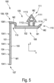
- a sealing profile 100 is provided for the watertight sealing of the connection area between the window sill 300 and the window frame 400 (see Fig. 4 , 5 ).
- the sealing profile 100 is part of a sealing arrangement 1.
- the sealing arrangement 1 has the said sealing profile 100 and at least one sealing element 200 (see Fig. 4 , 6 to 10 ).
- the sealing profile 100 is elongated along a longitudinal axis X. In the assembled state of the sealing profile 100, the longitudinal axis X is parallel to the longitudinal extension of the window sill 300.
- the sealing profile 100 has a first profile leg 101 and a second profile leg 102.
- the first profile leg 101 is arranged in the assembled state between a window sill flange 301 of the window sill 300 and a frame flange 401 of the window frame 400 (see Fig. 4 ).
- the window sill flange 301 is arranged at a rear end of the window sill 300 in relation to a transverse axis Y and is also referred to as an upstand.
- the frame flange 401 serves to fasten the window sill flange 301, whereby in the present case a fastening by means of screws is provided (not shown in detail in the figures).
- the window sill flange 301 and the frame flange 401 are extended longitudinally in the usual way over an entire length of the window sill 300 or the window frame 400, which extends along the longitudinal axis X.
- the frame flange 401 is arranged on a window sill connection profile 403 of the window frame 400.
- the window sill connection profile 403 is connected to an (actual) frame profile 402 of the window frame 400 in a manner not shown in detail.
- the window sill connection profile 403 can be screwed or locked to the frame profile 402.
- the first profile leg 101 has a front sealing surface 103 and a rear sealing surface 104 with respect to the transverse axis Y.
- the rear sealing surface 104 is opposite the front sealing surface 103 with respect to the transverse axis Y.
- the front sealing surface 103 forms a sealing contact with the window sill flange 301.
- the rear sealing surface 104 forms a sealing contact with the frame flange 401.
- the second profile leg 102 projects forwards from the first profile leg 101 along the transverse axis Y and has an upper side 105 and a lower side 106 in relation to a vertical axis Z.
- the lower side 106 lies opposite the upper side 105 in relation to the Vertical axis Z opposite.
- the upper side 105 of the second profile leg 102 serves to seal against a lower side 405 of the window frame 400.
- the lower side 106 of the second profile leg 102 serves to seal against an upper end 3011 of the window sill flange 301.
- the said underside 405 of the window frame 400 is arranged on the (actual) frame profile 402 of the window frame 400.
- the underside 403 points downwards with respect to the vertical axis Z.
- the underside 405 of the frame profile 402 is located above the frame flange 401 with respect to the vertical axis Z.
- the first profile leg 101 and the second profile leg 102 are each longitudinally extended along the longitudinal axis X and parallel.
- the first profile leg 101 is in cross section (see Fig. 4 , 5 ) extends along the vertical axis Z and is thus vertically oriented.
- the second profile leg 102 is in the present case extended in cross section along the transverse axis Y and is thus horizontally oriented.
- the first profile leg 101 is longitudinally extended in cross section between a lower end 107 with respect to the vertical axis Z and an upper end 108.
- the second profile leg 102 is longitudinally extended in cross section along the transverse axis Y between a rear end 109 and a front end 110.
- the sealing profile 100 in the embodiment shown has an approximately L-shaped cross-sectional shape.
- the first profile leg 101 is flat in cross-section and therefore has a belt or band shape.
- the second profile leg 102 is analogously to the first profile leg 101.
- the second profile leg 102 has a form-locking element 111 (see Fig. 5 ).
- the form-locking element 111 projects upwards along the vertical axis Z from the top side 105 of the second profile leg 102.
- the form-locking element 111 is designed for a form-locking connection with a frame groove 406 of the window frame 400.
- the frame groove 406 is along the vertical axis Z from below countersunk upwards into the underside 405 of the window frame 400, in particular the frame profile 402 of the window frame 400.
- the frame groove 405 extends over the entire length of the window frame 400.
- the form-fitting element 111 engages in the frame groove 406 in a form-fitting manner.
- the form-fitting effect acts downwards along the vertical axis Z and forwards and backwards along the transverse axis Y.
- the form-fitting element 111 has a head portion 1111 and two strut portions 1112.
- the head section 1111 is connected to the other sections of the second profile leg 102 by means of the two strut sections 1112.
- the head section 1111 has a cross-section, ie in a YZ plane (see Fig. 5 ), has a triangular shape.
- the two lower corners of the triangular shape (without reference symbol) form undercuts which engage in the frame groove 406 in a form-fitting manner downwards along the vertical axis Z.
- the head section 1111 has a hollow chamber 1113 which is also triangular in shape and is longitudinally extended over the entire length of the form-fitting element 111.
- the two strut sections 1112 are spaced apart from one another along the transverse axis Y.
- a further hollow chamber 1114 is arranged between the two strut sections 1112, which has an approximately square cross-sectional shape.
- the further hollow chamber 114 is also longitudinally extended over the entire length of the form-fitting element 111.
- the form-locking element 1111 is longitudinally extended over an entire length of the second profile leg 102 and thus also over an entire length of the sealing profile 100.
- the upper side 105 of the second profile leg 102 also has a sealing lip 112.
- the sealing lip 112 is elongated along the longitudinal axis X and is designed to form a sealing contact with the underside 405 of the window frame 400.
- the sealing lip 112 lies tightly against the underside 405 of the window frame (see Fig. 4 ).
- the sealing lip 112 is longitudinally extended over the entire length of the second profile leg 102 and thus also of the sealing profile 100.
- the sealing lip 112 forms the said front end 110 of the second profile leg 102.
- the underside 106 of the second profile leg 102 has a receiving groove 113.
- the receiving groove 113 is longitudinally extended along the longitudinal axis X and is sunk upwards into the underside 106 of the second profile leg 102 with respect to the vertical axis Z.
- the receiving groove 113 is plugged together with the window sill flange 301, more precisely: its upper end 3011.
- the upper end 3011 is tightly received in the receiving groove 113.
- the upper end 3011 lies tightly against the receiving groove 113 on both sides with respect to the transverse axis Y.
- the receiving groove 113 forms the said rear end 109 of the second profile leg 102.
- the receiving groove 113 is arranged in the region of the upper end 108 of the first profile leg 101.
- the form-locking element 111 is arranged in the present case with respect to the transverse axis Y between the sealing lip 112 and the receiving groove 113. Starting from an imaginary center of the second profile leg 102, the form-locking element 111 is arranged along the transverse axis Y in the direction of the sealing lip 112 and thus offset to the front.
- the rear sealing surface 104 of the first profile leg 101 has a plurality of projections 1041 positioned at a distance from one another along the vertical axis Z.
- the projections 1041 serve to improve sealing against the frame flange 401.
- the projections 1041 can each also be referred to as a sealing lip.
- the rear end 109 - and thus also the upper end 108 - has a rear sealing lip 1091.
- the rear sealing lip 1091 rests against the frame flange 401 when the sealing profile 100 is in the assembled state.
- the rear sealing lip 1091 projects slightly backwards along the transverse axis Y over the rear sealing surface 104 of the first profile leg 101.
- both the projections 1041 and the rear sealing lip 1091 are longitudinally extended over the entire length of the sealing profile 100.
- the sealing profile 100 is made of different elastomeric plastics M1, M2, namely a first elastomeric plastic M1 and a second elastomeric plastic M2.
- production takes place by means of coextrusion.
- the first elastomeric plastic M1 has a first hardness.
- the second elastomeric plastic M2 has a comparatively lower second hardness.
- the first hardness is 60 Shore and the second hardness is 40 Shore.
- the comparatively less hard elastomeric second plastic M2 is used in the present case to form the Receiving groove 113, the form-locking element 111 and the sealing lip 112.
- the comparatively harder first elastomeric plastic M1 forms the remaining sections of the sealing profile 100.
- the sealing element 200 of the sealing arrangement 1 is in the assembled state in a corner area E (see Fig. 1 , 6 , 7 ) between the window frame 400, the window sill 300 and the reveal 600.
- the sealing element 200 serves to provide a watertight seal for the so-called trade hole. If the trade hole is not sealed or is not sealed properly, water can enter the building. The sealing element 200 primarily counteracts such water ingress via the trade hole.
- sealing arrangement 1 preferably has two sealing elements 200, which are each arranged at corner regions opposite one another along the longitudinal axis X. In the figures, only one sealing element 200 is shown here.
- the sealing element 200 has a cap portion 201 and a foot portion 202 (see Fig. 7 to 10 ).
- the foot section 202 has an inner side 203 located in relation to the longitudinal axis X and an outer side 204.
- the outer side 204 lies opposite the inner side 203 along the longitudinal axis X.
- the foot section 202 is arranged between the reveal 600 and an outer side 501 of the sliding closure 500 with respect to the longitudinal axis X.
- the outer side 204 faces the reveal 600.
- the inner side 203 faces the outer side 501 of the sliding closure 500.
- the cap section 201 protrudes inward from the inner side 203 of the foot section 202 along the longitudinal axis X.
- the cap section 201 has an upper sealing surface 205 and a lower sealing surface 206 with respect to the vertical axis Z.
- the lower sealing surface 206 lies opposite the upper sealing surface 205 along the vertical axis Z.
- Fig. 4 shows that the sealing element 200 is slightly wider than the sealing profile 100 in relation to the transverse axis Y. It is also understood that the sealing element 200 is significantly shorter than the sealing profile 100 in relation to the longitudinal axis X. The length of the sealing element 200 corresponds approximately to a width of the sliding closure 500 in relation to the longitudinal axis X. Further details of the sealing element 200 are given in the Fig. 8 to 10 shown.
- the foot section 202 has a rectangular basic shape in the present case.
- a thickness of the foot section 202 related to the longitudinal axis X is significantly smaller than its extension along the vertical axis Z and along the transverse axis Y. This results in a disc-shaped or plate-shaped shape of the foot section 202 in the present case.
- the foot section 202 extends along the vertical axis Z between a lower end 208 and an upper end 209.
- the cap section 201 is arranged approximately centrally between the lower end 208 and the upper end 209 with respect to the vertical axis Z.
- the foot section 202 is oriented vertically in the assembled state.
- the cap section 201 is oriented horizontally.
- the cap portion 201 is approximately cuboid-shaped and extends with respect to the longitudinal axis X between an outer end 210 and an inner end 211.
- the inner end 211 is positioned on the inner side 203 of the foot portion 202.
- the lower sealing surface 206 of the cap section 201 has a projection 207.
- the projection 207 projects downwards from the lower sealing surface 206 along the vertical axis Z and is designed to engage over an inner end 5021 of the upper side 502 of the sliding closure 500 with respect to the longitudinal axis X (see Fig. 6 ).
- the projection 207 projects beyond the said front end 5021 inwards and downwards.
- the projection 207 is arranged on the inner end 211 of the cap section 201.
- the lower sealing surface 206 of the cap section 201 is inclined forwards with respect to the transverse axis Y.
- the inclination is 5° in this case.
- the inclination of the lower sealing surface 206 thus corresponds to a usual installation gradient of the window sill 300 and thus also of the sliding closure 500.
- the upper sealing surface 205 is aligned parallel to a horizontal plane in the assembled state of the sealing element 200.
- the window frame 400, the window sill 300, the sliding closure 500, the reveal 600 and the sealing arrangement 10 form a component arrangement 10.
- sealing element 200a which can be used as an alternative to the sealing element 200 as shown in the previous figures.
- the sealing element 200a is fundamentally very similar to the sealing element 200, so that in order to avoid repetition, the main differences between the sealing element 200a and the sealing element 200 are discussed below.
- Components and/or sections of the sealing element 200a with the same function are identified with identical reference numerals with the addition of the lower case letter "a".
- the sealing element 200a in turn has a cap section 201a and a foot section 202a.
- the foot section 202a has an inner side 203a located inward with respect to the longitudinal axis X and an outer side 204a.
- the cap section 201a protrudes inward along the longitudinal axis X from the inner side 203a of the foot section 202a.
- the cap section 201a has an upper sealing surface 205a and a lower sealing surface 206a.
- the orientation and function of said sections and surfaces is analogous to what has already been disclosed for the sealing element 200.
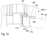
- the sealing element 200a is designed as an end cap K.
- the end cap K can be attached axially along the transverse axis Y and thus in the axial direction of the sliding closure 500 onto the rear end 503 thereof.
- the attachment direction is in Fig. 11 marked with an arrow.
- the end cap K is already attached to the rear end 503 of the sliding closure 500 during production.
- the sliding closure 500 is therefore already present with the end cap K attached. This avoids processing errors by the end user, which ultimately contributes to improved sealing of the corner area E.
- the end cap K has a bottom portion 211a and a rear wall portion 212a.
- the bottom section 211a is opposite the cap section 201a with respect to the vertical axis Z.
- the end cap K is fixed along the vertical axis Z by means of the cap portion 201a and the base portion 211a are held in a form-fitting manner at the rear end 503.
- the base section 211a has a wraparound portion 2011a which is designed to be pushed axially onto a profile leg of the sliding closure 500.
- the wraparound portion 2011a has a U-shape in cross-section, wherein the said profile leg of the sliding closure 500 is arranged and held in the pushed-on state between the opposite legs of the U-shape of the wraparound portion 2011a.
- the rear wall section 212a When plugged in, the rear wall section 212a lies along the transverse axis Y - and thus in the longitudinal direction of the sliding closure 500 - between the first profile leg 101 of the sealing profile 100 and the rear end 503 of the sliding closure 500 (see Fig. 13 ).
- An outer side 214a of the rear wall section 212a rests against the front sealing surface 103 of the first profile leg 101 of the sealing profile 100.
- the inner side 213a (in Fig. 13 shown in dashed lines) rests in a rear end of the sliding closure 500.
- the upper sealing surface 205a of the cap portion 201a rests against the underside 106 of the second profile leg 102a.
- the end cap K may have a support part 215a which is Fig. 13 is indicated by dashed lines.
- the support part 215a can be formed, for example, by a compressible material that can be glued onto the cap section 201a.
- the upper sealing surface 205a is a surface of the support part 215a.
Landscapes
- Engineering & Computer Science (AREA)
- Civil Engineering (AREA)
- Structural Engineering (AREA)
- Specific Sealing Or Ventilating Devices For Doors And Windows (AREA)
Applications Claiming Priority (1)
| Application Number | Priority Date | Filing Date | Title |
|---|---|---|---|
| DE102023121582.5A DE102023121582A1 (de) | 2023-08-11 | 2023-08-11 | Dichtungsprofil zum wasserdichten Abdichten eines Anschlussbereichs zwischen einer Fensterbank und einem Fensterrahmen |
Publications (3)
| Publication Number | Publication Date |
|---|---|
| EP4506531A1 true EP4506531A1 (fr) | 2025-02-12 |
| EP4506531B1 EP4506531B1 (fr) | 2025-07-30 |
| EP4506531C0 EP4506531C0 (fr) | 2025-07-30 |
Family
ID=92264177
Family Applications (1)
| Application Number | Title | Priority Date | Filing Date |
|---|---|---|---|
| EP24193329.0A Active EP4506531B1 (fr) | 2023-08-11 | 2024-08-07 | Dispositif d'étanchéité avec un joint d'étanchéité pour rendre étanche à l'eau une zone de raccordement entre un rebord de fenêtre et un cadre de fenêtre |
Country Status (2)
| Country | Link |
|---|---|
| EP (1) | EP4506531B1 (fr) |
| DE (1) | DE102023121582A1 (fr) |
Citations (6)
| Publication number | Priority date | Publication date | Assignee | Title |
|---|---|---|---|---|
| DE2428003B1 (de) * | 1974-06-10 | 1975-11-27 | Jahn & Treske Eurofit | Dichtungsprofil fuer unterhalb von Fenstersohlbaenken,Attiken o.dgl. befindliche Horizontalfugen |
| DE19723487C1 (de) * | 1997-06-04 | 1998-10-08 | Harry Frey | Schwellenabdeckung |
| AT4959U1 (de) * | 2001-03-22 | 2002-01-25 | Lottmann Fensterbaenke Gmbh | Einrichtung zur dichten befestigung einer aussenfensterbank an einem fensterrahmen sowie anordnung mit einem fensterrahmen und einer solchen einrichtung |
| DE202009007634U1 (de) * | 2009-05-29 | 2010-10-21 | Chempe Gmbh & Co. Kg | Fensterbank-Dichtsystem |
| EP2453095A2 (fr) * | 2010-11-12 | 2012-05-16 | Eurosill GmbH & Co. KG | Connection au mur pour seuils de fenêtre métalliques |
| DE102014015691A1 (de) * | 2013-10-25 | 2015-06-18 | Armin Wigand | Fensterbankeinrichtung |
Family Cites Families (2)
| Publication number | Priority date | Publication date | Assignee | Title |
|---|---|---|---|---|
| AT361686B (de) * | 1979-07-24 | 1981-03-25 | Hrachowina Bauelemente Prod | Anordnung zur seitlichen abdichtung von an sohlbaenken von fenstern angebrachten regen- schutzschienen |
| DE29922126U1 (de) * | 1999-03-30 | 2000-02-24 | SALAMANDER INDUSTRIE-PRODUKTE GMBH, 86842 TüRKHEIM | Profilanordnung |
-
2023
- 2023-08-11 DE DE102023121582.5A patent/DE102023121582A1/de active Pending
-
2024
- 2024-08-07 EP EP24193329.0A patent/EP4506531B1/fr active Active
Patent Citations (6)
| Publication number | Priority date | Publication date | Assignee | Title |
|---|---|---|---|---|
| DE2428003B1 (de) * | 1974-06-10 | 1975-11-27 | Jahn & Treske Eurofit | Dichtungsprofil fuer unterhalb von Fenstersohlbaenken,Attiken o.dgl. befindliche Horizontalfugen |
| DE19723487C1 (de) * | 1997-06-04 | 1998-10-08 | Harry Frey | Schwellenabdeckung |
| AT4959U1 (de) * | 2001-03-22 | 2002-01-25 | Lottmann Fensterbaenke Gmbh | Einrichtung zur dichten befestigung einer aussenfensterbank an einem fensterrahmen sowie anordnung mit einem fensterrahmen und einer solchen einrichtung |
| DE202009007634U1 (de) * | 2009-05-29 | 2010-10-21 | Chempe Gmbh & Co. Kg | Fensterbank-Dichtsystem |
| EP2453095A2 (fr) * | 2010-11-12 | 2012-05-16 | Eurosill GmbH & Co. KG | Connection au mur pour seuils de fenêtre métalliques |
| DE102014015691A1 (de) * | 2013-10-25 | 2015-06-18 | Armin Wigand | Fensterbankeinrichtung |
Also Published As
| Publication number | Publication date |
|---|---|
| EP4506531B1 (fr) | 2025-07-30 |
| EP4506531C0 (fr) | 2025-07-30 |
| DE102023121582A1 (de) | 2025-02-13 |
Similar Documents
| Publication | Publication Date | Title |
|---|---|---|
| DE202014009250U1 (de) | Dichtungsvorrichtung für einen verschiebbaren Flügel als Schiebeflügel oder verschiebbaren Hebe-Schiebeflügel eines Fensters oder einer Tür | |
| DE19745750C5 (de) | Kämpfer-Verbinder für Fenster- und Türrahmen | |
| DE202009016113U1 (de) | Isolierglaseinheit und Tragkonstruktion mit mindestens einer derartigen Isolierglaseinheit | |
| EP0215456A1 (fr) | Profilé creux en matière plastique extrudée pour cadres de portes et fenêtres | |
| DE3308273A1 (de) | Fenster-oder tuerrahmen aus metall | |
| EP4506531B1 (fr) | Dispositif d'étanchéité avec un joint d'étanchéité pour rendre étanche à l'eau une zone de raccordement entre un rebord de fenêtre et un cadre de fenêtre | |
| EP4198243B1 (fr) | Agencement de profilé de cadre | |
| AT501199A1 (de) | Zweiteiliges laibungsanschlussprofil für an putz angrenzende bauteile | |
| EP3141687B1 (fr) | Joint d'etancheite antiretour d'une porte | |
| DE29818846U1 (de) | Fenster- oder Türflügel | |
| EP2131005B1 (fr) | Joint, en particulier pour portes, fenêtres ou façades | |
| DE102011121396A1 (de) | Kraftfahrzeugkarosserie mit Dichtung | |
| DE4412414A1 (de) | Glasfalzdichtung, insbesondere für Fenster oder Türen | |
| EP2372038B1 (fr) | Structure de façades | |
| DE29716361U1 (de) | Gebäudefenster und/oder Gebäudefenstertür | |
| AT528496B1 (de) | Anschlussprofil | |
| EP4174242B1 (fr) | Dispositif d'étanchéité pour étanchéifier le passage entre des éléments de façade d'un élément | |
| EP0458191B1 (fr) | Revêtement de bord pour rebords de fenêtre ou des choses pareilles | |
| EP4357574B1 (fr) | Profilé d'aile et cadre d'ouvrant | |
| DE29813471U1 (de) | Glasdichtung | |
| EP3680438A1 (fr) | Profilé d'étanchéité pour un profilé de cadre et profilé de cadre | |
| DE102011011055B4 (de) | Dichtung für Pfosten-Riegel-Fassaden | |
| DE102009033935A1 (de) | Wohndachfenster | |
| DE2200216C3 (de) | Flügelrahmen aus Metall für Fenster oder Türen | |
| DE3528388A1 (de) | Elastische profildichtung fuer isolierverglasungen |
Legal Events
| Date | Code | Title | Description |
|---|---|---|---|
| PUAI | Public reference made under article 153(3) epc to a published international application that has entered the european phase |
Free format text: ORIGINAL CODE: 0009012 |
|
| STAA | Information on the status of an ep patent application or granted ep patent |
Free format text: STATUS: THE APPLICATION HAS BEEN PUBLISHED |
|
| AK | Designated contracting states |
Kind code of ref document: A1 Designated state(s): AL AT BE BG CH CY CZ DE DK EE ES FI FR GB GR HR HU IE IS IT LI LT LU LV MC ME MK MT NL NO PL PT RO RS SE SI SK SM TR |
|
| STAA | Information on the status of an ep patent application or granted ep patent |
Free format text: STATUS: REQUEST FOR EXAMINATION WAS MADE |
|
| 17P | Request for examination filed |
Effective date: 20250220 |
|
| GRAP | Despatch of communication of intention to grant a patent |
Free format text: ORIGINAL CODE: EPIDOSNIGR1 |
|
| STAA | Information on the status of an ep patent application or granted ep patent |
Free format text: STATUS: GRANT OF PATENT IS INTENDED |
|
| RIC1 | Information provided on ipc code assigned before grant |
Ipc: E06B 1/70 20060101AFI20250313BHEP |
|
| INTG | Intention to grant announced |
Effective date: 20250415 |
|
| GRAS | Grant fee paid |
Free format text: ORIGINAL CODE: EPIDOSNIGR3 |
|
| GRAA | (expected) grant |
Free format text: ORIGINAL CODE: 0009210 |
|
| STAA | Information on the status of an ep patent application or granted ep patent |
Free format text: STATUS: THE PATENT HAS BEEN GRANTED |
|
| AK | Designated contracting states |
Kind code of ref document: B1 Designated state(s): AL AT BE BG CH CY CZ DE DK EE ES FI FR GB GR HR HU IE IS IT LI LT LU LV MC ME MK MT NL NO PL PT RO RS SE SI SK SM TR |
|
| REG | Reference to a national code |
Ref country code: GB Ref legal event code: FG4D Free format text: NOT ENGLISH |
|
| REG | Reference to a national code |
Ref country code: CH Ref legal event code: EP |
|
| REG | Reference to a national code |
Ref country code: DE Ref legal event code: R096 Ref document number: 502024000129 Country of ref document: DE |
|
| REG | Reference to a national code |
Ref country code: IE Ref legal event code: FG4D Free format text: LANGUAGE OF EP DOCUMENT: GERMAN |
|
| U01 | Request for unitary effect filed |
Effective date: 20250811 |
|
| U07 | Unitary effect registered |
Designated state(s): AT BE BG DE DK EE FI FR IT LT LU LV MT NL PT RO SE SI Effective date: 20250822 |
|
| U20 | Renewal fee for the european patent with unitary effect paid |
Year of fee payment: 2 Effective date: 20250819 |
|
| PG25 | Lapsed in a contracting state [announced via postgrant information from national office to epo] |
Ref country code: IS Free format text: LAPSE BECAUSE OF FAILURE TO SUBMIT A TRANSLATION OF THE DESCRIPTION OR TO PAY THE FEE WITHIN THE PRESCRIBED TIME-LIMIT Effective date: 20251130 |
|
| PG25 | Lapsed in a contracting state [announced via postgrant information from national office to epo] |
Ref country code: NO Free format text: LAPSE BECAUSE OF FAILURE TO SUBMIT A TRANSLATION OF THE DESCRIPTION OR TO PAY THE FEE WITHIN THE PRESCRIBED TIME-LIMIT Effective date: 20251030 |
|
| PG25 | Lapsed in a contracting state [announced via postgrant information from national office to epo] |
Ref country code: HR Free format text: LAPSE BECAUSE OF FAILURE TO SUBMIT A TRANSLATION OF THE DESCRIPTION OR TO PAY THE FEE WITHIN THE PRESCRIBED TIME-LIMIT Effective date: 20250730 |
|
| PG25 | Lapsed in a contracting state [announced via postgrant information from national office to epo] |
Ref country code: GR Free format text: LAPSE BECAUSE OF FAILURE TO SUBMIT A TRANSLATION OF THE DESCRIPTION OR TO PAY THE FEE WITHIN THE PRESCRIBED TIME-LIMIT Effective date: 20251031 |
|
| PG25 | Lapsed in a contracting state [announced via postgrant information from national office to epo] |
Ref country code: PL Free format text: LAPSE BECAUSE OF FAILURE TO SUBMIT A TRANSLATION OF THE DESCRIPTION OR TO PAY THE FEE WITHIN THE PRESCRIBED TIME-LIMIT Effective date: 20250730 |
|
| PG25 | Lapsed in a contracting state [announced via postgrant information from national office to epo] |
Ref country code: RS Free format text: LAPSE BECAUSE OF FAILURE TO SUBMIT A TRANSLATION OF THE DESCRIPTION OR TO PAY THE FEE WITHIN THE PRESCRIBED TIME-LIMIT Effective date: 20251030 |
|
| PG25 | Lapsed in a contracting state [announced via postgrant information from national office to epo] |
Ref country code: ES Free format text: LAPSE BECAUSE OF FAILURE TO SUBMIT A TRANSLATION OF THE DESCRIPTION OR TO PAY THE FEE WITHIN THE PRESCRIBED TIME-LIMIT Effective date: 20250730 |
|
| PG25 | Lapsed in a contracting state [announced via postgrant information from national office to epo] |
Ref country code: SM Free format text: LAPSE BECAUSE OF FAILURE TO SUBMIT A TRANSLATION OF THE DESCRIPTION OR TO PAY THE FEE WITHIN THE PRESCRIBED TIME-LIMIT Effective date: 20250730 |
|
| PG25 | Lapsed in a contracting state [announced via postgrant information from national office to epo] |
Ref country code: CZ Free format text: LAPSE BECAUSE OF FAILURE TO SUBMIT A TRANSLATION OF THE DESCRIPTION OR TO PAY THE FEE WITHIN THE PRESCRIBED TIME-LIMIT Effective date: 20250730 |
|
| PG25 | Lapsed in a contracting state [announced via postgrant information from national office to epo] |
Ref country code: SK Free format text: LAPSE BECAUSE OF FAILURE TO SUBMIT A TRANSLATION OF THE DESCRIPTION OR TO PAY THE FEE WITHIN THE PRESCRIBED TIME-LIMIT Effective date: 20250730 |