EP4520603A2 - Dispositif d'actionnement pour un système de freinage à action entièrement ou partiellement hydraulique pour un véhicule - Google Patents
Dispositif d'actionnement pour un système de freinage à action entièrement ou partiellement hydraulique pour un véhicule Download PDFInfo
- Publication number
- EP4520603A2 EP4520603A2 EP24209133.8A EP24209133A EP4520603A2 EP 4520603 A2 EP4520603 A2 EP 4520603A2 EP 24209133 A EP24209133 A EP 24209133A EP 4520603 A2 EP4520603 A2 EP 4520603A2
- Authority
- EP
- European Patent Office
- Prior art keywords
- pressure
- brake
- piston
- valve
- pressure supply
- Prior art date
- Legal status (The legal status is an assumption and is not a legal conclusion. Google has not performed a legal analysis and makes no representation as to the accuracy of the status listed.)
- Pending
Links
Images




Classifications
-
- B—PERFORMING OPERATIONS; TRANSPORTING
- B60—VEHICLES IN GENERAL
- B60T—VEHICLE BRAKE CONTROL SYSTEMS OR PARTS THEREOF; BRAKE CONTROL SYSTEMS OR PARTS THEREOF, IN GENERAL; ARRANGEMENT OF BRAKING ELEMENTS ON VEHICLES IN GENERAL; PORTABLE DEVICES FOR PREVENTING UNWANTED MOVEMENT OF VEHICLES; VEHICLE MODIFICATIONS TO FACILITATE COOLING OF BRAKES
- B60T13/00—Transmitting braking action from initiating means to ultimate brake actuator with power assistance or drive; Brake systems incorporating such transmitting means, e.g. air-pressure brake systems
- B60T13/10—Transmitting braking action from initiating means to ultimate brake actuator with power assistance or drive; Brake systems incorporating such transmitting means, e.g. air-pressure brake systems with fluid assistance, drive, or release
- B60T13/12—Transmitting braking action from initiating means to ultimate brake actuator with power assistance or drive; Brake systems incorporating such transmitting means, e.g. air-pressure brake systems with fluid assistance, drive, or release the fluid being liquid
- B60T13/14—Transmitting braking action from initiating means to ultimate brake actuator with power assistance or drive; Brake systems incorporating such transmitting means, e.g. air-pressure brake systems with fluid assistance, drive, or release the fluid being liquid using accumulators or reservoirs fed by pumps
- B60T13/142—Systems with master cylinder
-
- B—PERFORMING OPERATIONS; TRANSPORTING
- B60—VEHICLES IN GENERAL
- B60T—VEHICLE BRAKE CONTROL SYSTEMS OR PARTS THEREOF; BRAKE CONTROL SYSTEMS OR PARTS THEREOF, IN GENERAL; ARRANGEMENT OF BRAKING ELEMENTS ON VEHICLES IN GENERAL; PORTABLE DEVICES FOR PREVENTING UNWANTED MOVEMENT OF VEHICLES; VEHICLE MODIFICATIONS TO FACILITATE COOLING OF BRAKES
- B60T13/00—Transmitting braking action from initiating means to ultimate brake actuator with power assistance or drive; Brake systems incorporating such transmitting means, e.g. air-pressure brake systems
- B60T13/10—Transmitting braking action from initiating means to ultimate brake actuator with power assistance or drive; Brake systems incorporating such transmitting means, e.g. air-pressure brake systems with fluid assistance, drive, or release
- B60T13/12—Transmitting braking action from initiating means to ultimate brake actuator with power assistance or drive; Brake systems incorporating such transmitting means, e.g. air-pressure brake systems with fluid assistance, drive, or release the fluid being liquid
- B60T13/14—Transmitting braking action from initiating means to ultimate brake actuator with power assistance or drive; Brake systems incorporating such transmitting means, e.g. air-pressure brake systems with fluid assistance, drive, or release the fluid being liquid using accumulators or reservoirs fed by pumps
- B60T13/148—Arrangements for pressure supply
-
- B—PERFORMING OPERATIONS; TRANSPORTING
- B60—VEHICLES IN GENERAL
- B60T—VEHICLE BRAKE CONTROL SYSTEMS OR PARTS THEREOF; BRAKE CONTROL SYSTEMS OR PARTS THEREOF, IN GENERAL; ARRANGEMENT OF BRAKING ELEMENTS ON VEHICLES IN GENERAL; PORTABLE DEVICES FOR PREVENTING UNWANTED MOVEMENT OF VEHICLES; VEHICLE MODIFICATIONS TO FACILITATE COOLING OF BRAKES
- B60T13/00—Transmitting braking action from initiating means to ultimate brake actuator with power assistance or drive; Brake systems incorporating such transmitting means, e.g. air-pressure brake systems
- B60T13/10—Transmitting braking action from initiating means to ultimate brake actuator with power assistance or drive; Brake systems incorporating such transmitting means, e.g. air-pressure brake systems with fluid assistance, drive, or release
- B60T13/12—Transmitting braking action from initiating means to ultimate brake actuator with power assistance or drive; Brake systems incorporating such transmitting means, e.g. air-pressure brake systems with fluid assistance, drive, or release the fluid being liquid
- B60T13/16—Transmitting braking action from initiating means to ultimate brake actuator with power assistance or drive; Brake systems incorporating such transmitting means, e.g. air-pressure brake systems with fluid assistance, drive, or release the fluid being liquid using pumps directly, i.e. without interposition of accumulators or reservoirs
-
- B—PERFORMING OPERATIONS; TRANSPORTING
- B60—VEHICLES IN GENERAL
- B60T—VEHICLE BRAKE CONTROL SYSTEMS OR PARTS THEREOF; BRAKE CONTROL SYSTEMS OR PARTS THEREOF, IN GENERAL; ARRANGEMENT OF BRAKING ELEMENTS ON VEHICLES IN GENERAL; PORTABLE DEVICES FOR PREVENTING UNWANTED MOVEMENT OF VEHICLES; VEHICLE MODIFICATIONS TO FACILITATE COOLING OF BRAKES
- B60T13/00—Transmitting braking action from initiating means to ultimate brake actuator with power assistance or drive; Brake systems incorporating such transmitting means, e.g. air-pressure brake systems
- B60T13/10—Transmitting braking action from initiating means to ultimate brake actuator with power assistance or drive; Brake systems incorporating such transmitting means, e.g. air-pressure brake systems with fluid assistance, drive, or release
- B60T13/66—Electrical control in fluid-pressure brake systems
-
- B—PERFORMING OPERATIONS; TRANSPORTING
- B60—VEHICLES IN GENERAL
- B60T—VEHICLE BRAKE CONTROL SYSTEMS OR PARTS THEREOF; BRAKE CONTROL SYSTEMS OR PARTS THEREOF, IN GENERAL; ARRANGEMENT OF BRAKING ELEMENTS ON VEHICLES IN GENERAL; PORTABLE DEVICES FOR PREVENTING UNWANTED MOVEMENT OF VEHICLES; VEHICLE MODIFICATIONS TO FACILITATE COOLING OF BRAKES
- B60T13/00—Transmitting braking action from initiating means to ultimate brake actuator with power assistance or drive; Brake systems incorporating such transmitting means, e.g. air-pressure brake systems
- B60T13/10—Transmitting braking action from initiating means to ultimate brake actuator with power assistance or drive; Brake systems incorporating such transmitting means, e.g. air-pressure brake systems with fluid assistance, drive, or release
- B60T13/66—Electrical control in fluid-pressure brake systems
- B60T13/662—Electrical control in fluid-pressure brake systems characterised by specified functions of the control system components
-
- B—PERFORMING OPERATIONS; TRANSPORTING
- B60—VEHICLES IN GENERAL
- B60T—VEHICLE BRAKE CONTROL SYSTEMS OR PARTS THEREOF; BRAKE CONTROL SYSTEMS OR PARTS THEREOF, IN GENERAL; ARRANGEMENT OF BRAKING ELEMENTS ON VEHICLES IN GENERAL; PORTABLE DEVICES FOR PREVENTING UNWANTED MOVEMENT OF VEHICLES; VEHICLE MODIFICATIONS TO FACILITATE COOLING OF BRAKES
- B60T13/00—Transmitting braking action from initiating means to ultimate brake actuator with power assistance or drive; Brake systems incorporating such transmitting means, e.g. air-pressure brake systems
- B60T13/10—Transmitting braking action from initiating means to ultimate brake actuator with power assistance or drive; Brake systems incorporating such transmitting means, e.g. air-pressure brake systems with fluid assistance, drive, or release
- B60T13/66—Electrical control in fluid-pressure brake systems
- B60T13/68—Electrical control in fluid-pressure brake systems by electrically-controlled valves
-
- B—PERFORMING OPERATIONS; TRANSPORTING
- B60—VEHICLES IN GENERAL
- B60T—VEHICLE BRAKE CONTROL SYSTEMS OR PARTS THEREOF; BRAKE CONTROL SYSTEMS OR PARTS THEREOF, IN GENERAL; ARRANGEMENT OF BRAKING ELEMENTS ON VEHICLES IN GENERAL; PORTABLE DEVICES FOR PREVENTING UNWANTED MOVEMENT OF VEHICLES; VEHICLE MODIFICATIONS TO FACILITATE COOLING OF BRAKES
- B60T13/00—Transmitting braking action from initiating means to ultimate brake actuator with power assistance or drive; Brake systems incorporating such transmitting means, e.g. air-pressure brake systems
- B60T13/10—Transmitting braking action from initiating means to ultimate brake actuator with power assistance or drive; Brake systems incorporating such transmitting means, e.g. air-pressure brake systems with fluid assistance, drive, or release
- B60T13/66—Electrical control in fluid-pressure brake systems
- B60T13/68—Electrical control in fluid-pressure brake systems by electrically-controlled valves
- B60T13/686—Electrical control in fluid-pressure brake systems by electrically-controlled valves in hydraulic systems or parts thereof
-
- B—PERFORMING OPERATIONS; TRANSPORTING
- B60—VEHICLES IN GENERAL
- B60T—VEHICLE BRAKE CONTROL SYSTEMS OR PARTS THEREOF; BRAKE CONTROL SYSTEMS OR PARTS THEREOF, IN GENERAL; ARRANGEMENT OF BRAKING ELEMENTS ON VEHICLES IN GENERAL; PORTABLE DEVICES FOR PREVENTING UNWANTED MOVEMENT OF VEHICLES; VEHICLE MODIFICATIONS TO FACILITATE COOLING OF BRAKES
- B60T13/00—Transmitting braking action from initiating means to ultimate brake actuator with power assistance or drive; Brake systems incorporating such transmitting means, e.g. air-pressure brake systems
- B60T13/74—Transmitting braking action from initiating means to ultimate brake actuator with power assistance or drive; Brake systems incorporating such transmitting means, e.g. air-pressure brake systems with electrical assistance or drive
- B60T13/745—Transmitting braking action from initiating means to ultimate brake actuator with power assistance or drive; Brake systems incorporating such transmitting means, e.g. air-pressure brake systems with electrical assistance or drive acting on a hydraulic system, e.g. a master cylinder
-
- B—PERFORMING OPERATIONS; TRANSPORTING
- B60—VEHICLES IN GENERAL
- B60T—VEHICLE BRAKE CONTROL SYSTEMS OR PARTS THEREOF; BRAKE CONTROL SYSTEMS OR PARTS THEREOF, IN GENERAL; ARRANGEMENT OF BRAKING ELEMENTS ON VEHICLES IN GENERAL; PORTABLE DEVICES FOR PREVENTING UNWANTED MOVEMENT OF VEHICLES; VEHICLE MODIFICATIONS TO FACILITATE COOLING OF BRAKES
- B60T17/00—Component parts, details, or accessories of power brake systems not covered by groups B60T8/00, B60T13/00 or B60T15/00, or presenting other characteristic features
- B60T17/18—Safety devices; Monitoring
-
- B—PERFORMING OPERATIONS; TRANSPORTING
- B60—VEHICLES IN GENERAL
- B60T—VEHICLE BRAKE CONTROL SYSTEMS OR PARTS THEREOF; BRAKE CONTROL SYSTEMS OR PARTS THEREOF, IN GENERAL; ARRANGEMENT OF BRAKING ELEMENTS ON VEHICLES IN GENERAL; PORTABLE DEVICES FOR PREVENTING UNWANTED MOVEMENT OF VEHICLES; VEHICLE MODIFICATIONS TO FACILITATE COOLING OF BRAKES
- B60T7/00—Brake-action initiating means
- B60T7/02—Brake-action initiating means for personal initiation
- B60T7/04—Brake-action initiating means for personal initiation foot actuated
- B60T7/042—Brake-action initiating means for personal initiation foot actuated by electrical means, e.g. using travel or force sensors
-
- B—PERFORMING OPERATIONS; TRANSPORTING
- B60—VEHICLES IN GENERAL
- B60T—VEHICLE BRAKE CONTROL SYSTEMS OR PARTS THEREOF; BRAKE CONTROL SYSTEMS OR PARTS THEREOF, IN GENERAL; ARRANGEMENT OF BRAKING ELEMENTS ON VEHICLES IN GENERAL; PORTABLE DEVICES FOR PREVENTING UNWANTED MOVEMENT OF VEHICLES; VEHICLE MODIFICATIONS TO FACILITATE COOLING OF BRAKES
- B60T8/00—Arrangements for adjusting wheel-braking force to meet varying vehicular or ground-surface conditions, e.g. limiting or varying distribution of braking force
- B60T8/17—Using electrical or electronic regulation means to control braking
- B60T8/172—Determining control parameters used in the regulation, e.g. by calculations involving measured or detected parameters
-
- B—PERFORMING OPERATIONS; TRANSPORTING
- B60—VEHICLES IN GENERAL
- B60T—VEHICLE BRAKE CONTROL SYSTEMS OR PARTS THEREOF; BRAKE CONTROL SYSTEMS OR PARTS THEREOF, IN GENERAL; ARRANGEMENT OF BRAKING ELEMENTS ON VEHICLES IN GENERAL; PORTABLE DEVICES FOR PREVENTING UNWANTED MOVEMENT OF VEHICLES; VEHICLE MODIFICATIONS TO FACILITATE COOLING OF BRAKES
- B60T8/00—Arrangements for adjusting wheel-braking force to meet varying vehicular or ground-surface conditions, e.g. limiting or varying distribution of braking force
- B60T8/32—Arrangements for adjusting wheel-braking force to meet varying vehicular or ground-surface conditions, e.g. limiting or varying distribution of braking force responsive to a speed condition, e.g. acceleration or deceleration
-
- B—PERFORMING OPERATIONS; TRANSPORTING
- B60—VEHICLES IN GENERAL
- B60T—VEHICLE BRAKE CONTROL SYSTEMS OR PARTS THEREOF; BRAKE CONTROL SYSTEMS OR PARTS THEREOF, IN GENERAL; ARRANGEMENT OF BRAKING ELEMENTS ON VEHICLES IN GENERAL; PORTABLE DEVICES FOR PREVENTING UNWANTED MOVEMENT OF VEHICLES; VEHICLE MODIFICATIONS TO FACILITATE COOLING OF BRAKES
- B60T8/00—Arrangements for adjusting wheel-braking force to meet varying vehicular or ground-surface conditions, e.g. limiting or varying distribution of braking force
- B60T8/32—Arrangements for adjusting wheel-braking force to meet varying vehicular or ground-surface conditions, e.g. limiting or varying distribution of braking force responsive to a speed condition, e.g. acceleration or deceleration
- B60T8/34—Arrangements for adjusting wheel-braking force to meet varying vehicular or ground-surface conditions, e.g. limiting or varying distribution of braking force responsive to a speed condition, e.g. acceleration or deceleration having a fluid pressure regulator responsive to a speed condition
- B60T8/40—Arrangements for adjusting wheel-braking force to meet varying vehicular or ground-surface conditions, e.g. limiting or varying distribution of braking force responsive to a speed condition, e.g. acceleration or deceleration having a fluid pressure regulator responsive to a speed condition comprising an additional fluid circuit including fluid pressurising means for modifying the pressure of the braking fluid, e.g. including wheel driven pumps for detecting a speed condition, or pumps which are controlled by means independent of the braking system
- B60T8/4072—Systems in which a driver input signal is used as a control signal for the additional fluid circuit which is normally used for braking
- B60T8/4081—Systems with stroke simulating devices for driver input
-
- B—PERFORMING OPERATIONS; TRANSPORTING
- B60—VEHICLES IN GENERAL
- B60T—VEHICLE BRAKE CONTROL SYSTEMS OR PARTS THEREOF; BRAKE CONTROL SYSTEMS OR PARTS THEREOF, IN GENERAL; ARRANGEMENT OF BRAKING ELEMENTS ON VEHICLES IN GENERAL; PORTABLE DEVICES FOR PREVENTING UNWANTED MOVEMENT OF VEHICLES; VEHICLE MODIFICATIONS TO FACILITATE COOLING OF BRAKES
- B60T8/00—Arrangements for adjusting wheel-braking force to meet varying vehicular or ground-surface conditions, e.g. limiting or varying distribution of braking force
- B60T8/32—Arrangements for adjusting wheel-braking force to meet varying vehicular or ground-surface conditions, e.g. limiting or varying distribution of braking force responsive to a speed condition, e.g. acceleration or deceleration
- B60T8/34—Arrangements for adjusting wheel-braking force to meet varying vehicular or ground-surface conditions, e.g. limiting or varying distribution of braking force responsive to a speed condition, e.g. acceleration or deceleration having a fluid pressure regulator responsive to a speed condition
- B60T8/36—Arrangements for adjusting wheel-braking force to meet varying vehicular or ground-surface conditions, e.g. limiting or varying distribution of braking force responsive to a speed condition, e.g. acceleration or deceleration having a fluid pressure regulator responsive to a speed condition including a pilot valve responding to an electromagnetic force
- B60T8/3615—Electromagnetic valves specially adapted for anti-lock brake and traction control systems
- B60T8/3675—Electromagnetic valves specially adapted for anti-lock brake and traction control systems integrated in modulator units
- B60T8/368—Electromagnetic valves specially adapted for anti-lock brake and traction control systems integrated in modulator units combined with other mechanical components, e.g. pump units, master cylinders
Definitions
- the present invention relates to an actuating device for a fully or partially hydraulically acting braking system for a vehicle, comprising a master brake cylinder having a piston-cylinder unit with a piston and a working chamber, wherein the working chamber is hydraulically connected or connectable to a reservoir and a pedal feel simulator and is mechanically connected via an actuating device, in particular a brake pedal, and the working chamber is connectable to at least one brake circuit via at least one normally open valve, and that at least one hydraulically acting wheel brake assigned to a brake circuit, each of which is assigned at least one dedicated controllable switching valve, with which the wheel brake is connectable to the respective brake circuit for pressure build-up and pressure reduction, in particular in brake booster mode, as well as a pressure supply driven by an electric motor, the piston of which is adjustable in the cylinder by means of the electric motor, at least one valve arrangement with solenoid valves for wheel-individual pressure control, and at least one electrical control unit for controlling at least valves of the valve arrangement and the pressure supply motor, and at least one controlled outlet
- the focus here is on the pressure supply, where braking force or pressure build-up must be ensured even without the driver's foot.
- the electronic control system must also be designed accordingly for this function.
- Level 3 and especially Level 4 the ABS function must also be guaranteed even in the event of a fault.
- DE 10 2017 222 450 discloses a hydraulic system with a single master cylinder, redundant pressure supply, isolation valves to the master cylinder, and a travel simulator.
- a bypass valve between the two brake circuits allows the second pressure supply to supply both brake circuits in the event of a pressure supply failure.
- This normally open valve is extremely safety-critical, since a valve failure, for example, and a brake circuit failure, can result in total brake failure. Furthermore, the valve complexity is very high.
- the DE 10 2017 222 435 and DE 10 2016 225 537 feature a similar concept, but with an electric pedal, reduced pressure supply, and a bypass valve. All systems use a so-called exhaust valve for the ABS function during pressure reduction. If a dirt particle gets caught in the valve seat when the valve opens, this can cause a brake circuit failure during the next braking application.
- DE 10 2017 207 954 shows a system concept with redundant pressure supply and without outlet valves for ABS pressure control.
- the so-called multiplex process which is already used in DE 102005055751 and DE 102009008944 A1
- the ABS pressure control is performed by the pressure supply using volume measurement and pressure information.
- the switching valves for pressure control are also used redundantly. A safety risk arises if the piston seal or a check valve to the reservoir fails and the switching valve leaks due to dirt particles, which also results in total brake failure.
- the packaging or construction volume of the braking system is also of great importance. Especially for systems with HAD (semi-automated) and FAD (fully automated driving), many variants from Level 2 with tandem master cylinder (THZ) or single master cylinder (HZ) to Level 5 without THZ or HZ must be considered in the design. In particular, 3-5 concepts with two pressure supplies or pressure supply devices (DV) are difficult to implement in the packaging with a small construction volume. Examples of packaging are EP2744691 with vertical arrangement of the pressure supply (DV) to the HZ axis and DE 2016032116160400 with a parallel arrangement of the pressure supply unit to the HZ axle, which requires a smaller overall width. A simple master brake cylinder generally requires a braking system with multiple redundancies.
- the master brake cylinder is designed with redundant and diagnosable seals, and if additional redundancies are provided in the pressure supply (e.g., pressure supply with 2x3 phase connection, redundancy in the vehicle electrical system connection), and in particular, if additional modules can be used for braking (e.g., electric parking brake, electric drive motor).
- the pressure supply e.g., pressure supply with 2x3 phase connection, redundancy in the vehicle electrical system connection
- additional modules e.g., electric parking brake, electric drive motor.
- the object of the present invention is to create a very cost-effective, short and narrow 1-box solution for automated driving of levels 2 to 3, which is also modular for other solutions based on it with later integration of a second pressure supply.
- a compact package with an integrated pressure supply consisting of a pressure supply device, valves, in particular solenoid valves, combined in a hydraulic unit, at least one electronic control and regulation unit, at least one reservoir, a single master brake cylinder, pedal stroke sensors, and a travel simulator with pistons.
- the invention provides various variants of modular actuation systems for brake systems, which contain as many identical parts as possible for production and assembly.
- Housing A is preferably manufactured from an extruded molded piece, which is ideal for fastening and assembly using caulking technology.
- the interface to the ECU control unit is similar to ABS/ESP.
- the brake master cylinder HZ with all of the aforementioned components (housing C) can be screwed to housing A - this applies to all variants except variants e and f.
- housing C is mounted as an assembly separate from the unit on the bulkhead, and the hydraulic line from the brake master cylinder HZ is connected to housing A.
- a is mounted as an assembly separate from the unit on the bulkhead, and the hydraulic line from the brake master cylinder HZ is connected to housing A.
- the reservoir VB is located in housing A with two connections to the brake circuits or with an additional connection to the pressure supply DV.
- the float in the reservoir VB contains a target with a connection to the sensor element in the ECU control unit.
- the motor can preferably be connected to housing A via an intermediate housing, which is preferably made of plastic.
- the sensor required for motor commutation and piston position can be mounted on the motor housing, preferably in the motor axis on the side opposite the piston, and connected to the ECU control unit.
- the sensor is located in an additional housing to the ECU.
- an additional small circuit board can be installed on the main PCB for a second connection of the solenoid coil.
- the packaging shown meets the requirements for modularity and small construction volume and is also very low in cost and weight.
- a special design of the reservoir allows its filler neck or opening to be advantageously positioned on or in front of the front of the housing of the electronic control unit or the actuating device, so that it is easily accessible.
- the connection from the front filler neck to the rear of the control unit housing, which bypasses the electronic control unit, allows the actual reservoir to be conveniently located behind the control unit.
- the side or central area of the reservoir can advantageously be designed to be narrow, so that the actuating device is not, or only slightly, wider than with a conventional reservoir.
- Each wheel brake is assigned a switching valve. Unless additional outlet valves are provided, the corresponding switching valve must be opened to change the pressure in the respective wheel brake, with the pressure supply device increasing or decreasing the pressure by moving its piston accordingly. Once the pressure in the wheel brake is regulated, the corresponding switching valve is closed again, and a pressure change can be made in another wheel brake.
- At least one outlet valve for at least one wheel brake or brake circuit it is possible to provide a highly dynamic ESP and/or ABS function with just one pressure supply device, with pressure being built up via the switching valves assigned to the wheel brakes.
- the outlet valve assigned to a wheel brake can then be used to directly release the pressure into the reservoir when the wheel brake switching valve is closed, allowing a pressure change in another wheel brake or the other brake circuit to be made simultaneously with the pressure supply device.
- Outlet valves should be installed particularly on hydraulic consumers with large volumes (e.g. on wheel brakes of the front axle) or at a central location between isolation valves that separate the brake circuits ( Fig. 5 ). Depending on the brake circuit design (diagonal or black-and-white), the outlet valves are arranged at different points in the hydraulic system.
- the exhaust valves are operated closed.
- the multiplex process is primarily used according to DE 102005055751 and DE 102009008944 A1
- the outlet valve(s) is used to reduce pressure, with pressure reduction preferably taking place with the assistance of the pressure sensor signal. This means that the brake circuit is only opened to the reservoir in very rare cases, which has decisive advantages in terms of reliability.
- the switching valves are arranged in such a way that a pressure present in a wheel brake (RB) applies force to the valve actuator of the switching valve (SV) away from its valve seat.
- volume is supplied from the reservoir to the brake circuit when the pressure supply isolating valve is closed.
- Fig. 1 shows the side view of the integrated unit housing A with valve arrangement HCU, which contains the components MV, pressure transducer DG, piston for DV1 and fastening of the motor of DV1.
- the components such as valves, solenoid valve MV, pressure transducer DG are preferably fastened to a flow-pressed or extruded block 24, e.g. the MV preferably by caulking or clinching, which also includes its sealing.
- the lower part shows the piston 8 of the pressure supply unit DV1 with return spring and housing cover 7, which is preferably driven by the spindle and ball screw drive KGT (not shown) via the motor 2. In housing A, this is screwed to the HCU block 24 via an intermediate housing 3 with fastening screws.
- the reservoir VB2 is provided with two connections 9a and 9b are connected to brake circuits 1 and 2.
- the suction valve SV for the pressure supply DV is located in the housing as an extension of 9c.
- the reservoir VB has a filler neck VB V with a filler opening 100 which can be closed by means of a cover 101 and which extends in front of the housing of the ECU, wherein a central area VB M extends laterally on the housing of the ECU to the rear of the unit and opens into a rear area of the reservoir VB H , so that hydraulic medium can pass from the filler neck VB V into the rear area VBH.
- the sensor housing 3 with the angle of rotation sensor is connected to both the motor 2 and the ECU 18 via a preferably flexible circuit board (not shown) with the intermediate housing.
- the connectors are attached to the top of the control and regulation unit ECU; in the redundant ECU, there are two connectors.
- the corresponding connecting line to the master brake cylinder HZ is provided at 11.
- the reservoir VB can, as usual, contain a level sensor (NS) with a float, whereby the target and sensor element are arranged in the control and regulation unit ECU, which is preferably designed redundantly for levels 4 and 5.
- the master brake cylinder HZ is arranged behind the valve arrangement block HCU and is screwed to the HCU block 24 with fastening screws 13.
- the motor sensor 34 for electronic commutation and control of the piston position.
- the motor can be equipped with various drive types, e.g., gear, trapezoidal, or spindle 57 with ball screw 58, as shown in Fig. 1a shown, combined.
- Various sensor types can be used, such as segment sensors with inductive or magnetic field-sensitive sensors, or sensors located in the motor or transmission axis. These sensors are particularly simple in design and consist of a sensor target, e.g., in the form of a two- or multi-pole magnet, and a magnetic field-sensitive sensor element, e.g., in the form of a Hall sensor, GMR sensor, or similar.
- This sensor element 34 is electrically connected to the electronic control unit (ECU), which is attached to the engine either directly or via an intermediate housing.
- the sensor element 34 is preferably housed in a sensor housing consisting of an outer housing part 52 and an inner housing part 52a and accommodates, among other things, a printed circuit board 22 on which the sensor element 34 can be arranged.
- an elastic part 61 is provided according to the invention.
- tolerances in all three directions x, y, z must be compensated.
- the sensor housing is advantageously divided into two parts: an outer housing 52 and an inner housing 52a, with the housing parts 52, 52a being connected to one another using conventional joining techniques such as welding or gluing, and are preferably made of plastic.
- the sensor housing is also fastened to the motor housing 62, preferably at two points.
- the sensor circuit board 22 is flexible in its upper part relative to the connector strip in order to accommodate the aforementioned tolerances.
- a flex PCB flexible printed circuit board
- the electrical connection 22a from this flexible circuit board 22 to the main circuit board 23 of the electronic control unit (ECU) is preferably made via the particularly fail-safe connector strip 51 with press-in contacts.
- the housing 18 of the electronic control unit (ECU) has a recess with a cover.
- the sensor housing 52, 52a is connected to a projection of the ECU housing 18 and fixed thereto.
- An elastic part 61 which can be, for example, a flexible elastic seal or a sealing bellows, is located between them.
- the elastic part is preferably designed as a lip seal. This flexible and elastic seal 61 thus serves to compensate for 3-axis tolerances.
- the electrical connection from the motor winding to the circuit board 23 is established via a standard plug-in contact.
- the sensor arrangement shown additionally enables the measurement of the rotor eccentricity, which acts on the spindle and generates transverse forces on the piston 8.
- a measuring device 53 arranged on the rotor or the spindle nut 56 which in the simplest case is a measuring flange or a disk, is used to measure the rotor eccentricity.
- the rotor eccentricity also has an effect in the axial direction and can be measured using laser technology.
- the outer sensor housing part 52a has an opening 152 in its lower region 52", which is closed with a sealing plug 54 after the measurement.
- the surface of the measuring device 53 can have markings, be provided with a coating, and/or be profiled on its side facing the outer sensor housing part 52 for the purpose of measurement.
- the lower region 52" is fastened to the motor housing 62 by means of a fastening screw 55.
- the Figure 1b shows a space-saving schematic design of a storage container VB, which has a front area VB V , a middle area VBM and a rear area VB H.
- the front area VB V has an upper filling opening 100, which can be closed with the lid 101.
- the reservoir VB surrounds the housing B of the electronic control unit ECU on three sides, namely its front side ECU-V, its side wall ECU-S, and its rear side ECU-H.
- the rear side ECU-H faces the splash guard SW.
- the reservoir VB can also rest against the rear wall of the housing of the valve assembly HCU or engage behind it, as shown in Figure 7a.
- Figure 2 shows a slightly modified embodiment compared to the unit shown in Figure 1.
- Figure 2a shows the view from the front.
- the outline contour can still be accommodated within the small vacuum of 8" and is therefore suitable for installation on the bulkhead.
- the great advantage is the overall width of approximately 50% of the above-mentioned BKV, which is very advantageous for right- and left-hand drive vehicles.
- the overall length is also considerably shorter compared to the above-mentioned BKV, thus forming a basis for a broad application of the inventive Modular concept.
- the various housings A, B, C, and VB are also provided.
- Housing B for example, is located behind the HCU block 24 and is bolted and sealed to it, as with ABS.
- the PCBs can be separated by sealed bridges in the control and regulation ECU housing with the two redundant circuits. Redundancies also advantageously cover or eliminate potential circuit breakage. The remaining electronic connections from the motor to the PCB are also important.
- Fig. 3 shows the HZ master brake cylinder with housing, in which the HZ piston 33 and WS piston with spring for the counterforce and pedal characteristics are installed.
- the travel simulator piston can also be housed in block A or housing A.
- the piston also has redundant seals 45 with a throttle Dr to the interior. If seal 45 fails, the failure is detected via the leakage flow and the failure is no longer relevant. This throttle Dr with a small leakage flow allows the diagnosis of the failure of the first seal.
- the travel simulator piston is supported on flange 12 and therefore does not require a separate closure piece.
- the HZ piston 23 with return spring 50 is arranged parallel to the travel simulator piston.
- the piston can be guided in sliding rings 48 with low friction, which also has less impact on the sealing effect of the piston.
- a separate bearing part 49 is used for the sliding rings and seals.
- This bearing part is supported on the flange and also supports the stop of the piston 23 via a stop ring 28.
- a force-displacement sensor KWS 30 can be installed in the HZ piston.
- Sensor rods 31 and 31a are connected to the piston 23 and the pedal tappet. These rods are connected to a locking coupling 32-34, each with the piston and pedal tappet.
- This coupling consists of a ball 34 with a spring 33 in the housing 22. This prevents the pedal tappet from becoming blocked if a sensor rod jams.
- Fig. 4 shows the arrangement of two alternative designs of the pedal travel sensors.
- the first variant with rack 38, gear 37, drive shaft 36 to target 35 and sensor element 34 on PCB 23 has already been DE102015104246 This version requires little installation space and is cost-effective.
- a guide part 39 e.g., with a pin, is pressed into the sensor rod. This is guided in the upper part in a guide rail 40 to minimize angular rotation, which affects the target 41.
- This target acts on an inductive sensor 42 with evaluation circuitry and is connected to the main PCB 23 and located in the ECU housing 14.
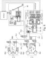
- the Figure 5 shows the basic elements of a controllable brake system consisting of a master brake cylinder HZ with travel simulator WS and reservoir VB, a pressure supply device DV1, whereby the pressure supply device DV1 is an electromotive piston control.
- the pressure supply device DV1 acts together with a valve circuit on the wheel brake cylinders RZ, which transmit the controlled wheel pressure, e.g. in the case of ABS, to the Brake. This corresponds to the state of the art.
- the pressure can be regulated in both brake circuits BK1 and BK2 via the two connecting valves BP1 and BP2.
- hydraulic system according to the invention should have a high level of fault tolerance for semi-automatic (HAD) or fully automatic driving (FAD).
- HAD semi-automatic
- FAD fully automatic driving
- the pressure supply device DV1 acts from the brake circuit BK1 into the brake circuit BK2 via the hydraulic lines 1, 2 and 5 via the switching valves SV to the wheel brakes RB.
- the invention therefore provides two redundant valves BP1 and BP2 to enable the connection to the brake circuit BK2 from the first pressure supply device DV1.
- Dormant faults in the valves BP1 and BP2 are detected by the pressure sensor by short-circuiting the valves when the pressure changes. During this phase, the pressure must remain constant. If the first pressure supply device DV1 fails, e.g.
- valves are preferably normally open valves so that if the pressure supply device DV1 fails, the master brake cylinder HZ can act on both brake circuits BK1 and BK2. If pressure is reduced by opening the ZAV or FV valves, the two connecting switching valves open automatically due to the differential pressure acting without their own electrical control.
- the pedal movement is measured by redundant pedal travel sensors (PS), which are simultaneously connected to a KWS measuring element according to WO2012/059175 A1 act.
- the pressure supply device DV1 is controlled by the signal from the pedal travel sensors, whereby the piston control causes the volume flow in the main hydraulic line 1 in the brake circuit BK1 and via the redundant BP1 and BP2 valves into the brake circuit BK2.
- the master brake cylinder HZ can be connected to the brake circuits BK1 or BK2 via line 3, with the valve FV being arranged in line 3 to close it. This connection is only effective in the fallback level. If the line is connected to the connecting line of the two switching valves BP1 and BP2, the two valves BP1 and BP2 form a further redundancy. A conventional connection from the FV directly into one of the two brake circuits BK1, BK2 would result in the brake circuit and thus the pressure supply acting on the HZ piston if the valve FV were leaking, which conventionally leads to the pressure supply being switched off.
- valve FV Different pressures or pressure levels from the master brake cylinder and the brake circuits BK1 and BK2 act on the valve FV. In the worst case, this can lead to, for example, failure of the on-board power supply or the control and control unit ECU that an unfavorable pressure difference prevails at the closed valve FV and the valve FV cannot open, so that a pressure reduction P ab is not possible.
- another switching valve can be connected in parallel to the valve FV, with the outputs and inputs of the valves being interchanged and connected to line 3, so that for any pressure difference it is ensured that at least one of the two valves opens automatically due to the differential pressure, i.e. even without current.
- the back pressure at the valves is advantageously reduced as a result. If the valve FV fails or leaks, the travel simulator WS does not fail.
- a brake circuit in the wheel cylinder fails, the corresponding inlet valve (EV) or switching valve (SV) is conventionally closed, thus eliminating the failed wheel circuit.
- a leaking EV/SV causes the brake circuit or the entire pressure supply to fail.
- valves BP2 and BP1 provide additional safety, ensuring that the pressure supply does not fail.
- a failure of brake circuit BK1 due to a malfunctioning switching valve (SV) results in a failure of the pressure supply (DV1), which causes the pressure supply to all still functioning wheel brakes to be supplied via the other pressure supply device (DV2).
- the pressure supply When the pressure supply is active, pressure build-up always occurs via the pressure supply.
- either the pressure supply or the central outlet valve ZAV can be used. Pressure reduction then occurs by retracting the pressure supply piston or by PWM operation of the ZAV.
- the pressure signal from the pressure sensor can be used.
- an outlet valve AV for at least one wheel brake as an alternative or in addition to the ZAV valve.
- the AV is preferably used on wheel brakes with a large volume, i.e., front wheel brakes.
- two outlet valves AV can be used instead of one outlet valve (not shown).
- an outlet valve AV can also be provided for each brake circuit, so that the pressure in this brake circuit is reduced via the outlet valve AV and, at the same time, the pressure in the another brake circuit.
- the volume flow also passes through valves BP1 or BP2, so a leaking ZAV is not critical for normal operation, since if the central discharge valve ZAV fails, pressure is controlled via the pressure supply device DV1. Furthermore, the fault, even if dormant, is immediately detected by the ZAV through a pressure change or increased volume flow from the pressure supply device DV1.
- an additional discharge valve can also be connected in series with the outlet valve ZAV.
- the causes of failure in the master brake cylinder (HZ) and travel simulator (WS) are usually the seals.
- an additional seal D3 with a restrictor can be installed in the return line to the reservoir (VB) to enable early diagnosis of seal failure. This allows a leak to be detected via a small additional pedal movement via the pedal stroke sensors. The low stress on the HAD and FAD must be taken into account.
- the same solution is also used for the WS piston with redundant seals, diagnosis as above for D3 via pedal movement.
- control of the brake booster is still possible even with these failed seals, albeit with altered pedal characteristics.
- the failure rate for the failure of two seals is extremely low, almost in the range of ⁇ 10 -10 /year.
- the pressure supply unit DV1 can also be equipped with redundant seals, as with the master brake cylinder HZ. described, can be equipped with D6 with a throttle between D6 and D5. If the suction valve is connected directly to the connection on PD1, then suction begins immediately on the piston's return stroke, with the advantage that high suction performance is achieved even at low temperatures. A failure or leak in the SV will, in extreme cases, cause the DV to fail.
- a compromise lies in connecting the SV at approx. 60% of the stroke. This means that 40% of the stroke is possible without the effect of a leaking SV and at the same time a suction effect is achieved in the normal temperature range. With a small restriction mentioned above, the volumetric delivery of the piston is ensured by redundancy. Furthermore, the motor can be controlled via a redundant 2x3-phase winding, so that the DV only fails if the ball screw gear blocks.
- the ABS function via multiplex operation MUX and the pressure supply device DV1 is carried out as in WO 2006/111393 A1 described.
- Extended MUX functions are achieved by a central relief valve ZAV. If, when the pressure p auf in the brake circuit BK1 is built up, a pressure reduction p ab in the other brake circuit BK2 is necessary at the same time, this takes place via the central relief valve ZAV and the simultaneously closed valve BP1.
- the multiplex system MUX is only loaded by two wheel brakes RB1, RB2 in the brake circuit BK1, i.e. a pressure build-up Pauf and pressure reduction Pab cannot take place in the wheel brakes RB1 and RB2 of the brake circuit BK1 at the same time.
- a relief valve AV1, AV2 can be used in the respective brake circuit to reduce the pressure p ab in order to relieve the MUX.
- the relief valve AV can be arranged or connected either between the switching valve SV and a connecting switching valve BP1, BP2 or between the wheel brake and the associated switching valve SV, so that a direct pressure reduction Pab can take place via the relief valve to a reservoir VB. This is particularly useful for reducing the pressure in the front wheels.
- the central discharge valve (ZAV) is not required with this alternative.
- pressure control for the above-mentioned MUX operation is achieved via volume measurement and the piston movement of the pressure supply device DV1, also taking into account the pressure-volume characteristic (pV characteristic).
- pV characteristic pressure-volume characteristic
- This also allows volume metering for pressure build-up. It is advantageous here to use a serial rather than simultaneous pressure build-up.
- the valve dimensioning and the back pressure at the valve must be taken into account, especially for valves BP1 and BP2 when pressure builds up rapidly in the wheel circuits.
- the back pressure of the above-mentioned valves acts as a pressure difference between the brake circuits BK1 and BK2.
- the control and regulation unit is a component of the entire system and the packaging.
- a redundant or partially redundant ECU is required for fail-safe operation.
- This partially redundant ECU can also be used for certain functions in addition to the redundant ECU.
- the valves are or should be driven redundantly via separate valve drivers and a disconnect switch that shuts down a failed valve driver.
- a redundant on-board power supply connection is also required for redundancy of the ECU control and regulation unit.
- a 48V connection can also be used to connect the motors. The advantage of 48V is greater dynamic response. If the motor fails at the DV1 pressure supply unit at 48V, emergency operation at 12V with approximately 50% power is possible, resulting in reduced dynamic response and cost savings. This requires the motor to be configured for 24V, for example.
- a pressure sensor DG is used in brake circuit BK2, and possibly also in BK1. If the pressure sensor fails, pressure control can be achieved via the current measurement of the motors and position control of the piston via the p-v characteristic curve.
- the pressure sensor DG1 can be used as shown in the Figure 5 shown. Alternatively, it can also be replaced or supplemented by one of the two pressure sensors DG2, DG3 shown in dashed lines.
- the pressure sensor DG2 should advantageously be used to measure the pressure in the connecting line VL. This advantageously allows the pressure to be controlled via the outlet valve AV and the pressure sensor DG2 when the pressure P ab in the brake circuit BK2 decreases, if the pressure supply device DV1 in the brake circuit BK1 operates the pressure control, e.g. using a multiplex process.
- the pressure change in brake circuit BK2 can be controlled via the pressure sensor DG2 and the second pressure supply device DV2, which is directly connected to line 5, provided the two connecting valves BP1 and BP2 are closed.
- the pressure supply device DV1 then controls, for example, via volume and current measurements. Calibration can be performed, for example, whenever the pressure supply device DV1 drives the pressure change in both brake circuits BK1 and BK2.
- a separating valve TVBK1 is arranged in line 4 so that the brake circuit can be separated again from the pressure supply DV1.
- Fig. 6a shows the application of a 2-circuit double-stroke piston, whose forward stroke feeds BK1 via V1 and BK2 via V2. Both circuits of the DHK can feed into the other brake circuit BK via BP1 and BP2.
- the volume of the DHK must be WO2016/023994 A1and WO2016/023995 A1 known, via the valves V3 and V4 in the storage tank VB.
- the Figure 7 shows a schematic representation of a possible embodiment of a braking system with wheel brakes RB1 and RB2 on the front axle VA and the wheel brakes RB3 and RB4 on the rear axle, wherein an electric drive motor EM is provided to drive the rear axle HA.
- the braking system consists of a single pressure supply unit (DV1), an actuation unit (BE), and a higher-level control and regulation unit (M-ECU).
- the pressure supply unit (DV1) has two independent control and regulation units (DV-ECU1 and DV-ECU2), each of which controls one of the two winding or phase systems of the drive motor of the pressure supply unit (DV1), which are formed here by three-phase systems. Additionally, redundant signal lines (DS1 and DS2) can be provided.
- Switching valves are provided for connecting or disconnecting the pressure supply unit DV1 to the wheel brakes.
- the dashed lines represent signal transmission lines that connect the M-ECU control unit to the brake system components.
- the traction motor EM communicates with the control unit M-ECU and can be used to drive as well as brake the rear axle VA.
- a pressure supply device DV1 is used to build up pressure in the hydraulically acting wheel brakes RB1-RB4.
- This pressure supply device has an electric motor drive M1 that is controlled by the control and regulating unit DV-ECU.
- the pressure supply device DV1 can also have a motor current measuring device i/U, at least one temperature sensor T/U and a rotor angle sensor ⁇ /U, whose signals can be used for pressure regulation.
- the motor M1 drives a piston KB via a spindle drive.
- This piston is displaceably mounted in a cylinder of the pressure supply device DV1 and defines a pressure chamber, in order to build up, maintain or reduce pressure there.
- the pressure chamber is connected to the isolation valves TV1, TV2 via a hydraulic line.
- a brake circuit failure does not result in a total failure of the braking system. If brake circuit BK1 fails, braking force can still be generated in brake circuit BK2 via the pressure supply and the electric motor EM. If brake circuit BK2 fails, braking force can be generated in brake circuit BK1 (front axle) via the driver's actuation unit or the pressure supply DV1. This means that the legal requirements for minimum deceleration can be met even if the brake circuit fails. Since the pressure supply is also redundant, high availability can be achieved. The residual risk lies in the spindle drive jamming, which must be safeguarded by appropriate quality measures.
- the pressure in the hydraulic line can be determined using the pressure sensor p/U.
- the pressure can be controlled either with the aid of the pressure sensor p/U. However, pressure control can also be achieved via current measurement using the motor current measuring device i/U as well as the angle sensor ⁇ /U and a stored Pressure-volume characteristic curve, since the motor torque is proportional to the pressure in the pressure chamber and also proportional to the motor current i.
- the M1 motor has two separate winding systems with 2x3 phases. The number of phases can of course be changed according to the respective requirements. If one winding system fails, the M1 motor can still be operated with reduced power. This already creates a significant level of redundancy.
- the DV-ECU control and regulation unit can also be designed redundantly, so that, for example, an independent DV-ECU1 and DV-ECU2 control and regulation unit can be provided, each controlling a phase system of the M1 motor. This means that even if one DV-ECU1 or DV-ECU2 control and regulation unit fails, the braking system can still be operated safely.
- the pressure supply device DV1 can be optionally connected to or separated from the hydraulic line HL6 or the first brake circuit BK1.
- the hydraulic lines HL1 and HL2 which are connected to the wheel brakes, can be optionally connected to the hydraulic line HL6. If pressure is to be built up in the wheel brake RB1 of the front axle VA, this is done via open valves TV and SV1, with valves AV1, SV2 and FV closed and piston KB adjusted by motor M1.
- the piston KB can be retracted with the same valve switching, or the outlet valve AV1 is opened, allowing the pressure in the wheel brake RB1 to be reduced into the reservoir VB.
- the pressure build-up in the wheel brake RB2 occurs in a similar way.
- the pressure in the wheel brakes RB1 and RB2 can also be built up and released simultaneously. It is also possible to build up pressure in one wheel brake using the pressure supply device DV1 and simultaneously reduce pressure in the other wheel brake via the associated outlet valve AV.
- the actuating device BE can be used to reduce pressure in one or both brake circuits.
- the actuating device BE has a brake pedal that acts on a piston that defines a pressure chamber. The piston then forces hydraulic fluid from the pressure chamber into the brake circuit(s), thereby building up brake pressure in one or all wheel brakes.
- the switching valves are preferably designed as normally open valves.
- the Figure 8 shows another possible variant, where in contrast to the Figure 7 only one isolating valve TV1 is provided, which is located in the housing of the pressure supply device DV1.
- electric parking brakes EPB are provided on the rear axle HA as a further option for generating braking torque in the event of a fault. If the pressure supply DV1 fails, pressure can be built up in the wheel brakes RB1-RB4 in both brake circuits BK1 and BK2 by means of the master brake cylinder HZ via the normally open valve FV. If a wheel circuit fails, the respective switching valve assigned to the leak must be operated closed to prevent this from leading to a complete failure of the braking system.
- the Figure 9 shows a variant in which only one isolating valve TV1 is provided, so that in contrast to the variant of the Figure 8 only in the brake circuit of the front axle VA, pressure can be built up via the master brake cylinder HZ in the event of failure of the pressure supply device DV1.
- the isolating valve is located in the valve arrangement HCU.
- the failure of the pressure supply is not too critical, since an electric traction motor EM is available in the brake circuit BK2 and the actuation unit with master brake cylinder HZ is available in the brake circuit BK1 in the event of a failure of the pressure supply DV1.
- the Figure 10 shows a variant in which no electric motor is mounted on an axle and only a separating valve TV1 is provided.
- This allows, as in the variant of Figure 9
- pressure can be built up in the wheel brakes RB1 and RB2 via the master brake cylinder HZ, since the isolating valve TV1 is closed in this case to decouple the pressure supply device DV1 from the brake circuits.
- This also allows the ABS and/or ESP function to be provided.
- An additional outlet valve AV1 is provided on the wheel brake RB4 of the rear axle HA, through which the pressure in the wheel brake RB4 can be released directly into the reservoir VB.
- the Figures 11a and 11b show an advantageous connection of the switching valves SV, which ensures that the switching valves SV open reliably when pressure is trapped in the wheel brakes.
- the switching valves are connected to the working chambers of the wheel brakes with their ports assigned to the valve seat, so that the pressure trapped there pushes the valve actuator away from the valve seat of the switching valve SV.
- Figure 11a shows the black and white arrangement and the Figure 11b the diagonal arrangement of the exhaust valves AV1 and AV2 assigned to the wheel brakes.
- Embodiment 2 Actuating device according to embodiment 1, characterized in that at least one electric parking brake (EPB) and/or one electric drive motor (EM) is/are provided for driving at least one axle of the vehicle, wherein the electric parking brake (EPB) and/or the electric drive motor send and/or receive signals to the electrical control unit (M-ECU).
- EPB electric parking brake
- EM electric drive motor
- Embodiment 3 Actuating device according to embodiment 2, characterized in that the electric parking brake (EPB) and/or the electric Drive motor (M) for generating an assisting braking force controlled by the electrical control unit (ECU).
- ECU electrical control unit
- Embodiment 4 Actuating device according to one of the preceding embodiments, characterized in that at least the actuating unit (BE) and/or the pressure supply (DV) has or have at least three seals arranged parallel to one another and at least two hydraulic connecting lines to the storage container (VB).
- Embodiment 5 Actuating device according to one of the preceding embodiments, characterized in that the pressure supply (DV) has redundant phase connections, redundant signal lines and/or redundant vehicle electrical system connections.
- the pressure supply (DV) has redundant phase connections, redundant signal lines and/or redundant vehicle electrical system connections.
- Embodiment 6 Actuating device according to one of the preceding embodiments, characterized in that the hydraulic connection of the HZ leads to a connection point (VP) between two series-connected solenoid valves (BPI) and (BP2), wherein solenoid valve (BPI) separates the brake circuit (BK1) from the master brake cylinder (HZ) and solenoid valve (BP1) separates the master brake cylinder (HZ) from the brake circuit (BK2).
- VP connection point
- Embodiment 7 Actuating device according to embodiment 6, characterized in that the series-connected solenoid valves (BP1, BP2) are designed to be open when de-energized and the connection point (VP) is hydraulically connected to the armature space of the valves (BP1, BP2).
- Embodiment 8 Actuating device according to one of the preceding embodiments, characterized in that at least one pressure sensor (DG) is provided, which preferably measures the pressure at the connection point (VP).
- DG pressure sensor
- Embodiment 9 Actuating device according to one of the preceding embodiments, characterized in that a central outlet valve (ZAV) is provided at the connection point (VP), which is used in particular for pressure reduction in control operation (ABS).
- ZAV central outlet valve
- VP connection point
- ABS pressure reduction in control operation
- Embodiment 10 Actuating device according to embodiment 9, characterized in that the pressure sensor (DG) is used for controlled pressure reduction via the central outlet valve (ZAV).
- DG pressure sensor
- ZAV central outlet valve
- Embodiment 11 Actuating device according to one of the previous embodiments, that outlet valves (AVI, AV2) are provided only on the wheel brakes of the front axle (VA) and the outlet valves are arranged between the respective wheel brake and switching valve.
- Embodiment 12 Actuating device according to one of the preceding embodiments, characterized in that the master brake cylinder (HZ) can be hydraulically connected to the front axle (VA) via a valve (FV) and can be separated from the pressure supply (DV1) and the rear axle brake circuit (BK2) via a separating valve (TV1), and at least one electric drive motor (EM) is provided on the rear axle (HA) for brake force assistance, in particular in the event of failure of the pressure supply (DV1) or the brake circuit.
- the master brake cylinder (HZ) can be hydraulically connected to the front axle (VA) via a valve (FV) and can be separated from the pressure supply (DV1) and the rear axle brake circuit (BK2) via a separating valve (TV1), and at least one electric drive motor (EM) is provided on the rear axle (HA) for brake force assistance, in particular in the event of failure of the pressure supply (DV1) or the brake circuit.
- Embodiment 13 Actuating device according to one of the preceding embodiments, characterized in that the master brake cylinder (HZ) can be hydraulically connected to the front axle (VA) via a valve (FV) and can be separated from the pressure supply (DV1) and the rear axle brake circuit (BK2) via a separating valve (TV1), and at least one electric drive motor (EM) is provided on the rear axle (HA) for generating braking force, and the pressure supply from both brake circuits (BK1, BK2) can be separated via separating valves.
- the master brake cylinder (HZ) can be hydraulically connected to the front axle (VA) via a valve (FV) and can be separated from the pressure supply (DV1) and the rear axle brake circuit (BK2) via a separating valve (TV1), and at least one electric drive motor (EM) is provided on the rear axle (HA) for generating braking force, and the pressure supply from both brake circuits (BK1, BK2) can be separated via separating valves.
- Embodiment 14 Actuating device according to one of the preceding embodiments, characterized in that the controllable switching valve (SV) is arranged such that a pressure present in a wheel brake (RB) applies force to the valve actuator of the switching valve (SV) away from its valve seat,
- a pressure present in a wheel brake (RB) applies force to the valve actuator of the switching valve (SV) away from its valve seat
- Embodiment 15 Actuating device according to one of the preceding embodiments, characterized in that an outlet valve (AVI, AV2) is provided for each wheel brake (RB1-2) on the front axle, such that hydraulic medium can be discharged directly from the wheel brake (RB1-2) into the reservoir via the respective outlet valve (AVI, AV2).
- AVI outlet valve
- Embodiment 16 Method for pressure control by means of an actuating device according to one of the preceding embodiments, characterized in that the pressure build-up and pressure reduction in brake booster operation are exclusively via the Piston control of the piston-cylinder unit (DV1) takes place and the exhaust valves (AV) are closed in this operating state
- Embodiment 17 Method for pressure control by means of an actuating device according to one of the preceding embodiments or according to embodiment 16, characterized in that the pressure build-up and pressure reduction in recuperation mode via braking torque of the electric motors takes place exclusively via the piston control of the piston-cylinder unit (DV1) and the exhaust valves (AV) are closed in this operating state
- Embodiment 18 Method for pressure control with active ABS or ESP function by means of an actuating device according to one of the preceding embodiments, characterized in that the pressure build-up takes place exclusively via the piston control of the piston-cylinder unit (DV1) in multiplex operation and the pressure build-up and pressure reduction takes place via opened/closed switching valves (SV) simultaneously or sequentially with closed exhaust valves and/or the pressure reduction takes place via the exhaust valve(s) (AV).
- DV1 piston control of the piston-cylinder unit
- SV opened/closed switching valves
- AV exhaust valve(s)
- Embodiment 19 Method according to embodiment 18, characterized in that when the pressure is reduced via outlet valves (AV1, AV2, ZAV), the pressure sensor (DG, DG1, DG2, DG3) is used to control the pressure reduction.
- AV1, AV2, ZAV outlet valves
- DG1, DG2, DG3 the pressure sensor
- Embodiment 20 Method according to embodiment 19, characterized in that the exhaust valves (AV, AVI, AV2) are operated either pulse width modulated or PWM-clocked or current-controlled and control the opening cross section of the exhaust valves (AV, AV1, AV2).
- Embodiment 21 Method for pressure control according to one of the preceding embodiments, characterized in that in pressure control the pressure-volume characteristic curve is used in particular for diagnosis and pressure change control or pre-control in the control.
- Embodiment 22 Method for pressure control according to one of the preceding embodiments, characterized in that at least one isolating valve is connected upstream of the pressure supply (DV1) and volume is supplied in certain operating states (e.g. air inclusion, fading) from the storage container via a check valve and by retracting the piston of the pressure supply device.
- DV1 pressure supply
- Embodiment 23 Method for pressure control according to one of the preceding embodiments, characterized in that during pressure control the current of the electric motor is used for pressure control, in particular if the pressure sensor has failed or the pressure sensor is used for pressure reduction control via outlet valve(s) (AV1, AV2, ZAV) while at the same time pressure is built up via the pressure supply.
- AV1, AV2, ZAV outlet valve(s)
- Embodiment 27 Actuating device according to embodiment 26, characterized in that the region which surrounds the sensor housing (52, 52a) has a first region (52') which is located between the housing (18) of the electronic control unit (ECU) and the axis (a DV1 ) and a second region (52") which is located on the other side of the axis (a DV1 ), wherein the second region (52") of the Sensor housing (52, 52a), in particular by means of a screw connection, is connected to the housing (62) of the electric motor drive.
- Embodiment 29 Actuating device according to one of the preceding embodiments, characterized in that the housing (18) of the electronic control unit (ECU) is arranged or fastened to the motor housing (62) directly or via an intermediate part.
- ECU electronice control unit
- Embodiment 30 Actuating device according to one of the preceding embodiments, characterized in that the inner and outer housing parts (52, 52a) are connected to one another, in particular welded or glued to one another.
- Embodiment 31 Actuating device according to one of the preceding embodiments, characterized in that the inner and outer housing parts (52, 52a) are made of plastic.
- Embodiment 32 Actuating device according to one of the preceding embodiments, characterized in that a printed circuit board (22) is arranged in the sensor housing (52, 52a), on which in turn the sensor (34) is arranged.
- Embodiment 33 Actuating device according to embodiment 32, characterized in that the printed circuit board (22) is connected to a printed circuit board (23) of the electronic control unit (ECU) via a flexible cable connection or flexible printed circuit board (22a), which in particular has plug contacts or press-in contacts.
- ECU electronice control unit
- Embodiment 35 Actuating device according to one of the preceding embodiments, characterized in that a measuring means (53), in particular in Form of a disc, which rotates and in particular has markings on its side facing the outer sensor housing part (52), is provided with a coating and/or is profiled.
- a measuring means (53) in particular in Form of a disc, which rotates and in particular has markings on its side facing the outer sensor housing part (52), is provided with a coating and/or is profiled.
- Embodiment 37 Actuating device according to embodiment 35 or 36, characterized in that the axis of the measuring means (53) is arranged concentrically to the axis (a DV1 ) of the rotor (64) or of the threaded part (56) and/or the measuring means (53) is fastened, in particular screwed or glued, to the end face of the rotor (64) or of the threaded part (56).
- Embodiment 38 Actuating device according to one of the preceding embodiments, characterized in that the housing (18) of the electronic control unit (ECU) has a front side (ECU-V), a top side (ECU-O), a side wall (ECU-S) and a rear side (ECU-H), wherein a reservoir (VB) for hydraulic medium is arranged on the electronic control unit (ECU) or at a distance from it, wherein the reservoir (VB) has an opening (100) for filling with hydraulic medium, which opening can be closed, in particular by means of a cover (101), and which is arranged in particular in front of the front side (ECU-V) of the electronic control unit (ECU), wherein the reservoir (VB) encompasses the electronic control unit (ECU) from at least two, in particular at least three, sides (ECU-V, ECU-S, ECU-H) or extends at least partially along these sides.
- ECU-V front side
- ECU-O a top side
- ECU-S
- Embodiment 39 Actuating device according to embodiment 38, characterized in that the storage container (VB) extends at least along at least part of the lateral wall (ECU-S) and/or the upper side (ECU-O) of the electronic control unit (ECU).
- the storage container (VB) extends at least along at least part of the lateral wall (ECU-S) and/or the upper side (ECU-O) of the electronic control unit (ECU).
- Embodiment 41 Actuating device according to one of the preceding embodiments, characterized in that the storage container (VB) has a front region (VBv), a middle region (VB M ) and a rear region (VB H ).
- Embodiment 42 Actuating device according to embodiment 41, characterized in that the front region (VBv) is arranged at least partially or entirely in front of or laterally obliquely in front of the front side (ECU-V) of the electronic control unit (ECU) and the opening (100) is arranged in the front region (VBv).
- Embodiment 43 Actuating device according to embodiment 41 or 42, characterized in that the central region (VB M ) extends laterally along the lateral wall (ECU-S) and/or the upper side (ECU-O) of the electronic control device (ECU).
- Embodiment 44 Actuating device according to one of the preceding embodiments, characterized in that the storage container (VB) extends laterally and/or at the top of the electronic control unit (ECU) from its front region (VBv) to the rear side (ECU-H) of the electronic control unit (ECU).
- the storage container (VB) extends laterally and/or at the top of the electronic control unit (ECU) from its front region (VBv) to the rear side (ECU-H) of the electronic control unit (ECU).
- Embodiment 45 Actuating device according to one of the embodiments 41 to 44, characterized in that the rear region (VB H ) of the storage container (VB) has a larger volume than the front region (VBv) and the middle region (VB M ), in particular such that it essentially serves to store the hydraulic medium of the actuating device.
- Embodiment 46 Actuating device according to one of the embodiments 41 to 45, characterized in that the rear region (VB H ) is arranged next to the rear side (ECU-H) of the electronic control unit (ECU).
- Embodiment 47 Actuating device according to one of the preceding embodiments, characterized in that the opening (100) is located above the rear region (VB H ) when installed in the vehicle.
- Embodiment 48 Actuating device according to one of the preceding embodiments, characterized in that the front side (ECU-V) of the electronic control device (ECU) faces away from a splash guard (SW) of a vehicle.
- ECU-V front side of the electronic control device
- SW splash guard
- Embodiment 49 Actuating device according to one of the preceding embodiments, characterized in that the surface normal (N) of the opening (100) is aligned vertically and/or at an angle ( ⁇ ) to a mounting flange (AF) of the actuating device, wherein the mounting flange (AF) serves to fasten the actuating device to a splash guard (SW), in particular in such a way that the surface normal (N) is aligned vertically or in an angular range of 0° to 30° to the vertical when the actuating device is installed in the vehicle.
- a mounting flange AF
- SW splash guard
Landscapes
- Engineering & Computer Science (AREA)
- Transportation (AREA)
- Mechanical Engineering (AREA)
- Physics & Mathematics (AREA)
- Fluid Mechanics (AREA)
- Electromagnetism (AREA)
- Regulating Braking Force (AREA)
- Braking Systems And Boosters (AREA)
- Valves And Accessory Devices For Braking Systems (AREA)
- Braking Arrangements (AREA)
Applications Claiming Priority (4)
| Application Number | Priority Date | Filing Date | Title |
|---|---|---|---|
| DE202019101586.1U DE202019101586U1 (de) | 2019-02-12 | 2019-02-12 | Packaging für ein Bremssystem |
| DE102019107334.0A DE102019107334A1 (de) | 2019-02-12 | 2019-03-21 | Betätigungseinrichtung für ein ganz oder teilweise hydraulisch wirkendes Bremssystem für ein Fahrzeug |
| PCT/EP2020/053609 WO2020165255A1 (fr) | 2019-02-12 | 2020-02-12 | Dispositif d'actionnement d'un système de freinage d'un véhicule à action entièrement ou partiellement hydraulique |
| EP20706409.8A EP3924228B1 (fr) | 2019-02-12 | 2020-02-12 | Dispositif actionneur agissant complétement or partiellement sur un système de freinage |
Related Parent Applications (2)
| Application Number | Title | Priority Date | Filing Date |
|---|---|---|---|
| EP20706409.8A Division EP3924228B1 (fr) | 2019-02-12 | 2020-02-12 | Dispositif actionneur agissant complétement or partiellement sur un système de freinage |
| EP20706409.8A Division-Into EP3924228B1 (fr) | 2019-02-12 | 2020-02-12 | Dispositif actionneur agissant complétement or partiellement sur un système de freinage |
Publications (2)
| Publication Number | Publication Date |
|---|---|
| EP4520603A2 true EP4520603A2 (fr) | 2025-03-12 |
| EP4520603A3 EP4520603A3 (fr) | 2025-06-11 |
Family
ID=65991770
Family Applications (6)
| Application Number | Title | Priority Date | Filing Date |
|---|---|---|---|
| EP24194386.9A Active EP4438419B1 (fr) | 2019-02-12 | 2019-03-21 | Boîtier pour un système de freinage |
| EP19714344.9A Active EP3924234B1 (fr) | 2019-02-12 | 2019-03-21 | Boîtier pour un système de freinage |
| EP24209112.2A Pending EP4488130A3 (fr) | 2019-02-12 | 2020-02-12 | Dispositif d'actionnement pour un système de freinage à action entièrement ou partiellement hydraulique pour un véhicule |
| EP24209133.8A Pending EP4520603A3 (fr) | 2019-02-12 | 2020-02-12 | Dispositif d'actionnement pour un système de freinage à action entièrement ou partiellement hydraulique pour un véhicule |
| EP24209116.3A Active EP4488131B1 (fr) | 2019-02-12 | 2020-02-12 | Dispositif d'actionnement pour un système de freinage à action entièrement ou partiellement hydraulique pour un véhicule |
| EP20706409.8A Active EP3924228B1 (fr) | 2019-02-12 | 2020-02-12 | Dispositif actionneur agissant complétement or partiellement sur un système de freinage |
Family Applications Before (3)
| Application Number | Title | Priority Date | Filing Date |
|---|---|---|---|
| EP24194386.9A Active EP4438419B1 (fr) | 2019-02-12 | 2019-03-21 | Boîtier pour un système de freinage |
| EP19714344.9A Active EP3924234B1 (fr) | 2019-02-12 | 2019-03-21 | Boîtier pour un système de freinage |
| EP24209112.2A Pending EP4488130A3 (fr) | 2019-02-12 | 2020-02-12 | Dispositif d'actionnement pour un système de freinage à action entièrement ou partiellement hydraulique pour un véhicule |
Family Applications After (2)
| Application Number | Title | Priority Date | Filing Date |
|---|---|---|---|
| EP24209116.3A Active EP4488131B1 (fr) | 2019-02-12 | 2020-02-12 | Dispositif d'actionnement pour un système de freinage à action entièrement ou partiellement hydraulique pour un véhicule |
| EP20706409.8A Active EP3924228B1 (fr) | 2019-02-12 | 2020-02-12 | Dispositif actionneur agissant complétement or partiellement sur un système de freinage |
Country Status (6)
| Country | Link |
|---|---|
| US (4) | US12227151B2 (fr) |
| EP (6) | EP4438419B1 (fr) |
| JP (2) | JP7554198B2 (fr) |
| CN (5) | CN113597388B (fr) |
| DE (3) | DE202019101586U1 (fr) |
| WO (2) | WO2020164748A1 (fr) |
Families Citing this family (22)
| Publication number | Priority date | Publication date | Assignee | Title |
|---|---|---|---|---|
| DE102016105232A1 (de) * | 2016-03-21 | 2017-09-21 | Ipgate Ag | Betätigungsvorrichtung für ein hydraulisches Betätigungssystem, insbesondere eine Kraftfahrzeugbremse oder einen elektrifizierten Kupplungs- und Gangsteller |
| DE102018111126A1 (de) * | 2018-05-09 | 2019-11-14 | Ipgate Ag | Bremssystem, insbesondere für automatisiertes Fahren |
| DE102018218693A1 (de) * | 2018-06-25 | 2020-01-02 | Continental Teves Ag & Co. Ohg | Verfahren zum Überwachen eines hydraulischen Bremssystems für ein Kraftfahrzeug und Bremssystem |
| US12115957B2 (en) * | 2019-04-22 | 2024-10-15 | Hitachi Astemo, Ltd. | Control apparatus |
| DE102020205358A1 (de) * | 2020-04-28 | 2021-10-28 | Continental Teves Ag & Co. Ohg | Kompaktes Bremsgerät für eine hydraulische Kraftfahrzeugbremsanlage |
| DE102020216113A1 (de) * | 2020-12-17 | 2022-06-23 | Robert Bosch Gesellschaft mit beschränkter Haftung | Hydraulikblock für ein Hydraulikaggregat einer Bremsdruckregelung einer hydraulischen Fahrzeugbremsanlage |
| EP4269197A4 (fr) * | 2021-01-21 | 2024-03-06 | Huawei Technologies Co., Ltd. | Appareil de freinage intégré pour véhicule et véhicule |
| US12043228B2 (en) * | 2021-03-01 | 2024-07-23 | ZF Active Safety US Inc. | Apparatus and method for control of a hydraulic brake system |
| US20230119335A1 (en) * | 2021-10-18 | 2023-04-20 | Bwi (Shanghai) Co., Ltd. | Brake-by-wire system including pressure balanced psu piston with wetted ball screw |
| KR20230065816A (ko) * | 2021-11-05 | 2023-05-12 | 현대모비스 주식회사 | 차량용 제동장치 |
| DE102022202162A1 (de) * | 2022-03-03 | 2023-09-07 | Robert Bosch Gesellschaft mit beschränkter Haftung | Hydraulikmodul, insbesondere zur Druckerzeugung und/oder Druckregelung in einem schlupfregelbaren Bremssystem eines Kraftfahrzeugs und Montageverfahren für ein Hydraulikmodul |
| US12240427B2 (en) | 2022-03-30 | 2025-03-04 | ZF Active Safety US Inc. | Fast replenishing brake system |
| KR102740550B1 (ko) * | 2022-05-04 | 2024-12-10 | 에이치엘만도 주식회사 | 전자식 브레이크 장치 |
| US20250282228A1 (en) | 2022-05-05 | 2025-09-11 | Ipgate Ag | Driving dynamics system, vehicle and method for operating a driving dynamics system |
| DE102022205437A1 (de) * | 2022-05-30 | 2023-11-30 | Robert Bosch Gesellschaft mit beschränkter Haftung | Betätigungseinrichtung für ein Bremssystem, Verfahren zum Herstellen einer Betätigungseinrichtung für ein Bremssystem |
| KR20230166482A (ko) | 2022-05-31 | 2023-12-07 | 에이치엘만도 주식회사 | 전면 장착형 리저버 조립체 |
| EP4554827B1 (fr) * | 2022-07-12 | 2026-04-01 | Stellantis Europe S.p.A. | Système et procédé de génération de pression hydraulique pour actionner un système de freinage de véhicule automobile |
| DE102022208623A1 (de) * | 2022-08-19 | 2024-02-22 | Continental Automotive Technologies GmbH | Bremsgerät für ein Fahrzeug mit erhöhter Betriebssicherheit und Verfahren zum Betrieb |
| DE102022121745A1 (de) * | 2022-08-29 | 2024-02-29 | Audi Aktiengesellschaft | Baugruppe eines Bremssystems |
| US20240359674A1 (en) * | 2023-04-25 | 2024-10-31 | ZF Active Safety US Inc. | Brake system apparatuses, methods, and arrangements |
| DE102023205662A1 (de) * | 2023-06-12 | 2024-12-12 | Continental Automotive Technologies GmbH | Bremssystem für ein Kraftfahrzeug |
| US12570254B2 (en) | 2023-09-14 | 2026-03-10 | Robert Bosch Gmbh | Decoupled power brake and electronic stability control system in a vehicle |
Citations (11)
| Publication number | Priority date | Publication date | Assignee | Title |
|---|---|---|---|---|
| WO2006111393A1 (fr) | 2005-04-21 | 2006-10-26 | Gerber, Wolfram | Commande de modulateur de pression |
| DE102009008944A1 (de) | 2009-02-13 | 2010-08-19 | Ipgate Ag | Bremssystem mit simultanem bzw. teilsimultanem Druckauf- und Druckabbau in den Radbremsen aus unterschiedlichen Radzylinderdruckniveaus |
| WO2012059175A1 (fr) | 2010-11-03 | 2012-05-10 | Ipgate Ag | Dispositif d'actionnement, en particulier pour un système de freinage de véhicule |
| EP2744691A1 (fr) | 2011-08-15 | 2014-06-25 | Continental Teves AG&Co. Ohg | Unité d'actionnement de frein |
| WO2016023995A1 (fr) | 2014-08-13 | 2016-02-18 | Ipgate Ag | Système d'actionnement notamment destiné à un frein de véhicule et procédé pour faire fonctionner le système d'actionnement |
| DE102015104246A1 (de) | 2015-03-20 | 2016-09-22 | Ipgate Ag | Betätigungsvorrichtung für eine Kraftfahrzeugbremse |
| DE102016105232A1 (de) | 2016-03-21 | 2017-09-21 | Ipgate Ag | Betätigungsvorrichtung für ein hydraulisches Betätigungssystem, insbesondere eine Kraftfahrzeugbremse oder einen elektrifizierten Kupplungs- und Gangsteller |
| DE102016225537A1 (de) | 2016-12-20 | 2018-06-21 | Continental Teves Ag & Co. Ohg | Bremssystem mit zwei Druckquellen und Verfahren zum Betreiben eines Bremssystems |
| DE102017222450A1 (de) | 2017-01-11 | 2018-07-12 | Continental Teves Ag & Co. Ohg | Bremsanlage für ein Kraftfahrzeug |
| DE102017222435A1 (de) | 2017-01-11 | 2018-07-12 | Continental Teves Ag & Co. Ohg | Bremsanlage für ein Kraftfahrzeug sowie Verfahren zu deren Betrieb |
| DE102017207954A1 (de) | 2017-05-11 | 2018-11-15 | Continental Teves Ag & Co. Ohg | Bremssystem und Verfahren zum Betreiben eines solchen Bremssystems |
Family Cites Families (129)
| Publication number | Priority date | Publication date | Assignee | Title |
|---|---|---|---|---|
| GB589075A (en) * | 1943-03-01 | 1947-06-11 | Bendix Aviat Corp | Improvements in or relating to booster-operated hydraulic braking systems |
| DE3422155A1 (de) | 1984-06-14 | 1985-12-19 | Alfred Teves Gmbh, 6000 Frankfurt | Hydraulische servofahrzeugbremse |
| DE3605997A1 (de) | 1986-02-25 | 1987-08-27 | Teves Gmbh Alfred | Blockiergeschuetzte hydraulische bremsanlage |
| JPS6361671A (ja) | 1986-08-30 | 1988-03-17 | Sumitomo Electric Ind Ltd | ブレ−キ圧力制御装置 |
| DE3919842C2 (de) * | 1989-06-17 | 1997-09-11 | Teves Gmbh Alfred | Blockiergeschützte, hydraulische Bremsanlage |
| DE4340467C2 (de) | 1993-11-27 | 2002-03-14 | Bosch Gmbh Robert | Mit Fremdkraft arbeitende hydraulische Fahrzeugbremsanlage |
| JPH08282459A (ja) | 1995-04-12 | 1996-10-29 | Toyota Motor Corp | 液圧ブレーキ装置 |
| JPH1035453A (ja) * | 1996-07-25 | 1998-02-10 | Aisin Seiki Co Ltd | 自動車用制動液圧制御装置 |
| DE19637251B4 (de) * | 1996-09-13 | 2007-08-02 | Robert Bosch Gmbh | Elektrohydraulisches Aggregat und Verfahren zur Montage eines elektrohydraulischen Aggregats |
| JPH10147234A (ja) * | 1996-11-20 | 1998-06-02 | Jidosha Kiki Co Ltd | 液圧ブレーキシステム |
| JPH10329699A (ja) | 1997-06-03 | 1998-12-15 | Nisshinbo Ind Inc | 液圧ブレーキ制御装置 |
| DE19807366A1 (de) | 1998-02-21 | 1999-08-26 | Bosch Gmbh Robert | Verfahren und Vorrichtung zur Steuerung einer Bremsanlage |
| DE19914403A1 (de) | 1999-03-30 | 2000-10-05 | Bosch Gmbh Robert | Bremssystem und Verfahren zur Steuerung und/oder Überwachung einer Pumpe eines Bremssystems |
| WO2000074987A1 (fr) * | 1999-06-08 | 2000-12-14 | Continental Teves Ag & Co. Ohg | Systeme de freinage a reglage electronique |
| JP2001097201A (ja) | 1999-09-30 | 2001-04-10 | Tokico Ltd | ブレーキ装置 |
| JP2001219845A (ja) | 2000-02-09 | 2001-08-14 | Nissan Motor Co Ltd | 制動力制御装置 |
| DE10025038B4 (de) | 2000-05-20 | 2004-07-29 | Daimlerchrysler Ag | Verfahren und Vorrichtung zur verbesserten Druckdynamik bei aktivem Druckaufbau in einer Fahrzeugbremsanlage |
| DE10028092A1 (de) | 2000-06-07 | 2001-12-13 | Lucas Varity Gmbh | Fahrzeugbremsanlage mit zwei Bremskreisen |
| JP2002337679A (ja) | 2001-05-18 | 2002-11-27 | Aisin Seiki Co Ltd | 車両用ブレーキ装置 |
| DE10158065B4 (de) | 2001-11-27 | 2010-09-23 | Wabco Gmbh | Redundanzdruck-Umschaltventil für elektronisch-pneumatische Bremsanlage |
| DE10259489B4 (de) | 2002-12-19 | 2012-12-27 | Bayerische Motoren Werke Aktiengesellschaft | Elektrohydraulische Bremsanlage eines Kraftfahrzeugs |
| DE10319338A1 (de) | 2003-04-30 | 2004-11-18 | Daimlerchrysler Ag | Bremsanlage für Fahrzeuge |
| DE102005017958A1 (de) * | 2004-10-15 | 2006-04-27 | Continental Teves Ag & Co. Ohg | Bremsanlage für Kraftfahrzeuge |
| CN100577484C (zh) | 2004-10-15 | 2010-01-06 | 大陆-特韦斯贸易合伙股份公司及两合公司 | 用于机动车辆的制动设备 |
| CN101039826A (zh) * | 2004-10-15 | 2007-09-19 | 大陆-特韦斯贸易合伙股份公司及两合公司 | “线控制动”型制动系统 |
| CN101039830A (zh) * | 2004-10-15 | 2007-09-19 | 大陆-特韦斯贸易合伙股份公司及两合公司 | 用于机动车辆的制动设备 |
| JP4207888B2 (ja) | 2004-10-26 | 2009-01-14 | 日産自動車株式会社 | ブレーキ制御装置 |
| JP4186991B2 (ja) | 2006-01-31 | 2008-11-26 | トヨタ自動車株式会社 | 車両用制動装置 |
| DE102006040424A1 (de) * | 2006-08-29 | 2008-03-06 | Continental Teves Ag & Co. Ohg | Bremssystem für Kraftfahrzeuge |
| JP2008232871A (ja) | 2007-03-22 | 2008-10-02 | Hitachi Ltd | 回路異常判定装置および回路異常判定方法 |
| DE102007016948B3 (de) | 2007-04-05 | 2008-08-28 | Fte Automotive Gmbh | Blockiergeschützte, hydraulische Bremsanlage, insbesondere für motorisierte Zweiräder |
| KR101107510B1 (ko) | 2008-01-10 | 2012-02-06 | 주식회사 만도 | 전자유압브레이크시스템의 제동장치 |
| JP2010013069A (ja) | 2008-07-07 | 2010-01-21 | Honda Motor Co Ltd | ブレーキ装置 |
| DE102009045714A1 (de) | 2009-04-28 | 2010-11-04 | Continental Teves Ag & Co. Ohg | Schlupfgeregelte hydraulische Fahrzeugbremsanlage |
| KR101090910B1 (ko) | 2009-07-29 | 2011-12-08 | 주식회사 만도 | 전자제어 유압제동 시스템 |
| DE102010040097A1 (de) * | 2009-09-11 | 2011-03-31 | Continental Teves Ag & Co. Ohg | Bremsanlage für Kraftfahrzeuge |
| DE102009055721A1 (de) * | 2009-11-26 | 2011-06-01 | Ipgate Ag | Bremssystem mit Speichereinrichtung mit Mehrfachfunktion |
| GB2476036A (en) * | 2009-12-08 | 2011-06-15 | Agco Gmbh | Power braking system with steering assist |
| US9333957B2 (en) | 2010-01-28 | 2016-05-10 | Continental Teves Ag & Co. Ohg | Method for operating a brake system for a motor vehicle and brake system |
| CN102791551B (zh) | 2010-03-03 | 2015-05-13 | 丰田自动车株式会社 | 液压制动系统 |
| DE102010002626A1 (de) | 2010-03-05 | 2011-09-08 | Continental Teves Ag & Co. Ohg | Betriebsverfahren für ein Kraftfahrzeug insbesondere umfassend ein elektronisch gesteuertes und/oder geregeltes Parkbremssystem |
| DE102010023865B4 (de) | 2010-06-15 | 2024-03-28 | Zf Active Safety Gmbh | Hydraulikdruckerzeuger für eine Fahrzeug-Bremsanlage |
| US9878697B2 (en) | 2010-09-17 | 2018-01-30 | Ipgate Ag | Actuating device for a motor vehicle brake system |
| DE102011086258A1 (de) * | 2010-11-26 | 2012-05-31 | Continental Teves Ag & Co. Ohg | Bremsanlage für Kaftfahrzeuge |
| DE102010062163A1 (de) * | 2010-11-30 | 2012-05-31 | Continental Teves Ag & Co. Ohg | Vorrichtung zur Überwachung von Position und Bewegung eines Bremspedals |
| JP5204250B2 (ja) | 2011-01-31 | 2013-06-05 | 本田技研工業株式会社 | 車両用ブレーキ装置 |
| DE102012205862A1 (de) | 2011-04-19 | 2012-10-25 | Continental Teves Ag & Co. Ohg | Bremsanlage für Kraftfahrzeuge sowie Verfahren zum Betrieb einer Bremsanlage |
| DE102012202645A1 (de) | 2011-04-28 | 2012-10-31 | Continental Teves Ag & Co. Ohg | Bremsanlage für Kraftfahrzeuge |
| EP2731836B1 (fr) | 2011-07-15 | 2017-05-31 | IPGate AG | Circuit de sécurité pour l'actionnement bloquant d'un servo-frein |
| DE102012210809A1 (de) | 2011-07-27 | 2013-01-31 | Continental Teves Ag & Co. Ohg | Bremsanlage für Kraftfahrzeuge sowie Verfahren zum Betrieb einer Bremsanlage |
| DE102011082492A1 (de) | 2011-09-12 | 2013-03-14 | Continental Teves Ag & Co. Ohg | Bremsanlage für Kraftfahrzeuge und zugehöriges Betriebsverfahren |
| DE102011116906A1 (de) * | 2011-10-25 | 2013-04-25 | Wabco Gmbh | Bremsverfahren und Bremseinrichtung für ein Fahrzeug, hydraulische Bremsanlage und Fahrzeug damit |
| DE102012002791B4 (de) * | 2012-02-15 | 2024-07-25 | Ipgate Ag | Bremsbetätigungsvorrichtung |
| KR101418328B1 (ko) | 2012-03-19 | 2014-07-10 | 주식회사 만도 | 통합 전자제어 유압제동 시스템 |
| JP5972734B2 (ja) | 2012-09-21 | 2016-08-17 | 日立オートモティブシステムズ株式会社 | ブレーキユニット |
| DE102012217825B4 (de) * | 2012-09-28 | 2024-10-02 | Continental Automotive Technologies GmbH | Kombinierte Bremsanlage für Fahrzeuge sowie Verfahren zu deren Betrieb |
| DE102012025290A1 (de) | 2012-12-21 | 2014-06-26 | Lucas Automotive Gmbh | Elektrohydraulische Fahrzeug-Bremsanlage und Verfahren zum Betreiben derselben |
| DE102013225809A1 (de) | 2013-02-27 | 2014-08-28 | Continental Teves Ag & Co. Ohg | Bremsanlage für Kraftfahrzeuge |
| DE102013224870A1 (de) | 2013-03-05 | 2014-09-11 | Continental Teves Ag & Co. Ohg | Bremsbetätigungseinheit |
| DE102013216477A1 (de) | 2013-08-20 | 2015-02-26 | Continental Teves Ag & Co. Ohg | Bremsanlage für Kraftfahrzeuge |
| DE102013217954A1 (de) | 2013-09-09 | 2015-03-12 | Continental Teves Ag & Co. Ohg | Bremsanlage für ein Kraftfahrzeug und Betriebsverfahren |
| WO2015036623A2 (fr) * | 2013-09-16 | 2015-03-19 | Ipgate Ag | Unité de refoulement à débit volumique et régulation de pression, à commande électrique |
| DE102013017205A1 (de) * | 2013-10-16 | 2015-04-16 | Audi Ag | Kraftfahrzeug mit einem brake-by-wire-Bremssystem |
| DE102013224783A1 (de) | 2013-12-03 | 2015-06-03 | Continental Teves Ag & Co. Ohg | Bremssystem für ein Kraftfahrzeug |
| JP5945828B2 (ja) * | 2013-12-05 | 2016-07-05 | 日信工業株式会社 | ブレーキシステム用入力装置および車両用ブレーキシステム |
| JP5953635B2 (ja) | 2013-12-12 | 2016-07-20 | 日信工業株式会社 | 液圧発生装置 |
| DE102014220440A1 (de) | 2014-01-15 | 2015-07-16 | Continental Teves Ag & Co. Ohg | Bremsensteuervorrichtung sowie Bremsanlage für Fahrzeuge |
| DE102014206649B3 (de) | 2014-04-07 | 2015-02-12 | Robert Bosch Gmbh | Steuervorrichtung und Verfahren zum Betreiben eines mit einem elektrischen Bremskraftverstärker ausgestatteten Bremssystems eines Fahrzeugs |
| US10252707B2 (en) | 2014-04-24 | 2019-04-09 | Hitachi Automotive Systems, Ltd. | Brake control system, brake system, and brake hydraulic pressure generating method |
| JP6217027B2 (ja) * | 2014-05-08 | 2017-10-25 | 日立オートモティブシステムズ株式会社 | ブレーキ装置 |
| EP3145771B1 (fr) | 2014-05-20 | 2018-11-07 | IPGate AG | Systeme d'actuation d'un frein de vehicule et methode d'actuation du frein |
| US10166964B2 (en) | 2014-07-10 | 2019-01-01 | Continental Automotive Systems, Inc. | Pedalless electronically controlled hydraulic braking system with redundant pump |
| JP6375542B2 (ja) * | 2014-07-15 | 2018-08-22 | 日立オートモティブシステムズ株式会社 | ブレーキ装置及びマスタシリンダ |
| DE102015212552A1 (de) | 2014-07-21 | 2016-01-21 | Continental Teves Ag & Co. Ohg | Anordnung für eine hydraulische Kraftfahrzeug-Bremsanlage sowie Bremsanlage mit einer solchen Anordnung |
| CN105523026B (zh) * | 2014-10-21 | 2018-09-28 | 株式会社万都 | 集成动力制动设备 |
| DE102014117727A1 (de) | 2014-12-02 | 2016-06-02 | Ipgate Ag | Betätigungsanlage für zumindest eine hydraulisch betätigbare Einrichtung, insbesondere Fahrzeugbremse |
| DE102014225962A1 (de) | 2014-12-16 | 2016-06-16 | Continental Teves Ag & Co. Ohg | Bremsanlage für Kraftfahrzeuge |
| KR20160080899A (ko) * | 2014-12-29 | 2016-07-08 | 주식회사 만도 | 전동식 일체형 브레이크 장치 |
| US9776604B2 (en) * | 2014-12-30 | 2017-10-03 | Mando Corporation | Integrated brake device for vehicle |
| DE102016201047A1 (de) | 2015-01-29 | 2016-08-04 | Continental Teves Ag & Co. Ohg | Bremsanlage für Kraftfahrzeuge |
| DE102016203111A1 (de) | 2015-03-05 | 2016-09-08 | Continental Teves Ag & Co. Ohg | Bremsanlage für Kraftfahrzeuge |
| CN107428317A (zh) | 2015-03-16 | 2017-12-01 | 爱皮加特股份公司 | 具有借助入口阀的特殊布线进行压力形成调节的具有制动回路/车轮制动器的制动装置和用于压力调节的方法 |
| DE102015103858A1 (de) | 2015-03-16 | 2016-09-22 | Ipgate Ag | Verfahren und Vorrichtung zur Druckregelung von elektrohydraulischen Systemen, insbesondere Druckregelverfahren für eine elektrohydraulische Bremsanlage |
| DE102015103860A1 (de) * | 2015-03-16 | 2016-09-22 | Ipgate Ag | Bremssystem mit gemeinsamem Auslassventil für beide Bremskreise |
| WO2016146222A2 (fr) * | 2015-03-16 | 2016-09-22 | Ipgate Ag | Système de freinage équipé d'une unité à maître-cylindre de frein à régulation mux innovante (mux 2.0) comprenant au moins une soupape de sortie, et procédé servant à la régulation de pression |
| DE102015106089A1 (de) | 2015-04-21 | 2016-10-27 | Ipgate Ag | Diagnoseverfahren für ein Bremssystem |
| KR101684132B1 (ko) | 2015-06-23 | 2016-12-07 | 현대자동차주식회사 | 분리형 서킷을 갖는 전자식 유압 브레이크 장치 |
| DE102015219001A1 (de) * | 2015-10-01 | 2017-04-06 | Continental Teves Ag & Co. Ohg | Bremssystem und Verfahren zum Betreiben eines Bremssystems |
| KR102473927B1 (ko) | 2015-10-19 | 2022-12-06 | 에이치엘만도 주식회사 | 전자식 브레이크 시스템의 진단방법 |
| KR102461255B1 (ko) | 2015-11-19 | 2022-11-01 | 에이치엘만도 주식회사 | 전자식 브레이크 시스템 |
| KR20170059042A (ko) | 2015-11-19 | 2017-05-30 | 주식회사 만도 | 전자식 브레이크 시스템 |
| KR20170065827A (ko) | 2015-12-04 | 2017-06-14 | 주식회사 만도 | 전자식 브레이크 시스템 및 이의 누설 검사방법 |
| DE102016203563A1 (de) | 2016-03-04 | 2017-09-07 | Continental Teves Ag & Co. Ohg | Bremsanlage mit zwei Druckbereitstellungseinrichtungen sowie Verfahren zum Betreiben einer Bremsanlage |
| DE102016204002A1 (de) * | 2016-03-11 | 2017-09-14 | Robert Bosch Gmbh | Kolbenpumpe, insbesondere als Druckerzeuger in einer elektronisch schlupfregelbaren Fahrzeugbremsanlage |
| JP6723047B2 (ja) * | 2016-03-30 | 2020-07-15 | 日信ブレーキシステムズ株式会社 | 液圧発生装置 |
| JP6719255B2 (ja) * | 2016-03-30 | 2020-07-08 | 日信ブレーキシステムズ株式会社 | 液圧発生装置 |
| KR102590724B1 (ko) | 2016-05-20 | 2023-10-20 | 에이치엘만도 주식회사 | 전자식 브레이크 시스템 |
| CN107472232B (zh) | 2016-06-08 | 2021-09-14 | 爱皮加特股份公司 | 用于制动系统的诊断方法 |
| DE102016112971A1 (de) | 2016-07-14 | 2018-01-18 | Ipgate Ag | Diagnoseverfahren für mindestens eine Komponente eines Kraftfahrzeugs |
| DE102016213994A1 (de) | 2016-07-29 | 2018-02-01 | Continental Teves Ag & Co. Ohg | Bremssystem und Verfahren zum Betreiben eines Bremssystems |
| KR102588921B1 (ko) | 2016-10-26 | 2023-10-13 | 에이치엘만도 주식회사 | 전자식 브레이크 시스템 |
| US10046749B2 (en) | 2016-12-08 | 2018-08-14 | Robert Bosch Gmbh | Brake system and method of operating |
| DE102017221349A1 (de) | 2017-01-11 | 2018-07-12 | Continental Teves Ag & Co. Ohg | Verfahren zum Betrieb einer Bremsanlage für ein Kraftfahrzeug sowie Bremsanlage |
| DE102017219598A1 (de) | 2017-01-11 | 2018-07-12 | Continental Teves Ag & Co. Ohg | Bremsanlage für Kraftfahrzeuge sowie Verfahren zum Betrieb einer Bremsanlage |
| DE102017222440A1 (de) | 2017-01-11 | 2018-07-12 | Continental Teves Ag & Co. Ohg | Bremsanlage für ein Kraftfahrzeug sowie Verfahren zu deren Betrieb |
| DE102017222445A1 (de) | 2017-01-11 | 2018-07-12 | Continental Teves Ag & Co. Ohg | Bremsanlage für ein Kraftfahrzeug und Verfahren zum Betrieb einer Bremsanlage |
| DE102017200955A1 (de) * | 2017-01-20 | 2018-07-26 | Continental Teves Ag & Co. Ohg | Bremssystem für Kraftfahrzeuge |
| DE102017203752A1 (de) * | 2017-03-08 | 2018-09-13 | Robert Bosch Gmbh | Hydraulikblock für ein Hydraulikaggregat einer Schlupfregelung einer hydrauli-schen Fahrzeugbremsanlage |
| DE102017208178A1 (de) | 2017-05-16 | 2018-11-22 | Continental Teves Ag & Co. Ohg | Bremsanlage sowie Verfahren zum Betrieb einer Bremsanlage |
| KR102353022B1 (ko) * | 2017-05-17 | 2022-01-20 | 주식회사 만도 | 전자식 브레이크 시스템 |
| DE102017208390A1 (de) * | 2017-05-18 | 2018-11-22 | Robert Bosch Gmbh | Hydraulikaggregat einer Schlupfregelung einer Fahrzeugbremsanlage mit einem Hydraulikblock und einem Motorblock |
| DE102017113563A1 (de) | 2017-06-20 | 2018-12-20 | Ipgate Ag | Bremssystem |
| DE102017114556A1 (de) | 2017-06-29 | 2019-01-03 | Ipgate Ag | Vorrichtung für ein hydraulisches Betätigungssystem |
| DE102017211953A1 (de) * | 2017-07-12 | 2019-01-17 | Continental Teves Ag & Co. Ohg | Bremssystem |
| DE102017212016A1 (de) | 2017-07-13 | 2019-01-17 | Continental Teves Ag & Co. Ohg | Modular aufgebaute elektrohydraulische Bremsbestätigungseinrichtung für eine Kraftfahrzeugbremsanlage |
| CN107415918B (zh) * | 2017-07-17 | 2024-01-30 | 安徽工程大学 | 适于电动车的制动系统 |
| DE102018002990B4 (de) | 2018-04-12 | 2025-10-09 | Zf Active Safety Gmbh | Hydraulische Kraftfahrzeug-Bremsanlage und Verfahren zum Betreiben derselben |
| DE102018111126A1 (de) | 2018-05-09 | 2019-11-14 | Ipgate Ag | Bremssystem, insbesondere für automatisiertes Fahren |
| DE102018208223A1 (de) * | 2018-05-24 | 2019-11-28 | Continental Teves & Co. Ohg | Bremssystem mit zwei Druckquellen und Verfahren zum Betreiben eines Bremssystems mit zwei Druckquellen |
| DE102018218693A1 (de) * | 2018-06-25 | 2020-01-02 | Continental Teves Ag & Co. Ohg | Verfahren zum Überwachen eines hydraulischen Bremssystems für ein Kraftfahrzeug und Bremssystem |
| CN110395234B (zh) * | 2018-08-12 | 2021-10-08 | 京西重工(上海)有限公司 | 电液制动系统 |
| KR102042608B1 (ko) | 2018-09-06 | 2019-11-27 | 주식회사 만도 | 전자식 브레이크 시스템 |
| EP4501721A3 (fr) | 2018-12-20 | 2025-02-19 | Ipgate Ag | Système de freinage redondante avec deux alimentations de pression pour véhicule électrique et véhicule autonome de niveau 3 (had) à 5 (ad) |
| DE102019103464A1 (de) | 2019-02-12 | 2020-08-13 | Ipgate Ag | Hydrauliksystem mit mindestens zwei hydraulischen Kreisen und mindestens zwei Druckversorgungseinrichtungen |
| DE102019123351A1 (de) | 2019-08-30 | 2021-03-04 | Lsp Innovative Automotive Systems Gmbh | Bremsvorrichtung, insbesondere für elektrisch angetriebene Kraftfahrzeuge |
| DE102019219158A1 (de) | 2019-12-09 | 2021-06-10 | Continental Teves Ag & Co. Ohg | Verfahren zum Betreiben einer Bremsanlage für ein Kraftfahrzeug sowie Bremsanlage |
| DE102020204459A1 (de) * | 2020-04-07 | 2021-10-07 | Robert Bosch Gesellschaft mit beschränkter Haftung | Hydraulikblock für ein Hydraulikaggregat einer hydraulischen Fremdkraft-Fahrzeugbremsanlage |
| DE102020214972A1 (de) * | 2020-11-27 | 2022-06-02 | Continental Teves Ag & Co. Ohg | Synchronbetrieb bei schnellem Pedalantritt |
| EP4269197A4 (fr) * | 2021-01-21 | 2024-03-06 | Huawei Technologies Co., Ltd. | Appareil de freinage intégré pour véhicule et véhicule |
-
2019
- 2019-02-12 DE DE202019101586.1U patent/DE202019101586U1/de active Active
- 2019-03-21 WO PCT/EP2019/057123 patent/WO2020164748A1/fr not_active Ceased
- 2019-03-21 EP EP24194386.9A patent/EP4438419B1/fr active Active
- 2019-03-21 JP JP2021547138A patent/JP7554198B2/ja active Active
- 2019-03-21 EP EP19714344.9A patent/EP3924234B1/fr active Active
- 2019-03-21 US US17/429,527 patent/US12227151B2/en active Active
- 2019-03-21 DE DE102019107334.0A patent/DE102019107334A1/de not_active Withdrawn
- 2019-03-21 CN CN201980094075.1A patent/CN113597388B/zh active Active
-
2020
- 2020-02-12 WO PCT/EP2020/053609 patent/WO2020165255A1/fr not_active Ceased
- 2020-02-12 EP EP24209112.2A patent/EP4488130A3/fr active Pending
- 2020-02-12 DE DE112020000765.0T patent/DE112020000765A5/de active Pending
- 2020-02-12 CN CN202410626055.7A patent/CN118701010A/zh active Pending
- 2020-02-12 EP EP24209133.8A patent/EP4520603A3/fr active Pending
- 2020-02-12 CN CN202410626073.5A patent/CN118665425A/zh active Pending
- 2020-02-12 EP EP24209116.3A patent/EP4488131B1/fr active Active
- 2020-02-12 CN CN202080021201.3A patent/CN113573955B/zh active Active
- 2020-02-12 US US17/429,562 patent/US12145547B2/en active Active
- 2020-02-12 CN CN202410626089.6A patent/CN118651198A/zh active Pending
- 2020-02-12 EP EP20706409.8A patent/EP3924228B1/fr active Active
-
2024
- 2024-09-06 JP JP2024153699A patent/JP2024174963A/ja active Pending
- 2024-10-21 US US18/921,213 patent/US20250042377A1/en active Pending
-
2025
- 2025-01-09 US US19/015,213 patent/US20250145132A1/en active Pending
Patent Citations (13)
| Publication number | Priority date | Publication date | Assignee | Title |
|---|---|---|---|---|
| WO2006111393A1 (fr) | 2005-04-21 | 2006-10-26 | Gerber, Wolfram | Commande de modulateur de pression |
| DE102005055751A1 (de) | 2005-04-21 | 2006-11-16 | Gerber, Wolfram | Druckmodulatorsteuerung |
| DE102009008944A1 (de) | 2009-02-13 | 2010-08-19 | Ipgate Ag | Bremssystem mit simultanem bzw. teilsimultanem Druckauf- und Druckabbau in den Radbremsen aus unterschiedlichen Radzylinderdruckniveaus |
| WO2012059175A1 (fr) | 2010-11-03 | 2012-05-10 | Ipgate Ag | Dispositif d'actionnement, en particulier pour un système de freinage de véhicule |
| EP2744691A1 (fr) | 2011-08-15 | 2014-06-25 | Continental Teves AG&Co. Ohg | Unité d'actionnement de frein |
| WO2016023995A1 (fr) | 2014-08-13 | 2016-02-18 | Ipgate Ag | Système d'actionnement notamment destiné à un frein de véhicule et procédé pour faire fonctionner le système d'actionnement |
| WO2016023994A1 (fr) | 2014-08-13 | 2016-02-18 | Ipgate Ag | Simulateur de course pour un système d'actionnement, en particulier pour un système de freinage électrohydraulique brake-by-wire |
| DE102015104246A1 (de) | 2015-03-20 | 2016-09-22 | Ipgate Ag | Betätigungsvorrichtung für eine Kraftfahrzeugbremse |
| DE102016105232A1 (de) | 2016-03-21 | 2017-09-21 | Ipgate Ag | Betätigungsvorrichtung für ein hydraulisches Betätigungssystem, insbesondere eine Kraftfahrzeugbremse oder einen elektrifizierten Kupplungs- und Gangsteller |
| DE102016225537A1 (de) | 2016-12-20 | 2018-06-21 | Continental Teves Ag & Co. Ohg | Bremssystem mit zwei Druckquellen und Verfahren zum Betreiben eines Bremssystems |
| DE102017222450A1 (de) | 2017-01-11 | 2018-07-12 | Continental Teves Ag & Co. Ohg | Bremsanlage für ein Kraftfahrzeug |
| DE102017222435A1 (de) | 2017-01-11 | 2018-07-12 | Continental Teves Ag & Co. Ohg | Bremsanlage für ein Kraftfahrzeug sowie Verfahren zu deren Betrieb |
| DE102017207954A1 (de) | 2017-05-11 | 2018-11-15 | Continental Teves Ag & Co. Ohg | Bremssystem und Verfahren zum Betreiben eines solchen Bremssystems |
Also Published As
Similar Documents
| Publication | Publication Date | Title |
|---|---|---|
| EP4488131B1 (fr) | Dispositif d'actionnement pour un système de freinage à action entièrement ou partiellement hydraulique pour un véhicule | |
| EP3924226B1 (fr) | Système de freinage comportant au moins deux circuits hydrauliques et au moins deux dispositifs compresseurs | |
| EP3898357B1 (fr) | Système de freinage redondante avec deux alimentations de pression pour véhicule électrique et véhicule autonome de niveau 3 (had) à 5 (ad) | |
| EP4169781B1 (fr) | Essieu de véhicule avec moteurs d'entraînement électriques et frein électrohydraulique et autres modules tels que boîte de vitesses, torque vectoring et frein de stationnement | |
| EP4219255B1 (fr) | Système de freinage redondant avec une alimentation en pression pour les véhicules électriques et les véhicules à conduite autonome de niveau 3 (had) à niveau 4 (fad) | |
| EP3962792B1 (fr) | Système de freinage et procédé de commande d'un système de freinage | |
| WO2019215283A1 (fr) | Système de freinage conçu en particulier pour une conduite automatique | |
| DE102019103464A1 (de) | Hydrauliksystem mit mindestens zwei hydraulischen Kreisen und mindestens zwei Druckversorgungseinrichtungen | |
| DE102018133218A1 (de) | Redundantes Bremssystem mit einer Druckversorgung für E-Fahrzeuge und Fahrzeuge mit autonomem Fahren der Stufe 3 (HAD) bis Stufe 4 (FAD) | |
| EP3924229A1 (fr) | Système de freinage présentant un dispositif d'alimentation sous pression et une grille de sécurité pour circuits de freinage | |
| WO2020187980A1 (fr) | Dispositif d'actionnement pour un système de freinage comprenant un capteur pour déterminer l'angle de rotation et/ou la vitesse de rotation | |
| EP4705162A1 (fr) | Système de freinage à sûreté intégrée | |
| DE102019118723A1 (de) | Druckversorgungseinheit für ein Hydrauliksystem mit mindestens einem Verbraucherkreis und mit mindestens einer Rotationspumpe | |
| WO2024012640A1 (fr) | Système de freinage pour des véhicules à moteur |
Legal Events
| Date | Code | Title | Description |
|---|---|---|---|
| PUAI | Public reference made under article 153(3) epc to a published international application that has entered the european phase |
Free format text: ORIGINAL CODE: 0009012 |
|
| STAA | Information on the status of an ep patent application or granted ep patent |
Free format text: STATUS: REQUEST FOR EXAMINATION WAS MADE |
|
| 17P | Request for examination filed |
Effective date: 20241029 |
|
| AC | Divisional application: reference to earlier application |
Ref document number: 3924228 Country of ref document: EP Kind code of ref document: P |
|
| AK | Designated contracting states |
Kind code of ref document: A2 Designated state(s): AL AT BE BG CH CY CZ DE DK EE ES FI FR GB GR HR HU IE IS IT LI LT LU LV MC MK MT NL NO PL PT RO RS SE SI SK SM TR |
|
| REG | Reference to a national code |
Ref country code: DE Ref legal event code: R079 Free format text: PREVIOUS MAIN CLASS: B60T0008400000 Ipc: B60T0013660000 |
|
| PUAL | Search report despatched |
Free format text: ORIGINAL CODE: 0009013 |
|
| AK | Designated contracting states |
Kind code of ref document: A3 Designated state(s): AL AT BE BG CH CY CZ DE DK EE ES FI FR GB GR HR HU IE IS IT LI LT LU LV MC MK MT NL NO PL PT RO RS SE SI SK SM TR |
|
| RIC1 | Information provided on ipc code assigned before grant |
Ipc: B60T 7/04 20060101ALI20250508BHEP Ipc: B60T 8/40 20060101ALI20250508BHEP Ipc: B60T 13/66 20060101AFI20250508BHEP |
|
| GRAP | Despatch of communication of intention to grant a patent |
Free format text: ORIGINAL CODE: EPIDOSNIGR1 |
|
| STAA | Information on the status of an ep patent application or granted ep patent |
Free format text: STATUS: GRANT OF PATENT IS INTENDED |
|
| GRAS | Grant fee paid |
Free format text: ORIGINAL CODE: EPIDOSNIGR3 |
|
| INTG | Intention to grant announced |
Effective date: 20260318 |
|
| GRAA | (expected) grant |
Free format text: ORIGINAL CODE: 0009210 |
|
| STAA | Information on the status of an ep patent application or granted ep patent |
Free format text: STATUS: THE PATENT HAS BEEN GRANTED |