EP4575166A1 - Battant de porte, système comprenant une pluralité de battants de porte, porte coulissante automatique dotée d'au moins un battant de porte et procédé de fabrication d'un battant de porte - Google Patents
Battant de porte, système comprenant une pluralité de battants de porte, porte coulissante automatique dotée d'au moins un battant de porte et procédé de fabrication d'un battant de porte Download PDFInfo
- Publication number
- EP4575166A1 EP4575166A1 EP24220938.5A EP24220938A EP4575166A1 EP 4575166 A1 EP4575166 A1 EP 4575166A1 EP 24220938 A EP24220938 A EP 24220938A EP 4575166 A1 EP4575166 A1 EP 4575166A1
- Authority
- EP
- European Patent Office
- Prior art keywords
- profile
- leaf
- door leaf
- shell
- shells
- Prior art date
- Legal status (The legal status is an assumption and is not a legal conclusion. Google has not performed a legal analysis and makes no representation as to the accuracy of the status listed.)
- Pending
Links
Images


Classifications
-
- E—FIXED CONSTRUCTIONS
- E06—DOORS, WINDOWS, SHUTTERS, OR ROLLER BLINDS IN GENERAL; LADDERS
- E06B—FIXED OR MOVABLE CLOSURES FOR OPENINGS IN BUILDINGS, VEHICLES, FENCES OR LIKE ENCLOSURES IN GENERAL, e.g. DOORS, WINDOWS, BLINDS, GATES
- E06B3/00—Window sashes, door leaves, or like elements for closing wall or like openings; Layout of fixed or moving closures, e.g. windows in wall or like openings; Features of rigidly-mounted outer frames relating to the mounting of wing frames
- E06B3/32—Arrangements of wings characterised by the manner of movement; Arrangements of movable wings in openings; Features of wings or frames relating solely to the manner of movement of the wing
- E06B3/34—Arrangements of wings characterised by the manner of movement; Arrangements of movable wings in openings; Features of wings or frames relating solely to the manner of movement of the wing with only one kind of movement
- E06B3/42—Sliding wings; Details of frames with respect to guiding
- E06B3/46—Horizontally-sliding wings
-
- E—FIXED CONSTRUCTIONS
- E06—DOORS, WINDOWS, SHUTTERS, OR ROLLER BLINDS IN GENERAL; LADDERS
- E06B—FIXED OR MOVABLE CLOSURES FOR OPENINGS IN BUILDINGS, VEHICLES, FENCES OR LIKE ENCLOSURES IN GENERAL, e.g. DOORS, WINDOWS, BLINDS, GATES
- E06B3/00—Window sashes, door leaves, or like elements for closing wall or like openings; Layout of fixed or moving closures, e.g. windows in wall or like openings; Features of rigidly-mounted outer frames relating to the mounting of wing frames
- E06B3/04—Wing frames not characterised by the manner of movement
- E06B3/263—Frames with special provision for insulation
- E06B3/26347—Frames with special provision for insulation specially adapted for sliding doors or windows
-
- E—FIXED CONSTRUCTIONS
- E06—DOORS, WINDOWS, SHUTTERS, OR ROLLER BLINDS IN GENERAL; LADDERS
- E06B—FIXED OR MOVABLE CLOSURES FOR OPENINGS IN BUILDINGS, VEHICLES, FENCES OR LIKE ENCLOSURES IN GENERAL, e.g. DOORS, WINDOWS, BLINDS, GATES
- E06B3/00—Window sashes, door leaves, or like elements for closing wall or like openings; Layout of fixed or moving closures, e.g. windows in wall or like openings; Features of rigidly-mounted outer frames relating to the mounting of wing frames
- E06B3/32—Arrangements of wings characterised by the manner of movement; Arrangements of movable wings in openings; Features of wings or frames relating solely to the manner of movement of the wing
- E06B3/34—Arrangements of wings characterised by the manner of movement; Arrangements of movable wings in openings; Features of wings or frames relating solely to the manner of movement of the wing with only one kind of movement
- E06B3/42—Sliding wings; Details of frames with respect to guiding
- E06B3/46—Horizontally-sliding wings
- E06B3/4636—Horizontally-sliding wings for doors
-
- E—FIXED CONSTRUCTIONS
- E06—DOORS, WINDOWS, SHUTTERS, OR ROLLER BLINDS IN GENERAL; LADDERS
- E06B—FIXED OR MOVABLE CLOSURES FOR OPENINGS IN BUILDINGS, VEHICLES, FENCES OR LIKE ENCLOSURES IN GENERAL, e.g. DOORS, WINDOWS, BLINDS, GATES
- E06B3/00—Window sashes, door leaves, or like elements for closing wall or like openings; Layout of fixed or moving closures, e.g. windows in wall or like openings; Features of rigidly-mounted outer frames relating to the mounting of wing frames
- E06B3/54—Fixing of glass panes or like plates
- E06B3/5454—Fixing of glass panes or like plates inside U-shaped section members
-
- E—FIXED CONSTRUCTIONS
- E06—DOORS, WINDOWS, SHUTTERS, OR ROLLER BLINDS IN GENERAL; LADDERS
- E06B—FIXED OR MOVABLE CLOSURES FOR OPENINGS IN BUILDINGS, VEHICLES, FENCES OR LIKE ENCLOSURES IN GENERAL, e.g. DOORS, WINDOWS, BLINDS, GATES
- E06B3/00—Window sashes, door leaves, or like elements for closing wall or like openings; Layout of fixed or moving closures, e.g. windows in wall or like openings; Features of rigidly-mounted outer frames relating to the mounting of wing frames
- E06B3/54—Fixing of glass panes or like plates
- E06B3/56—Fixing of glass panes or like plates by means of putty, cement, or adhesives only
-
- E—FIXED CONSTRUCTIONS
- E06—DOORS, WINDOWS, SHUTTERS, OR ROLLER BLINDS IN GENERAL; LADDERS
- E06B—FIXED OR MOVABLE CLOSURES FOR OPENINGS IN BUILDINGS, VEHICLES, FENCES OR LIKE ENCLOSURES IN GENERAL, e.g. DOORS, WINDOWS, BLINDS, GATES
- E06B3/00—Window sashes, door leaves, or like elements for closing wall or like openings; Layout of fixed or moving closures, e.g. windows in wall or like openings; Features of rigidly-mounted outer frames relating to the mounting of wing frames
- E06B3/04—Wing frames not characterised by the manner of movement
- E06B3/263—Frames with special provision for insulation
- E06B3/26301—Frames with special provision for insulation with prefabricated insulating strips between two metal section members
- E06B3/26305—Connection details
- E06B2003/26316—Disconnectable connections or permitting shifting between the sections
-
- E—FIXED CONSTRUCTIONS
- E06—DOORS, WINDOWS, SHUTTERS, OR ROLLER BLINDS IN GENERAL; LADDERS
- E06B—FIXED OR MOVABLE CLOSURES FOR OPENINGS IN BUILDINGS, VEHICLES, FENCES OR LIKE ENCLOSURES IN GENERAL, e.g. DOORS, WINDOWS, BLINDS, GATES
- E06B3/00—Window sashes, door leaves, or like elements for closing wall or like openings; Layout of fixed or moving closures, e.g. windows in wall or like openings; Features of rigidly-mounted outer frames relating to the mounting of wing frames
- E06B3/04—Wing frames not characterised by the manner of movement
- E06B3/263—Frames with special provision for insulation
- E06B2003/26349—Details of insulating strips
- E06B2003/2635—Specific form characteristics
- E06B2003/26363—Screw channels
-
- E—FIXED CONSTRUCTIONS
- E06—DOORS, WINDOWS, SHUTTERS, OR ROLLER BLINDS IN GENERAL; LADDERS
- E06B—FIXED OR MOVABLE CLOSURES FOR OPENINGS IN BUILDINGS, VEHICLES, FENCES OR LIKE ENCLOSURES IN GENERAL, e.g. DOORS, WINDOWS, BLINDS, GATES
- E06B3/00—Window sashes, door leaves, or like elements for closing wall or like openings; Layout of fixed or moving closures, e.g. windows in wall or like openings; Features of rigidly-mounted outer frames relating to the mounting of wing frames
- E06B3/04—Wing frames not characterised by the manner of movement
- E06B3/263—Frames with special provision for insulation
- E06B2003/26349—Details of insulating strips
- E06B2003/2635—Specific form characteristics
- E06B2003/26365—Composed of several similar parts positioned one after the other
-
- E—FIXED CONSTRUCTIONS
- E06—DOORS, WINDOWS, SHUTTERS, OR ROLLER BLINDS IN GENERAL; LADDERS
- E06B—FIXED OR MOVABLE CLOSURES FOR OPENINGS IN BUILDINGS, VEHICLES, FENCES OR LIKE ENCLOSURES IN GENERAL, e.g. DOORS, WINDOWS, BLINDS, GATES
- E06B3/00—Window sashes, door leaves, or like elements for closing wall or like openings; Layout of fixed or moving closures, e.g. windows in wall or like openings; Features of rigidly-mounted outer frames relating to the mounting of wing frames
- E06B3/04—Wing frames not characterised by the manner of movement
- E06B3/263—Frames with special provision for insulation
- E06B2003/26349—Details of insulating strips
- E06B2003/26387—Performing extra functions
- E06B2003/2639—Provisions for fittings, e.g. locks or hinges
Definitions
- the present application relates to a door leaf for a front door, shop door, or the like according to the preamble of claim 1. Furthermore, the present application relates to a system comprising a plurality of door leaves according to the preamble of claim 13. Furthermore, the present application relates to an automatic sliding door according to the preamble of claim 14. Furthermore, the present application relates to a method for producing a door leaf according to claim 15.
- a door leaf according to the present invention can, in particular, be a sliding door leaf, which is used, for example, for an automatic sliding door.
- a sliding door leaf is generally suspended in a guide of the automatic sliding door and can be moved between a closed position and an open position by means of a motor drive.
- each automatic sliding door is equipped with two sliding door leaves, each of which can be moved in a direction parallel to a respective leaf plane of the respective door leaf. In this way, the sliding door leaves can be alternately moved away from and towards each other, so that the automatic sliding door as such can be moved between a closed state and an open state.
- the automatic sliding door can be equipped, in a conventional manner, with presence sensors that detect when a person approaches the automatic sliding door. The drive is then activated by a control system of the automatic sliding door, and the sliding door leaves are moved into their open position, allowing the person access to the respective building.
- the door leaf according to the present invention can be used for both an interior door and an exterior door.
- the door leaf according to the present invention comprises a flat leaf panel that extends parallel to a leaf plane of the door leaf. Furthermore, the door leaf comprises a door leaf profile that at least partially encloses the leaf panel at the edges. As a result, the leaf panel is mounted in or on the door leaf profile.
- Door leaves of the type described above are already known in the prior art. Particularly for a door leaf intended for use in the form of a sliding door leaf, it is important that the leaf panel and the door leaf profile enclosing the leaf panel are arranged at least substantially flush.
- “Flush” or “almost flush”
- the offset means the smallest possible offset between a respective outer surface of the leaf panel and a corresponding outer surface of the door leaf profile. This is because, for safety reasons, the offset must not exceed a certain maximum value to prevent injuries. Excessively large an offset would pose a risk of a person's hand or objects becoming trapped or caught in the area between the outer surface of the leaf panel and the door leaf profile.
- the state of the art requires the use of differently dimensioned door leaf profiles for different leaf fillings, particularly different glass pane inserts.
- the leaf fillings used can be designed differently. This particularly applies to their thickness measured perpendicular to the leaf plane, which, in the case of a leaf filling formed by a glass pane insert, depends, for example, on how many individual glass panes the glass pane insert comprises, the thickness of the individual glass panes, and the distances between the glass panes relative to one another.
- the respective door leaf profile must be dimensioned in such a way that it lies as flush as possible with the outer surfaces of the glass pane insert. In practice, therefore, different dimensioned door leaf profiles. This requires a great deal of storage effort.
- compensating elements can be formed, in particular, by rubber strips with which, for example, a glass pane insert is bordered at the edge in order to locally increase its thickness and thus adapt it to the dimensions of the respective door leaf profile.
- the desired flush surface is lost as a result, since the offset between the outer surface of the glass pane insert and the corresponding surface of the door leaf profile is increased by the amount applied by the compensating element in the thickness direction of the glass pane insert.
- the document DE 31 02 921 A1 proposes a door or window sash in which the two profile half-shells of the respective sash profile can be moved continuously towards each other in a direction perpendicular to the sash plane. Lateral edging strips of the profile half-shells rest against the outer surfaces of the sash filling and thereby enclose it.
- the sash filling is formed by a plurality of individual glass panes that are not firmly connected to one another.
- the glass panes By positioning the glass panes at a greater distance from one another than is usual with fixed glass pane inserts (e.g., double-pane insulating glazing or triple-pane insulating glazing), a larger volume of stagnant air is provided between the glass panes, which creates a thermally insulating effect.
- the profile half-shells are connected to one another via frame connecting elements. To ensure that the air space between the glass panes is airtight and that the air contained therein can act as a thermally insulating layer, the profile half-shells are sealed against one another all around by means of a vapor-tight seal. The air located between the glass panes is thus enclosed in the sash and cannot be exchanged with the environment.
- the mobility of the profile half-shells relative to each other in a direction perpendicular to the sash plane allows for flexible adaptation to the fluctuating volume of air trapped between the glass panes due to temperature fluctuations.
- the profile half-shells like the glass panes themselves, can move toward each other when the air volume between the glass panes decreases (during cooling) and move away from each other when the air volume increases (during heating).
- the present application is therefore based on the object of providing a door leaf profile which enables the installation of various leaf fillings as flush as possible on both sides while keeping the storage of door leaf profiles as low as possible.
- the door leaf can in particular be formed by a sliding door leaf, which is preferably used for an automatic sliding door.
- the present invention therefore also extends to an automatic door comprising at least one door leaf according to the invention, which is designed as a sliding door leaf.
- Such an automatic door is therefore formed by an automatic sliding door.
- the door leaf can be used for both an exterior door and an interior door.
- the door leaf comprises the flat leaf filling described above, which is oriented parallel to a leaf plane of the door leaf.
- the leaf filling can, for example, and preferably, be formed entirely by a glass pane insert, which in turn can, for example, and preferably, be formed by a glass pane package, for example in the form of double-pane insulating glazing or triple-pane insulating glazing. It is also conceivable for the leaf filling to be formed by a panel made of sheet metal, wood, plastic, or the like, wherein such a panel can, in turn, have one or more smaller glass pane inserts.
- the leaf filling is preferably rigid in itself such that a distance measured perpendicular to the leaf plane between its two opposing outer surfaces cannot be altered as intended.
- a thickness of the leaf filling measured perpendicular to the leaf plane is structurally fixed.
- the leaf filling as defined in the present application, is not formed from several individual components that are systematically movable relative to one another in a direction perpendicular to the leaf plane during intended use of the door leaf—and thus of the leaf filling. If the leaf filling is formed from several individual components, these are preferably not movable relative to one another during intended use (regardless of the direction of movement).
- the leaf filling is formed by a glass pane insert in the form of a coherent glass pane package comprising several individual glass panes fixed relative to one another, these individual glass panes cannot be moved relative to one another when the door leaf is used as intended, neither in the direction perpendicular to the leaf plane nor in any other direction. However, this does not rule out the possibility that the individual glass panes can deform, in particular warp, for example under the influence of temperature.
- Such warping or other deformations are not, however, considered to be intended relative movement between the panes within the meaning of the present application, since the user cannot carry out any planned movement of the individual panes relative to one another.
- the individual glass panes are preferably firmly connected to one another at their circumferential edges and sealed against one another. Due to the connections, the thickness of the glass pane package measured perpendicular to the sash plane remains constant in an edge area even if the individual glass panes deform.
- the door leaf comprises the door leaf profile described above, which at least partially encloses the leaf panel at the edge.
- the door leaf profile completely encloses the leaf panel at the edge, so that the leaf panel is enclosed by the door leaf profile along its peripheral edge and thus supported in the door leaf profile.
- the door leaf profile is designed like a frame, specifically in the sense that it frames the leaf panel all the way around.
- the door leaf profile is also referred to in technology as a "leaf frame.”
- the leaf panel has two opposing outer surfaces, with its first outer surface facing a first side of the door leaf and a second outer surface facing a second side of the door leaf.
- first outer surface facing a first side of the door leaf
- second outer surface facing a second side of the door leaf.
- the door leaf profile comprises two profile half-shells and at least one insulating web arranged between the profile half-shells.
- the insulating web is firmly connected to the first profile half-shell. This can be achieved, in particular, in the form of a positive connection.
- the insulating web or a web part thereof has at least one dovetail-shaped connecting section, which engages positively in a complementarily shaped undercut of the first profile half-shell.
- the insulating bar serves to thermally separate the profile half-shells and is arranged between the profile half-shells. Direct contact between the two profile half-shells is thus avoided.
- the profile half-shells are preferably made of aluminum
- the insulating bar which is preferably made of plastic, is particularly important for improving the thermal transmittance of the door leaf profile.
- the insulating bar is assigned to an outer end face of the leaf filling. This end face runs around the outer edge of the leaf filling and is oriented perpendicular to the leaf plane.
- the leaf filling is formed, for example, by a glass pane insert, for example in the form of double-pane insulating glazing or triple-pane insulating glazing, the edge end faces of the individual panes of the leaf filling and the seals located between the individual panes, by means of which the spaces between the individual panes are sealed gas-tight, are located on the end face of the leaf filling running around the edge.
- the profile half-shells each comprise a plurality of elongated profile parts, each having a longitudinal profile axis.
- the profile half-shells can each comprise at least one horizontally oriented profile part and at least one vertically oriented profile part oriented perpendicular thereto.
- the door leaf profile is preferably designed such that it surrounds the leaf filling all the way around the edges, wherein in such a design the profile half-shells preferably each have at least four elongated profile parts, namely two horizontally oriented profile parts and two vertically oriented profile parts.
- the profile half-shells are each frame-like and configured to surround a circumferential edge region of a respectively associated outer surface of the leaf filling all the way around.
- the profile parts of at least one of the profile half-shells are preferably connected to one another in a force-transmitting manner, for example screwed or welded together.
- the profile half-shells are designed such that they each have a border strip, by means of which an edge region of a respective associated outer surface of the sash filling is bordered.
- an edge region of the first outer surface of the sash filling is bordered by a border strip of the first profile half-shell, while an edge region of the second outer surface of the sash filling is bordered by a border strip of the second profile half-shell.
- a border strip can be a profile section of a respective profile part of the respective profile half-shell that projects in a direction parallel to the leaf plane of the door leaf, which protrudes beyond the edge region of the leaf filling in a direction parallel to the leaf plane and thus abuts or rests laterally against the respective outer surface of the leaf filling. Since the two profile half-shells are each assigned to one of the outer surfaces of the leaf filling, the profile half-shells with their border strips are suitable for bordering the leaf filling in a direction perpendicular to the leaf plane, so that the leaf filling is received in a form-fitting manner between the profile half-shells (more precisely: between the border strips) in the direction perpendicular to the leaf plane. The leaf filling is thus fixed in the direction perpendicular to the leaf plane relative to the door leaf profile.
- the joining can be carried out, for example, in that the second profile half-shell and the insulating web move or are pushed into each other indirectly and/or directly in a direction perpendicular to the sash plane, without a positive connection being formed in a direction perpendicular to the sash plane, for example in the form of a protruding nose of one component snapping behind an edge of the other component or the like.
- both a connecting device engages with the insulating web (indirect engagement of the second profile half-shell with the insulating web) and the second profile half-shell comes into direct contact or engagement with the insulating web.
- the second insulating web with the connecting device can be inserted like a tongue into a profile section of the insulating web designed like a groove, so that the connecting device engages directly with the insulating web.
- the second profile half-shell can be moved so far towards the insulating web or the first profile half-shell during assembly that an end of the second profile half-shell facing the insulating web also comes into direct contact or engagement with the insulating web.
- a frictional connection can be caused, for example, by a press fit, wherein, for example, a A tongue-shaped profile section of one component (e.g., a connecting device) engages a complementary groove-shaped profile section of the other component (e.g., the insulating bar) in a direction perpendicular to the sash plane, thereby forming a frictional connection between the tongue and groove.
- a press fit wherein, for example, a A tongue-shaped profile section of one component (e.g., a connecting device) engages a complementary groove-shaped profile section of the other component (e.g., the insulating bar) in a direction perpendicular to the sash plane, thereby forming a frictional connection between the tongue and groove.
- the door leaf is designed such that the edging strips of the two profile half-shells are bonded to the corresponding outer surfaces of the leaf filling, at least in sections, preferably continuously.
- the profile half-shells are equipped with a double-sided adhesive tape on their edging strips, which, as the respective profile half-shell or a respective profile part thereof is arranged on the leaf filling, comes into adhesive contact with the respective outer surface of the leaf filling.
- the two profile half-shells are indirectly connected to one another, namely via the bond to the leaf filling.
- the door leaf profile is thus firmly attached to the leaf filling.
- the bonding is formed by a material-to-material connection.
- the basic idea of the bond is that the connection The two profile half-shells are bonded perpendicular to the sash plane via the bonding of the edging strips to the sash panel.
- the two profile half-shells are each bonded to the sash panel via the respective bonding.
- the distance between the profile half-shells, measured perpendicular to the sash plane, is thus fixed relative to each other once they have been bonded to the sash panel during assembly.
- a further advantage of the door leaf according to the invention is that profile half-shells can be combined as required, as required by the customer.
- the two profile half-shells can have different colors.
- the first profile half-shell is assembled first, wherein the individual profile parts of the first profile half-shell are connected to one another, in particular screwed or welded together.
- Individual web parts of the insulating web are attached to the individual profile parts of the first profile half-shell and firmly connected to the profile parts.
- individual web parts of the insulating web which is formed from the sum of all its web parts, can be rolled onto respective associated profile parts of the first profile half-shell, wherein a positive connection is formed between a respective web part of the insulating web and an associated profile part of the first profile half-shell.
- the individual web parts can, for example, and preferably, be elongated, wherein the lengths of the web parts are preferably adapted to the lengths of the associated profile parts of the first profile half-shell such that the web parts extend at least substantially over the entire length of the respective associated profile part.
- the connection of the individual web parts of the insulating web with the individual profile parts of the first profile half-shell preferably takes place before the connection of the individual profile parts to form the first profile half-shell.
- the adhesive is applied along the edging strip of the first profile half-shell either before or after the profile half-shell is connected to the insulating strip.
- this adhesive is formed at least partially, preferably completely, by a double-sided adhesive tape.
- the adhesive is still protected on the side facing the sash filling at this time, so that the first profile half-shell, with its edging strip, can be placed on the edge region of the first outer surface of the sash filling without the adhesive bond to the sash filling being activated.
- the first profile half-shell is then aligned with the sash filling as desired.
- the sash filling is preferably arranged flat on a substrate so that the outer surfaces of the sash filling are oriented horizontally.
- the first profile half-shell is guided from above onto the upwardly facing first outer surface of the sash filling so that the first profile half-shell, with its edging strip and the adhesive bond attached to it, rests from above on the outer edge region of the upwardly facing first outer surface of the sash filling.
- the bond is then released, whereby, for example, a protective strip of the bond or the double-sided adhesive tape facing the wing filling can be removed, so that an adhesive surface of the bond is in direct contact with the first outer surface of the sash filling thus creates the desired material connection between the sash filling and the first profile half-shell.
- the sash filling, together with the attached first profile half-shell and the insulating strip connected to the latter, is then rotated 180° around its horizontal axis, so that the sash filling is once again aligned horizontally and the second outer surface of the sash filling is aligned upwards and exposed.
- the second profile half-shell is then attached to the second outer surface.
- the second profile half-shell is also placed on the sash panel. It is conceivable to either place the individual profile parts of the second profile half-shell individually and engage them directly and/or indirectly with the insulating strip, or – similar to the first profile half-shell – first connect the profile parts of the second profile half-shell together and then place the second profile half-shell as a whole on the sash panel. Before placement, the adhesive is applied to the edging strip of the second profile half-shell, similar to the first profile half-shell.
- Placing the second profile half-shell on the sash panel then involves bringing the edging strip of the second profile half-shell into contact with the edge area of the second outer surface of the sash panel, with the adhesive being arranged between the edging strip and the edge area of the sash panel.
- the adhesive can be "activated” as needed, for example, by peeling off a protective strip from the adhesive, exposing its adhesive surface.
- the second profile half-shell comes into direct and/or indirect contact with the insulating bar.
- the special feature of the door leaf is that the second profile half-shell can be moved so far toward the first profile half-shell, i.e., in a direction perpendicular to the outer surfaces of the leaf filling (and thus perpendicular to the leaf plane of the door leaf), that the engagement with the insulating strip can be established until the edging strip of the second profile half-shell is almost flush with the second outer surface of the leaf filling.
- the engagement of the second profile half-shell with the insulating strip is not tied to a defined relative position of the insulating strip and the second profile half-shell in a direction perpendicular to the leaf plane, for example, to achieve a positive connection in this direction, but is at least essentially, preferably completely, infinitely variable.
- the second profile half-shell and the insulating strip (or the two profile half-shells) can be "pushed together" as needed until the desired almost flush fit of the edging strips of the two profile half-shells is achieved against both outer surfaces of the Sash filling is present.
- the second profile half-shell and the insulating bar engage with one another directly and/or indirectly and that the adhesive joints of the two profile half-shells rest against the corresponding outer surfaces of the sash filling and are or are activated.
- the two profile half-shells are then fixed relative to one another as a result of their adhesive bond to the sash filling, even though as such they are not directly and firmly connected to one another when viewed in a direction perpendicular to the sash plane.
- the prior art provides for the formation of a positive fit that locks the profile half-shells relative to one another in a direction perpendicular to the leaf plane, wherein a distance between the profile half-shells is typically set to a specific value for design reasons (namely to achieve the positive fit), for example to activate a latch or the like. Therefore, in the prior art, it is not the door leaf profile that is adapted to the respective leaf filling, but conversely the leaf filling is adapted to the respective door leaf profile by means of compensating elements. Conversely, according to the invention, the door leaf profile is adapted to the leaf filling in a direction perpendicular to the leaf plane. This enables an almost flush installation of the leaf filling in the door leaf profile, i.e. preferably with the minimal offset described above between the outer surfaces of the leaf filling and the associated outer surfaces of the door leaf profile.
- the profile half-shells of the door leaf profile of the door leaf according to the invention can be During installation, they can be moved so close to each other that the second profile half-shell directly and indirectly engages with the insulating strip so that the door leaf profile adapts to the thickness of the respective leaf filling. This always achieves the desired almost flush connection of the door leaf profile to the leaf filling on both sides.
- the two profile half-shells of a first door leaf profile are arranged at a first distance from one another, measured perpendicular to the leaf plane, while when interacting with a second leaf filling having a second thickness that is greater in magnitude than the first thickness of the first leaf filling, the two profile half-shells of a second door leaf profile are arranged at a second distance from one another, measured perpendicular to the leaf plane, the second distance being greater in magnitude than the first distance.
- the edging strips of the profile half-shells which are structurally identical in both door leaf profiles, lie almost flush with the associated outer surfaces of the respective leaf filling, and there is a connection between the two profile half-shells at least via the insulating web, and optionally additionally via at least one further component (e.g. a connecting device). Likewise, there is a connection between the two profile half-shells by means of the adhesives via the leaf filling.
- the profile half-shells are simply pushed closer together without impairing the function of the door panel profile, as long as—this is a prerequisite—the second profile half-shell engages directly and/or indirectly with the insulating bar, and thus, via the insulating bar, the second profile half-shell engages with the first profile half-shell.
- a difference in the thicknesses of the wing panels can also occur in the form of manufacturing-related tolerances. Such tolerances are unproblematic with the door panel according to the invention for the reasons stated.
- the two profile half-shells must be arranged at a fixed distance from each other, measured perpendicular to the sash plane, or are intended to be arranged at a fixed distance in order to function technically.
- a compensating element for example a so-called "glazing rubber.”
- the DIN EN 16005 standard is highly relevant. This standard defines a maximum permissible distance between a fixed protective device and the leaf filling. This distance is measured in a direction perpendicular to the leaf plane from a surface of the protective device facing the door leaf to the outer surface of the leaf filling facing the protective device.
- the positive engagement of the second profile half-shell with the insulating strip in a direction perpendicular to the leaf plane can be realized, for example, and preferably, by a tongue-and-groove connection.
- the insulating strip it is particularly conceivable for the insulating strip to have at least one, preferably several, groove-shaped profile sections facing the second profile half-shell, which are suitable for receiving complementary tongue-shaped profile sections of the connecting device.
- a corresponding design is explained separately below.
- a tongue-and-groove connection has the particular advantage of enabling a continuous "pushing together" of the components involved, in that the respective tongue-shaped component penetrates into the corresponding groove-shaped component only as far as the respective installation situation allows and requires.
- a positive connection between the tongue and groove in the direction of "pushing together" (perpendicular to the leaf plane) does not occur. Accordingly, the groove-shaped and tongue-shaped profile sections are preferably aligned perpendicular to the leaf plane of the door leaf.
- the engagement between the second profile half-shell and the insulating web is designed to be free of constraints, in particular completely form-fitting, parallel to the respective profile longitudinal axes of mutually associated profile parts of the profile half-shells and web parts of the insulating web.
- "Free of constraints" in this context means that the second profile half-shell and the insulating web can move relative to each other in a direction parallel to the respective profile longitudinal axis without forming a constraint between two points spaced apart along a respective profile longitudinal axis.
- connection can, for example, be in the form of a screwed-in screw that positively connects the respective profile part of the second profile half-shell to the associated web part of the insulating web.
- this connection since this connection only exists at one point, no constraints arise between the respective profile part and the associated web part as soon as differences in length develop, for example as a result of temperature differences.
- the exemplary embodiment with a connection at one point is therefore not non-positive in the direction parallel to the respective longitudinal profile axis of the respective profile part of the second profile half-shell, but is constraint-free within the meaning of the present application.
- This design has the particular advantage that the mutually associated profile parts of the profile half-shells (via the insulating web) can move relative to one another in a direction parallel to their respective longitudinal profile axes. This can be particularly advantageous when temperature differences occur between the two profile half-shells in order to avoid deformation of the door leaf.
- mutually associated horizontal profile parts of both profile half-shells can engage with one another via the insulating web and, if necessary, a further component (for example a connecting device), wherein the engagement in the direction perpendicular to the leaf plane is designed without form-fitting (see above) and, moreover, parallel to the longitudinal profile axes of the horizontal profile parts (i.e., the respective profile longitudinal directions).
- a further component for example a connecting device
- the profile parts are movable relative to one another not only in a direction perpendicular to the leaf plane, but also in a direction parallel to their respective profile longitudinal axes.
- This has the particular advantage that the associated profile parts of the profile half-shells - and thus the profile half-shells as such - can move relative to one another at least to a small extent, in particular to absorb deformations resulting from a temperature gradient between the two sides of the door leaf. This prevents the door leaf profile and the door leaf as a whole from deforming when temperature differences occur between the temperatures occurring on the two sides of the door leaf.
- the profile parts of the profile half-shells (or the profile parts of the second profile half-shell and the associated web parts of the insulating web) can shift relative to one another in a respective profile longitudinal direction, thereby compensating for the differences in the dimensions of the profile parts of the two profile half-shells caused by the temperature differences. It may also be harmless if the indirect and/or direct engagement between the second profile half-shell and the insulating strip is formed by frictional engagement, for example, as a result of a press fit.
- such a design of the door leaf can be advantageous in which the engagement between the second profile half-shell and the insulating web is formed in a direction that is oriented perpendicular to the respective profile longitudinal axes of the profile parts of the profile half-shells and parallel to the leaf plane, forming a positive connection.
- the indirect and/or direct engagement of the second profile half-shell with the insulating web is preferably formed in such a way that a positive connection is present in the direction parallel to the leaf plane and perpendicular to the profile longitudinal axes of the respective profile parts.
- the respective components involved can overlap in the direction perpendicular to the profile longitudinal axes and parallel to the leaf profile, so that a Relative movement of the two profile half-shells in the direction parallel to the wing plane and perpendicular to the profile longitudinal axes of the respective profile parts is blocked.
- a tongue-shaped profile section of one component for example a connecting element of a connecting device
- a complementary groove-shaped profile section of the other component for example the insulating web
- Such a frictional connection - in contrast to a positive connection - can nevertheless be released non-destructively in a direction perpendicular to the outer surfaces of the sash filling or perpendicular to the sash plane by overcoming the frictional connection acting between the respective components or the resulting static friction. This relative movement of the two profile half-shells to one another is prevented only by the adhesive bond to the sash filling.
- the door leaf profile comprises a connecting device that is firmly connected to the second profile half-shell and arranged at least in sections on at least some of the profile parts of the second profile half-shell.
- the connecting device is intended and configured to at least partially establish the engagement of the second profile half-shell with the insulating web.
- the engagement of the second profile half-shell with the insulating web is at least also "indirect" when using such a connecting device within the meaning of the present application.
- a connecting device to be used only in sections, with, for example, horizontally oriented profile parts of the second profile half-shell engaging with the insulating web indirectly, namely via the connecting device, while vertically oriented profile parts of the second profile half-shell engaging with the insulating web directly, i.e., without a connecting device.
- Other combinations are of course also conceivable.
- it is preferred that the engagement between the second profile half-shell and the insulating web along all profile parts of the second profile half-shell takes place either indirectly (in particular via a mentioned connecting device) or directly.
- the use of a connecting device generally has the advantage that the thermal transmittance of the door leaf profile can be improved.
- the distance between the profile half-shells, measured perpendicular to the leaf plane can be increased because, when using the connecting device, the second profile half-shell does not have to engage with the insulating bar, for example by retracting into it, but the connecting device does this. Therefore, the second profile half-shell can, for example, end outside the insulating bar (i.e., remain without direct contact with the insulating bar) and thus remain at a greater distance from the first profile half-shell. This has a positive effect on the thermal transmittance of the door leaf profile. This applies in particular when the connecting device is made of plastic. This configuration is accordingly preferred.
- the connecting device itself comprises an insulating web, which is referred to as a "second insulating web" within the meaning of the present application.
- the connecting device comprises such a second insulating web
- the insulating web connected to the first profile half-shell is referred to as the "first insulating web” within the meaning of the present application.
- the second insulating web is firmly connected to the second profile half-shell, whereby the second insulating web can be connected to the second profile half-shell, for example, and preferably by forming a positive connection.
- the second insulating web can engage a complementarily shaped undercut of the second profile half-shell by means of a dovetail-shaped section.
- the first insulating web which is firmly connected to the first profile half-shell, and the second insulating web are at least also in direct engagement with one another when the door leaf profile or door leaf is assembled.
- the second insulating web is preferably formed from individual elongated web parts, which can in particular be formed from extruded plastic profiles.
- each profile part of the second profile half-shell is assigned exactly one web part of the second insulating web, wherein the web parts of the insulating web preferably extend at least substantially over an entire length of the respectively associated profile part of the second profile half-shell.
- the two insulating bars together form a tongue-and-groove connection that is aligned perpendicular to the plane of the door leaf.
- at least one tongue-shaped profile section of one insulating bar into a complementary groove-shaped profile section of the other insulating bar in a direction perpendicular to the leaf plane.
- the two profile sections form a positive connection in a direction parallel to the leaf plane and perpendicular to the profile longitudinal axes of the respective profile parts.
- a positive connection in a direction perpendicular to the leaf plane is not created as desired, so that the two insulating bars can be pushed together in the direction perpendicular to the leaf plane during assembly of the door leaf until the door leaf profile is almost flush with the leaf filling as desired.
- such a tongue and groove connection has the advantage that the two insulating bars remain movable relative to one another in a direction parallel to the profile longitudinal axes of the corresponding profile parts of the profile half-shells, so that the two profile half-shells effectively have a corresponding degree of freedom.
- the connection of a respective bar part of the first insulating bar to a respective bar part of the second insulating bar also remains non-positively connected.
- the connecting device can comprise a plurality of, preferably identical, connecting elements.
- the connecting elements are preferably made of plastic.
- the connecting elements are distributed along respective longitudinal profile axes of at least some of the profile parts, preferably along the longitudinal profile axes of all profile parts, of the second profile half-shell and are connected to the second profile half-shell.
- the distribution of the connecting elements can, in particular, be equidistant.
- the connecting elements of the connecting device engage directly with the insulating web firmly connected to the first profile half-shell.
- a connecting device in principle, has a combination of a second insulating web and a plurality of individual connecting elements, wherein, for example, individual profile parts of the second profile half-shell interact with web parts of a second insulating web, and other profile parts of the second profile half-shell each interact with several individual connecting elements distributed along the respective longitudinal profile axis.
- the connecting device comprises either individual connecting elements or a second insulating web.
- the individual connecting elements can, for example, and preferably, be formed by individual clips that are connected to the second profile half-shell, in particular, are clipped onto it in a form-fitting manner. It is also conceivable that the connecting elements are connected to the second profile half-shell by means of a clamping or expanding connection. It is advantageous if the connecting device has as many Connecting elements include being distributed along the profile longitudinal axis of a respective profile part of the second profile half-shell. Preferably, at least 5, preferably at least 10, and more preferably at least 15 individual connecting elements are assigned to at least one of the profile parts of the second profile half-shell. This preferably applies to all profile parts of the second profile half-shell.
- the connecting elements are preferably distributed equidistantly along the respective profile part.
- the individual connecting elements are preferably designed such that they are particularly well suited to forming a frictional connection with the insulating strip in a direction perpendicular to the sash plane.
- the connecting elements are designed to enter a groove-shaped profile section of the insulating strip, wherein the connecting elements are manufactured with an oversize relative to the groove-shaped profile section.
- the connecting elements can each have an internal cavity that allows them to be "compressed” when inserted into the groove-shaped profile section of the insulating strip, whereby the cavity is at least partially overpressed. Restoring forces thus formed in the connecting elements create a frictional connection with the groove-shaped profile section of the insulating strip.
- Such a design of the connecting elements can also be seen in one of the exemplary embodiments below.
- the design of the connecting device with a plurality of individual connecting elements has the advantage that the joining of the connecting device with the insulating strip, which is firmly connected to the first profile half-shell, can be influenced.
- the frictional engagement with the insulating strip can be "adjusted" by the number of connecting elements used, with a larger number of connecting elements causing a greater degree of frictional engagement than a smaller number.
- the connecting elements are particularly easy to mount on the profile parts of the second profile half-shell, so that the assembly effort for the door leaf profile is minimal.
- the contact between the two profile half-shells can generally be reduced to individual connection points, namely the points where the connecting elements engage with the first insulating strip. Only at these points is heat conduction from one of the two profile half-shells to the other profile half-shell possible. Heat conduction through the door leaf profile is therefore greatly reduced.
- the adhesive bonds for bonding the edging strips of the profile half-shells to the sash filling each comprise at least one double-sided adhesive tape.
- the bonds are formed entirely from double-sided adhesive tape.
- This design has the particular advantage that the bonds are particularly easy to handle. Protective strips can remain on the adhesive tape, particularly during assembly, and can be removed as needed to expose a particular adhesive surface as desired. From a mechanical perspective, i.e., measured by its ability to reliably transmit occurring forces without bond failure, the adhesive bond created by the bonds can easily be provided by double-sided adhesive tape. Products that are appropriately suitable are known and available on the market.
- a section of the double-sided adhesive tape can be applied particularly easily to the respective section of the edging strip for each of the individual profile parts of the profile half-shells over the entire length of the respective profile part.
- the adhesive tape can be adapted particularly easily to the length of the respective associated profile part.
- a further advantage of the double-sided adhesive tape is that it is applied particularly thinly, so that the previously described flush surface between the respective outer surface of the sash filling and the respective associated edging strip of the respective profile half-shell is not impaired.
- the adhesive tape has a base body made of an elastomer.
- This design has the particular advantage that the adhesive tape as such can absorb a certain shear deformation in a direction parallel to an adhesive surface of the adhesive tape. This is particularly advantageous with regard to possible deformations of the door leaf profile and/or the leaf filling due to temperature differences between the two sides of the door leaf. This has already been explained above in connection with an advantageous mobility of associated profile parts of the two profile half-shells relative to one another, parallel to the longitudinal axis. With regard to the connection of the profile half-shells to the leaf filling via the bonds, such mobility can also be particularly advantageous in the area of the bonds.
- the profile half-shells preferably each comprise two horizontally oriented profile parts for enclosing an upper horizontal edge region and a lower horizontal edge region of the outer surfaces of the leaf panel. Furthermore, the two profile half-shells preferably each comprise at least one vertical profile part for enclosing a lateral edge region of a respective outer surface of the leaf panel. With such a configuration, the leaf panel would be enclosed along three sides by the door leaf profile, namely along its two horizontal edges and along one vertical edge.
- a particularly preferred embodiment is one in which the door leaf profile surrounds the leaf panel in a frame-like manner, so that all edges of the leaf panel are enclosed by the door leaf profile.
- the profile half-shells each have four profile parts, with two profile parts being formed by vertical profile parts and two profile parts being formed by horizontal profile parts.
- the horizontal profile parts and the vertical profile parts of at least one profile half-shell are preferably connected to one another to form a (half-)frame and thus constitute the respective profile half-shell.
- the insulating web firmly connected to the first profile half-shell can be formed from a number of individual web parts corresponding to the number of profile parts of the first profile half-shell.
- a web part of the insulating web is assigned to each of the profile parts of the first profile half-shell.
- the respective web parts preferably extend completely along the assigned profile parts, so that the insulating web is arranged completely on the first profile half-shell.
- the insulating web can have at least one vertically oriented web part and at least one horizontally oriented web part, corresponding to the first profile half-shell.
- the web parts preferably each extend at least substantially over the entire length of the respectively associated profile part of the first profile half-shell.
- the profile parts of the profile half-shells are made of aluminum, in particular in the form of extruded aluminum profiles, or plastic, in particular in the form of extruded Plastic profiles.
- the profile parts of the profile half-shells can be manufactured using an extrusion process (aluminum) or by extrusion (plastic).
- the insulating bar can be manufactured, in particular, by extrusion, meaning that the individual bar parts of the insulating bar are preferably formed from extruded plastic profiles.
- the plastic design of the insulating bar ensures low heat transfer between the two profile half-shells.
- the latter can be made, in particular, of aluminum, which offers both good robustness and a pleasant material appearance.
- the glass pane insert is formed from a plurality of individual, flat, planar glass panes arranged in a row next to one another and spaced from one another. These are connected to form a coherent glass pane package, for example and preferably in the form of double-pane insulating glazing or triple-pane insulating glazing.
- the glass panes are arranged parallel to one another and typically each have the same size.
- the glass panes are aligned relative to one another around the edges using spacers and are glued to one another via the spacers and sealed at their edge-side end faces, so that the glass panes together form the glass pane insert in the form of the glass pane package.
- This is accordingly preferably an assembled component that is accommodated as a whole in the door leaf profile.
- the spaces between the individual glass panes are preferably filled with a gas, for example air, argon or krypton.
- the glass panes can preferably be coated with a heat-insulating coating to reduce losses from thermal radiation.
- the underlying object is further achieved by means of a system having the features of claim 13.
- the system comprises a plurality of door leaves according to the present invention, wherein the door leaves can advantageously be designed according to the above description.
- the system is characterized in that the profile half-shells and the insulating web of the door leaf profile of a first door leaf of the system are each identical to the profile half-shells and the insulating web of the door leaf profile of a second door leaf of the system.
- the leaf fillings of the two door leaves are designed differently, with the leaf fillings differing from one another in particular in their thickness measured perpendicular to the leaf plane. Therefore, the leaf filling of the first door leaf has a greater Thickness than the leaf filling of the second door leaf.
- an overlap dimension measured perpendicular to the leaf plane, by which the insulating strip and the second profile half-shell of the door leaf profile of the first door leaf maximally overlap, directly and/or indirectly in a direction perpendicular to the leaf plane is smaller than a correspondingly measured overlap dimension by which the insulating strip and the associated second profile half-shell of the door leaf profile of the second door leaf maximally overlap, directly and/or indirectly perpendicular to the leaf plane.
- the "overlap" can, in particular, take the form of a tongue-shaped profile section inserted into a groove-shaped profile section.
- an automatic sliding door is particularly advantageous which comprises at least one sliding door leaf, which is formed by a door leaf according to the present invention. is formed.
- the automatic sliding door can also comprise, in a manner known per se, a control system, at least one drive for moving the sliding door leaf, and at least one presence sensor for monitoring at least one side of the automatic sliding door. The underlying object is therefore further achieved by means of an automatic sliding door having the features of claim 14.
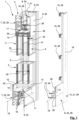
- the second profile half-shell 8 is brought into engagement with the insulating web 9. In the example shown, this is done both indirectly (via the connecting elements 28 of the connecting device 10 ) and directly, as can be seen particularly well from the upper horizontal profile section of the door leaf profile 4 in Figure 1 There you can see that the second Profile half-shell 8 is inserted into the insulating web 9 in a direction perpendicular to the sash plane 3 in such a way that the connecting elements 28 are completely immersed or retracted into groove-shaped profile sections 16 of the insulating web 9.
- the webs 26 of the second profile half-shell 8, to which the connecting elements 28 are positively connected are also retracted somewhat into the groove-shaped profile sections 16 of the insulating web 9 and in these areas are in direct contact with the insulating web 9.
- the engagement of the second profile half-shell 8 and the insulating web 9 therefore exists in the example according to Figure 1 within the meaning of the present application, both directly and indirectly.
- the engagement of the second profile half-shell 8 with the insulating web 9 is furthermore designed such that in the direction parallel to the respective profile longitudinal axes 18 of the profile parts 21, 22 of the profile half-shells 8 , no positive connection is formed, or the respective engagement is designed without positive connection. Due to the lack of positive connection in this direction, the second profile half-shell 8 and the insulating web 9 are also connected to one another without constraint within the meaning of the present application. This configuration enables movement of the respective profile parts 21, 22 relative to one another in a direction parallel to the longitudinal axis, i.e., in a direction parallel to the respective profile longitudinal axis 18.
- This frictional engagement contributes to the transfer of forces, namely in the form of frictional forces, to a certain extent in a direction perpendicular to the leaf plane 3 between the insulating strip 9 and the second profile half-shell 8. This is particularly advantageous for the assembly of the door leaf profile 4 , as it prevents unintentional "slipping" between the insulating strip 9 and the second profile half-shell 8.
- This frictional engagement can, however, be broken again without causing damage, so that the second profile half-shell 8 can be removed from the insulating strip 9 as such without causing damage in a direction perpendicular to the leaf plane 3 (as long as the adhesive bonds 20 on the edging strips 14, 15 with the outer surfaces 5, 6 of the leaf filling 2 are not effective).
- the two profile half-shells 7, 8 can be moved towards each other as required during assembly of the door leaf 1 until the edging strips 14, 15 abut the outer surfaces 5, 6 of the leaf filling 2 as described above.
- the design of the profile half-shells 7, 8 or the insulating web 9 does not predetermine a defined position in the direction perpendicular to the leaf plane 3 in which the profile half-shells 7, 8 must be located to form a properly functioning door leaf profile 4.
- the door leaf profile 4 can be individually adapted to the respective leaf filling 2 by the second profile half-shell 8 or the connecting device 10 arranged thereon is pushed into the insulating web 9 as far as the thickness 25 of the respective leaf filling 2 allows and requires.
- this offset 30 is here and preferably only 3 mm.
- Such a small offset (up to 8 mm) is referred to in the art and in the context of the present application as a "flush connection” or “virtually flush connection.”
- the profile half-shells 7, 8 are not directly or indirectly connected to one another in the direction perpendicular to the leaf plane 3 , forming a positive connection, movement of the profile half-shells 7, 8 in said direction relative to one another would essentially remain unaffected. In other words, the door leaf profile 4 would not "hold together" in the direction perpendicular to the leaf plane 3.
- the previously mentioned adhesive bond 20 is provided. Accordingly, the edging strips 14, 15 of the profile half-shells 7, 8 are each provided with an adhesive bond 20 , which comes into direct contact both with the respective edging strip 14, 15 and with the respective outer surface 5, 6 of the leaf panel 2.
- the adhesive bonds 20 each form a material bond between the leaf panel 2 and the respective profile half-shell 7, 8 .
- profile half-shells 7, 8 This causes the profile half-shells 7, 8 to no longer be able to move relative to the sash filling 2 in the direction perpendicular to the sash plane 3. Accordingly, the profile half-shells 7, 8 are effectively also fixed relative to one another in the direction perpendicular to the sash plane 3 as soon as they are bonded to the sash filling 2 using the adhesives 20. Force is therefore transmitted from one of the profile half-shells 7, 8 in the direction perpendicular to the sash plane 3 to the other profile half-shell 7, 8 in the door leaf 1 via the adhesives 20 and the sash filling 2 .
- the adhesive bonds 20 are formed by double-sided adhesive tape.
- the adhesive tapes of the adhesive bonds 20 each have a Elastomer-formed base body. This ensures that the adhesive joints 20 have a certain flexibility, which allows movement of the leaf filling 2 relative to a respective profile half-shell 7, 8, in particular in directions parallel to the leaf plane 3.
- the generated range of movement for such relative movements is typically only in the range of approximately 1 mm/m. It serves to reduce deformations of the individual components (profile half-shells 7, 8 and leaf filling 2 ) due to temperature differences on the two sides of the door leaf 1 through corresponding relative movements of the components to one another. This prevents the door leaf 1 as a whole from deforming in an undesirable manner.
- the adhesive joints 20 extend here and preferably in each case over an entire length, measured parallel to the respective profile longitudinal axis 18 , of the respectively associated edging strip 14, 15 of the respective profile part 21, 22.
- the webs 26 together with the connecting elements 28 connected thereto, engage in the groove-shaped profile sections 16 of the insulating web 9 in such a way that a relative movement of the second profile half-shell 8 to the first profile half-shell 7 or to the insulating web 9 firmly connected to the latter in a direction parallel to the leaf plane 3 and perpendicular to the respective profile longitudinal axis 18 is prevented.
- forces acting on the door leaf profile 4 in said direction can be transmitted and distributed between the two profile half-shells 7, 8. This also results in a correspondingly distributed force introduction via the adhesive joints 20 into the leaf filling 2 and vice versa.
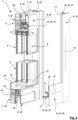
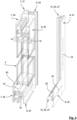
- connection device 10 which is firmly connected to the second profile half-shell 8 is, in comparison to the first embodiment according to Figure 1 While the connecting device 10 in the embodiment according to Figure 1 comprises a plurality of individual connecting elements 28 , the connecting device 10 in the embodiment according to the Figures 2 and 3 formed by a second insulating web 27.
- This second insulating web 27 comprises a plurality of elongated web parts 23, 24, wherein each of the horizontally oriented profile parts 22 of the second profile half-shell 8 is assigned a horizontally oriented web part 24 of the second insulating web 27 and each of the vertically oriented profile parts 21 of the second profile half-shell 8 is assigned a vertically oriented web part 23 of the second insulating web 27.
- the web parts 23, 24 of the second insulating web 27 each extend parallel to the respective profile longitudinal axis 18 of the respectively associated profile part 21, 22 of the second profile half-shell 8.
- the web parts 23, 24 each extend over an entire length of the respectively associated profile part 21, 22.
- the web parts 23, 24 are formed from extruded plastic profiles.
- the web parts 23, 24 of the second insulating web 27 each have two spring-shaped profile sections 17 , which are provided and configured to engage or retract into complementary groove-shaped profile sections 16 of the first insulating web 9.
- the assembly of the door leaf profile 4 proceeds analogously to the embodiment according to Figure 1 . Accordingly, during assembly, the second profile half-shell 8 , together with the connecting device 10 fixedly arranged thereon, is moved in a direction perpendicular to the leaf plane 3 towards the first profile half-shell 7 or the first insulating web 9 fixedly arranged thereon, so that the spring-shaped profile sections 17 of the connecting device 10 move into the groove-shaped profile sections 16 of the insulating web 9.
- the second profile half-shell 8 can therefore be moved towards the first profile half-shell 7 until the second profile half-shell 8 , with its edging strip 15 and the adhesive 20 interposed, strikes the corresponding edge region 13 of the outer surface 6 of the leaf filling 2.
- the door leaf profile 4 is flush or almost flush with the leaf filling 2 , as desired.
- the design of the connecting device 10 in the form of a second insulating web 27 offers the advantage that the effective distance between the two profile half-shells 7, 8 is smaller than that in Figure 1 shown embodiment can be further increased, so that the heat transfer coefficient of the door leaf profile 4 is comparatively low.
- a design of the connecting device 10 with a plurality of individual connecting elements 28 according to the embodiment in Figure 1 be beneficial.
- the second profile half-shell 8 is exclusively in direct engagement with the insulating web 9 of the door leaf profile 4.
- the second profile half-shell 8 has webs 26 extending in a direction perpendicular to the leaf plane 3 , which are intended and configured to retract into groove-shaped profile sections 16 of the insulating web 9 in a direction perpendicular to the leaf plane 3 during the assembly of the door leaf 1.
- this embodiment is the simplest of the exemplary embodiments shown here, since the door leaf profile 4 does not have a connecting device 10 that must be connected separately to the second profile half-shell 8.
- this embodiment is disadvantageous compared to the previously described ones, since the webs 26 of the second profile half-shell 8 reach comparatively close to the first profile half-shell 7 (and are thus deeply inserted into the groove-shaped profile sections 16 of the first profile half-shell 7 ), so that at least mathematically the heat transfer coefficient of the door leaf profile 4 is at a disadvantage compared to the solutions that use a connecting device 10 .
- FIG. 6 Another example is shown in Figure 6 This is similar to the embodiment according to Figure 1
- the door leaf 1 shown here comprises a connecting device 10 with block-shaped connecting elements 28, which, in contrast to the embodiment according to Figure 1 are designed.
- the connecting elements 28 are connected to an associated receptacle 32 of the profile parts 21, 22 of the second profile half-shell 8 , wherein during assembly, by screwing in a screw, a not-shown expansion element of a respective connecting element 28 located in the receptacle 32 is expanded and thus locked in the receptacle 32.
- the insulating web 9 connected to the first profile half-shell 7 here has two groove-shaped profile sections 16 , wherein the first groove-shaped profile section 16 is matched in its dimensions to the connecting elements 28 , while the second groove-shaped profile section 16 is matched in its dimensions to a web 26 of the second profile half-shell 8.
- the second profile half-shell 8 engages here both indirectly and directly with the insulating web 9. The indirect engagement takes place via the connecting elements 28 in cooperation with the first groove-shaped profile section 16 , and the direct engagement takes place via the web 26 with the second groove-shaped profile section 16.
- the door leaf 1 according to the invention can be used particularly advantageously in the form of a sliding door leaf, in particular for an automatic sliding door.
- the almost flush connection of the leaf filling 2 to the door leaf profile 4 , or vice versa is particularly advantageous in order to minimize the risk of injury during operation of the door leaf 1.
- the door leaf 1 preferably has at least one sealing contour 31 along a side of a vertical profile section of the door leaf profile 4 facing away from the leaf filling 2.
- the door leaf 1 comprises two parallel sealing contours 31 extending towards each other, which are arranged next to each other when viewed in a direction perpendicular to the sash plane 3.
- the sash filling 2 is in Figure 5 Not shown to simplify the illustration.
- the sealing contours 31 can each be formed from an extruded plastic profile and extend at least substantially over the entire height of the door leaf 1. They are arranged on the end face of the door leaf profile 4 facing away from the leaf filling 2 in such a way that they are designed to cooperate sealingly with a complementary sealing partner. This is intended, in particular, to enable an at least substantially windtight and raintight connection of the door leaf 1 to a respective component against which the door leaf 1 abuts.
- the same can have two sliding door leaves, wherein both sliding door leaves have complementarily shaped sealing contours 31 on the mutually facing end faces of the respective door leaf profile 4 of the respective door leaf 1 , so that the sealing contours 31 engage with one another in a sealing manner when the automatic sliding door is in a closed state.
Landscapes
- Engineering & Computer Science (AREA)
- Civil Engineering (AREA)
- Structural Engineering (AREA)
- Securing Of Glass Panes Or The Like (AREA)
Applications Claiming Priority (1)
| Application Number | Priority Date | Filing Date | Title |
|---|---|---|---|
| DE102023135607.0A DE102023135607A1 (de) | 2023-12-18 | 2023-12-18 | Türflügel für eine Haustür, Ladentür oder dergleichen |
Publications (1)
| Publication Number | Publication Date |
|---|---|
| EP4575166A1 true EP4575166A1 (fr) | 2025-06-25 |
Family
ID=93925596
Family Applications (1)
| Application Number | Title | Priority Date | Filing Date |
|---|---|---|---|
| EP24220938.5A Pending EP4575166A1 (fr) | 2023-12-18 | 2024-12-18 | Battant de porte, système comprenant une pluralité de battants de porte, porte coulissante automatique dotée d'au moins un battant de porte et procédé de fabrication d'un battant de porte |
Country Status (2)
| Country | Link |
|---|---|
| EP (1) | EP4575166A1 (fr) |
| DE (1) | DE102023135607A1 (fr) |
Citations (3)
| Publication number | Priority date | Publication date | Assignee | Title |
|---|---|---|---|---|
| DE3102921A1 (de) | 1980-11-18 | 1982-07-08 | Schmidlin, Hans, CH-4147 Aesch | "fenster oder tuer" |
| KR20150139351A (ko) * | 2014-06-03 | 2015-12-11 | (주)동해공영 | 단열개선형 자동출입문 |
| EP4092240A1 (fr) * | 2021-05-18 | 2022-11-23 | GPF Innovation GmbH | Nouvelle technique de collage destinée à la pose de fenêtres |
Family Cites Families (2)
| Publication number | Priority date | Publication date | Assignee | Title |
|---|---|---|---|---|
| DE1116376B (de) * | 1955-11-08 | 1961-11-02 | Eric Sigfrid Persson | Mindestens dreifach verglaster Fensterfluegel |
| US9617779B2 (en) * | 2014-03-10 | 2017-04-11 | Thomas Jesse Charlton | Modular door lite components |
-
2023
- 2023-12-18 DE DE102023135607.0A patent/DE102023135607A1/de active Pending
-
2024
- 2024-12-18 EP EP24220938.5A patent/EP4575166A1/fr active Pending
Patent Citations (3)
| Publication number | Priority date | Publication date | Assignee | Title |
|---|---|---|---|---|
| DE3102921A1 (de) | 1980-11-18 | 1982-07-08 | Schmidlin, Hans, CH-4147 Aesch | "fenster oder tuer" |
| KR20150139351A (ko) * | 2014-06-03 | 2015-12-11 | (주)동해공영 | 단열개선형 자동출입문 |
| EP4092240A1 (fr) * | 2021-05-18 | 2022-11-23 | GPF Innovation GmbH | Nouvelle technique de collage destinée à la pose de fenêtres |
Also Published As
| Publication number | Publication date |
|---|---|
| DE102023135607A1 (de) | 2025-06-18 |
Similar Documents
| Publication | Publication Date | Title |
|---|---|---|
| EP0829609B1 (fr) | Profilé composite calorifuge pour portes, fenêtres ou façades | |
| AT515184B1 (de) | Vorrichtung für das Verschließen einer Gebäudeöffnung | |
| EP1555376A1 (fr) | Profilé composite | |
| DE19605467A1 (de) | Anputzleiste für Fensterstöcke, Türstöcke oder dergleichen am Übergang zu Putz | |
| CH699766B1 (de) | Rahmenanschlussteil zur Befestigung an einem Rahmen. | |
| EP2594720B1 (fr) | Cadres de fenêtre et de porte escamotables avec différents matériaux à base de matériaux thermoplastiques pouvant être soudés | |
| LU504779B1 (de) | Verbundkonstruktion für feststehende und bewegbare flächenelemente | |
| WO2010063297A1 (fr) | Système de retenue pour vitres isolantes | |
| EP2666948B1 (fr) | Agencement de cadre pour un panneau de porte sectionnelle | |
| EP4092240A1 (fr) | Nouvelle technique de collage destinée à la pose de fenêtres | |
| DE102019213920A1 (de) | Außentür oder Fenster | |
| DE3032939A1 (de) | Rahmenprofil fuer fenster, tueren o.dgl. aus einem kunststoffhauptprofil und einem metallverblendprofil und verfahren zur herstellung von rahmen aus diesen rahmenprofilen | |
| EP2088275B1 (fr) | Profilé d'étanchéité de côtés, notamment pour profilés de cadre et installations de portes coulissantes en étant équipées | |
| DE29602315U1 (de) | Glasverbundplatte für feststehende und/oder bewegbare Scheiben im Hochbau | |
| DE19635409B4 (de) | Glastür für Brandschutzzwecke sowie Verfahren zum Herstellen einer Glastür für Brandschutzzwecke | |
| DE202011101654U1 (de) | Thermisch getrenntes Profil | |
| EP1659254B1 (fr) | Vantail de porte ou fenêtre | |
| EP4575166A1 (fr) | Battant de porte, système comprenant une pluralité de battants de porte, porte coulissante automatique dotée d'au moins un battant de porte et procédé de fabrication d'un battant de porte | |
| DE4206345C2 (de) | Verfahren und Vorrichtung zum Befestigen von Fassadenplatten | |
| EP3543450B1 (fr) | Système de profilé de porte relevable et coulissante / coulissante | |
| DE2516036A1 (de) | Waermeisoliertes aluminiumprofil fuer aussenwandkonstruktionen | |
| DE3201083A1 (de) | Abdeckvorrichtung, insbesondere fuer eine sockelfuge | |
| AT402836B (de) | Halteeinrichtung für platten, insbesondere glasplatten, in ausschnitten von bauteilen | |
| EP4345239A1 (fr) | Cadre pour border au moins une vitre et dispositif comprenant le cadre et un cadre | |
| EP3140484B1 (fr) | Profilé de liaison pour portes, fenêtres ou éléments de façade |
Legal Events
| Date | Code | Title | Description |
|---|---|---|---|
| PUAI | Public reference made under article 153(3) epc to a published international application that has entered the european phase |
Free format text: ORIGINAL CODE: 0009012 |
|
| STAA | Information on the status of an ep patent application or granted ep patent |
Free format text: STATUS: THE APPLICATION HAS BEEN PUBLISHED |
|
| AK | Designated contracting states |
Kind code of ref document: A1 Designated state(s): AL AT BE BG CH CY CZ DE DK EE ES FI FR GB GR HR HU IE IS IT LI LT LU LV MC ME MK MT NL NO PL PT RO RS SE SI SK SM TR |
|
| STAA | Information on the status of an ep patent application or granted ep patent |
Free format text: STATUS: REQUEST FOR EXAMINATION WAS MADE |
|
| 17P | Request for examination filed |
Effective date: 20250923 |