US4424930A - Carbon-based soldering and de-soldering tip and method of manufacturing same - Google Patents
Carbon-based soldering and de-soldering tip and method of manufacturing same Download PDFInfo
- Publication number
- US4424930A US4424930A US06/278,408 US27840881A US4424930A US 4424930 A US4424930 A US 4424930A US 27840881 A US27840881 A US 27840881A US 4424930 A US4424930 A US 4424930A
- Authority
- US
- United States
- Prior art keywords
- tip
- coating
- soldering
- solder
- intermediate portion
- Prior art date
- Legal status (The legal status is an assumption and is not a legal conclusion. Google has not performed a legal analysis and makes no representation as to the accuracy of the status listed.)
- Expired - Fee Related
Links
Images


Classifications
-
- B—PERFORMING OPERATIONS; TRANSPORTING
- B23—MACHINE TOOLS; METAL-WORKING NOT OTHERWISE PROVIDED FOR
- B23K—SOLDERING OR UNSOLDERING; WELDING; CLADDING OR PLATING BY SOLDERING OR WELDING; CUTTING BY APPLYING HEAT LOCALLY, e.g. FLAME CUTTING; WORKING BY LASER BEAM
- B23K3/00—Tools, devices or special appurtenances for soldering, e.g. brazing, or unsoldering, not specially adapted for particular methods
- B23K3/02—Soldering irons; Bits
- B23K3/025—Bits or tips
- B23K3/026—Removable soldering bits
-
- Y—GENERAL TAGGING OF NEW TECHNOLOGICAL DEVELOPMENTS; GENERAL TAGGING OF CROSS-SECTIONAL TECHNOLOGIES SPANNING OVER SEVERAL SECTIONS OF THE IPC; TECHNICAL SUBJECTS COVERED BY FORMER USPC CROSS-REFERENCE ART COLLECTIONS [XRACs] AND DIGESTS
- Y10—TECHNICAL SUBJECTS COVERED BY FORMER USPC
- Y10T—TECHNICAL SUBJECTS COVERED BY FORMER US CLASSIFICATION
- Y10T29/00—Metal working
- Y10T29/49—Method of mechanical manufacture
- Y10T29/4998—Combined manufacture including applying or shaping of fluent material
- Y10T29/49982—Coating
- Y10T29/49986—Subsequent to metal working
Definitions
- the present invention relates to a carbon-based soldering or de-soldering tips for use with soldering irons and de-soldering tools, respectively.
- the tip includes plated soldering surfaces. More particularly, the invention is directed to replaceable soldering and de-soldering tips which are less expensive than standard copper tips, have longer working lives, resist pitting, and eliminate or greatly reduce the problems associated with standard soldering tips.
- the invention further relates to a method for manufacturing carbon-based soldering and de-soldering tips.
- the tips are resistent to both high temperatures and corrosion and can be used with all types of soldering irons and de-soldering tools, including temperature-controlled soldering irons and de-soldering tools.
- soldering irons have soldering tips, and the majority of soldering irons are adapted to receive replaceable soldering tips. Replaceable tips are normally inserted into a tip-receiving bore of a soldering iron and are threaded or fixed in place by a set screw or similar mechanical device. It is further known that many temperature-controlled soldering irons include a sensor element extending within the iron's tip-receiving bore. The sensor element fits within a portion of a permanent or replaceable soldering iron tip.
- de-soldering tools have replaceable de-soldering tips which are normally screw-threaded to the tool. These tips include a central tubular vacuum passage through which the melted solder is drawn.
- Soldering and de-soldering tips have conventionally been formed from a copper body due, in part, to the heat conductivity of such copper bodies.
- This standard use of copper as a body of these tips has, however, presented a number of problems. Whenever copper comes into contact with commonly used solders, the solder reacts with the copper and dissolves it. Therefore, copper tips must be plated at least in the solder-wetting portion of the tips. Furthermore, the tubular vacuum passage of a de-soldering tip must be plated or otherwise protected from contact with the melted solder. If it is not, the passage becomes clogged. The plating of the copper base, however, does not completely solve the problem since the coatings wear over time and most often initially have slight imperfections and cracks. Heated solder seeps through such imperfections and worn areas and dissolves the copper base, resulting in cavities in the tip similar to tooth cavities. Thus, copper-based tips often lose their shape and effectiveness after a short period of use.
- soldering and de-soldering tips presents an additional and significant problem. Copper, when subjected to the high temperature necessary for soldering or de-soldering, quickly oxidizes. This oxidation damages a tip's surface and, more importantly, often results in a freezing of a replaceable tip to the body of the soldering iron or de-soldering tool at the interface of the tip and the tip-receiving bore. Furthermore, if a soldering iron has a temperature sensor inserted into a bore in the tip, the tip and the temperature sensor often freeze together. This freezing of parts damages the soldering iron itself and often necessitates repair or renders the iron completely unuseable.
- the oxidation tends to decrease the sensitivity of control.
- the heat sensor To measure the tip temperature accurately, it must fit snugly within the sensor hole.
- the oxidation of the copper at the sensor-tip interface decreases the heat transfer and sensitivity of the control and often chases the tip to freeze to the sensor. This freezing problem is so significant that in most commercial applications the bore receiving the sensor is oversized to eliminate or reduce the freezing. This procedure, however, decreases heat transfer and thus the sensitivity of the temperature control.
- soldering and de-soldering tips in many applications have decreased substantially in size to permit precise soldering.
- the demand for smaller soldering tips aggravates the problems presented by the pitting and oxidation of copper-based tips.
- Another object is to provide a soldering or de-soldering tip having a body which will not dissolve when contacted with solder and will not oxidize at high temperatures.
- Another object is to provide a de-soldering tip which does not require that its tubular vacuum passage be plated or lined with an additional sleeve of material.
- the invention comprises a tip for a soldering iron or a de-soldering tool comprising a carbon-based body having an attachment portion, an intermediate portion adjoining said attachment portion, and a solder-wetting portion adjoining said intermediate portion, first means coated on at least the solder-wetting portion for providing a wettable surface, and second means coated over at least the intermediate portion, but not the solder-wetting portion, for localizing the wettable working surface and impeding the upward flow of solder along said intermediate portion and toward the attachment portion.
- the invention also comprises a method of manufacturing tips for a soldering iron or a de-soldering tool comprising the steps of forming a soldering tip carbon-based body having an attachment portion, an intermediate portion adjoining said attachment portion, and a solder-wetting portion adjoining said intermediate portion, electroplating at least the intermediate portion and the solder-wetting portion with a coating of iron, electroplating at least the intermediate portion with a coating of nickel over said iron coating, electroplating at least the intermediate portion with a coating of chrome over said nickel coating, and stripping the solder-wetting portion of any nickel or chrome coatings to expose the iron coating as a wetting surface.
- FIG. 1 is a side view illustrating one embodiment of the invention.
- FIG. 2 is an enlarged cross-sectional view taken along lines 2--2 of FIG. 1.
- FIG. 3 is an enlarged cross-sectional view taken along the lines 3--3 of FIG. 1.
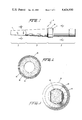
- FIG. 4 is a side view illustrating a second preferred embodiment of the invention.
- FIG. 5 is an enlarged cross-sectional view taken along the lines 5--5 of FIG. 4.
- FIG. 6 is an enlarged cross-sectional view taken along the lines 6--6 of FIG. 4.
- FIG. 7 is an enlarged cross-sectional view taken along the lines 7--7 of FIG. 4.
- FIG. 8 is a side view showing an embodiment of the invention fixed in a temperature-controlled electric soldering iron.
- FIG. 9 is a side view of a third embodiment of the invention.
- FIG. 10 is a front view of the third embodiment of the invention.
- FIG. 11 is a cross-section of the third embodiment of the invention.
- FIG. 1 is a side illustration of one embodiment of a soldering tip made according to the present invention.
- the soldering iron tip shown in FIG. 1 and designated generally as numeral 10 includes a shank or attachment portion A, an intermediate portion B adjoining the attachment portion A, and a solder-wetting portion C adjoining the intermediate portion B.
- the shank or attachment portion A is inserted into a bore in the heating element of a soldering iron, as shown generally in FIG. 8.
- the soldering tip 10 may include a ferrite iron heat sensing element or magnestat 12 fixed to the distal end of the attachment portion A. When the soldering tip 10 is inserted in a soldering iron the magnestat contacts with a temperature sensing device in the soldering iron.
- the attachment portion A is preferentially cylindrical in shape, and the tip 10 tapers generally along the intermediate portion B and the solder-wetting portion C.
- the working end 14 of the tip 10 can be formed in a shape most beneficial to the particular application for which the tip is designed.
- the tip can include a shoulder 16 with bevel edges 18. This shoulder acts as a stop to properly position the tip 10 within a soldering iron and also serves as a barrier to stop any possible upward flow of solder from the solder-wetting portion C toward the attachment portion A.
- the solder tip has an integral carbon-based body 20.
- the carbon-based body can be made from pure carbon, carbon graphite, pyrolytic carbon or silicon carbide.
- the applicant has found that each of these above carbon-based materials provides an acceptable soldering or de-soldering tip base with sufficient heat conductivity. It is believed that other carbon-based materials may be likewise acceptable.
- carbon graphite is the preferred body material for most commercial applications.
- Carbon graphite has sufficient heat conductivity and is low in cost.
- Carbon graphite has a thermal conductivity which approximates 60% of the normal thermal conductivity of pure copper and costs 1/3 to 1/5 as much.
- other carbon-based materials may be more appropriate.
- pyrolytic carbon can be fashioned to provide a much better thermal conductivity than copper.
- the cost of pyrolytic carbon is 3-5 times as much as copper.
- the carbon-based body provides several advantages over copper and other known base materials for soldering and de-soldering tips. Carbon does not dissolve when placed in contact with solders. Furthermore, the carbon does not oxidize or react with other elements at high temperatures and does not have a liquid state. Furthermore, carbon-based materials are easily fabricated on standard machine tools, often at lesser costs than copper. Finally, as will be explained below, the carbon-based body readily accepts platings of metals during a plating process.
- the soldering tip includes a coating of iron 22 formed over the entire exterior body of the tip.
- a coating of nickel plating 24 is formed over the iron coating 22 along the intermediate portion B and the attachment portion A, but not along the solder-wetting portion C.
- a coating 26 of chromium is formed over the nickel plating 24 along the intermediate portion B and the attachment portion A, but not along the solder-wetting portion C.
- the iron coating 22 provides a wettable surface in the working area 14 of the tip.
- the nickel-chrome coating localizes the wettable working surface so that precision soldering can be achieved.
- the nickel-chrome coating also impedes the upward flow of solder along the intermediate portion B and toward the attachment portion A. Without the coating, solder would flow to the point where the soldering tip and soldering iron meet and might bond the tip and iron together.
- the attachment portion includes the exterior coatings of iron, nickel and chrome.
- the resultant carbon-based tip is not subject to the degree of oxidation that a copper-based tip is, since the carbon-based material will not oxidize. As will be described below, it is possible to further reduce the oxidation problems by stripping all coatings from the attachment portion A so that only uncoated, bare carbon-based material interfaces with the solderng iron.
- FIG. 4 A second embodiment of a soldering tip made according to the invention is shown in FIG. 4, FIG. 5, FIG. 6 , and FIG. 7, wherein like numbers are used to refer to like parts.
- the soldering tip 10 shown in FIG. 4 includes an elongated bore 19 formed in the attachment portion A and sized to receive snugly a temperature-sensing element of a soldering iron.
- the soldering tip in FIG. 4 is similar to the tip in FIG. 1 and includes a carbon-based body 20, an iron coating 22, a nickel coating 24, and a chrome coating 26.
- the tip includes a thin coating of dull nickel 21 formed between the carbon-based body 20 and the iron coating 22 along the intermediate portion B and the solder-wetting portion C.
- the thin coating of dull nickel is necessary only when the tips are coated by a barrel plating process, rather than a rack plating process.
- the primary distinction between the embodiment shown in FIG. 1 and FIG. 4 is that the attachment portion A does not include any metal coatings in the finished product. Furthermore, there is no coating on the inner surface of the elongated bore 19.
- This embodiment is the present preferred embodiment of a soldering tip made in accordance with the invention and prevents any possible oxidation or freezing of the attachment portion A to the soldering iron or to the temperature-sensing element of the soldering iron.
- the coating of iron has a thickness in the range of 6 to 10 mils
- the outer coating of nickel has a thickness in the range of 0.05 to 1 mils
- the coating of chrome has a thickness in the range of 0.5 to 1 mils. If an inner coating of dull nickel is used, that coating is approximately 0.5 mils thick.
- FIG. 8 illustrates an embodiment of the present invention attached to a temperature-controlled soldering iron with a temperature-sensing element.
- the soldering iron includes a general body portion 30 with a tip-receiving bore 32. Within the tip-receiving bore 32 is a sensor element 34 for sensing the temperature of the soldering tip.
- the sensor 34 is snugly received by the elongated bore 19.
- a tip nut 36 or a similar mechanical device is used to fix or lock the tip to the soldering iron.
- FIGS. 9 through 11 illustrate an embodiment of a de-soldering tip 40 made according to the invention.
- the de-soldering tip 40 includes an attachment portion A, an intermediate portion B adjoining the attachment portion A, and a solder-wetting portion C adjoining the intermediate portion B.
- the tip 40 includes a central tubular vacuum passage 42, and the attachment portion A includes mounting threads 44.
- the de-soldering tip 40 is threaded onto a de-soldering tool, which is well-known in the art.
- the tip is heated and then brought into contact with solder which the operator desires to remove from a circuit.
- a vacuum source is connected to the vacuum passage 42 so that as the solder is melted, the melted solder is drawn off through the tube 42.
- the de-soldering tip 40 shown in FIG. 11 has an integral carbon-based body 46 and includes a coating of iron 48 formed over the entire exterior body of the tip.
- a coating of nickel plating 50 is formed over the iron coating 48 along the intermediate portion B and the attachment portion A, but not along the solder-wetting portion C.
- a coating 52 of chromium is formed over the nickel plating 50 along the intermediate portion B and the attachment portion A, but not along the solder-wetting portion C.
- the coatings are the same coatings used on the soldering tips previously described and serve the same purposes. If it is desired to coat the de-soldering tip 46 by a barrel coating process, an additional dull nickel coating would first be plated directly on the carbon-based body by a rack plating process, and the additional coatings would be made by a barrel coating process.
- the wall of the tubular vacuum passage 42 is uncoated, bare carbon.
- the melted solder will not adhere to this carbon, and therefore it is unnecessary to plate the passage or place a stainless steel tube in the passage.
- the soldering and de-soldering tip of the present invention provides several benefits not found in commercial copper soldering and de-soldering tips.
- the carbon-based body is not prone to oxidation or dissolving. Because of these characteristics, the carbon-based body will not cavitate or oxidize at points of discontinuity or wear in the metal coatings.
- the tip of the present invention therefore, eliminates the problems of pitting, heat transfer loss by oxidation, and freezing by oxidation.
- the present invention also provides a longer lasting tip at a lower cost.
- the carbon-based tip can be coated more quickly than copper, and the porous material of the carbon-based tip absorbs impurities in the plating baths and results in a more defect-free plating job.
- a tip is machined to the desired shape by a typical machining element such as a lathe or turning machine. It has been found that the preferred carbon-based materials are easily adaptable to such machining. Due to the production of dust during machining, special dust collecting equipment should be used.
- the desired coatings are electroplated on the base by a rack or barrel coating process, or a desired combination of both. Both of these coating processes ae well-known in the art. The preferred process depends upon the availability of coating machinery, the number of tips to be produced, and the economics of operation.
- the tips are to be coated by a rack coating process, the tips are first electroplated with a coating of iron through the use of a common iron plating bath, such as iron Fluoroborate. Next, a coating of nickel is electroplated over the iron coating, and finally a coating of chrome is electroplated over the nickel coating.
- Plating baths for electroplating nickel and chrome are well-known.
- the nickel and chrome coatings are stripped from the solder-wetting portion of the tip to expose the iron coating as the wetting surface. If desired, the nickel and chrome coatings, can also be stripped from the attachment portion of the tips.
- the barrel coating process may be more economical than a rack coating process, particularly if the tips are produced on a large scale. If tips are to be made by the barrel coating process, it is preferable first to place a thin dull coating of nickel over the base by a rack coating process. This thin coating strengthens the pointed end of the tip so it will not break during the barrel coating process. The remaining steps of electroplating iron, nickel and chrome can be made in a barrel coating process. Then, at least the solder-wetting portion is stripped of any nickel or chrome coatings to expose the iron coating as a wetting surface.
Landscapes
- Engineering & Computer Science (AREA)
- Mechanical Engineering (AREA)
- Electric Connection Of Electric Components To Printed Circuits (AREA)
- Connections Effected By Soldering, Adhesion, Or Permanent Deformation (AREA)
Priority Applications (8)
| Application Number | Priority Date | Filing Date | Title |
|---|---|---|---|
| US06/278,408 US4424930A (en) | 1981-06-29 | 1981-06-29 | Carbon-based soldering and de-soldering tip and method of manufacturing same |
| DE8282105728T DE3273169D1 (en) | 1981-06-29 | 1982-06-28 | Carbon-based soldering and de-soldering tip and method of manufacturing same |
| EP82105728A EP0068484B1 (de) | 1981-06-29 | 1982-06-28 | Löt- und Entlötspitze auf Kohlenstoffbasis und Verfahren zu ihrer Herstellung |
| CA000406163A CA1188160A (en) | 1981-06-29 | 1982-06-28 | Carbon-based soldering and de-soldering tip and method of manufacturing same |
| JP57110076A JPS586773A (ja) | 1981-06-29 | 1982-06-28 | ハンダ付け及びハンダ除去用こて先き、及びその製造方法 |
| AU85396/82A AU549404B2 (en) | 1981-06-29 | 1982-06-28 | Soldering tip |
| HU822112A HU187460B (en) | 1981-06-29 | 1982-06-29 | Soldering head of carbon base and method for producing same |
| CA000472586A CA1200439A (en) | 1981-06-29 | 1985-01-22 | Carbon-based soldering and de-soldering tip and method of manufacturing same |
Applications Claiming Priority (1)
| Application Number | Priority Date | Filing Date | Title |
|---|---|---|---|
| US06/278,408 US4424930A (en) | 1981-06-29 | 1981-06-29 | Carbon-based soldering and de-soldering tip and method of manufacturing same |
Publications (1)
| Publication Number | Publication Date |
|---|---|
| US4424930A true US4424930A (en) | 1984-01-10 |
Family
ID=23064863
Family Applications (1)
| Application Number | Title | Priority Date | Filing Date |
|---|---|---|---|
| US06/278,408 Expired - Fee Related US4424930A (en) | 1981-06-29 | 1981-06-29 | Carbon-based soldering and de-soldering tip and method of manufacturing same |
Country Status (7)
| Country | Link |
|---|---|
| US (1) | US4424930A (de) |
| EP (1) | EP0068484B1 (de) |
| JP (1) | JPS586773A (de) |
| AU (1) | AU549404B2 (de) |
| CA (1) | CA1188160A (de) |
| DE (1) | DE3273169D1 (de) |
| HU (1) | HU187460B (de) |
Cited By (21)
| Publication number | Priority date | Publication date | Assignee | Title |
|---|---|---|---|---|
| US4560101A (en) * | 1983-06-16 | 1985-12-24 | Cooper Industries, Inc. | Self-locking, removeable tapered tips for soldering and de-soldering tools |
| US4974768A (en) * | 1988-02-22 | 1990-12-04 | Mitsui Engineering & Shipbuilding Co., Ltd. | Soldering iron tip |
| US4997121A (en) * | 1989-06-29 | 1991-03-05 | Hakko Corporation | Nozzle of solder suction device |
| US5476580A (en) * | 1993-05-17 | 1995-12-19 | Electrochemicals Inc. | Processes for preparing a non-conductive substrate for electroplating |
| WO1996005014A1 (en) * | 1994-08-17 | 1996-02-22 | WELLER, Emily, I. | Soldering iron tip made from a copper/iron alloy composite |
| US5690805A (en) * | 1993-05-17 | 1997-11-25 | Electrochemicals Inc. | Direct metallization process |
| US5725807A (en) * | 1993-05-17 | 1998-03-10 | Electrochemicals Inc. | Carbon containing composition for electroplating |
| US6171468B1 (en) | 1993-05-17 | 2001-01-09 | Electrochemicals Inc. | Direct metallization process |
| US6303181B1 (en) | 1993-05-17 | 2001-10-16 | Electrochemicals Inc. | Direct metallization process employing a cationic conditioner and a binder |
| EP1043105A3 (de) * | 1999-04-09 | 2002-06-05 | Ersa GmbH | Werkzeug zur Übertragung von Wärme von einer Wärmequelle auf ein zu bearbeitendes Werkstück und Verfahren zu dessen Herstellung |
| US6710259B2 (en) | 1993-05-17 | 2004-03-23 | Electrochemicals, Inc. | Printed wiring boards and methods for making them |
| CN100430173C (zh) * | 2001-12-14 | 2008-11-05 | 亥伯龙创新公司 | 无绳烙铁 |
| US20090140028A1 (en) * | 2007-11-30 | 2009-06-04 | Nordson Corporation | Soldering tip, soldering iron, and soldering system |
| JP4634003B2 (ja) * | 2000-08-01 | 2011-02-16 | 白光株式会社 | コテ先チップ及び電気ハンダゴテ |
| US20120248598A1 (en) * | 2011-03-31 | 2012-10-04 | International Business Machines Corporation | Semiconductor bonding apparatus |
| US20160175958A1 (en) * | 2014-12-19 | 2016-06-23 | Hakko Corporation | Desoldering Tool Nozzle And Method of Manufacturing the Nozzle |
| USD859109S1 (en) * | 2019-03-11 | 2019-09-10 | Pro-Iroda Industries, Inc. | Soldering bit |
| US10751822B2 (en) * | 2018-09-25 | 2020-08-25 | Ok International, Inc. | Smart soldering iron tip and method of authenticating same |
| US10751823B2 (en) * | 2018-09-25 | 2020-08-25 | Ok International, Inc. | Smart soldering iron tip and method of authenticating same |
| CN112139626A (zh) * | 2020-08-27 | 2020-12-29 | 深圳市鹏创鑫自动化设备有限公司 | 一种小间距焊锡洛铁头 |
| US20210252621A1 (en) * | 2017-08-24 | 2021-08-19 | Micron Technology, Inc. | Solder removal from semiconductor devices |
Families Citing this family (5)
| Publication number | Priority date | Publication date | Assignee | Title |
|---|---|---|---|---|
| DE3641873C1 (de) * | 1986-12-08 | 1987-08-20 | Sachs Ersa Kg | Loetspitze |
| JPH0723105Y2 (ja) * | 1990-05-01 | 1995-05-31 | 株式会社宝山工具製作所 | 半田こて先用ビット |
| DE20010044U1 (de) * | 2000-06-07 | 2000-09-07 | Bach, Friedrich-Wilhelm, Prof. Dr.-Ing., 30916 Isernhagen | Einhand-Lötgerät mit integriertem Lotdepot und dosierbarem Lotangebot |
| JP7137237B2 (ja) * | 2020-09-09 | 2022-09-14 | 株式会社アポロ技研 | ヒーターチップユニット |
| JP7137235B2 (ja) * | 2020-09-09 | 2022-09-14 | 株式会社アポロ技研 | ヒーターチップ、および、ヒーターチップユニット |
Citations (15)
| Publication number | Priority date | Publication date | Assignee | Title |
|---|---|---|---|---|
| US750239A (en) | 1904-01-19 | A coepoeation | ||
| US1880940A (en) | 1931-04-21 | 1932-10-04 | Enninga Dirk | Tool |
| DE684612C (de) | 1936-06-25 | 1939-12-01 | Siemens & Halske Akt Ges | Loetkolben mit einer an einem waermezufuehrenden Koerper angebrachten Loetfinne oder Loetspitze aus porigem Metall |
| GB547303A (en) | 1941-07-01 | 1942-08-21 | Western Electric Co | Improvements in or relating to soldering irons |
| US2747074A (en) | 1949-05-24 | 1956-05-22 | Gen Electric | Electric soldering iron |
| US2951927A (en) | 1958-08-21 | 1960-09-06 | Carl E Weller | Electric soldering iron |
| US3109231A (en) | 1960-06-20 | 1963-11-05 | Hexacon Electric Company | Method of producing soldering tips for electric soldering irons |
| US3125055A (en) | 1964-03-17 | Soldering tip | ||
| US3245599A (en) | 1960-06-20 | 1966-04-12 | Hexacon Electric Company | Soldering tip for electric soldering irons |
| US3287541A (en) | 1964-07-13 | 1966-11-22 | Weller Electric Corp | Temperature controlled soldering iron |
| US3315350A (en) | 1963-12-27 | 1967-04-25 | Plato Products Inc | Method of manufacturing replaceable soldering iron tips |
| US3410472A (en) | 1967-02-06 | 1968-11-12 | Avco Corp | Electrically isolated copper soldering iron tip |
| US3646577A (en) | 1970-03-30 | 1972-02-29 | Ncr Co | Temperature-controlled soldering tool |
| US3917148A (en) | 1973-10-19 | 1975-11-04 | Technical Devices Inc | Welding tip |
| US4049506A (en) | 1974-09-03 | 1977-09-20 | Tribotech | Method for coating bonding tools and product |
Family Cites Families (8)
| Publication number | Priority date | Publication date | Assignee | Title |
|---|---|---|---|---|
| US2102032A (en) * | 1936-01-13 | 1937-12-14 | William R Richardson | Soldering iron |
| CH225403A (de) * | 1942-05-22 | 1943-01-31 | Chapalay Elsa | Elektrische Lötvorrichtung. |
| CH233232A (de) * | 1943-03-20 | 1944-07-15 | Transformatoren En Apparatenfa | Elektrische Lötvorrichtung. |
| FR1390452A (fr) * | 1964-01-31 | 1965-02-26 | Skandinaviska Telekompaniet Ab | Procédé de fabrication d'une panne de fer à souder et panne produite par ce procédé |
| GB1114396A (en) * | 1967-03-15 | 1968-05-22 | Plato Products Inc | Method of manufacturing replaceable soldering-iron tips |
| US3662152A (en) * | 1971-03-05 | 1972-05-09 | Cooper Ind Inc | Thermomagnetic soldering tip assembly and method |
| US3963897A (en) * | 1971-09-17 | 1976-06-15 | Stanley Electric Co., Ltd. | Electrically heated solder removing bit |
| DE2646705C2 (de) * | 1976-10-13 | 1978-11-09 | Ersa Ernst Sachs Kg Gmbh & Co, 6980 Wertheim | Temperaturgeregelter Lötkolben |
-
1981
- 1981-06-29 US US06/278,408 patent/US4424930A/en not_active Expired - Fee Related
-
1982
- 1982-06-28 AU AU85396/82A patent/AU549404B2/en not_active Ceased
- 1982-06-28 DE DE8282105728T patent/DE3273169D1/de not_active Expired
- 1982-06-28 JP JP57110076A patent/JPS586773A/ja active Granted
- 1982-06-28 CA CA000406163A patent/CA1188160A/en not_active Expired
- 1982-06-28 EP EP82105728A patent/EP0068484B1/de not_active Expired
- 1982-06-29 HU HU822112A patent/HU187460B/hu not_active IP Right Cessation
Patent Citations (15)
| Publication number | Priority date | Publication date | Assignee | Title |
|---|---|---|---|---|
| US3125055A (en) | 1964-03-17 | Soldering tip | ||
| US750239A (en) | 1904-01-19 | A coepoeation | ||
| US1880940A (en) | 1931-04-21 | 1932-10-04 | Enninga Dirk | Tool |
| DE684612C (de) | 1936-06-25 | 1939-12-01 | Siemens & Halske Akt Ges | Loetkolben mit einer an einem waermezufuehrenden Koerper angebrachten Loetfinne oder Loetspitze aus porigem Metall |
| GB547303A (en) | 1941-07-01 | 1942-08-21 | Western Electric Co | Improvements in or relating to soldering irons |
| US2747074A (en) | 1949-05-24 | 1956-05-22 | Gen Electric | Electric soldering iron |
| US2951927A (en) | 1958-08-21 | 1960-09-06 | Carl E Weller | Electric soldering iron |
| US3109231A (en) | 1960-06-20 | 1963-11-05 | Hexacon Electric Company | Method of producing soldering tips for electric soldering irons |
| US3245599A (en) | 1960-06-20 | 1966-04-12 | Hexacon Electric Company | Soldering tip for electric soldering irons |
| US3315350A (en) | 1963-12-27 | 1967-04-25 | Plato Products Inc | Method of manufacturing replaceable soldering iron tips |
| US3287541A (en) | 1964-07-13 | 1966-11-22 | Weller Electric Corp | Temperature controlled soldering iron |
| US3410472A (en) | 1967-02-06 | 1968-11-12 | Avco Corp | Electrically isolated copper soldering iron tip |
| US3646577A (en) | 1970-03-30 | 1972-02-29 | Ncr Co | Temperature-controlled soldering tool |
| US3917148A (en) | 1973-10-19 | 1975-11-04 | Technical Devices Inc | Welding tip |
| US4049506A (en) | 1974-09-03 | 1977-09-20 | Tribotech | Method for coating bonding tools and product |
Non-Patent Citations (1)
| Title |
|---|
| Abstract of Application Ser. No. 82,457 Published in Official Gazette of the U.S. Patent Office, vol. 637, p. 1576, Aug. 1950. |
Cited By (29)
| Publication number | Priority date | Publication date | Assignee | Title |
|---|---|---|---|---|
| US4560101A (en) * | 1983-06-16 | 1985-12-24 | Cooper Industries, Inc. | Self-locking, removeable tapered tips for soldering and de-soldering tools |
| US4974768A (en) * | 1988-02-22 | 1990-12-04 | Mitsui Engineering & Shipbuilding Co., Ltd. | Soldering iron tip |
| US4997121A (en) * | 1989-06-29 | 1991-03-05 | Hakko Corporation | Nozzle of solder suction device |
| US7186923B2 (en) | 1993-05-17 | 2007-03-06 | Electrochemicals, Inc. | Printed wiring boards and methods for making them |
| US6303181B1 (en) | 1993-05-17 | 2001-10-16 | Electrochemicals Inc. | Direct metallization process employing a cationic conditioner and a binder |
| US5476580A (en) * | 1993-05-17 | 1995-12-19 | Electrochemicals Inc. | Processes for preparing a non-conductive substrate for electroplating |
| US20040084321A1 (en) * | 1993-05-17 | 2004-05-06 | Thorn Charles Edwin | Printed wiring boards and methods for making them |
| US5690805A (en) * | 1993-05-17 | 1997-11-25 | Electrochemicals Inc. | Direct metallization process |
| US5725807A (en) * | 1993-05-17 | 1998-03-10 | Electrochemicals Inc. | Carbon containing composition for electroplating |
| US6171468B1 (en) | 1993-05-17 | 2001-01-09 | Electrochemicals Inc. | Direct metallization process |
| US6710259B2 (en) | 1993-05-17 | 2004-03-23 | Electrochemicals, Inc. | Printed wiring boards and methods for making them |
| US5579533A (en) * | 1994-08-17 | 1996-11-26 | Donald Fegley | Method of making a soldering iron tip from a copper/iron alloy composite |
| US5553767A (en) * | 1994-08-17 | 1996-09-10 | Donald Fegley | Soldering iron tip made from a copper/iron alloy composite |
| WO1996005014A1 (en) * | 1994-08-17 | 1996-02-22 | WELLER, Emily, I. | Soldering iron tip made from a copper/iron alloy composite |
| EP1043105A3 (de) * | 1999-04-09 | 2002-06-05 | Ersa GmbH | Werkzeug zur Übertragung von Wärme von einer Wärmequelle auf ein zu bearbeitendes Werkstück und Verfahren zu dessen Herstellung |
| JP4634003B2 (ja) * | 2000-08-01 | 2011-02-16 | 白光株式会社 | コテ先チップ及び電気ハンダゴテ |
| CN100430173C (zh) * | 2001-12-14 | 2008-11-05 | 亥伯龙创新公司 | 无绳烙铁 |
| US20090140028A1 (en) * | 2007-11-30 | 2009-06-04 | Nordson Corporation | Soldering tip, soldering iron, and soldering system |
| US7699208B2 (en) * | 2007-11-30 | 2010-04-20 | Nordson Corporation | Soldering tip, soldering iron, and soldering system |
| US20120248598A1 (en) * | 2011-03-31 | 2012-10-04 | International Business Machines Corporation | Semiconductor bonding apparatus |
| US20160175958A1 (en) * | 2014-12-19 | 2016-06-23 | Hakko Corporation | Desoldering Tool Nozzle And Method of Manufacturing the Nozzle |
| US9776271B2 (en) * | 2014-12-19 | 2017-10-03 | Hakko Corporation | Desoldering tool nozzle and method of manufacturing the nozzle |
| US20210252621A1 (en) * | 2017-08-24 | 2021-08-19 | Micron Technology, Inc. | Solder removal from semiconductor devices |
| US11745281B2 (en) * | 2017-08-24 | 2023-09-05 | Micron Technology, Inc. | Solder removal from semiconductor devices |
| US10751822B2 (en) * | 2018-09-25 | 2020-08-25 | Ok International, Inc. | Smart soldering iron tip and method of authenticating same |
| US10751823B2 (en) * | 2018-09-25 | 2020-08-25 | Ok International, Inc. | Smart soldering iron tip and method of authenticating same |
| EP4549070A3 (de) * | 2018-09-25 | 2025-09-03 | OK International, Inc. | Intelligente lötspitze und verfahren zur authentifizierung davon |
| USD859109S1 (en) * | 2019-03-11 | 2019-09-10 | Pro-Iroda Industries, Inc. | Soldering bit |
| CN112139626A (zh) * | 2020-08-27 | 2020-12-29 | 深圳市鹏创鑫自动化设备有限公司 | 一种小间距焊锡洛铁头 |
Also Published As
| Publication number | Publication date |
|---|---|
| AU8539682A (en) | 1983-01-06 |
| HU187460B (en) | 1986-01-28 |
| EP0068484A2 (de) | 1983-01-05 |
| AU549404B2 (en) | 1986-01-23 |
| CA1188160A (en) | 1985-06-04 |
| JPS586773A (ja) | 1983-01-14 |
| EP0068484B1 (de) | 1986-09-10 |
| JPH0250827B2 (de) | 1990-11-05 |
| DE3273169D1 (en) | 1986-10-16 |
| EP0068484A3 (en) | 1983-11-16 |
Similar Documents
| Publication | Publication Date | Title |
|---|---|---|
| US4424930A (en) | Carbon-based soldering and de-soldering tip and method of manufacturing same | |
| EP0132569B1 (de) | Selbstverriegelnde abnehmbare konische Spitzen für Löt- und Auslötwerkzeuge | |
| KR100449568B1 (ko) | 용접용콘택트팁 | |
| US4997121A (en) | Nozzle of solder suction device | |
| EP2065114A1 (de) | Lötspitze mit einer nichtbenetzbaren Kontaktschicht ; Löteisen mit einer solchen Lötspitze ; Lötsystem mit einem solchen Löteisen | |
| EP0001921B1 (de) | Verzinntes Kupfergeflecht zur Lötentfernung und Verfahren zu dessen Herstellung | |
| KR19990036716A (ko) | 가열용 팁 및 그 제조 방법 | |
| US3109231A (en) | Method of producing soldering tips for electric soldering irons | |
| CA1200439A (en) | Carbon-based soldering and de-soldering tip and method of manufacturing same | |
| JP3753859B2 (ja) | ハンダ鏝及び鏝先部材 | |
| KR910004525B1 (ko) | 기계적 도금방법 | |
| JPH1157996A (ja) | こて先部材および半田ごて | |
| JPS61286060A (ja) | ハンダ付け用治具部材 | |
| KR960013709B1 (ko) | 전기 납땜 인두의 가열팁 | |
| US3578942A (en) | Welding electrode assembly | |
| US20060169744A1 (en) | Soldering tip with wear-and corrosion resistant coating | |
| JPH0231115A (ja) | 溶融アルミニウム金属及び合金の湯面検知用センサー | |
| KR860008820A (ko) | 속이빈 작업도구를 만드는데 관한방법 | |
| JP2540416Y2 (ja) | 半田ごて | |
| JPH0417974A (ja) | 半田用チップおよびその製造方法 | |
| JPH0670961U (ja) | はんだごて用こて先 | |
| JPH07144271A (ja) | 半田ごて | |
| JPH0455062A (ja) | プラズマアーク加工用電極およびその製造方法 | |
| JPH0723105Y2 (ja) | 半田こて先用ビット | |
| US3427140A (en) | Tip of ruthenium metal for soldering iron |
Legal Events
| Date | Code | Title | Description |
|---|---|---|---|
| AS | Assignment |
Owner name: COOPER INDUSTRIES, INC., TWO HOUSTON CENTER, SUITE Free format text: ASSIGNMENT OF ASSIGNORS INTEREST.;ASSIGNOR:WILHELMSON, JACK L.;REEL/FRAME:003927/0021 Effective date: 19810623 |
|
| MAFP | Maintenance fee payment |
Free format text: PAYMENT OF MAINTENANCE FEE, 4TH YEAR, PL 96-517 (ORIGINAL EVENT CODE: M170); ENTITY STATUS OF PATENT OWNER: LARGE ENTITY Year of fee payment: 4 |
|
| FEPP | Fee payment procedure |
Free format text: PAYOR NUMBER ASSIGNED (ORIGINAL EVENT CODE: ASPN); ENTITY STATUS OF PATENT OWNER: LARGE ENTITY |
|
| MAFP | Maintenance fee payment |
Free format text: PAYMENT OF MAINTENANCE FEE, 8TH YEAR, PL 96-517 (ORIGINAL EVENT CODE: M171); ENTITY STATUS OF PATENT OWNER: LARGE ENTITY Year of fee payment: 8 |
|
| FEPP | Fee payment procedure |
Free format text: MAINTENANCE FEE REMINDER MAILED (ORIGINAL EVENT CODE: REM.); ENTITY STATUS OF PATENT OWNER: LARGE ENTITY |
|
| LAPS | Lapse for failure to pay maintenance fees | ||
| FP | Lapsed due to failure to pay maintenance fee |
Effective date: 19960110 |
|
| STCH | Information on status: patent discontinuation |
Free format text: PATENT EXPIRED DUE TO NONPAYMENT OF MAINTENANCE FEES UNDER 37 CFR 1.362 |