US4543705A - Axial-lead component sequencing and inserting apparatus - Google Patents
Axial-lead component sequencing and inserting apparatus Download PDFInfo
- Publication number
- US4543705A US4543705A US06/642,650 US64265084A US4543705A US 4543705 A US4543705 A US 4543705A US 64265084 A US64265084 A US 64265084A US 4543705 A US4543705 A US 4543705A
- Authority
- US
- United States
- Prior art keywords
- component
- components
- improvement
- leads
- conveying
- Prior art date
- Legal status (The legal status is an assumption and is not a legal conclusion. Google has not performed a legal analysis and makes no representation as to the accuracy of the status listed.)
- Expired - Fee Related
Links
Images




Classifications
-
- H—ELECTRICITY
- H05—ELECTRIC TECHNIQUES NOT OTHERWISE PROVIDED FOR
- H05K—PRINTED CIRCUITS; CASINGS OR CONSTRUCTIONAL DETAILS OF ELECTRIC APPARATUS; MANUFACTURE OF ASSEMBLAGES OF ELECTRICAL COMPONENTS
- H05K13/00—Apparatus or processes specially adapted for manufacturing or adjusting assemblages of electric components
- H05K13/04—Mounting of components, e.g. of leadless components
- H05K13/0417—Feeding with belts or tapes
- H05K13/0426—Feeding with belts or tapes for components being oppositely extending terminal leads
-
- Y—GENERAL TAGGING OF NEW TECHNOLOGICAL DEVELOPMENTS; GENERAL TAGGING OF CROSS-SECTIONAL TECHNOLOGIES SPANNING OVER SEVERAL SECTIONS OF THE IPC; TECHNICAL SUBJECTS COVERED BY FORMER USPC CROSS-REFERENCE ART COLLECTIONS [XRACs] AND DIGESTS
- Y10—TECHNICAL SUBJECTS COVERED BY FORMER USPC
- Y10T—TECHNICAL SUBJECTS COVERED BY FORMER US CLASSIFICATION
- Y10T29/00—Metal working
- Y10T29/51—Plural diverse manufacturing apparatus including means for metal shaping or assembling
- Y10T29/5136—Separate tool stations for selective or successive operation on work
- Y10T29/5137—Separate tool stations for selective or successive operation on work including assembling or disassembling station
- Y10T29/5142—Separate tool stations for selective or successive operation on work including assembling or disassembling station and means to sever work from supply
-
- Y—GENERAL TAGGING OF NEW TECHNOLOGICAL DEVELOPMENTS; GENERAL TAGGING OF CROSS-SECTIONAL TECHNOLOGIES SPANNING OVER SEVERAL SECTIONS OF THE IPC; TECHNICAL SUBJECTS COVERED BY FORMER USPC CROSS-REFERENCE ART COLLECTIONS [XRACs] AND DIGESTS
- Y10—TECHNICAL SUBJECTS COVERED BY FORMER USPC
- Y10T—TECHNICAL SUBJECTS COVERED BY FORMER US CLASSIFICATION
- Y10T29/00—Metal working
- Y10T29/51—Plural diverse manufacturing apparatus including means for metal shaping or assembling
- Y10T29/5147—Plural diverse manufacturing apparatus including means for metal shaping or assembling including composite tool
- Y10T29/5148—Plural diverse manufacturing apparatus including means for metal shaping or assembling including composite tool including severing means
- Y10T29/515—Plural diverse manufacturing apparatus including means for metal shaping or assembling including composite tool including severing means to trim electric component
-
- Y—GENERAL TAGGING OF NEW TECHNOLOGICAL DEVELOPMENTS; GENERAL TAGGING OF CROSS-SECTIONAL TECHNOLOGIES SPANNING OVER SEVERAL SECTIONS OF THE IPC; TECHNICAL SUBJECTS COVERED BY FORMER USPC CROSS-REFERENCE ART COLLECTIONS [XRACs] AND DIGESTS
- Y10—TECHNICAL SUBJECTS COVERED BY FORMER USPC
- Y10T—TECHNICAL SUBJECTS COVERED BY FORMER US CLASSIFICATION
- Y10T29/00—Metal working
- Y10T29/51—Plural diverse manufacturing apparatus including means for metal shaping or assembling
- Y10T29/5193—Electrical connector or terminal
-
- Y—GENERAL TAGGING OF NEW TECHNOLOGICAL DEVELOPMENTS; GENERAL TAGGING OF CROSS-SECTIONAL TECHNOLOGIES SPANNING OVER SEVERAL SECTIONS OF THE IPC; TECHNICAL SUBJECTS COVERED BY FORMER USPC CROSS-REFERENCE ART COLLECTIONS [XRACs] AND DIGESTS
- Y10—TECHNICAL SUBJECTS COVERED BY FORMER USPC
- Y10T—TECHNICAL SUBJECTS COVERED BY FORMER US CLASSIFICATION
- Y10T29/00—Metal working
- Y10T29/53—Means to assemble or disassemble
- Y10T29/5313—Means to assemble electrical device
- Y10T29/5317—Laminated device
Definitions
- the present invention relates generally to an axiallead component insertion machine incorporating an endless conveyor for feeding axial lead components in a predetermined sequence from plural supply dispensers to an insertion head which trims, forms, and inserts the component leads into holes of a circuit board.
- film or tape mounted axial lead components have been fed to an insertion head which is adapted in sequence to: sever the leads of a presented component in order to separate such component from the film or a pair of spaced carrier tapes; bend the severed leads at right angles to the axis of the separated component; and finally drive the bent leads into preformed apertures provided in a circuit board disposed below the insertion head.
- U.S. Pat. No. 3,783,488 and U.S. Pat. No. Re. 27,968 are exemplary of such prior art and the disclosures of these patents are incorporated into this application by reference.
- U.S. Pat. No. 3,455,493 discloses the feeding of axial lead components to an insertion head from a sequencer via an endless conveyor which supports the components for transport by cradling the leads, with components of different values being supplied to the head in a preselected sequence on said conveyor.
- Two prior art centering devices are cross-referenced above and disclose lead forming, trimming, and inserting tooling of an insert head centered about a midplane such that tape fed components may be generally centered on the midplane, by opening and closing the tooling relative to the midplane, either while still attached to the feed tapes or after separation therefrom by lead trimming.
- the clips are electrically insulative in order that on-line verifying of the electrical functioning thereof may be performed.
- repair functions comprise replacement, centering, and testing of missing components, defective components, and misinserted components.
- the present invention involves a method and apparatus for feeding axial lead components directly from a sequencer to an insertion head while eliminating direct supplying of components to the insert head via a predetermined inventory such as reeled tapes or films having components attached thereto in a predetermined sequence.
- a predetermined inventory such as reeled tapes or films having components attached thereto in a predetermined sequence.
- an endless chain conveyor carries the components to the insert head from the sequencer in chain clips which positively retain the lead of the components while allowing centering of the bodies and electrical function testing of the components positively retained therein.
- the conveyor is capable of carrying several series of sequenced components, and the overall apparatus is changeable without manual intervention for bypassing the insert head with one or more components of a series without insert processing thereof, and changing the individually and programmably controlled dispenser heads of the sequencer.
- Such an arrangement provides for quick and flexible variation of the next sequenced series of components to be fed to the insert head.
- a particular portion of the conveyor in the area of the insert tooling is shiftable forwardly and reversely. Such shifting allows retraction of the inside formers of the insert tooling without interference with conveyor-carried components at the insert station.
- the insert head of the instant invention is provided with a housing or door assembly covering a portion of the conveyor at the front or operator accessible portion of the insertion machine.
- This door assembly includes a verifier for the on-line testing of electrical functioning of each component and a centering mechanism for centering the bodies of the components about a mid plane while the leads thereof are retained in the clip carriers of the conveyor. Still further, when a component is missing or is defective and must be replaced, the centering arms of the door assembly are also operable to load a replacement component into a particular position of the conveyor, upon opening of the clip carriers of that position by an opener mechanism also mounted upon this door assembly.
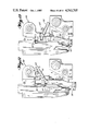
- FIG. 1 is a front elevation of the insertion head, with a phantom line illustration of the door assembly in the open position.
- FIG. 2 is a left side elevation of the device of FIG. 1.
- FIG. 3 is a front elevation of the door assembly in the closed position.
- FIG. 4 is a left side elevation, partially in cross-section, of the door assembly of FIG. 3.
- FIG. 5 is an elevation, as generally viewed in the direction of arrows 5--5 of FIG. 4, with the verifier assembly removed for clarity of illustrations of the loading and centering arms.
- FIG. 6 is a partial, detailed view of the cam for opening the centering and loading arms.
- FIG. 7 is a left side elevation of the centering mechanism separate from FIG. 4.
- FIG. 8 is an elevation of one centering arm, as generally viewed in the direction of arrows 8--8 of FIG. 7.
- FIG. 9 is a left side elevation of the verifier assembly separated from FIG. 4.
- FIG. 10 is an elevation of the verifier assembly, as viewed by the components being tested.
- FIG. 11 is an exploded, isometric view of the insert head tooling assembly.
- FIGS. 12 and 13 are elevations of one half of the split tooling assembly, as viewed from the midplane, in order to illustrate the action of the retractable inside former.
- FIG. 14 is a side elevation illustrating details of the transfer of components from the sequencer to the inserter.
- FIG. 15 is a left side schematic, generally indicating stations of operation relative to the feed path of the conveyor chain at the front of the insertion head.
- FIG. 16 is a front elevation, partially broken away, of a carrier clip.
- FIG. 17 is a left side elevation, partially broken away, of the clip of FIG. 16.
- FIG. 18 is a front elevation of the roll for opening the chain clips.
- FIGS. 19 and 19a are a schematic of the timing belts and conveyors of the complete system, illustrating their interactions together and with the sequencer and inserter.
- FIGS. 20 and 20a are an elevational view illustrating the shift actuating assembly.
- the split tooling insertion head assembly of FIG. 1 has a basic configuration similar to that of the above cross-referenced U.S. Pat. No. Re. 27,968 and is adapted to receive axial lead electrical components, via the supply and feed system illustrated in FIGS. 19, 20 and 14, for processing and mounting thereof onto a printed circuit board.
- a sequencer 10 has a plurality of dispenser heads 12 to drop individual components onto an endless chain conveyor 14 and provide a series of presequenced components thereon.
- An example of a sequencer useful in this invention is given in the above cross-referenced U.S. Pat. No. 3,455,493.
- the series of presequenced components is transferred from conveyor chain 14 via transfer wheel 18 to another conveyor chain 20 which is located on the right hand side of FIG. 19, as indicated generally at 80.
- the provision of separate conveyor chains 14 and 20 and transfer wheel 18, along with other features of this invention, allows a supply of components to be fed at a generally constant rate to the insert head via conveyors 14 and 20, while also allowing that the front or right hand portion of conveyor 20 is shiftable forwardly and reversely relative to the constant rate of feed of the left hand portion of conveyor 20.
- timing belt 76 is drivingly coupled with the right hand portion of chain 20 via timing belt sprocket 78 mounted to the same shaft as chain sprocket 84 (best seen in FIG. 1).
- Timing belt 76 is drivingly coupled to timing belt 50 via timing belt sprockets 54 and 74 sharing a common rotation shaft.
- sprockets 52, 54, and 55 are fixed to a main frame, and sprockets 58 are shiftable relative to the main frame via a shift actuator assembly 56.
- sprocket 52 is drivingly coupled with chains 14 and 20 and transfer wheel 18 via other timing belts, any one of which may conceivably be directly or indirectly coupled to a main driving motor (not shown).
- Shift actuator assembly 56 is best seen in FIG. 20 and comprises double sprockets 58 which are vertically displaceable as a unit by actuation of one or both of shift cylinders 62, 64.
- the piston rod of each cylinder 62, 64 is pivotally attached to a lever 66 which, in turn, is pivotally attached to 68 to double sprocket assembly 58, and an adjustable stop 60 provide limits of travel of each end of lever 66.
- shift cylinder 62 or 64 the corresponding end of lever 66 is raised from the normal operating position of FIG.
- double sprocket assembly 58 is raised sufficiently that a half-step counterclockwise component of displacement is superimposed upon the normal clockwise rotation of timing belt 50.
- double sprocket assembly 58 is raised sufficiently to superimpose a full step of counterclockwise displacement upon clockwise rotating timing belt 50. Accordingly, either a half step or a full step backward component of movement is imparted to the normal forward movement of timing belt 50.
- Timing belt sprockets 54 and 70 are drivingly coupled to the same jack shaft 74, such that the triangular path of travel of timing belt 76 will have the same displacement component imparted thereto as does timing belt 50 upon actuation of shift assembly 56.
- belt sprocket 78 of timing belt 76 is drivingly supported by the same rotatable shaft as is chain sprocket 84, about which conveyor 20 is passed.
- Spring biased chain tensioners 42 are positioned between two sets of fixed sprockets 43, 45 with the chain played thereabout, as illustrated in FIG. 19, such that the selected half step or full step reversed component of movement imparted to timing belt 76 is imparted to that portion of conveyor chain 20 which runs around the insert head 80.
- the arrangement of chain tensioners 42 and fixed sprockets 43, 45 allows movement of only that portion of conveyor chain 20 which is to the right of sprockets 43 as viewed in FIG. 19.
- an additional component of forward or reverse movement may be imparted to the "insert head portion" of chain 20 according to the forward or reverse displacement component imparted to the normal forward movement of timing belt 76.
- a forward component of displacement superimposable on normal movement of the timing belts and, hence, on the insert head portion of chain 20 it should be noted that such a forward component is realized, for instance, upon returning one or both shift cylinders 62, 64 to the normal extended position.
- each half of the split tooling assembly 88 normally has: movable and fixed cutting blades 98 and 99 for trimming the ends of axial lead components; outside formers 94 for cooperating with inside formers 90; and forming the leads for insertion into holes of a printed circuit board; and kickout arms 92 supporting inside formers 90 such that the insider formers 90 are pivoted clear of the path of reciprocation of a driver 96 which drives the leads into circuit board holes.
- the instant invention comprises a slide way 97 within which kickout arm 92 may reciprocate after clearing inside former 90 from the path of travel of driver 96.
- Kickout arm 92 is caused to raise via a linked connection with pivotal lever 91, and to lower via the bias of spring 95.
- lever 91 is actuated by engagement with a rod 85 attached to link 89 which, in turn, is pivotally attached to link 86 for reciprocation thereof by cylinder 93.
- sequencer chain 14 is provided with V-notches into which the leads of components are cradled, and transfer wheel 18 has cooperating notches for lifting the components out of the notches of chain 14 and depositing them into clip carriers 22 of inserter chain 20.
- a clip carrier 22 is shown in detail in FIGS. 16 and 17 and comprises an electrically insulative body 24 with a V-notch 26 for receiving each component lead and a pivotal latch 28 having a lead engaging portion 30 for retaining the leads in V-notch 26.
- Compression spring 36 biases latch 28 about pivot point 38 to the position illustrated in FIG. 17.
- Portion 32 of latch member 28 is engageable by a clip opening roller 44 of FIG. 14 (shown in detail in FIG.
- the instant invention is provided with meas to detect missing, defective, and misinserted components and to load replacement components into the respective chain clips 22 corresponding thereto and to center and verify electrical functioning of each of the replacement components. Provision is also made for testing and centering of each and every component prior to insertion thereof. Such functions are provided by the door assembly 100 of FIGS. 3-5 (also shown in phantom lines in FIGS. 1 and 2).
- Door assembly 100 is attached to insert head 80 via hinge 102, with fine vertical adjustment of door assembly 100 relative to insert head 80 being provided by adjustable bushings 103 and cooperating nuts 104 (FIG. 3).
- Handle 180 is provided with an electrical interlock switch 182 which must be depressed by the operator in order to acutate cylinder 184 and release a locking pin 186 for opening of door 100.
- a loading and centering housing 110 is mounted for pivoting about axis 115 through door assembly 100, with pivotal support and a lateral adjustment of housing 110 be provided by pins 112. Lateral adjustment and locking of pins 112 is accomplished through means of a set screw and locking nut arrangement 113.
- a pair of cooperating loading and centering arms 116 are pivotally supported by housing 110 via pivot pins 119, with springs 118 biasing lead receiving ends 117 toward midplane 81. The extent to which arms 116 may close upon midplane 81 is determined by engagement of the inner surfaces thereof with cam 120 which is shiftable in the direction of the longitudinal axis of shaft 122.
- Shaft 122 is caused to reciprocate along the longitudinal axis thereof via connection to arm 132 which is pivotally connected at 134 and actuated by extension and retraction of cylinder 130, as will be appreciated by reference to FIG. 4.
- cam shaft 122 is connected to an adjustment mechanism 129 through a universal joint 124, with tension springs 128 removing "play" due to machine tolerances.
- the extent to which shaft 122 and cam 120 are retractable (generally to the right as viewed in FIG. 4) is adjustably determined by a cam stop 126, best seen in FIGS. 5 and 6.
- the positioning of cam stop 126 determines the extent to which arms 116 will be spread apart, by engagement with cam 120, so that the device is adjustable for receiving component bodies of various lengths between arms 116.
- actuation of cylinder 130 will cause pivoting of housing 110 until the upper portion thereof engages with an adjustable stop 114.
- housing 110 With arms 116 spread apart, facilitates loading of an electrical component into carrier clip 22 of chain conveyor 20.
- a clip opening piston and cylinder arrangement 140 is provided which, upon firing of the cylinder, will extend the piston to engage portions 34 of chain clip latches 28 and open the chain clips 22 for reception of the leads of a component from slots 117 of each arm 116.
- a verifier support yoke 150 is also pivotal about axis 115 via support bushings 172 on pins 112, with lateral adjustment of yoke 150 provided by adjustment screw 170 (FIG. 5).
- a verifier assembly normally attached to yoke 150 has been removed from FIG. 5 in order to properly illustrate the earlier described loading and centering arms 116.
- Yoke 150 is held in the position of FIG. 4 by retracted cylinder 152. Upon release of cylinder 152, compression springs 151 causes yoke 150 to pivot about axis 115.
- L-shaped arms 154 are attached to yoke 150 and are adjustable laterally thereof according to the body lengths of the components being tested.
- Each verifier contact assembly 160 comprising an electrically insulative block 162 supporting primary verifier contact 164 and secondary verifier contact 166, which contacts are electrically attachable by any well-known means to a component tester such as the one described in U.S. Pat. No. 4,050,017. Support of the verifier assembly on door assembly 100 is provided by L-shaped bracket 156 and pivot pin 158.
- Primary contact 164 is normally positioned to contact the component leads during feeding thereof, while secondary contacts 166 are for selective subsequent tests when needed.
- a component detection system comprises a reflector 174 mounted on door assembly 100 and a bifurcated fiber optic bundle transmitter and receiver 176 opposite reflector 174 with conveyor chain 20 therebetween, such that absence of a component from a carrier clip 22 would not provide the normal interruption of the transmitter/receiver expected for each chain clip.
- conveyor chains 14 and 20 are incremented stepwise while V-notches of conveyor 14 are loaded by dispenser heads 12 of sequencer 10 according to a controller such as a programmed computer, after which the series of sequenced components are transferred by notches of rotary transfer wheel 18 to clips 22 of insert conveyor 20.
- the presequenced series of components are thus fed to the insert head 80, while the various incremental steps of movement of the conveyors are counted by the controller in order to ascertain where a first and last component of each sequence is located along the path of travel.
- a PART DETECT routine is performed in concert with incremental stepping of the conveyor 20 so as to detect whether or not a particular chain clip 22 of conveyor 20 contains a component. If absence of a component is detected, then the program is flagged for subsequent corrective action at processing station N-1. Having incremented the conveyor clip 22 to processing station N-3, a VERIFY I routine is performed by primary contacts 164 of the verifier assembly being in contact with each lead of a component and testing electrical functioning of the component. If the component tested is bad, then chain clip 22 holding it is flagged for subsequent retesting at processing station N-1. In the present prototype, no processing is performed at station N-2. At station N-1, various options are available as follows:
- latch opening cylinders 140 are fired to open latches 28 of the clip 22 and allow reception of the replacement component into conveyor clip 22 from loading arms 116.
- latches 28 Upon relaxing of cylinders 140, latches 28 retain the leads of the replacement component and arms 116 center the body of the component relative to midplane 81 through actuation of cylinder 130.
- the component is again tested by secondary contacts 166 of the verifier. If necessary, such a sequence is repeated until a replacement component tests "good" and the conveyor chain may be incremented to the next station.
- conveyor chain 20 is incremented one half-step rearwardly (to N-1/2) as earlier described, the inside former 90 is retracted, chain 20 is incremented another half-step backward, the operator is notified to open door assembly 100 and remove the misinserted component from the printed circuit board or chain clip, and the above-described replacement of a component is performed.
- processing stations N-1 and N various adjustments to the insertion tooling are performed for each component. For instance, the printed circuit board is repositioned under the insert head for reception of a new component, the insert tooling horizontal span is adjusted according to the span between the holes of the circuit board into which the component leads are to be inserted, the clinch assembly is adjusted in span to correspond to that of the insert tooling span, and the depth is adjusted to which the driver of the insert head will insert the leads into the holes (for instance, according to the component body diameters).
- the leads of the component are trimmed, formed, and inserted into the holes of the circuit board for clinching to the underside thereof, and proper insertion and clinching of the leads is detected at this time.
- a replacement routine is performed upon a misinsertion of a lead.
Landscapes
- Engineering & Computer Science (AREA)
- Manufacturing & Machinery (AREA)
- Microelectronics & Electronic Packaging (AREA)
- Supply And Installment Of Electrical Components (AREA)
- Coupling Device And Connection With Printed Circuit (AREA)
- Replacement Of Web Rolls (AREA)
- Connecting Device With Holders (AREA)
- Saccharide Compounds (AREA)
- Investigating Or Analyzing Materials By The Use Of Magnetic Means (AREA)
Priority Applications (6)
| Application Number | Priority Date | Filing Date | Title |
|---|---|---|---|
| US06/642,650 US4543705A (en) | 1984-08-20 | 1984-08-20 | Axial-lead component sequencing and inserting apparatus |
| CA000488639A CA1248489A (en) | 1984-08-20 | 1985-08-13 | Axial-lead component sequencing and inserting apparatus |
| JP60181144A JPS6190836A (ja) | 1984-08-20 | 1985-08-20 | 軸方向リ−ド部品順次配列・插入装置 |
| EP85305929A EP0175491B1 (en) | 1984-08-20 | 1985-08-20 | Axial-lead component sequencing and inserting apparatus |
| AT85305929T ATE63417T1 (de) | 1984-08-20 | 1985-08-20 | Vorrichtung zur anordnung und zur einsetzung von bauelementen mit axialen zuleitungen. |
| DE8585305929T DE3582771D1 (de) | 1984-08-20 | 1985-08-20 | Vorrichtung zur anordnung und zur einsetzung von bauelementen mit axialen zuleitungen. |
Applications Claiming Priority (1)
| Application Number | Priority Date | Filing Date | Title |
|---|---|---|---|
| US06/642,650 US4543705A (en) | 1984-08-20 | 1984-08-20 | Axial-lead component sequencing and inserting apparatus |
Publications (1)
| Publication Number | Publication Date |
|---|---|
| US4543705A true US4543705A (en) | 1985-10-01 |
Family
ID=24577460
Family Applications (1)
| Application Number | Title | Priority Date | Filing Date |
|---|---|---|---|
| US06/642,650 Expired - Fee Related US4543705A (en) | 1984-08-20 | 1984-08-20 | Axial-lead component sequencing and inserting apparatus |
Country Status (6)
| Country | Link |
|---|---|
| US (1) | US4543705A (ja) |
| EP (1) | EP0175491B1 (ja) |
| JP (1) | JPS6190836A (ja) |
| AT (1) | ATE63417T1 (ja) |
| CA (1) | CA1248489A (ja) |
| DE (1) | DE3582771D1 (ja) |
Cited By (4)
| Publication number | Priority date | Publication date | Assignee | Title |
|---|---|---|---|---|
| US4744799A (en) * | 1986-06-06 | 1988-05-17 | Usm Corporation | Combined sequencer and insertion machine |
| US5867893A (en) * | 1996-01-05 | 1999-02-09 | Tdk Corporation Of America | Clinch assembly lift mechanism |
| CN110268816A (zh) * | 2017-02-14 | 2019-09-20 | 株式会社富士 | 测定装置、测定方法 |
| CN112045381A (zh) * | 2020-07-31 | 2020-12-08 | 南京阿兹曼电子科技有限公司 | 一种电子零部件制造用圆盘送扣载具及使用方法 |
Families Citing this family (3)
| Publication number | Priority date | Publication date | Assignee | Title |
|---|---|---|---|---|
| US4733587A (en) * | 1986-06-06 | 1988-03-29 | Usm Corporation | Mechanism for body centering and lead trimming |
| US4768285A (en) * | 1986-06-06 | 1988-09-06 | Usm Corporation | Repair station for component insertion device |
| JPS6367796A (ja) * | 1986-09-09 | 1988-03-26 | 池上通信機株式会社 | チツプ部品の自動装着装置 |
Citations (8)
| Publication number | Priority date | Publication date | Assignee | Title |
|---|---|---|---|---|
| US27968A (en) * | 1860-04-24 | Carpenter s clamp | ||
| US3455493A (en) * | 1967-02-27 | 1969-07-15 | Universal Instruments Corp | Component sequencing and insertion apparatus |
| US3539086A (en) * | 1968-08-26 | 1970-11-10 | Universal Instruments Corp | Multi size variable center electronic component insertion machine |
| US3783488A (en) * | 1972-07-05 | 1974-01-08 | Universal Instruments Corp | Film mounted electronic component insertion machine |
| USRE27968E (en) | 1973-07-19 | 1974-04-09 | Multisize variable center electronic component insertion machine | |
| US4417683A (en) * | 1981-11-09 | 1983-11-29 | Universal Instruments Corporation | Centering device for electrical components |
| US4470182A (en) * | 1982-07-01 | 1984-09-11 | Universal Instruments Corporation | Method and apparatus for centering electrical components |
| US4507862A (en) * | 1983-02-28 | 1985-04-02 | Universal Instruments Corporation | Method and apparatus for high speed transfer and insertion of electrical components |
Family Cites Families (1)
| Publication number | Priority date | Publication date | Assignee | Title |
|---|---|---|---|---|
| US3193085A (en) * | 1962-03-29 | 1965-07-06 | Western Electric Co | Apparatus for conveying components |
-
1984
- 1984-08-20 US US06/642,650 patent/US4543705A/en not_active Expired - Fee Related
-
1985
- 1985-08-13 CA CA000488639A patent/CA1248489A/en not_active Expired
- 1985-08-20 EP EP85305929A patent/EP0175491B1/en not_active Expired - Lifetime
- 1985-08-20 AT AT85305929T patent/ATE63417T1/de not_active IP Right Cessation
- 1985-08-20 DE DE8585305929T patent/DE3582771D1/de not_active Expired - Lifetime
- 1985-08-20 JP JP60181144A patent/JPS6190836A/ja active Pending
Patent Citations (8)
| Publication number | Priority date | Publication date | Assignee | Title |
|---|---|---|---|---|
| US27968A (en) * | 1860-04-24 | Carpenter s clamp | ||
| US3455493A (en) * | 1967-02-27 | 1969-07-15 | Universal Instruments Corp | Component sequencing and insertion apparatus |
| US3539086A (en) * | 1968-08-26 | 1970-11-10 | Universal Instruments Corp | Multi size variable center electronic component insertion machine |
| US3783488A (en) * | 1972-07-05 | 1974-01-08 | Universal Instruments Corp | Film mounted electronic component insertion machine |
| USRE27968E (en) | 1973-07-19 | 1974-04-09 | Multisize variable center electronic component insertion machine | |
| US4417683A (en) * | 1981-11-09 | 1983-11-29 | Universal Instruments Corporation | Centering device for electrical components |
| US4470182A (en) * | 1982-07-01 | 1984-09-11 | Universal Instruments Corporation | Method and apparatus for centering electrical components |
| US4507862A (en) * | 1983-02-28 | 1985-04-02 | Universal Instruments Corporation | Method and apparatus for high speed transfer and insertion of electrical components |
Cited By (6)
| Publication number | Priority date | Publication date | Assignee | Title |
|---|---|---|---|---|
| US4744799A (en) * | 1986-06-06 | 1988-05-17 | Usm Corporation | Combined sequencer and insertion machine |
| US5867893A (en) * | 1996-01-05 | 1999-02-09 | Tdk Corporation Of America | Clinch assembly lift mechanism |
| CN110268816A (zh) * | 2017-02-14 | 2019-09-20 | 株式会社富士 | 测定装置、测定方法 |
| CN110268816B (zh) * | 2017-02-14 | 2021-03-16 | 株式会社富士 | 测定装置、测定方法 |
| CN112045381A (zh) * | 2020-07-31 | 2020-12-08 | 南京阿兹曼电子科技有限公司 | 一种电子零部件制造用圆盘送扣载具及使用方法 |
| CN112045381B (zh) * | 2020-07-31 | 2021-08-24 | 南京阿兹曼电子科技有限公司 | 一种电子零部件制造用圆盘送扣载具及使用方法 |
Also Published As
| Publication number | Publication date |
|---|---|
| DE3582771D1 (de) | 1991-06-13 |
| CA1248489A (en) | 1989-01-10 |
| EP0175491A3 (en) | 1987-11-25 |
| ATE63417T1 (de) | 1991-05-15 |
| EP0175491B1 (en) | 1991-05-08 |
| JPS6190836A (ja) | 1986-05-09 |
| EP0175491A2 (en) | 1986-03-26 |
Similar Documents
| Publication | Publication Date | Title |
|---|---|---|
| US4768285A (en) | Repair station for component insertion device | |
| US4713880A (en) | Lead making machine | |
| US4205433A (en) | Electric part insertion method and apparatus | |
| CN108971013B (zh) | 一种保险丝测试设备 | |
| US4543705A (en) | Axial-lead component sequencing and inserting apparatus | |
| JPS6314519B2 (ja) | ||
| CA1086251A (en) | Component sequence verifier | |
| US5007160A (en) | Apparatus for press-installing wires | |
| US4441386A (en) | Wire cutter and stripper apparatus | |
| US4744799A (en) | Combined sequencer and insertion machine | |
| EP0121626B1 (en) | Method and apparatus for straightening and aligning leads and testing electrical functioning of components | |
| US4733587A (en) | Mechanism for body centering and lead trimming | |
| JPS60120600A (ja) | 插入装置 | |
| US4382322A (en) | Automated welding systems and methods | |
| US6042323A (en) | Wire harness handling and storage system | |
| US4510806A (en) | Gauging method and apparatus for components having leads | |
| US4043094A (en) | Method and apparatus for processing taped components | |
| JP3568799B2 (ja) | 識別装置及び識別方法 | |
| CN215554479U (zh) | 供料装置及变压器测试包装机 | |
| JPH03257897A (ja) | 部品マウント装置 | |
| JPS62173041A (ja) | 線材切断装置 | |
| JPH02250618A (ja) | 電線の端末処理状態検査装置における移送経路調整方法 | |
| JPS5932889B2 (ja) | コンデンサ素子加工装置 | |
| JPH0361032A (ja) | タイヤ構成材料の供給方法及びその装置 | |
| JPS62171190A (ja) | 被覆線材插入装置 |
Legal Events
| Date | Code | Title | Description |
|---|---|---|---|
| AS | Assignment |
Owner name: UNIVERSAL INSTRUMENTS CORPORATION, BINGHAMTON, NY Free format text: ASSIGNMENT OF ASSIGNORS INTEREST.;ASSIGNORS:PORTERFIELD, RICHARD;SOTH, HENRY J.;BIESECKER, DOUGLAS A.;REEL/FRAME:004303/0011 Effective date: 19840814 |
|
| FEPP | Fee payment procedure |
Free format text: PAYOR NUMBER ASSIGNED (ORIGINAL EVENT CODE: ASPN); ENTITY STATUS OF PATENT OWNER: LARGE ENTITY |
|
| FPAY | Fee payment |
Year of fee payment: 4 |
|
| AS | Assignment |
Owner name: DELAWARE CAPITAL FORMATION, INC., A DE CORP., DELA Free format text: ASSIGNMENT OF ASSIGNORS INTEREST.;ASSIGNOR:UNIVERSAL INSTRUMENTS CORPORATION, A DE CORP.;REEL/FRAME:006021/0159 Effective date: 19920210 |
|
| LAPS | Lapse for failure to pay maintenance fees | ||
| FP | Lapsed due to failure to pay maintenance fee |
Effective date: 19931003 |
|
| STCH | Information on status: patent discontinuation |
Free format text: PATENT EXPIRED DUE TO NONPAYMENT OF MAINTENANCE FEES UNDER 37 CFR 1.362 |