US5075894A - Telephone message forwarding apparatus - Google Patents
Telephone message forwarding apparatus Download PDFInfo
- Publication number
- US5075894A US5075894A US07/114,452 US11445287A US5075894A US 5075894 A US5075894 A US 5075894A US 11445287 A US11445287 A US 11445287A US 5075894 A US5075894 A US 5075894A
- Authority
- US
- United States
- Prior art keywords
- message
- telephone set
- telephone
- destination
- reproducing
- Prior art date
- Legal status (The legal status is an assumption and is not a legal conclusion. Google has not performed a legal analysis and makes no representation as to the accuracy of the status listed.)
- Expired - Fee Related
Links
Images



Classifications
-
- H—ELECTRICITY
- H04—ELECTRIC COMMUNICATION TECHNIQUE
- H04M—TELEPHONIC COMMUNICATION
- H04M1/00—Substation equipment, e.g. for use by subscribers
- H04M1/26—Devices for calling a subscriber
-
- H—ELECTRICITY
- H04—ELECTRIC COMMUNICATION TECHNIQUE
- H04M—TELEPHONIC COMMUNICATION
- H04M3/00—Automatic or semi-automatic exchanges
- H04M3/42—Systems providing special services or facilities to subscribers
- H04M3/46—Arrangements for calling a number of substations in a predetermined sequence until an answer is obtained
-
- H—ELECTRICITY
- H04—ELECTRIC COMMUNICATION TECHNIQUE
- H04M—TELEPHONIC COMMUNICATION
- H04M1/00—Substation equipment, e.g. for use by subscribers
- H04M1/64—Automatic arrangements for answering calls; Automatic arrangements for recording messages for absent subscribers; Arrangements for recording conversations
- H04M1/65—Recording arrangements for recording a message from the calling party
- H04M1/658—Means for redirecting recorded messages to other extensions or equipment
Definitions
- the present invention relates to a telephone set capable of transferring a recorded message to other telephone sets.
- the types of destination automatic telephone answering apparatuses utilizable for this purpose are limited. This is because an automatic telephone answering apparatus of a certain type may not accept the message as an incoming message and hence will not record it.
- the message recorded in the recording/reproducing unit is reproduced and sent to a destination telephone set so that a called party can listen to the message, the message must be reproduced after a remote control signal or a mode number for a remote operation is supplied from the destination telephone set so as to keep the privacy of the message.
- the called party must have an oscillator for the remote control signal or be able to input the mode number for each call using the ten keys of a push-button telephone.
- a telephone set for connection to the line of a telephone system and for automatically transferring a message from the telephone set to a destination telephone set
- the telephone set comprises recording and reproducing means for recording and reproducing a message
- memory means for storing a telephone number of the destination telephone set to which said message recorded in said recording and reproducing means is to be automatically transferred
- automatic dialing means for automatically dialing the desitnation telephone set using said telephone number stored in said memory means
- detecting means for monitoring for a first predetermined time interval for signals sent from said destination telephone set through the telephone lines in response to dialing by said automatic dialing means
- message transfer means for reproducing said message recorded in said recording and reproducing means and sending said message to said destination telephone set through said telephone lines when no voice signal is continuously detected for a second predetermined time interval by said detecting means, wherein the first predetermined time interval exceeds and is inclusive of the second predetermined time interval.
- FIG. 1 is a block diagram of an embodiment of the present invention
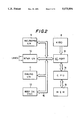
- FIG. 2 is a block diagram of an embodiment of an internal circuit
- FIGS. 3A and 3B are a flow chart of a CPU.
- FIG. 1 shows a case wherein a telephone set 1 according to the present invention sequentially and automatically transfers a common message to a plurality of telephone sets, i.e., three telephone sets 2, 3, and 4.
- the telephone set 4 has an automatic telephone answering apparatus 5, and the other telephone sets 2 and 3 are normal telephone sets without an automatic telephone answering function.
- the telephone sets 1 to 4 can communicate with each other through a telephone central office 6.
- the telephone set 1 has a handset 7 and a keyboard 8 including ten keys and operation buttons such as a message transfer start button.
- FIG. 2 is a block diagram of an internal circuit of the telephone set 1, in which the telephone set 1 includes the keyboard 8, a recording/reproducing unit 9, a network unit 10, a dialing unit 11, a beep tone oscillator 12, an I/O port 13, a CPU 14, and a digital memory 15.
- the units 9, 10, 11, and 12 are interconnected by a bus 16 to the I/O port 13, which is connected directly to the keyboard 8 and the CPU 14.
- the CPU 14 is directly connected to the digital memory 15.
- a tape recorder which uses a magnetic tape or a solid-state memory is used as the recording/reproducing unit 9.
- the telephone set 1 may have an automatic telephone answering function.
- the recording/reproducing unit 9 performs normal automatic recording, i.e., records/reproduces an outgoing message to a calling party and records/reproduces an incoming message therefrom.
- the network unit 10 is connected to telephone lines (LINES), and then the telephone number of the telephone set 2 is read out first from the memory 15.
- the dialing unit 11 automatically dials the number of the telephone set 2.
- the telephone set 1 is set in a voice detection mode for detecting the presence or absence of a voice signal sent from the telephone set 2 through the telephone lines. Therefore, the ring back tones are detected.
- signal tones i.e., beep tones are sent from a beep tone oscillator 12 to the telephone lines through the network unit 10, e.g., once a second.
- beep tones send information to the telephone set 2 representing that "a message is to be transferred from the telephone set 1 to the telephone set 2".
- the recording/reproducing unit 9 is set by the CPU 14 to be in a reproducing mode to reproduce a message to be transferred and sends it to the telephone set 2 through the network unit 10 and the telephone lines.
- the reproduced message is transferred several times, e.g., twice so that the person at the message transfer destination can completely listen to and understand the mssage.
- the silent interval is detected when the person at the message transfer destination keeps silent for four seconds.
- the signal tones i.e., the beep tones are generated from the telephone set 1 in this silent interval. Therefore, even if the person at the message transfer destination keeps silent for four seconds or more, the silent interval is not detected when these signal tones are erroneously detected as a voice signal from the telephone set 2 by the telephone set 1.
- the detection of the silent interval by the telephone set 1 is interrupted once a second, every time the beep tone is generated from the telephone set 1, so that the beep tones are not erroneously detected by the telephone set 1.
- the presence or absence of a voice signal between the respective beep tones is detected by the telephone set 1 and if any voice signal is not detected in four sequential detection periods, the telephone set 1 determines that a silent interval has been detected.
- the message transfer operation may be automatically performed with respect to the telephone set 2 again several times, e.g., in one or two hours after this interruption. Alternatively, after this interruption dialing to the telephone set 3 may commence immediately to perform the message transfer operation thereto.
- an automatic telephone answering apparatus 5 answers the call.
- a normal automatic telephone answering apparatus receives an incoming message from a telephone set, it engages the telephone lines, reproduces an outgoing message prerecorded in a magnetic tape or a solid-state memory, and informs the calling party that any incoming message will be automatically recorded "at the sound of the beep.”
- a signal tone i.e., a beep tone is sent to the calling party to inform the calling party that "you may record an incoming message"
- the automatic telephone answering apparatus 5 is set in a recording mode for recording the incoming message from the calling party.
- an incoming message from the calling party is recorded in the magnetic tape or the solid-state memory.
- an already recorded portion of the magnetic tape is wound up at a high speed before the apparatus sends a beep tone to the calling party, and then the apparatus is set in a recording mode. During this winding up at the high speed, signal tones such as chime tones are sent to the calling party.
- the automatic telephone answering apparatus 5 is set in the recording mode for recording the incoming message from the calling party. In this time, the automatic telephone answering apparatus 5 does not send any tone to the calling party, i.e., is set in the silent state. If this silent state (recording mode) continues for more than four seconds, the telephone set 1 determines that the message may be transferred to the automatic telephone answering apparatus 5, as in the step (H).
- the common message to be transferred can be sequentially transferred from the telephone set 1 to the telephone sets 2, 3, and 4.
- the message to be transferred can be recorded as an incoming message by the automatic telephone answering apparatus 5.
- the telephone set 1 determines whether the message may be transferred, by detecting a silent interval for a predetermined time interval, e.g., four seconds. Therefore, the message can be transferred to the normal telephone sets 2, 3, and 4 regardless of the type of the automatic telephone answering apparatus 5.
- the message is not transferred. Therefore, the message is not likely to be heard by a person other than the intended recipient.
- the number of the destination telephone sets 2, 3, and 4 may be arbitrarily increased or decreased.
- a message transfer code may be determined between a plurality of destinations, and the message may be transferred after this code is sent.
- the types of destination telephone sets and the destination automatic telephone answering apparatuses are limited. In this embodiment, since a silent interval of a predetermined time, e.g., four seconds is detected, the message can be transferred to any telephone set and any automatic telephone answering apparatus.
- the signal tones i.e., the beep tones are sent before the message is transferred.
- the detection of the silent interval by the telephone set 1 is interrupted every time the beep tone is generated. Therefore, the silent interval can be detected more reliably.
- recording of the message to be transferred, input of the telephone numbers of the destination telephone sets, manipulation of the message transfer start button, and the like are directly manipulated at the telephone set 1.
- the telephone set 1 may be accessed by a telephone set located at a remote place where a user is present, and a remote control signal or a message to be transferred may be sent by the user upon manipulation of the keys of a special transmitter or the telephone set located at the remote place, e.g. telephone set 2, thereby controlling the telephone set 1 from the remote place where the user is present to execute the operation of steps (A) and (B). That is, the user can execute the message transfer operation even if he or she is not near the telephone set 1.
- a remote control signal or a message to be transferred may be sent by the user upon manipulation of the keys of a special transmitter or the telephone set located at the remote place, e.g. telephone set 2, thereby controlling the telephone set 1 from the remote place where the user is present to execute the operation of steps (A) and (B). That is, the user can execute the message transfer operation even if he or she is not near the telephone set 1.
- FIGS. 3A and 3B show a flow chart of part of the routine used by the CPU 14 for performing the above described message transfer operation.
- step (a) when the message transfer start button is depressed and the message transfer operation is started in step (a), a counter for counting a silent interval is reset in step (b). Then, a flag A representing message transfer completion is reset in step (c), and the CPU 14 checks in step (d) whether a signal representing a first destination telephone number has been sent. If "YES" in step (d), a two-minute timer for detecting the absence of a called party is set in step (e). Then, a flag B representing that a voice is detected is reset in step (f), and a one-second timer for sending the signal tones, i.e., the beep tones once a second is set in step (g).
- step (h) the CPU 14 waits for one second which is an interval between the respective beep tones. Then, the CPU 14 checks in step (i) whether a voice from the destination is detected in this one-second interval. If “YES” in step (i), the flag B is set in step (j), and then the flow returns to step (h). If “NO” in step (i), the flow directly returns to step (h).
- step (k) When one second has passed in step (h), as shown in FIG. 3B, the flow advances to step (k), and the CPU 14 checks the presence or absence of a voice signal (step (i)) in accordance with the presence or absence of the flag B. If “YES” in step (k), the counter reset in step (b) is advanced by one in step (l). If “NO” in step (k), the counter is reset in step (m).
- step (l) When the counter is advanced by one in step (l), the CPU 14 checks in step (n) whether its count has reahed "4". If "NO” in step (n), the flow advances to step (o). If the counter is reset in step (m), the flow also advances to step (o). In step (o), a beep tone is generated only once.
- the presence or absence of a voice is detected within one second between a beep tone and the next beep tone. If a voice is detected, the counter is advanced and then a beep tone is generated once again. If no voice is detected, the counter is reset and then a beep tone is generated once again. That is, since the voice detection is performed only within one second between the respective beep tones, the beep tones are substantially muted as to the voice detection as described above.
- step (p) when voices are sequentially detected four times in step (n) during the voice detection performed in units of seconds, the flow advances to step (p) to transfer the message.
- the CPU 14 checks in step (g) the presence or absence of the flag A which is reset in step (c). In this case, since the flag A has been reset, the flag A is set in step (r), and the flow returns to step (p) to perform a second message transfer operation (this is because the same message is repeatedly transferred twice in this embodiment).
- step (q) to (s) sinoe the flag A has already been set.
- step (s) the CPU 14 checks whether the next destination is stored in the memory. If “NO” in step (s), the flow advances to step (t) and the operation is ended. If “YES” in step (s), the flow returns to step (b), and the above operation is repeated.
- step (e) the two-minute timer which is set in step (e) is checked in step (u) every time the beep tone is sent in step (o).
- the CPU 14 determines that the called party is not present and ends the operation in step (v).
- the operation from step (f) is repeatedly performed before two minutes have passed in step (u).
- the same message can be automatically and sequentially transferred to a plurality of persons, thereby avoiding the trouble of manually making telephone calls to the respective persons in a conventional manner.
- the types of destination telephone sets and destination automatic telephone answering apparatuses are not limited but may be conventional ones.
- the hardware of the automatic telephone answering apparatus can be sufficiently utilized so that the cost is not much increased.
Landscapes
- Engineering & Computer Science (AREA)
- Signal Processing (AREA)
- Telephonic Communication Services (AREA)
- Telephone Function (AREA)
- Mobile Radio Communication Systems (AREA)
Applications Claiming Priority (4)
| Application Number | Priority Date | Filing Date | Title |
|---|---|---|---|
| JP61-264239 | 1986-11-06 | ||
| JP26423886A JPS63117542A (ja) | 1986-11-06 | 1986-11-06 | 電話装置 |
| JP26423986A JPS63117543A (ja) | 1986-11-06 | 1986-11-06 | 電話装置 |
| JP61-264238 | 1986-11-06 |
Publications (1)
| Publication Number | Publication Date |
|---|---|
| US5075894A true US5075894A (en) | 1991-12-24 |
Family
ID=26546422
Family Applications (1)
| Application Number | Title | Priority Date | Filing Date |
|---|---|---|---|
| US07/114,452 Expired - Fee Related US5075894A (en) | 1986-11-06 | 1987-10-28 | Telephone message forwarding apparatus |
Country Status (4)
| Country | Link |
|---|---|
| US (1) | US5075894A (fr) |
| KR (1) | KR880006865A (fr) |
| CA (1) | CA1278122C (fr) |
| GB (1) | GB2198314B (fr) |
Cited By (17)
| Publication number | Priority date | Publication date | Assignee | Title |
|---|---|---|---|---|
| US5253287A (en) * | 1990-09-25 | 1993-10-12 | Sharp Kabushiki Kaisha | Method of operating cordless telephone system |
| US5454036A (en) * | 1994-06-15 | 1995-09-26 | Gleeman; Alan N. | Attended messaging machine |
| US5524138A (en) * | 1993-03-23 | 1996-06-04 | Matsushita Electric Industrial Co., Ltd. | Automatic telephone message management apparatus |
| WO1996037078A1 (fr) * | 1995-05-18 | 1996-11-21 | Tcsi Corporation | Systeme de telecommunication pour la reception, la memorisation et la transmission d'une pluralite de signaux electriques vers un reseau sans fil |
| US5592532A (en) * | 1991-04-12 | 1997-01-07 | Canon Kabushiki Kaisha | Wireless telephone system with message storage for plural telephones |
| US5636267A (en) * | 1994-02-04 | 1997-06-03 | Jintec Corporation | Cleaning system for telephone number list |
| US5745551A (en) * | 1993-10-27 | 1998-04-28 | Tcsi Corporation | Telecommunication apparatus for receiving, storing and forwarding a plurality of voice signals to a wireless network, in response to a control signal therefrom |
| US5764731A (en) * | 1994-10-13 | 1998-06-09 | Yablon; Jay R. | Enhanced system for transferring, storing and using signaling information in a switched telephone network |
| US5796816A (en) * | 1995-06-26 | 1998-08-18 | Jintec Corporation | Device and method for cleaning telephone number list |
| US5963617A (en) * | 1996-01-19 | 1999-10-05 | Samsung Electronics Co., Ltd. | Method for transferring registered speech message from automatic telephone answering system at a reserved time |
| US6269151B1 (en) * | 1998-03-13 | 2001-07-31 | At&T Corp. | System and method for delivering voice messages to voice mail systems |
| US6424707B1 (en) * | 1998-04-20 | 2002-07-23 | Lucent Technologies Inc. | Point-to-point-to-point calling |
| US6731725B1 (en) * | 1999-06-28 | 2004-05-04 | Keith A. Merwin | Computerized system for the receipt, recordation, scheduling and redelivery of telephone messages |
| US20050047558A1 (en) * | 2003-09-02 | 2005-03-03 | Canon Kabushiki Kaisha | Communication terminal apparatus and transfer method therefor |
| US20050125344A1 (en) * | 2000-02-24 | 2005-06-09 | Katsunori Utsumi | Personal information verification method in electronic-commerce system |
| CN1612580B (zh) * | 2003-10-27 | 2012-04-18 | 日本电气株式会社 | 带有来电铃声指定功能的移动电话系统及移动电话机 |
| US9083788B1 (en) * | 2000-07-19 | 2015-07-14 | S.F. Ip Properties 21 Llc | Portable communications device |
Families Citing this family (1)
| Publication number | Priority date | Publication date | Assignee | Title |
|---|---|---|---|---|
| EP0437489A4 (en) * | 1988-10-10 | 1993-02-03 | Michael John Roberts | A multi-purpose communications device |
Citations (7)
| Publication number | Priority date | Publication date | Assignee | Title |
|---|---|---|---|---|
| US4160125A (en) * | 1977-05-23 | 1979-07-03 | Digital Products Corporation | Telephone polling apparatus |
| US4539436A (en) * | 1977-11-30 | 1985-09-03 | Theis Peter F | Programmed conversation recording system |
| US4616110A (en) * | 1983-07-18 | 1986-10-07 | Hashimoto Corporation | Automatic digital telephone answering apparatus |
| US4625081A (en) * | 1982-11-30 | 1986-11-25 | Lotito Lawrence A | Automated telephone voice service system |
| US4640991A (en) * | 1979-11-26 | 1987-02-03 | Vmx, Inc. | Electronic audio communications systems network |
| US4654485A (en) * | 1984-04-26 | 1987-03-31 | Sony Corporation | Single frequency remote control of telephone answering device accomplishes several functions dependent on the present state of the device |
| US4696031A (en) * | 1985-12-31 | 1987-09-22 | Wang Laboratories, Inc. | Signal detection and discrimination using waveform peak factor |
Family Cites Families (1)
| Publication number | Priority date | Publication date | Assignee | Title |
|---|---|---|---|---|
| US4201896A (en) * | 1977-05-23 | 1980-05-06 | Digital Products Corporation | Telephone polling apparatus using a plurality of timers to detect the line conditions |
-
1987
- 1987-10-28 US US07/114,452 patent/US5075894A/en not_active Expired - Fee Related
- 1987-11-03 GB GB8725762A patent/GB2198314B/en not_active Expired - Lifetime
- 1987-11-03 CA CA000550902A patent/CA1278122C/fr not_active Expired - Lifetime
- 1987-11-05 KR KR870012406A patent/KR880006865A/ko not_active Ceased
Patent Citations (7)
| Publication number | Priority date | Publication date | Assignee | Title |
|---|---|---|---|---|
| US4160125A (en) * | 1977-05-23 | 1979-07-03 | Digital Products Corporation | Telephone polling apparatus |
| US4539436A (en) * | 1977-11-30 | 1985-09-03 | Theis Peter F | Programmed conversation recording system |
| US4640991A (en) * | 1979-11-26 | 1987-02-03 | Vmx, Inc. | Electronic audio communications systems network |
| US4625081A (en) * | 1982-11-30 | 1986-11-25 | Lotito Lawrence A | Automated telephone voice service system |
| US4616110A (en) * | 1983-07-18 | 1986-10-07 | Hashimoto Corporation | Automatic digital telephone answering apparatus |
| US4654485A (en) * | 1984-04-26 | 1987-03-31 | Sony Corporation | Single frequency remote control of telephone answering device accomplishes several functions dependent on the present state of the device |
| US4696031A (en) * | 1985-12-31 | 1987-09-22 | Wang Laboratories, Inc. | Signal detection and discrimination using waveform peak factor |
Cited By (20)
| Publication number | Priority date | Publication date | Assignee | Title |
|---|---|---|---|---|
| US5253287A (en) * | 1990-09-25 | 1993-10-12 | Sharp Kabushiki Kaisha | Method of operating cordless telephone system |
| US5592532A (en) * | 1991-04-12 | 1997-01-07 | Canon Kabushiki Kaisha | Wireless telephone system with message storage for plural telephones |
| US5524138A (en) * | 1993-03-23 | 1996-06-04 | Matsushita Electric Industrial Co., Ltd. | Automatic telephone message management apparatus |
| US5627878A (en) * | 1993-10-27 | 1997-05-06 | Tcsi Corporation | Telecommunication apparatus for receiving, storing and forwarding a plurality of electrical signals to a wireless network, in response to a control signal therefrom |
| US5745551A (en) * | 1993-10-27 | 1998-04-28 | Tcsi Corporation | Telecommunication apparatus for receiving, storing and forwarding a plurality of voice signals to a wireless network, in response to a control signal therefrom |
| US5636267A (en) * | 1994-02-04 | 1997-06-03 | Jintec Corporation | Cleaning system for telephone number list |
| US5454036A (en) * | 1994-06-15 | 1995-09-26 | Gleeman; Alan N. | Attended messaging machine |
| US5764731A (en) * | 1994-10-13 | 1998-06-09 | Yablon; Jay R. | Enhanced system for transferring, storing and using signaling information in a switched telephone network |
| WO1996037078A1 (fr) * | 1995-05-18 | 1996-11-21 | Tcsi Corporation | Systeme de telecommunication pour la reception, la memorisation et la transmission d'une pluralite de signaux electriques vers un reseau sans fil |
| US5796816A (en) * | 1995-06-26 | 1998-08-18 | Jintec Corporation | Device and method for cleaning telephone number list |
| US5963617A (en) * | 1996-01-19 | 1999-10-05 | Samsung Electronics Co., Ltd. | Method for transferring registered speech message from automatic telephone answering system at a reserved time |
| US6269151B1 (en) * | 1998-03-13 | 2001-07-31 | At&T Corp. | System and method for delivering voice messages to voice mail systems |
| US6424707B1 (en) * | 1998-04-20 | 2002-07-23 | Lucent Technologies Inc. | Point-to-point-to-point calling |
| US6731725B1 (en) * | 1999-06-28 | 2004-05-04 | Keith A. Merwin | Computerized system for the receipt, recordation, scheduling and redelivery of telephone messages |
| US20050125344A1 (en) * | 2000-02-24 | 2005-06-09 | Katsunori Utsumi | Personal information verification method in electronic-commerce system |
| US9083788B1 (en) * | 2000-07-19 | 2015-07-14 | S.F. Ip Properties 21 Llc | Portable communications device |
| US9332100B2 (en) | 2000-07-19 | 2016-05-03 | Rateze Remote Mgmt. L.L.C. | Portable communications device |
| US20050047558A1 (en) * | 2003-09-02 | 2005-03-03 | Canon Kabushiki Kaisha | Communication terminal apparatus and transfer method therefor |
| US7280641B2 (en) * | 2003-09-02 | 2007-10-09 | Canon Kabushiki Kaisha | Communication terminal apparatus and transfer method therefor |
| CN1612580B (zh) * | 2003-10-27 | 2012-04-18 | 日本电气株式会社 | 带有来电铃声指定功能的移动电话系统及移动电话机 |
Also Published As
| Publication number | Publication date |
|---|---|
| GB8725762D0 (en) | 1987-12-09 |
| GB2198314B (en) | 1991-04-03 |
| GB2198314A (en) | 1988-06-08 |
| CA1278122C (fr) | 1990-12-18 |
| KR880006865A (ko) | 1988-07-25 |
Similar Documents
| Publication | Publication Date | Title |
|---|---|---|
| US5075894A (en) | Telephone message forwarding apparatus | |
| US4263481A (en) | Automatic telephone answering and recording apparatus | |
| KR0155633B1 (ko) | 자동응답시스템에서 전화수신 시 인사메세지 자동송출방법 | |
| US5982855A (en) | Automatic telephone answering apparatus | |
| JPS6154748A (ja) | 留守番電話装置 | |
| JP2653548B2 (ja) | 留守番電話機 | |
| KR940007907B1 (ko) | 원터치에 의한 자동다이얼링 및 음성메세지 자동전송 전화기 및 그 제어방법 | |
| JP3454278B2 (ja) | 電話機 | |
| JPS59100658A (ja) | 音声蓄積装置 | |
| JPH0234076A (ja) | 留守番電話装置 | |
| KR100213661B1 (ko) | 자동응답 전화기에서 발신전화번호 등록 및 다이얼링방법 | |
| JP3239221B2 (ja) | 留守番電話装置 | |
| JPH05327860A (ja) | 留守番電話機 | |
| JPS63131758A (ja) | 留守番電話装置 | |
| JPH02234551A (ja) | 留守番電話装置 | |
| JPH02151159A (ja) | 留守番電話機 | |
| JPH0758817A (ja) | 伝言機能付電話機 | |
| JPH09270848A (ja) | 多機能電話装置 | |
| JPH02149176A (ja) | 電話機の自動メッセージ送出方式 | |
| JPH01284054A (ja) | 留守番電話機の電話回線開放方式 | |
| JPH04124946A (ja) | 応答制御機能付き電話機 | |
| JPH08307535A (ja) | 電話装置 | |
| JPH05136870A (ja) | 留守番電話装置 | |
| JPS6281160A (ja) | 電子計算機 | |
| JPH0286249A (ja) | 転送機能付留守番電話装置 |
Legal Events
| Date | Code | Title | Description |
|---|---|---|---|
| AS | Assignment |
Owner name: SONY CORPORATION, 7-35 KITASHINAGAWA-6, SHINAGAWA- Free format text: ASSIGNMENT OF ASSIGNORS INTEREST.;ASSIGNORS:IWASE, SUMIO;YAMAMOTO, TADASHI;REEL/FRAME:004774/0220 Effective date: 19871027 Owner name: SONY CORPORATION,JAPAN Free format text: ASSIGNMENT OF ASSIGNORS INTEREST;ASSIGNORS:IWASE, SUMIO;YAMAMOTO, TADASHI;REEL/FRAME:004774/0220 Effective date: 19871027 |
|
| REMI | Maintenance fee reminder mailed | ||
| LAPS | Lapse for failure to pay maintenance fees | ||
| FP | Expired due to failure to pay maintenance fee |
Effective date: 19951227 |
|
| STCH | Information on status: patent discontinuation |
Free format text: PATENT EXPIRED DUE TO NONPAYMENT OF MAINTENANCE FEES UNDER 37 CFR 1.362 |