US5273835A - Over-write capable magnetooptical recording medium - Google Patents
Over-write capable magnetooptical recording medium Download PDFInfo
- Publication number
- US5273835A US5273835A US07/586,874 US58687490A US5273835A US 5273835 A US5273835 A US 5273835A US 58687490 A US58687490 A US 58687490A US 5273835 A US5273835 A US 5273835A
- Authority
- US
- United States
- Prior art keywords
- layer
- temperature
- magnetization
- medium
- condition
- Prior art date
- Legal status (The legal status is an assumption and is not a legal conclusion. Google has not performed a legal analysis and makes no representation as to the accuracy of the status listed.)
- Expired - Fee Related
Links
- 230000005415 magnetization Effects 0.000 claims description 191
- 230000005291 magnetic effect Effects 0.000 claims description 41
- 238000000034 method Methods 0.000 claims description 27
- 230000008569 process Effects 0.000 claims description 9
- 239000000758 substrate Substances 0.000 claims description 5
- 230000003247 decreasing effect Effects 0.000 description 42
- 239000010408 film Substances 0.000 description 30
- 229910045601 alloy Inorganic materials 0.000 description 28
- 239000000956 alloy Substances 0.000 description 28
- 230000008878 coupling Effects 0.000 description 25
- 238000010168 coupling process Methods 0.000 description 25
- 238000005859 coupling reaction Methods 0.000 description 25
- 239000000203 mixture Substances 0.000 description 24
- 230000005855 radiation Effects 0.000 description 24
- 230000000052 comparative effect Effects 0.000 description 13
- 238000010586 diagram Methods 0.000 description 13
- 239000013598 vector Substances 0.000 description 13
- 230000015572 biosynthetic process Effects 0.000 description 12
- 230000008859 change Effects 0.000 description 11
- 230000007423 decrease Effects 0.000 description 10
- 150000002910 rare earth metals Chemical class 0.000 description 6
- 239000002902 ferrimagnetic material Substances 0.000 description 5
- 230000003287 optical effect Effects 0.000 description 5
- 229910052761 rare earth metal Inorganic materials 0.000 description 5
- 238000004544 sputter deposition Methods 0.000 description 5
- 229910052692 Dysprosium Inorganic materials 0.000 description 4
- 229910052688 Gadolinium Inorganic materials 0.000 description 4
- 229910052771 Terbium Inorganic materials 0.000 description 4
- 230000000694 effects Effects 0.000 description 4
- 229910052742 iron Inorganic materials 0.000 description 4
- 239000000463 material Substances 0.000 description 4
- 238000005259 measurement Methods 0.000 description 4
- 229910052689 Holmium Inorganic materials 0.000 description 3
- 238000013459 approach Methods 0.000 description 3
- 239000003302 ferromagnetic material Substances 0.000 description 3
- 230000014509 gene expression Effects 0.000 description 3
- 229910052759 nickel Inorganic materials 0.000 description 3
- 239000007787 solid Substances 0.000 description 3
- 230000007704 transition Effects 0.000 description 3
- 238000001816 cooling Methods 0.000 description 2
- 238000000151 deposition Methods 0.000 description 2
- 230000008021 deposition Effects 0.000 description 2
- 238000013461 design Methods 0.000 description 2
- 230000005294 ferromagnetic effect Effects 0.000 description 2
- 239000011521 glass Substances 0.000 description 2
- 239000000696 magnetic material Substances 0.000 description 2
- 238000001755 magnetron sputter deposition Methods 0.000 description 2
- 238000004519 manufacturing process Methods 0.000 description 2
- 230000010287 polarization Effects 0.000 description 2
- 238000012545 processing Methods 0.000 description 2
- 238000012360 testing method Methods 0.000 description 2
- 239000010409 thin film Substances 0.000 description 2
- 150000003624 transition metals Chemical class 0.000 description 2
- 230000005374 Kerr effect Effects 0.000 description 1
- 238000006243 chemical reaction Methods 0.000 description 1
- 230000005672 electromagnetic field Effects 0.000 description 1
- 230000007246 mechanism Effects 0.000 description 1
- 238000005192 partition Methods 0.000 description 1
- 229910052723 transition metal Inorganic materials 0.000 description 1
Images




Classifications
-
- G—PHYSICS
- G11—INFORMATION STORAGE
- G11B—INFORMATION STORAGE BASED ON RELATIVE MOVEMENT BETWEEN RECORD CARRIER AND TRANSDUCER
- G11B11/00—Recording on or reproducing from the same record carrier wherein for these two operations the methods are covered by different main groups of groups G11B3/00 - G11B7/00 or by different subgroups of group G11B9/00; Record carriers therefor
- G11B11/10—Recording on or reproducing from the same record carrier wherein for these two operations the methods are covered by different main groups of groups G11B3/00 - G11B7/00 or by different subgroups of group G11B9/00; Record carriers therefor using recording by magnetic means or other means for magnetisation or demagnetisation of a record carrier, e.g. light induced spin magnetisation; Demagnetisation by thermal or stress means in the presence or not of an orienting magnetic field
- G11B11/105—Recording on or reproducing from the same record carrier wherein for these two operations the methods are covered by different main groups of groups G11B3/00 - G11B7/00 or by different subgroups of group G11B9/00; Record carriers therefor using recording by magnetic means or other means for magnetisation or demagnetisation of a record carrier, e.g. light induced spin magnetisation; Demagnetisation by thermal or stress means in the presence or not of an orienting magnetic field using a beam of light or a magnetic field for recording by change of magnetisation and a beam of light for reproducing, i.e. magneto-optical, e.g. light-induced thermomagnetic recording, spin magnetisation recording, Kerr or Faraday effect reproducing
- G11B11/10502—Recording on or reproducing from the same record carrier wherein for these two operations the methods are covered by different main groups of groups G11B3/00 - G11B7/00 or by different subgroups of group G11B9/00; Record carriers therefor using recording by magnetic means or other means for magnetisation or demagnetisation of a record carrier, e.g. light induced spin magnetisation; Demagnetisation by thermal or stress means in the presence or not of an orienting magnetic field using a beam of light or a magnetic field for recording by change of magnetisation and a beam of light for reproducing, i.e. magneto-optical, e.g. light-induced thermomagnetic recording, spin magnetisation recording, Kerr or Faraday effect reproducing characterised by the transducing operation to be executed
- G11B11/10523—Initialising
-
- G—PHYSICS
- G11—INFORMATION STORAGE
- G11B—INFORMATION STORAGE BASED ON RELATIVE MOVEMENT BETWEEN RECORD CARRIER AND TRANSDUCER
- G11B11/00—Recording on or reproducing from the same record carrier wherein for these two operations the methods are covered by different main groups of groups G11B3/00 - G11B7/00 or by different subgroups of group G11B9/00; Record carriers therefor
- G11B11/10—Recording on or reproducing from the same record carrier wherein for these two operations the methods are covered by different main groups of groups G11B3/00 - G11B7/00 or by different subgroups of group G11B9/00; Record carriers therefor using recording by magnetic means or other means for magnetisation or demagnetisation of a record carrier, e.g. light induced spin magnetisation; Demagnetisation by thermal or stress means in the presence or not of an orienting magnetic field
- G11B11/105—Recording on or reproducing from the same record carrier wherein for these two operations the methods are covered by different main groups of groups G11B3/00 - G11B7/00 or by different subgroups of group G11B9/00; Record carriers therefor using recording by magnetic means or other means for magnetisation or demagnetisation of a record carrier, e.g. light induced spin magnetisation; Demagnetisation by thermal or stress means in the presence or not of an orienting magnetic field using a beam of light or a magnetic field for recording by change of magnetisation and a beam of light for reproducing, i.e. magneto-optical, e.g. light-induced thermomagnetic recording, spin magnetisation recording, Kerr or Faraday effect reproducing
- G11B11/10502—Recording on or reproducing from the same record carrier wherein for these two operations the methods are covered by different main groups of groups G11B3/00 - G11B7/00 or by different subgroups of group G11B9/00; Record carriers therefor using recording by magnetic means or other means for magnetisation or demagnetisation of a record carrier, e.g. light induced spin magnetisation; Demagnetisation by thermal or stress means in the presence or not of an orienting magnetic field using a beam of light or a magnetic field for recording by change of magnetisation and a beam of light for reproducing, i.e. magneto-optical, e.g. light-induced thermomagnetic recording, spin magnetisation recording, Kerr or Faraday effect reproducing characterised by the transducing operation to be executed
- G11B11/10504—Recording
- G11B11/10506—Recording by modulating only the light beam of the transducer
-
- G—PHYSICS
- G11—INFORMATION STORAGE
- G11B—INFORMATION STORAGE BASED ON RELATIVE MOVEMENT BETWEEN RECORD CARRIER AND TRANSDUCER
- G11B11/00—Recording on or reproducing from the same record carrier wherein for these two operations the methods are covered by different main groups of groups G11B3/00 - G11B7/00 or by different subgroups of group G11B9/00; Record carriers therefor
- G11B11/10—Recording on or reproducing from the same record carrier wherein for these two operations the methods are covered by different main groups of groups G11B3/00 - G11B7/00 or by different subgroups of group G11B9/00; Record carriers therefor using recording by magnetic means or other means for magnetisation or demagnetisation of a record carrier, e.g. light induced spin magnetisation; Demagnetisation by thermal or stress means in the presence or not of an orienting magnetic field
- G11B11/105—Recording on or reproducing from the same record carrier wherein for these two operations the methods are covered by different main groups of groups G11B3/00 - G11B7/00 or by different subgroups of group G11B9/00; Record carriers therefor using recording by magnetic means or other means for magnetisation or demagnetisation of a record carrier, e.g. light induced spin magnetisation; Demagnetisation by thermal or stress means in the presence or not of an orienting magnetic field using a beam of light or a magnetic field for recording by change of magnetisation and a beam of light for reproducing, i.e. magneto-optical, e.g. light-induced thermomagnetic recording, spin magnetisation recording, Kerr or Faraday effect reproducing
- G11B11/10502—Recording on or reproducing from the same record carrier wherein for these two operations the methods are covered by different main groups of groups G11B3/00 - G11B7/00 or by different subgroups of group G11B9/00; Record carriers therefor using recording by magnetic means or other means for magnetisation or demagnetisation of a record carrier, e.g. light induced spin magnetisation; Demagnetisation by thermal or stress means in the presence or not of an orienting magnetic field using a beam of light or a magnetic field for recording by change of magnetisation and a beam of light for reproducing, i.e. magneto-optical, e.g. light-induced thermomagnetic recording, spin magnetisation recording, Kerr or Faraday effect reproducing characterised by the transducing operation to be executed
- G11B11/10517—Overwriting or erasing
-
- G—PHYSICS
- G11—INFORMATION STORAGE
- G11B—INFORMATION STORAGE BASED ON RELATIVE MOVEMENT BETWEEN RECORD CARRIER AND TRANSDUCER
- G11B11/00—Recording on or reproducing from the same record carrier wherein for these two operations the methods are covered by different main groups of groups G11B3/00 - G11B7/00 or by different subgroups of group G11B9/00; Record carriers therefor
- G11B11/10—Recording on or reproducing from the same record carrier wherein for these two operations the methods are covered by different main groups of groups G11B3/00 - G11B7/00 or by different subgroups of group G11B9/00; Record carriers therefor using recording by magnetic means or other means for magnetisation or demagnetisation of a record carrier, e.g. light induced spin magnetisation; Demagnetisation by thermal or stress means in the presence or not of an orienting magnetic field
- G11B11/105—Recording on or reproducing from the same record carrier wherein for these two operations the methods are covered by different main groups of groups G11B3/00 - G11B7/00 or by different subgroups of group G11B9/00; Record carriers therefor using recording by magnetic means or other means for magnetisation or demagnetisation of a record carrier, e.g. light induced spin magnetisation; Demagnetisation by thermal or stress means in the presence or not of an orienting magnetic field using a beam of light or a magnetic field for recording by change of magnetisation and a beam of light for reproducing, i.e. magneto-optical, e.g. light-induced thermomagnetic recording, spin magnetisation recording, Kerr or Faraday effect reproducing
- G11B11/10582—Record carriers characterised by the selection of the material or by the structure or form
- G11B11/10586—Record carriers characterised by the selection of the material or by the structure or form characterised by the selection of the material
-
- Y—GENERAL TAGGING OF NEW TECHNOLOGICAL DEVELOPMENTS; GENERAL TAGGING OF CROSS-SECTIONAL TECHNOLOGIES SPANNING OVER SEVERAL SECTIONS OF THE IPC; TECHNICAL SUBJECTS COVERED BY FORMER USPC CROSS-REFERENCE ART COLLECTIONS [XRACs] AND DIGESTS
- Y10—TECHNICAL SUBJECTS COVERED BY FORMER USPC
- Y10S—TECHNICAL SUBJECTS COVERED BY FORMER USPC CROSS-REFERENCE ART COLLECTIONS [XRACs] AND DIGESTS
- Y10S428/00—Stock material or miscellaneous articles
- Y10S428/90—Magnetic feature
Definitions
- the present invention relates to a magnetooptical recording medium capable of performing an over-write operation by only modulating an intensity of a light beam without modulating a direction of a bias field Hb.
- the magnetooptical reproduction method is most attractive due to its unique advantages in that information can be erased after it is recorded and new information can be repetitively recorded.
- a recording medium used in the magnetooptical recording/reproduction method has a perpendicular magnetic layer or layers as a recording layer.
- the magnetic layer comprises, for example, amorphous GdFe GdCo, GdFeCo, TbFe, TbCo, TbFeCo, and the like.
- Concentrical or spiral tracks are normally formed on the recording layer, and information is recorded on the tracks.
- one of the "upward” and “downward” directions of the magnetization with respect to a film surface is defined as an "A direction", and the other one is defined as a "non-A direction".
- Information to be recorded is binarized in advance, and is recorded by two signals, i.e., a bit (B 1 ) having "A-directed” magnetization, and a bit (B 0 ), and a bit having "non-A-directed” magnetization.
- bits B 1 and B 0 correspond to "1" and "0" levels of a digital signal, respectively.
- the direction of magnetization of the recording tracks can be aligned in the "non-A direction” by applying a strong bias field. This processing is called “initialization”.
- a bit (B 1 ) having "A-directed” magnetization is formed on the tracks.
- Information is recorded in accordance with the presence/absence and/or a bit length of the bit (B 1 ).
- a beam can be focused as a spot as small as a diffraction limit determined by the wavelength of a laser beam.
- the focused light is radiated on a track surface to form a bit having a diameter of 1 ⁇ m or less in a recording layer, thereby recording information.
- a recording density up to 10 8 bits/cm 2 can be theoretically attained because a laser beam can be concentrated to a spot having a diameter as small as its wavelength.
- a laser beam (L) is focused on a recording layer (1) to heat it.
- a bias field (Hb) in a direction opposite to an initialized direction is externally applied to the heated portion.
- Hc of the locally heated portion is decreased, and becomes smaller than the bias field (Hb).
- Hb the direction of magnetization of this portion is aligned in the direction of the bias field (Hb).
- a ferromagnetic material and a ferrimagnetic material have different temperature dependencies of their directions of magnetization and Hc.
- the ferromagnetic material has Hc which is decreased near a Curie temperature, and recording is executed based on this phenomenon. Therefore, this recording is quoted as a Tc write (Curie temperature write) process.
- the ferrimagnetic material has a compensation temperature lower than the Curie temperature, and at that temperature, magnetization (M) becomes zero.
- M magnetization
- Hc becomes very large near the compensation temperature, and when a temperature falls outside the compensation temperature, Hc is immediately decreased.
- the decreased Hc is defeated by a relatively weak bias field (Hb).
- Hb relatively weak bias field
- recording is enabled. This recording process is called a T comp . write (compensation temperature write) process.
- the recording temperature need not be the Curie temperature or a temperature near it, and a temperature near the compensation temperature. That is, if a bias field (Hb) capable of defeating the decreased Hc is applied to a material having the decreased Hc at a predetermined temperature higher than a room temperature, recording is enabled.
- Hb bias field
- FIG. 2 shows the principle of information reproduction on the basis of a magnetooptical effect.
- Light is an electromagnetic wave having an electromagnetic field vector which is normally diverged in all the directions on a plane perpendicular to an optical path.
- L P linearly polarized light
- M direction of magnetization
- the bit (B 1 ) magnetized in the "A direction” looks brighter than the bit (B 0 ) magnetized in the "non-A direction", and causes the detector to generate a strong electrical signal.
- the electrical signal from the detector is modulated according to recorded information, and information can be reproduced.
- the entire medium In order to re-use a recorded medium, (i) the entire medium must be re-initialized at a time by an initializing device, (ii) an erase head as well as a recording head must be added to a recording apparatus, or (iii) recorded information must be erased using a recording apparatus or an erasing apparatus as preliminary processing.
- the direction of the bias field Hb can be desirably modulated between the "A direction” and the "non-A direction” as needed, an over-write operation is possible.
- the bias field Hb is generated by a permanent magnet
- the direction of the magnet must be mechanically reversed.
- the bias field Hb is generated by an electromagnet, it is also impossible to modulate the direction of a large-capacity current at high speed.
- One characteristic feature of an over-write operation according to the basic invention is to use a magnetooptical recording medium comprising a multilayered perpendicular magnetic film having at least a two-layered structure of a recording layer (first layer) and a reference layer (second layer). Information is recorded in the first layer (also in the second layer in some cases) by a bit having "A-directed” magnetization, and a bit having "non-A-directed” magnetization.
- An over-write operation according to the basic invention comprises:
- an over-write capable magnetooptical recording apparatus comprising, e.g., the following means is used:
- bias field apply means which may be commonly used as the initial field apply means.
- a laser beam is pulse-modulated according to information to be recorded.
- this procedure itself has been performed in the conventional magnetooptical recording method, and a means for pulse-modulating the beam intensity on the basis of two-valued information to be recorded is a known means.
- a means for pulse-modulating the beam intensity on the basis of two-valued information to be recorded is a known means.
- TCE BELL SYSTEM TECHNICAL JOURNAL, Vol. 62 (1983) pp. 1923-1936. Therefore, if required high and low levels of a beam intensity are given, such a means can be obtained by partially modifying the conventional modulating means. Such modulation is easy for those who are skilled in the art if high and low levels of a beam intensity are given.
- Another characteristic feature of the basic invention lies in high and low levels of the beam intensity. More specifically, when the beam intensity is at high level, "A-directed" magnetization of the reference layer (second layer) is reversed to the "non-A direction" by the bias field Hb, and a bit having "non-A-directed” [or “A-directed”] magnetization is formed in the recording layer (first layer) by the "non-A-directed” magnetization of the second layer. When the beam intensity is at low level, a bit having "A-directed” [or “non-A-directed”] magnetization is formed in the first layer by the "A-directed” magnetization of the second layer.
- a laser beam is often turned on at very low level * in order to, for example, access a predetermined recording position on the medium.
- the laser beam is also used for reproduction, the laser beam is often turned on at an intensity of the very low level *.
- the intensity of the laser beam may be set at this very low level *.
- low level for forming a bit is higher than the very low level *. Therefore, the output waveform of the laser beam in the basic invention is as shown in FIG. 3A.
- a recording beam may adopt not a single beam but two proximity beams, so that the leading beam is used as a low-level laser beam (erasing beam) which is not modulated, and the trailing beam is used as a high-level laser beam (write beam) which is modulated according to information.
- the trailing beam is pulse-modulated between high level and basis level (equal to or lower than low level, and its output may be zero).
- the output waveform in this case is as shown in FIG. 3B.
- An over-write capable medium is roughly classified into a first or second category.
- the recording medium has a multilayered structure including a recording layer (first layer) and a reference layer (second layer), as shown in FIG. 4A.
- the first layer is the recording layer, which exhibits a high coersivity at room temperature and has a low reversing temperature.
- the second layer is the reference layer, which exhibits a relatively low coersivity at room temperature and a higher reversing temperature as compared to the first layer.
- Each of the first and second layers may comprise a multilayered film. If necessary, a third layer may be interposed between the first and second layers. In addition, a clear boundary need not be formed between the first and second layers, and one layer may gradually transit to the other layer.
- the coersivity of the recording layer is represented by H C1 ; that of the reference layer (second layer), H C2 ; a Curie temperature of the first layer, T C1 ; that of the second layer, T C2 ; a room temperature, T R ; a medium temperature obtained when a low-level laser beam is radiated, T L ; that obtained when a high-level laser beam is radiated, T H ; a coupling field applied to the first layer, H D1 ; and a coupling field applied to the second layer, H D2 , a recording medium satisfies Formula 1 below, and satisfies Formulas 2 to 5 at the room temperature:
- a thin curve represents the characteristics of the first layer, and a bold curve represents those of the second layer.
- FIG. 4B schematically shows a state wherein only the reference layer is magnetized in the "A direction" immediately before recording.
- the direction of magnetization * in the first layer represents previously recorded information.
- X Condition 1 in FIGS. 6 and 7.
- a change in direction of magnetization of a medium when high- and low-level laser beams are radiated on the medium will be described below with reference to FIGS. 6 and 7.
- a case will be described below wherein a high-level laser beam is radiated on the medium in Condition 1 in FIG. 6 to increase a medium temperature to T H .
- T H is higher than the Curie temperature T C1 , the magnetization of the recording layer (first layer) disappears.
- T H is near the Curie temperature T C2 , the magnetization of the reference layer (second layer) also disappears completely or almost completely.
- the bias field (Hb) in the "A direction" or "non-A direction” is applied to the medium in accordance with a type of medium.
- the bias field (Hb) can be a stray field from the medium itself.
- magnetization of the first layer appears again.
- the direction of magnetization of the first layer is influenced by that of the second layer due to a magnetic coupling (exchange coupling) force.
- magnetization (the P type medium) or (the A type medium) is formed according to the type of medium (Condition 3 H in FIG. 6).
- a change in condition caused by the high-level laser beam is called a high-temperature cycle herein.
- the bias field (Hb) is unnecessary, it cannot be turned on or off at high speed. Therefore, the bias field (Hb) in the high-temperature cycle is left applied inevitably.
- a change in condition caused by the low-level laser beam is called a low-temperature cycle herein.
- bits having either one of the directions of magnetization and which are opposite to each other are formed in the high- and low-temperature cycles regardless of the direction of magnetization of the first layer before recording. More specifically, an over-write operation is enabled by pulse-modulating the laser beam between high level (high-temperature cycle) and low level (low-temperature cycle) in accordance with information to be recorded.
- FIG. 8 summarizes the over-write operation described above in units of P and A type media.
- the bias field Hb also has a direction ⁇ opposite to that described above at the room temperature.
- the recording medium normally has a disk shape, and is rotated during recording. For this reason, a recorded portion (bit) is influenced again by the initial field Hini. during one revolution. As a result, the direction of magnetization of the reference layer (second layer) is aligned in the original "A direction" . However, at the room temperature, the magnetization of the second layer can no longer influence that of the recording layer (first layer), and the recorded information can be held.
- the information can be reproduced as in the conventional magnetooptical recording medium.
- a method of transferring information in the first layer to the second layer aligned in the original "A direction" upon application of a reproduction field H R before reproduction, or a medium in which information in the first layer is naturally transferred to the second layer as soon as the influence of Hini. disappears without applying the reproduction field H R is known. In this case, information may be reproduced from the second layer.
- a perpendicular magnetic film constituting each of the recording layer (first layer) and the reference layer (second layer) is selected from the group consisting of (1) ferromagnetic and ferrimagnetic materials having no compensation temperature and having a Curie temperature, and (2) an amorphous or crystalline ferrimagnetic material having both the compensation temperature and the Curie temperature.
- the first category utilizing the Curie temperature as a magnetization reversing temperature has been described.
- the second category utilizes a decreased Hc at a predetermined temperature higher than the room temperature.
- substantially the same description as in the first category can be applied except that a temperature T S1 at which the recording layer (first layer) is magnetically coupled to the reference layer (second layer) is used in place of T C1 in the first category, and a temperature T S2 at which the second layer is reversed by Hb is used in place of T C2 .
- the coersivity of the first layer is represented by H C1 ; that of the second layer, H C2 ; a temperature at which the first layer is magnetically coupled to the second layer, T S1 ; a temperature at which the magnetization of the second layer is reversed by Hb, T S2 ; a room temperature, T R ; a medium temperature obtained when a low-level laser beam is radiated, T L ; that obtained when a high-level laser beam is radiated, T H ; a coupling field applied to the first layer, H D1 ; and a coupling field applied to the second layer, H D2 , a medium of the second category satisfies Formula 6 below, and satisfies Formulas 7 to 10 at the room temperature:
- symbol “ ⁇ ” means “equal to” or “substantially equal to”.
- the upper sign corresponds to an A (antiparallel) type medium
- the lower sign corresponds to a P (parallel) type medium.
- the magnetization of the second layer does not disappear but is sufficiently weak.
- the magnetization of the first layer disappears or is sufficiently weak.
- the bias field Hb ⁇ is sufficiently large, and causes the direction of magnetization of the second layer and that of the first layer in some cases to follow the direction of Hb ⁇ (Condition 2 H in FIG. 9).
- the second layer influences the first layer via an exchange coupling force (magnetic wall energy) ⁇ W to cause the direction of magnetization of the first layer to follow a stable direction.
- an exchange coupling force magnetic wall energy
- the direction of magnetization of the first layer is influenced by the magnetization of the second layer larger than that of Hb through ⁇ W .
- the second layer since the second layer has sufficient magnetization, its magnetization will not be reversed by Hb.
- Condition 3 L in FIG. 10 is established even if Hb ⁇ is present.
- an initial field Hini. apply means may be replaced with a third magnetic layer (perpendicular magnetic film) which is in tight contact with the second layer, so that the second layer of the medium of the present invention may be initialized by an exchange coupling force o applied from the third layer.
- the recording medium is preferably constituted by the recording layer (first layer) and the reference layer (second layer) each of which comprises an amorphous ferrimagnetic material selected from transition metal (e.g., Fe, Co)--heavy rare earth metal (e.g., Gd, Tb, Dy, and the like) alloy compositions.
- transition metal e.g., Fe, Co
- rare earth metal e.g., Gd, Tb, Dy, and the like
- the direction and level of magnetization appearing outside the alloy are determined by the relationship between the direction and level of spin of transition metal atoms (to be abbreviated to as TM hereinafter), and those of heavy rare earth metal atoms (to be abbreviated to as RE hereinafter) inside the alloy.
- TM transition metal atoms
- RE heavy rare earth metal atoms
- the direction and level of TM spin are represented by a dotted vector
- those of RE spin are represented by a solid vector ⁇
- the direction and level of magnetization of the entire alloy are represented by a double-solid vector .
- the vector is expressed as a sum of the vectors and ⁇ .
- the vectors and ⁇ are directed in the opposite directions due to the mutual effect of the TM spin and the RE spin. Therefore, when these vectors are equal to each other, the sum of and ⁇ or the sum of ⁇ and is zero (i.e., the level of magnetization appearing outside the alloy becomes zero).
- the alloy composition making the sum of vectors zero is called a compensation composition.
- the alloy has another composition, it has a strength equal to a difference between the strengths of the two spins, and has a vector ( or ) having a direction equal to that of the larger vector. Magnetization of this vector appears outside the alloy. For example, ⁇ appears as , and ⁇ appears as .
- the alloy composition is referred to as "oo rich" named after the larger spin name (e.g., RE rich).
- Both the first and second layers can be classified into TM rich and RE rich compositions. Therefore, as shown in FIG. 11, when the composition of the first layer is plotted along the ordinate and that of the second layer is plotted along the abscissa, the types of medium as a whole of the basic invention can be classified into the following four quadrants.
- the P type medium described above belongs to Quadrants I and III, and the A type medium belongs to Quadrants II and IV.
- the intersection of the abscissa and the ordinate represents the compensation composition of the two layers.
- a given alloy composition has characteristics wherein the coersivity temporarily increases infinitely and then abruptly decreases before a temperature reaches the Curie temperature (at which the coersivity is zero).
- the temperature corresponding to the infinite coersivity is called a compensation temperature (T comp .)
- T comp The temperature corresponding to the infinite coersivity.
- No compensation temperature is present between the room temperature and the Curie temperature in the TM rich alloy composition.
- the compensation temperature below the room temperature is nonsense in the magnetooptical recording, and hence, it is assumed in this specification that the compensation temperature is present between the room temperature and the Curie temperature.
- the recording media can be classified into four types.
- a medium in Quadrant I includes all the four types of media.
- FIGS. 12A to 12D show "graphs of the relationship between the coersivity and temperature" for the four types of media. Note that thin curves represent characteristics of the first layer, and bold curves represent those of the second layer.
- recording media When the recording layer (first layer) and the reference layer (second layer) are classified in view of their RE or TM rich characteristics and in view of the presence/absence of the compensation temperature, recording media can be classified into the following nine classes.
- the medium No. 1-1 has a relation given by Formula 11:
- FIG. 13 shows this relation as a graph. Note that thin curves represent characteristics of the first layer, and bold curves represent those of the second layer.
- the direction of magnetization of the second layer of the recording medium which satisfies the condition given by Formulas 12 to 14 at the room temperature is aligned in, e.g., "A direction" ( ⁇ ) by Hini. which satisfies the condition given by Formula 15 immediately before recording.
- the first layer is left in the recorded state (Condition 1 in FIGS. 14 and 15).
- This Condition 1 is held immediately before recording.
- the bias field (Hb) is applied in a direction of ⁇ .
- the medium temperature is further increased.
- the medium temperature slightly exceeds T comp .2 of the second layer, the relationship between strengths of RE and TM spins is reversed ( ⁇ ⁇ ) although their directions are left unchanged. For this reason, the direction of magnetization of the second layer is reversed to the "non-A direction" (Condition 3 H in FIG. 12).
- Condition 4 H when an irradiated portion falls outside the spot region of the laser beam, the temperature of the medium begins to decrease.
- the medium temperature decreases slightly below T C2 magnetization appears in the second layer.
- magnetization ( ⁇ ) appears by ⁇ Hb (Condition 5 H in FIG. 14).
- T C1 the temperature of the medium
- Condition 6 H since the temperature of the medium is higher than T C1 , the magnetization of the first layer is kept disappearing. In addition, since H C2 at that temperature is higher, the direction of magnetization of the second layer will not be reversed by ⁇ Hb.
- the temperature of the medium is then decreased from the temperature in Condition 8 H to the room temperature. Since H C1 at the room temperature is sufficiently high, the magnetization of the first layer will not be reversed by ⁇ Hb, and Condition 8 H is held. In this manner, bit formation in the "non-A direction" is completed.
- a low-level laser beam is radiated to increase a temperature of the to T L .
- T L is almost equal to the Curie temperature T C1 of the first layer, its magnetization disappears (Condition 2 L in FIG. 15).
- Condition 2 L when an irradiated portion falls outside the spot region of the laser beam, the temperature of the medium begins to decrease.
- the RE and TM spins ( ⁇ ) of the second layer influence those of the first layer due to the exchange coupling force. More specifically, a force to align each of the RE spins ( ⁇ ) and the TM spins ( ).
- magnetization ⁇ i.e., appears in the first layer to overcome the bias field ⁇ Hb (Condition 3 L in FIG. 15). Since the temperature in this state is equal to or higher than T comp .1, the TM spin is larger than the RE spin.
- Condition 4 L is maintained even if the medium temperature is decreased to the room temperature. As a result, bit formation in the "A direction" is completed.
- T comp .2 may be higher than, equal to, or lower than T L .
- FIG. 16 shows the above relations as a graph. Note that thin curves represent the characteristics of the first layer, and bold curves represent those of the second layer.
- the direction of magnetization of the second layer of the recording medium which satisfies the conditions given by Formulas 12 to 14 at the room temperature is aligned in, e.g., "A direction" ( ⁇ ) by Hini. which satisfies the condition given by Formula 15 immediately before recording: ##EQU5##
- the first layer is left in the previous recorded state (Condition la or lb in FIGS. 17 and 18). Note that in the following drawings, a bold partition between the first and second layers indicates a magnetic wall. Condition la or lb is maintained immediately before recording.
- the bias field Hb is applied in the "A direction" ⁇ .
- the bit in Condition 1a or 1b then reaches the spot region of the laser beam.
- the laser beam intensity includes two levels, i.e., high and low levels.
- a low-level laser beam is radiated, and a medium temperature is increased beyond T comp .1.
- the medium type is shifted from P type to A type.
- the directions of the RE and TM spins of the first layer are left unchanged, the relationship between their strengths is reversed.
- the direction of magnetization of the first layer is reversed (Condition 1a ⁇ Condition 2 La , Condition 1b ⁇ Condition 2 Lb in FIG. 17).
- the medium temperature begins to be decreased.
- the medium temperature is decreased below T comp .1
- the medium type is restored from A type to original P type.
- the relationship between the strengths of the RE and TM spins of the first layer is reversed ( ⁇ ⁇ ).
- the direction of magnetization of the first layer is reversed to the "A direction" (Condition 4 L in FIG. 17).
- Condition 4 L is maintained even when the medium temperature is decreased to the room temperature.
- the medium temperature is further increased.
- the medium temperature exceeds T comp .2 of the second layer, the medium type is shifted from A type to P type.
- the directions of the RE and TM spins of the second layer are left unchanged, the relationship between their strengths is reversed ( ⁇ ⁇ ). For this reason, the direction of magnetization of the second layer is reversed, i.e., the "non-A-directed magnetization is attained (Condition 3 H in FIG. 18).
- the medium temperature begins to fall.
- the medium temperature is decreased below T comp .2
- the medium type is shifted from P type to A type.
- the directions of the RE and TM spins of the second layer are left unchanged, the relationship between their strengths is reversed ( ⁇ ⁇ ).
- the direction of magnetization of the second layer is reversed from to the "non-A direction" (Condition 5 H in FIG. 18).
- the medium temperature is then decreased from the temperature in Condition 6 H to the room temperature. Since H C1 at the room temperature is sufficiently high (Formula 15-3), the magnetization of the first layer will not be reversed by ⁇ Hb, and Condition 6 H is maintained. ##EQU9## In this manner, a bit in the "non-A direction" is formed in the first layer.
- the medium of the basic invention has the first problem that bit formation in the low-temperature cycle cannot often be satisfactorily performed.
- the saturation magnetization M S1 of the first layer is too large as compared to the exchange coupling force (equal to interface wall energy) ⁇ w near the low temperature T L or when the bias field Hb is too high, the magnetization of the first layer is largely influenced by the bias field Hb. As a result, the direction of magnetization of the first layer cannot be stabilized with respect to the second layer, and a desired bit cannot be formed, thus posing the first problem.
- the present inventors selected a composition of the first layer having a compensation temperature T comp .1 equal to or higher than a room temperature in order to decrease the saturation magnetization M S1 of the first layer.
- the present inventors selected a composition of the second layer having a compensation temperature T comp .2 equal to or higher than the room temperature.
- the present inventors selected a medium of Class 1 of the basic invention.
- a medium disclosed in detail in the specification of the basic invention poses the fourth problem, i.e., a narrow range of the bias field Hb, i.e., a narrow margin, and also poses the following fifth problem. That is, if formation of a mark (bit in the basic invention is currently called “mark") in a low-temperature cycle is called “erasing", a difference (Pce-Prs) between a laser beam intensity (power) Pce at which information can be completely erased and a laser beam intensity Prs at which erasing undesirably starts during reproduction is large. For this reason, a strong beam cannot be radiated in a reproduction mode, and hence, a C/N ratio is low.
- the second aspect of the present invention has an object to provide an over-write capable magnetooptical recording medium which can solve the fourth and fifth problems.
- the initial field Hini. must satisfy the following formula to align only the direction of magnetization of the second layer without reversing that of the first layer:
- the present inventors have made extensive studies to aim at solving the first and second problems by selecting a medium of Class 1 from the basic invention, and at solving the third problem by increasing a difference between H C1 * and H C2 *, i.e., a margin of Hini., thus achieving the first aspect of the present invention.
- the medium has a multilayered structure in which a first layer having perpendicular magnetic anisotropy serves as a recording layer and a second layer having magnetic anisotropy serves as a reference layer, and
- each of the first and second layers comprises an amorphous thin film of a transition metal-heavy rare earth alloy which is heavy rare earth rich and has a compensation temperature between the room temperature and a Curie temperature, and
- a third layer which comprises an amorphous thin film of a transition metal-heavy rare earth alloy having no compensation temperature between the room temperature and the Curie temperature is interposed between the first and second layers.
- a medium according to the first aspect of the present invention belongs to Class 1 (P Type). Therefore, after a high-temperature process, if the direction of Hini. and the direction of the bias field Hb are assumed to be the "A direction ⁇ ", a condition of a bit corresponds to Condition (a) in FIG. 19.
- Condition (c) or (d) is established is determined by following conditions if an exchange coupling force between the first and third layers is represented by ⁇ w1 and an exchange coupling force between the third and second layers is represented by ⁇ w2 :
- Formula 104 can assure a larger margin of Hini. than Formula 103.
- Formula 105 can assure a larger margin of Hini. than Formula 103.
- the medium according to the first aspect of the present invention satisfies: ##EQU14## and satisfies the following formulas (2) to (5) at the room temperature: ##EQU15## where T R : room temperature
- T comp .1 compensation temperature of first layer
- T C1 Curie temperature of first layer
- T L temperature of recording medium upon radiation of low-level laser beam
- T H temperature of recording medium upon radiation of high-level laser beam
- the first layer of the medium according to the first aspect of the present invention preferably comprises an alloy represented by the following formula:
- RE represents at least one of Gd, Tb, Dy, and Ho,
- TM represents at least one of Fe, Co, and Ni
- x represents an atomic ratio, and its value is selected from a range of 0.2 to 0.3 (exclusive))
- the second layer of the medium according to the first aspect of the present invention preferably comprises an alloy represented by the following formula:
- RE represents at least one of Gd, Tb, Dy, and Ho,
- TM represents at least one of Fe, Co, and Ni
- y represents an atomic ratio, and its value is selected from a range of 0.2 to 0.35 (exclusive))
- the third layer of the medium according to the first aspect of the present invention preferably comprises an alloy represented by the following formula:
- RE represents at least one of Gd, Tb, Dy, and Ho,
- TM represents at least one of Fe, Co, and Ni
- z represents an atomic ratio, and its value is selected from a range of 0.15 to 0.25 (exclusive))
- the first layer preferably has a lower compensation temperature than that of the second layer and, in particular, an absolute value of the compensation temperature is preferably 150° C. or less.
- the Curie temperature T C1 of the first layer is preferably higher than the compensation temperature T comp .2 of the second layer.
- the Curie temperature T C1 of the first layer is preferably lower than the Curie temperature T C2 of the second layer.
- a low-temperature cycle can be stably executed (solution of the first problem), the initial field Hini. can be relatively low (solution of the second problem), and a margin of Hini. can be increased, so that initialization can be stably executed, and information recorded in the first layer can be prevented from being erased (solution of the third problem).
- a "magnetooptical recording medium in which at least a first layer (recording layer) and a second layer (reference layer) are stacked, a direction of magnetization of the second layer is aligned in one of upward and downward directions immediately before recording without reversing a direction of magnetization of the first layer, and a light beam is modulated according to information without modulating a bias field to allow an over-write operation,
- the first layer has a compensation temperature T comp .1 between a room temperature and a Curie temperature T C1 , and
- ⁇ defined as follows is not less than 200 (unit: Oe/° C.), preferably, not less than 1,000, and more preferably, not less than 4,000 at a temperature T L at which a low-temperature process occurs".
- M S1 saturation magnetization (Gauss) of first layer (recording layer)
- ⁇ w is the magnetic wall energy (erg/cm 2 ) which is generated or disappears upon reversal of the direction of magnetization of the first layer (recording layer).
- a medium according to the second aspect of the present invention is not limited to an over-write capable medium of the basic invention, but may be a magnetooptical recording medium in which at least a first layer (recording layer) and a second layer (reference layer) are stacked, a direction of magnetization of the second layer is aligned in one of upward and downward directions immediately before recording without reversing a direction of magnetization of the first layer, and a light beam is modulated according to information without modulating a bias field to allow an over-write operation.
- a magnetic layer defined according to the second aspect of the present invention is used as the first layer, the effect can be obtained.
- H C1 * near T L of the medium having the above-mentioned ⁇ are sharp, as shown in FIG. 29 or 30 (Hb in these drawings is the bias field to be applied to a recording portion), and can provide clear distinction of whether or not a low-temperature process is possible against various fluctuations, e.g., a fluctuation of magnetic characteristics of a material, a fluctuation of a film thickness, a fluctuation of a thermal conductivity, and the like.
- a margin of the bias field Hb can be increased, and a degree of freedom of composition design of a recording medium can be increased, and (2) a laser beam having a high intensity can be used in a reproduction mode, thus obtaining a high C/N ratio.
- the medium temperature T L causing a low-temperature cycle is close to or coincides with a compensation temperature T comp .1 of the first layer within a range of ⁇ 15° C. (preferably, ⁇ 10° C., and, more preferably, ⁇ 5° C.).
- ⁇ in T comp .1 ⁇ T L has the above-mentioned meaning.
- This medium No. 1-3 has relations given by Formulas 111 and 111-2:
- FIG. 20 shows the above relations as a graph. Note that thin curves represent characteristics of the first layer, and bold curves represent characteristics of the second layer.
- Formula 115 a condition for the field Hini. is represented by Formula 115. If the field Hini. disappears, the directions of magnetization of the first and second layers are influenced to each other due to the exchange coupling force.
- the conditions for holding the directions of magnetization of the first and second layers without being reversed are represented by Formulas 113 and 114.
- the medium No. 1-3 satisfies Formulas 113 and 114: ##EQU18##
- the direction of magnetization of the second layer of the recording medium which satisfies the conditions given by Formulas 112 to 114 at the room temperature is aligned in, e.g., "A direction" ( ⁇ ) by Hini. which satisfies the condition given by Formula 115 immediately before recording: ##EQU19##
- the first layer is left in the previous recorded state (Condition la or lb in FIGS. 21 and 22). Condition la or lb is maintained immediately before recording.
- the bias field Hb is applied in the "A direction" ⁇ .
- the mark in Condition la or lb then reaches the spot region of the laser beam.
- the laser beam intensity includes two levels, i.e., high and low levels like in the basic invention.
- a low-temperature cycle will be described below with reference to FIG. 21.
- Condition la wi magnetic wall Under the presence of Hb ⁇ , (1) in Condition la wi magnetic wall, the direction of magnetization of the first layer is reversed, and the magnetic wall disappears, or (2) Condition lb without a magnetic wall is maintained.
- the high-temperature cycle will be described below with reference to FIG. 22.
- the medium temperature Upon radiation of the high-level laser beam, the medium temperature is further increased.
- the medium temperature becomes slightly higher than T comp .2 of the second layer, the relationship between the strengths of RE and TM spins is reversed ( ⁇ ⁇ ) although their directions are left unchanged. For this reason, the direction of magnetization of the second layer is reversed to the "non-A direction" (Condition 3 H in FIG. 22).
- Condition 5 H when the mark falls outside the spot region of the laser beam, the medium temperature begins to fall.
- the medium temperature is then decreased from the temperature in Condition 8 H to the room temperature. Since H C1 at the room temperature is sufficiently high (Formula 115-3), the magnetization of the first layer will not be reversed by ⁇ Hb, and Condition 8 H is maintained. ##EQU21## In this manner, formation of a mark in the "non-A direction" is completed.
- This medium No. 3 has relations given by Formula 121:
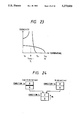
- FIG. 23 shows this relation as a graph.
- the direction of magnetization of the second layer of the recording medium which satisfies the conditions given by Formulas 122 to 124 at the room temperature is aligned in, e.g., "A direction" ( ⁇ ) by Hini. which satisfies the condition given by Formula 125 immediately before recording.
- the first layer is left in the previous recorded state (Condition 1a or 1b in FIGS. 24 and 25).
- Condition 1a or 1b is maintained immediately before recording.
- the bias field (Hb) is applied in a direction of ⁇ .
- the mark in Condition 1a or 1b then reaches the spot region of the laser beam.
- the laser beam intensity includes two levels, i.e., high and low levels like in the basic invention.
- a low-temperature cycle will be described below with reference to FIG. 24.
- Condition 1a Under the presence of Hb ⁇ , (1) in Condition 1a with a magnetic wall, the direction of magnetization of the first layer is reversed, and the magnetic wall disappears, or (2) Condition 1b without a magnetic wall is maintained.
- the high-temperature cycle will be described below with reference to FIG. 25.
- Condition 3 H When the mark falls outside the spot region of the laser beam in Condition 3 H , the medium temperature begins to decrease. When the medium temperature is decreased slightly below T C2 , magnetization appears in the second layer. In this case, magnetization ( ⁇ ) appears by ⁇ Hb. However, since the temperature is still higher than T C1 , no magnetization appears in the first layer. This condition corresponds to Condition 4 H in FIG. 25.
- the medium temperature is then decreased from the temperature in Condition 6 H to the room temperature. Since H C1 at the room temperature is sufficiently large, the magnetization of the first layer is stably maintained. In this manner, formation of a mark in the "non-A direction" is completed.
- FIG. 26 shows this relation as a graph.
- a condition for Hini. is represented by Formula 135. If Hini. disappears, the directions of magnetization of the first and second layers are influenced to each other due to the exchange coupling force.
- the conditions for holding the directions of magnetization of the first and second layers without being reversed are represented by Formulas 133 and 134.
- the medium No. 5 satisfies Formulas 133 and 134: ##EQU27##
- the direction of magnetization of the second layer of the recording medium which satisfies the conditions given by Formulas 132 to 134 at the room temperature is aligned in, e.g., "A direction" ( ⁇ ) by Hini. which satisfies the condition given by Formula 135 immediately before recording: ##EQU28##
- the first layer is left in the recorded state (Condition 1a or 1b in FIGS. 27 and 28).
- Condition 1a or 1b is maintained immediately before recording.
- the bias field Hb is applied in the "non-A direction" ⁇ .
- a condition for preventing the previously recorded mark (in particular, a mark in which the first layer is in Condition 1a opposite to Hb) from being reversed by Hb when it approaches an Hb apply means is represented by Formula 135-2: ##EQU29##
- the disk-like medium must satisfy this formula at the room temperature.
- a condition for preventing the initialized second layer from being reversed by Hb when it approaches the Hb apply means is represented by Condition 135-3: ##EQU30##
- conditions for determining Hb are Formulas 135-2 and 135-3.
- the mark in Condition 1a or 1b then reaches the spot region of the laser beam.
- the laser beam intensity includes two levels, i.e., high and low levels like in the basic invention.
- Condition 1a Under the presence of Hb ⁇ , (1) in Condition 1a with a magnetic wall, the direction of magnetization of the first layer is reversed, and the magnetic wall disappears, or (2) Condition 1b without a magnetic wall is maintained.
- the high-temperature cycle will be described below with reference to FIG. 28.
- the medium temperature is increased beyond T comp .1 ⁇ T L .
- T comp .1 ⁇ T L Upon radiation of a high-level laser beam, the medium temperature is increased beyond T comp .1 ⁇ T L . As a result, a condition without a magnetic wall is established.
- FIG. 1 is a schematic view for explaining a recording principle of a magnetooptical recording method
- FIG. 2 is a schematic view for explaining a reproduction principle of the magnetooptical recording method
- FIGS. 3A and 3B are charts showing an output waveform of a laser beam
- FIG. 4A is a diagram showing a multilayered structure of a recording medium
- FIG. 4B is a diagram showing directions of magnetization of first and second layers of the medium
- FIG. 5 is a graph showing the relationship between a temperature and a coersivity
- FIG. 6 is a diagram showing a change in direction of magnetization at high level in the first category of the basic invention
- FIG. 7 is a diagram showing a change in direction of magnetization at low level in the first category of the basic invention.
- FIG. 8 is a diagram showing changes in direction of magnetization shown in FIGS. 6 and 7 in units of P and A type media;
- FIG. 9 is a diagram showing a change in direction of magnetization at high level in the second category of the basic invention.
- FIG. 10 is a diagram showing a change in direction of magnetization at low level in the second category of the basic invention.
- FIG. 11 is a map showing four types of media
- FIGS. 12A to 12D are graphs showing the relationships between temperatures and coersivities for Type I to Type IV media, respectively;
- FIG. 13 is a graph showing the relationship between a temperature and a coersivity for a medium No. 1-1;
- FIGS. 14 and 15 are diagrams showing changes in direction of magnetization in high- an low-temperature cycles of the medium No. 1-1;
- FIG. 16 is a graph showing the relationship between a temperature and a coersivity for a medium No. 1-2;
- FIGS. 17 and 18 are diagrams showing changes in direction of magnetization in high- and low-temperature cycles of the medium No. 1-2;
- FIG. 19 is a diagram showing conditions with various directions of magnetization of a medium according to the first aspect of the present invention.
- FIG. 20 is a graph showing the relationship between a temperature and a coersivity for a medium No. 1-3 according to the second aspect of the present invention.
- FIGS. 21 and 22 are diagrams showing changes in direction of magnetization in high- and low-temperature cycles of the medium No. 1-3;
- FIG. 23 is a graph showing the relationship between a temperature and a coersivity for a medium No. 3 according to the second aspect of the present invention.
- FIGS. 24 and 25 are diagrams showing changes in direction of magnetization in high- and low-temperature cycles of the medium No. 3;
- FIG. 26 is a graph showing the relationship between a temperature and a coersivity for a medium No. 5 according to the second aspect of the present invention.
- FIGS. 27 and 28 are diagrams showing changes in direction of magnetization in high- and low-temperature cycles of the medium No. 5;
- FIGS. 29 and 30 are graphs showing temperature characteristics of H C1 * of the media according to the second aspect of the present invention.
- FIGS. 31 and 32 are graphs showing differences in various characteristics between a medium according to an embodiment of the present invention, and a medium according to a comparative example.
- a three-element RF magnetron sputtering apparatus is used, and a TbFeCo alloy is used as a target.
- a glass substrate having a thickness of 1.2 mm and a diameter of 200 mm is set in a chamber of the apparatus.
- Table 2 summarizes manufacturing conditions and characteristics of this medium. Values of M S , H C , and ⁇ w (unit: erg/cm 2 ) were obtained at 25° C.
- a two-layered film medium was manufactured following the same procedures as in Embodiment 1 without forming the third layer.
- An exchange coupling force between the first and second layers in this medium was 4.0.
- the value of the left-hand side of Formula 105 is about 2,600 Oe, and the value of the right-hand side is about 23,900 Oe. Therefore, Hini. can be selected from a range of 2,600 to 23,900.
- Formula 103 is calculated for the medium of Comparative Example.
- Hini. can only be selected from a range of 2,750 to 6,110.
- Embodiment 2 and Comparative Example corresponding to the medium of Embodiment 2 excluding the third layer
- the value of the left-hand side of Formula 104 is about 2,600 Oe, and the value of the right-hand side is about 22,300 Oe. Therefore, Hini. can be selected from a range of 2,600 to 22,300.
- Formula 103 is calculated for the medium of Comparative example.
- Hini. can only be selected from a range of 2,750 to 6,110.
- a three-element RF magnetron sputtering apparatus is used, and two alloys, i.e., a TbFeCo alloy and a DyTbFeCo alloy are placed as targets.
- a glass substrate having a thickness of 1.2 mm and a diameter of 200 mm is set in a chamber of the apparatus.
- the target is replaced with the GdTbFeCo alloy while maintaining the vacuum state, and sputtering is similarly performed, thereby forming a second layer (recording layer) comprising a 1,700- ⁇ thick Dy 19 Tb 9 Fe 42 Co 30 perpendicular magnetic film on the first layer.
- Table 4 summarizes manufacturing conditions and characteristics of this medium. Values of M S , H C , and ⁇ w were obtained at 25° C.
- a two-layered magnetooptical recording medium No. 8 belonging to Class 8 (A type, Quadrant IV, Type shown in Table 5 below is manufactured following the same procedures as in Embodiment 3.
- Hb bias field
- (1) a minimum laser beam intensity necessary for completely erasing, in a low-temperature cycle, a "mark having a mark length of 0.75 ⁇ m" formed (recorded) in advance in a high-temperature cycle, and (2) a minimum laser beam intensity necessary for forming a mark in a high-temperature cycle after the mark was completely erased were measured.
- FIG. 31 shows the measurement results.
- 1 represents the former measurement result
- 2 represents the latter measurement result.
- curves 1 and 2 do not intersect with each other, and hence, Hb of 1,200 Oe or higher can be assured, resulting in a large margin.
- FIG. 32 shows the measurement results.
- a medium of Embodiment solid curve
- a margin is kept to assure safety, it is preferable to reproduce information with 1 to 1.5 mW.
- a margin of 0.2 mW in this embodiment can be obtained, this means that a laser beam intensity during reproduction can be increased by about 10 to 20%.
- a C/N ratio can be expected to be increased by about 2 dB.
Applications Claiming Priority (6)
| Application Number | Priority Date | Filing Date | Title |
|---|---|---|---|
| JP1-248519 | 1989-09-25 | ||
| JP1248519A JPH03113753A (ja) | 1989-09-25 | 1989-09-25 | Hini.のマージンが大きなオーバーライト可能な光磁気記録媒体 |
| JP1-280227 | 1989-10-27 | ||
| JP1280227A JPH03142733A (ja) | 1989-10-27 | 1989-10-27 | オーバーライト可能な光磁気記録媒体 |
| JP1310969A JPH03171454A (ja) | 1989-11-30 | 1989-11-30 | T‖の明確なオーバーライト可能な光磁気記録媒体 |
| JP1-310969 | 1989-11-30 |
Publications (1)
| Publication Number | Publication Date |
|---|---|
| US5273835A true US5273835A (en) | 1993-12-28 |
Family
ID=27333723
Family Applications (1)
| Application Number | Title | Priority Date | Filing Date |
|---|---|---|---|
| US07/586,874 Expired - Fee Related US5273835A (en) | 1989-09-25 | 1990-09-21 | Over-write capable magnetooptical recording medium |
Country Status (3)
| Country | Link |
|---|---|
| US (1) | US5273835A (fr) |
| EP (1) | EP0420587B1 (fr) |
| DE (1) | DE69023601T2 (fr) |
Cited By (1)
| Publication number | Priority date | Publication date | Assignee | Title |
|---|---|---|---|---|
| SG105007A1 (en) * | 2002-09-19 | 2004-07-30 | Samsung Electronics Co Ltd | "perpendicular magnetic recording media" |
Families Citing this family (3)
| Publication number | Priority date | Publication date | Assignee | Title |
|---|---|---|---|---|
| US5593790A (en) * | 1994-12-29 | 1997-01-14 | Imation Corp. | Interference super-resolution using two magnetic layer construction |
| US5903526A (en) * | 1996-09-20 | 1999-05-11 | Victor Company Of Japan, Ltd. | Magneto-optical recording medium having multiple magnetic layers |
| JP2000200448A (ja) * | 1998-10-30 | 2000-07-18 | Fujitsu Ltd | 光磁気記録媒体及び光磁気記録媒体の製造方法 |
Citations (3)
| Publication number | Priority date | Publication date | Assignee | Title |
|---|---|---|---|---|
| EP0258978A2 (fr) * | 1986-07-08 | 1988-03-09 | Canon Kabushiki Kaisha | Milieu d'enregistrement magnéto-optique permettant la surécriture avec deux ou plus de deux couches magnétiques et méthode d'enregistrement l'utilisant |
| US4855975A (en) * | 1986-10-08 | 1989-08-08 | Nikon Corporation | Over write capable magnetooptical recording method using two beams, and magnetooptical recording apparatus therefor |
| EP0352548A2 (fr) * | 1988-07-13 | 1990-01-31 | Sony Corporation | Méthode d'enregistrement thermo-magnétique |
Family Cites Families (1)
| Publication number | Priority date | Publication date | Assignee | Title |
|---|---|---|---|---|
| JP2521908B2 (ja) * | 1985-06-11 | 1996-08-07 | 株式会社ニコン | オ―バ―ライト可能な光磁気記録方法、それに使用される光磁気記録装置及び光磁気記録媒体、並びに変調方法、変調装置及び光磁気記録媒体 |
-
1990
- 1990-09-21 US US07/586,874 patent/US5273835A/en not_active Expired - Fee Related
- 1990-09-25 EP EP90310497A patent/EP0420587B1/fr not_active Expired - Lifetime
- 1990-09-25 DE DE69023601T patent/DE69023601T2/de not_active Expired - Fee Related
Patent Citations (3)
| Publication number | Priority date | Publication date | Assignee | Title |
|---|---|---|---|---|
| EP0258978A2 (fr) * | 1986-07-08 | 1988-03-09 | Canon Kabushiki Kaisha | Milieu d'enregistrement magnéto-optique permettant la surécriture avec deux ou plus de deux couches magnétiques et méthode d'enregistrement l'utilisant |
| US4855975A (en) * | 1986-10-08 | 1989-08-08 | Nikon Corporation | Over write capable magnetooptical recording method using two beams, and magnetooptical recording apparatus therefor |
| EP0352548A2 (fr) * | 1988-07-13 | 1990-01-31 | Sony Corporation | Méthode d'enregistrement thermo-magnétique |
Non-Patent Citations (8)
| Title |
|---|
| Patent Abstracts of Japan, vol. 12, No. 284 (P 740) (3131) Aug. 4, 1988 (Abstract only). * |
| Patent Abstracts of Japan, vol. 12, No. 284 (P-740) (3131) Aug. 4, 1988 (Abstract only). |
| Patent Abstracts of Japan, vol. 13, No. 475 (P 950) Oct. 27, 1989 (Abstract only). * |
| Patent Abstracts of Japan, vol. 13, No. 475 (P-950) Oct. 27, 1989 (Abstract only). |
| Patents Abstracts of Japan, vol. 13, No. 520 (P 963) Nov. 21, 1989 (Abstract only). * |
| Patents Abstracts of Japan, vol. 13, No. 520 (P-963) Nov. 21, 1989 (Abstract only). |
| Swartz et al, "The Bell System Technical Journal," vol. 62 (1983), pp. 1923-1936. |
| Swartz et al, The Bell System Technical Journal, vol. 62 (1983), pp. 1923 1936. * |
Cited By (1)
| Publication number | Priority date | Publication date | Assignee | Title |
|---|---|---|---|---|
| SG105007A1 (en) * | 2002-09-19 | 2004-07-30 | Samsung Electronics Co Ltd | "perpendicular magnetic recording media" |
Also Published As
| Publication number | Publication date |
|---|---|
| EP0420587B1 (fr) | 1995-11-15 |
| DE69023601D1 (de) | 1995-12-21 |
| EP0420587A2 (fr) | 1991-04-03 |
| EP0420587A3 (en) | 1992-10-28 |
| DE69023601T2 (de) | 1996-06-13 |
Similar Documents
| Publication | Publication Date | Title |
|---|---|---|
| US5126986A (en) | Over write capable magnetooptical recording medium, recording method and apparatus using the same | |
| JP2521908B2 (ja) | オ―バ―ライト可能な光磁気記録方法、それに使用される光磁気記録装置及び光磁気記録媒体、並びに変調方法、変調装置及び光磁気記録媒体 | |
| US4855975A (en) | Over write capable magnetooptical recording method using two beams, and magnetooptical recording apparatus therefor | |
| US5539709A (en) | Magnetooptical recording method and apparatus using multi-layered media | |
| US5309427A (en) | Overwrite-capable magnetooptical recording medium allowing enlarged margin of high level beam intensity | |
| US5164926A (en) | Over-write capable magnetooptical recording medium with four magnetic layered structure dispensing with external initializing field | |
| US5458987A (en) | Multilayered magnetooptical recording medium | |
| US5343449A (en) | Over-write capable magnetooptical recording medium having reading layer | |
| US5239534A (en) | Multi-layer over write capable magnetooptical recording medium | |
| US5258973A (en) | Method of pre-processing over-write capable magnetooptical recording medium, and pre-processed over-write capable magnetooptical recording medium | |
| US5645911A (en) | Over-writable method of magnetooptical recording | |
| US5014252A (en) | Over write capable magnetooptical recording method using two beams, and magnetooptical recording apparatus therefor | |
| JPH0573981A (ja) | パワーマージンが拡大されたオーバーライト可能な光磁気記録方法及びそれに使用される光磁気記録装置 | |
| US5191564A (en) | Over-write capable magnetooptical recording medium having groove depth of 800 Å or less | |
| EP0420587B1 (fr) | Milieu magnéto-optique capable de surinscription | |
| US5367507A (en) | Over write capable magnetooptical recording method, and magnetooptical recording apparatus and medium used therefor | |
| US5440531A (en) | Magneto-optical reproducing method | |
| US5389455A (en) | Over-write capable magnetooptical recording medium having C/N ratio exceeding 53 dB | |
| US5106704A (en) | Over write capable magnetooptical recording medium | |
| JP2535952B2 (ja) | 磁性層間の交換結合力が制御された多層光磁気記録媒体 | |
| JPH0816996B2 (ja) | 光磁気記録の再生方法及びそれに使用される媒体 | |
| JPH0816993B2 (ja) | 転写層を有するオーバーライト可能な光磁気記録媒体 | |
| JP2712274B2 (ja) | オーバーライト可能な光磁気記録媒体 | |
| EP0373898A2 (fr) | Milieu d'enregistrement magnéto-optique avec capacité de sur-inscription | |
| EP0450237B1 (fr) | Support d'enregistrement magnétooptique surinscriptible à faible force de couplage d'échange |
Legal Events
| Date | Code | Title | Description |
|---|---|---|---|
| AS | Assignment |
Owner name: NIKON CORPORATION, JAPAN Free format text: ASSIGNMENT OF ASSIGNORS INTEREST.;ASSIGNORS:MATSUMOTO, HIROYUKI;SAITO, JUN;REEL/FRAME:005455/0233 Effective date: 19900919 |
|
| FEPP | Fee payment procedure |
Free format text: PAYOR NUMBER ASSIGNED (ORIGINAL EVENT CODE: ASPN); ENTITY STATUS OF PATENT OWNER: LARGE ENTITY |
|
| FPAY | Fee payment |
Year of fee payment: 4 |
|
| FPAY | Fee payment |
Year of fee payment: 8 |
|
| REMI | Maintenance fee reminder mailed | ||
| LAPS | Lapse for failure to pay maintenance fees | ||
| STCH | Information on status: patent discontinuation |
Free format text: PATENT EXPIRED DUE TO NONPAYMENT OF MAINTENANCE FEES UNDER 37 CFR 1.362 |
|
| FP | Lapsed due to failure to pay maintenance fee |
Effective date: 20051228 |