US5732142A - Musical sound reproduction controller with two-stage adjustment of tone - Google Patents
Musical sound reproduction controller with two-stage adjustment of tone Download PDFInfo
- Publication number
- US5732142A US5732142A US08/499,630 US49963095A US5732142A US 5732142 A US5732142 A US 5732142A US 49963095 A US49963095 A US 49963095A US 5732142 A US5732142 A US 5732142A
- Authority
- US
- United States
- Prior art keywords
- tone
- frequency response
- musical sound
- audio signal
- sound
- Prior art date
- Legal status (The legal status is an assumption and is not a legal conclusion. Google has not performed a legal analysis and makes no representation as to the accuracy of the status listed.)
- Expired - Fee Related
Links
Images



Classifications
-
- H—ELECTRICITY
- H03—ELECTRONIC CIRCUITRY
- H03G—CONTROL OF AMPLIFICATION
- H03G5/00—Tone control or bandwidth control in amplifiers
-
- H—ELECTRICITY
- H04—ELECTRIC COMMUNICATION TECHNIQUE
- H04S—STEREOPHONIC SYSTEMS
- H04S7/00—Indicating arrangements; Control arrangements, e.g. balance control
- H04S7/30—Control circuits for electronic adaptation of the sound field
- H04S7/307—Frequency adjustment, e.g. tone control
-
- H—ELECTRICITY
- H04—ELECTRIC COMMUNICATION TECHNIQUE
- H04S—STEREOPHONIC SYSTEMS
- H04S3/00—Systems employing more than two channels, e.g. quadraphonic
-
- H—ELECTRICITY
- H04—ELECTRIC COMMUNICATION TECHNIQUE
- H04S—STEREOPHONIC SYSTEMS
- H04S7/00—Indicating arrangements; Control arrangements, e.g. balance control
- H04S7/30—Control circuits for electronic adaptation of the sound field
- H04S7/305—Electronic adaptation of stereophonic audio signals to reverberation of the listening space
-
- H—ELECTRICITY
- H04—ELECTRIC COMMUNICATION TECHNIQUE
- H04S—STEREOPHONIC SYSTEMS
- H04S7/00—Indicating arrangements; Control arrangements, e.g. balance control
- H04S7/40—Visual indication of stereophonic sound image
-
- Y—GENERAL TAGGING OF NEW TECHNOLOGICAL DEVELOPMENTS; GENERAL TAGGING OF CROSS-SECTIONAL TECHNOLOGIES SPANNING OVER SEVERAL SECTIONS OF THE IPC; TECHNICAL SUBJECTS COVERED BY FORMER USPC CROSS-REFERENCE ART COLLECTIONS [XRACs] AND DIGESTS
- Y10—TECHNICAL SUBJECTS COVERED BY FORMER USPC
- Y10S—TECHNICAL SUBJECTS COVERED BY FORMER USPC CROSS-REFERENCE ART COLLECTIONS [XRACs] AND DIGESTS
- Y10S84/00—Music
- Y10S84/26—Reverberation
Definitions
- the present, invention relates to a sound reproduction control apparatus suitably utilized to adjust a tone of musical sounds reproduced by an amplifier, and utilized to adapt a frequency response of an amplifier to a sound field in which the musical sound is reproduced.
- the frequency response of the amplifier should be adjusted for the actual use and situation so as to realize a desired tone.
- the adjustment of the frequency response for the use and situation is quite important to a specific type of a mixing amplifier called "karaoke amplifier" which amplifies and mixes a live vocal part and an orchestral accompaniment part, because such a mixing amplifier is installed in a public karaoke facility or other places under diverse conditions.
- karaoke amplifier which uses four to six member of loudspeakers separately located to reproduce the musical sound by improved presence.
- Another type of the karaoke amplifier is provided with function to simulate a sound field such as a concert-hall and a stadium. In order to fully exhibit such a simulative function, it is necessary to adjust the frequency response of the karaoke amplifier for the actual use and situation.
- a tone of the reproduced music composition is adjusted according to user's choice.
- the karaoke amplifier reproduces diverse number of songs, hence the tone of the reproduced sound is frequently adjusted to match a melody of an individual song by varying the frequency response of the karaoke amplifier.
- the individual tone adjustment for the melody or the like would deteriorate the basic tone adjustment for the use and situation, thereby disadvantageously obstructing full performance of the amplifier.
- an object of the invention is to provide a sound reproduction control apparatus constructed to maintain the basic tone adjusted for a specified use and situation while allowing tone variation adjusted for individual musical compositions or the like.
- a reproduction characteristic control apparatus comprises first frequency response control means for controlling a frequency response to an input signal, signal processing means for applying a predetermined signal process to an output signal of the first frequency response control means, and second frequency response control means for controlling a frequency response to an output signal of the signal processing means.
- a reproduction characteristic control apparatus comprises first frequency response control means for controlling a frequency response to a stereophonic input signal, signal processing means for producing and outputting a multiple of channel signals based on an output signal of the first frequency response control means, and second frequency response control means for controlling a frequency response to each channel signal outputted from the signal processing means.
- a sound reproduction control apparatus processes an audio signal in reproduction of a musical sound to control a tone of the musical sound while imparting an effect to the musical sound.
- the apparatus comprises first tone controller means having a variable frequency response for amplifying the audio signal by the variable frequency response so as to variably control the tone of the musical sound, processor means connected to the first tone controller means for processing the audio signal to impart a desired effect to the musical sound, and second tone controller means connected to the processor means and having an adjustable frequency response adjusted separately from the variable frequency response of the first tone controller means for amplifying the audio signal by the adjusted frequency response so as to adjustively control the tone of the musical sound.
- the second frequency response controller means or second tone control means has the adjustable frequency response which is adjusted according to the specific use and situation of the amplifier, while the first, frequency response control means or the first tone controller means has the variable frequency response which is freely adjusted according to a user's desire. Consequently, the tone of the reproduced sound can be freely varied in matching with a melody or the like, while maintaining the basic or fundamental tone of the reproduced sound, which is adapted to the use and situation such as a sound field.
- the basic frequency response is adjusted for each of the final outputs of the multiple channels so as to achieve more practical tone control.
- the adjustment or setting of the frequency response of the second tone controller means is prohibited unless a specific switch operation is carried out, thereby avoiding inadvertent change of the adjustment and maintaining the fundamental tone of the sound.
- FIG. 1 is a block diagram showing a first embodiment of the present invention.
- FIG. 2 is a circuit diagram showing a two-band tone control circuit provided in the first embodiment.
- FIG. 3 is a block diagram showing a second embodiment of the present invention.
- FIG. 4 is a screen view showing graphic operation in the second embodiment.
- FIG. 5 is another screen view showing the graphic operation in the second embodiment.
- FIG. 6 is a further screen view showing the graphic operation in the second embodiment.
- FIG. 1 is a block diagram showing a construction of the first embodiment according to the invention.
- This embodiment is directed to a karaoke amplifier as one application of the invention.
- the apparatus has a vocal amplifier unit 1 which receives a voice signal or live vocal audio signal from a microphone (not shown in the figure), which then applies various processes to the voice signal, and thereafter which amplifies the same for outputting. More specifically, the voice signal is inputted from the microphone to both of parallel input terminals T1 and T2 through an A/D converter (not shown).
- the voice signal received at the input terminal T1 is fed through a three-band tone control circuit (TC) 2 and a subsequent three-band equalizer (EQ) 3 to those of an echo processor 4, a reverberation processor 5 and a modulation processor 6.
- the three-band tone control circuit 2 has various curves of a frequency response, which are preset at factory in matching with desired types of a sound field. Further, the three-band equalizer 3 has a certain frequency response which is preset at factory suitably for vocal performance reproduction.
- the echo processor 4 superposes an echo signal to the voice signal, which is then fed to a pair of adders 11L and 11R through respective buffers 10L and 10R.
- the reverberation processor 5 superposes a reverberation signal to the voice signal, which is then fed to the respective ones of the adders 11L and 11R through parallel buffers 12L and 12R.
- the modulation processor 6 applies a desired modulation such as pitch shift to the voice signal, which is then fed to the respective ones of the adders 11L and 11R through parallel buffers 13L and 13R.
- An output signal from the adder 11L is fed to each of subsequent adders 30 and 32 through buffers.
- an output signal from the other adder 11R is fed to each of subsequent adders 31 and 33 through buffers.
- the original voice signal received at the separate input terminal T2 from the microphone is directly fed to each of the adders 11L and 11R through parallel buffers 14L and 14R.
- the apparatus further includes a musical sound amplifier unit 18 which receives a stereophonic digital musical sound signal or stereophonic audio signal at terminals T3 and T4, which then converts the sound signal into four channel signals corresponding to front left, front right, rear left, and rear right channels of the sound reproduction, and thereafter which amplifies and outputs these four channel signals to corresponding ones of front left speaker SP-FL, front right speaker SP-FR, rear left speaker SP-RL and rear right speaker SP-PR.
- the musical sound amplifier 18 includes a key control circuit, (KC) 20 which operates according to commands for effecting pitch control of the inputted digital sound signal representative of a musical composition such as an orchestral accompaniment of a karaoke song. Namely, the key control circuit 20 controls the key of the musical composition to be reproduced.
- KC key control circuit
- the thus key-controlled digital stereophonic sound signal is fed to a two-band tone control circuit 21L of a left, channel L, and is also fed to another two-band tone control circuit 21R of a right channel R.
- These tone control circuits variably determine a sound quality or tone of the reproduced sound at lower and higher frequency bands.
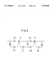
- FIG. 2 is a block diagram showing a construction of the two-band tone control circuits 21L and 21R.
- the circuit is composed of delay elements D, adder elements S1 and S2, amplifier elements A1a, A1b and A1c which attribute to tone control of the lower frequency band, and other amplifier elements A2a, A2b and A2c which attribute to tone control of the higher frequency band.
- a gain variation of the amplifier element A1c dominantly influences a frequency range variation of the lower band as well as a gain variation of the amplifier element A2c dominantly influences a frequency range variation of the higher band.
- a gain variation of the amplifier elements A1a and A1b dominantly influences an output gain or amplitude level variation of the lower band
- a gain variation of the amplifier elements A2a and A2b dominantly influences an output gain variation of the higher band. Therefore, the gains of the amplifier elements A1a, A1b and A1c are selectively set to adjust the frequency range and the amplitude level of the lower band, while the gains of the amplifier elements A2a, A2b and A2c are selectively set to adjust the frequency range and the amplitude level of the higher band.
- the output signals from the two-band tone control circuits 21L and 21R are fed, respectively, to four-band parametric equalizers 22L and 22R, where desired equalizing characteristics are imparted to the fed signals.
- An output signal of the left four-band parametric equalizer 22L is distributed to each of the adders 30, 31, 32 and 33 through buffers. The same output signal is separately fed to an intermediate adder 24 through a buffer 23L.
- an output signal of the right four-band parametric equalizer 22R is distributed to each of the adders 30-33 through buffers. The same output signal is separately fed to the intermediate adder 24 through a buffer 23R.
- An output signal of the adder 24 is fed to an initial or first echo generator 25, where initial echo signals in four directions of front left (FL), front right (FR), rear left (RL) and rear right (RR) are generated and superposed to the sound signal to form four directional audio signals.
- the adders 30, 31, 32 and 33 correspond to respective ones of the four directions FL, FR, RL and RR, and are connected to receive through the buffers the corresponding ones of the four directional signals outputted from the initial echo generator 25.
- the initial echo generator 25 processes the sound signal to create an effect in the form of an echo signal corresponding to a selected one of preset sound fields. Stated otherwise, the initial echo generator 25 generates the echo signal according to control parameters memorized correspondingly to the selected preset sound field.
- a detailed construction of such an initial echo generator is described, for example, in Japanese Utility Model Application Laid-open No. 2-112100 (1990).
- the musical sound amplifier unit 18 contains a reverberation generator 26 which is provided to supplementally generate another effect in the form of a reverberation signal in case that the echo signal generated by the initial echo generator 25 cannot fully reconstruct the desired sound field.
- the echo effect provided by the initial echo generator 25 may not be sufficient to alone reproduce a sound field of a room space such as a church having a long reverberation duration.
- the reverberation generator 26 supplements a necessary reverberation effect.
- An output signal of the reverberation generator 26 is formed in the four directions FL, FR, RL and RR. The four directional components of the sound signal are distributed to the corresponding adders 30, 31, 32 and 33, respectively.
- the reverberation generator 26 may be composed of a comb filter and a cascaded all-pass filters.
- Respective output signals of the adders 30, 31, 32 and 33 are fed to an output or power amplifier 50 through corresponding ones of two-band tone control circuits 40, 41, 42 and 43, each of which has the same structure as shown in FIG. 2.
- Output signals of the respective two-band tone control circuits 40-43 are inputted into the amplifier 50.
- the amplifier 50 converts the inputted digital signals of the four directions FL, FR, RL and RR into analog signals by means of a D/A converter, and then carries out power amplification of the analog signals, which are distributed to the corresponding speakers SP-FL, SP-FR, SP-RL and SP-RR.
- the use and situation includes external condition such as configuration, dimension, wall material, window size and window position of a room in which the apparatus is installed, and an internal condition such as transmission characteristics of the power amplifier 50 and the speakers.
- the room configuration etc. may be varied dependently on installation spots, and the transmission characteristics of the power amplifier and the speakers may vary among individual commercial products.
- the basic or fundamental frequency response should be adjusted to a specific use and situation of the individual apparatus.
- initial gain control is conducted in the amplifier elements A1a-A1c and A2a-A2c of the respective two-band tone control circuits 40-43 so as to adjust the tone of the musical sound emitted from the respective loudspeakers.
- the gain control may be manually conducted while listening to test sounds emitted from the loudspeakers.
- the two-band tone control circuits 40-43 are adjusted to obtain a desired tone of the test sound reproduced through the loudspeaker.
- the adjustment may be carried out with the aid of a measurement device.
- the tone may be adjusted differently among the multiple of the loudspeakers, or adjusted uniformly for each loudspeaker.
- gain control volumes are commonly interconnected between the two-band tone control circuits 40 and 41.
- the two-band tone control circuits 42 and 43 are concurrently and commonly adjusted with each other if there is no substantial tone difference therebetween. Further, the adjustment is achieved to eliminate tone difference between the front pair of the speakers SP-FL and SP-FR, and the rear pair of the speakers SP-RL and SP-RR.
- the tone adjustment is conducted to adapt the frequency response of the two-band tone control circuits 40-43 to the specified use and situation. Stated otherwise, the frequency response is adapted to the sound field specified by the use and situation of the karaoke amplifier.
- the musical sound signal is amplified according to the frequency response which is set as described above to thereby reproduce the musical sound having the tone adapted to the use and situation of the karaoke amplifier.
- the user sings a vocal performance with the microphone in matching with the reproduced sounds of the karaoke accompaniment.
- the singing voice is also amplified by the vocal amplifier unit 1, and is then emitted from the loudspeakers SP-FL, SP-FR, SP-RL and SP-RR together with the automatic orchestral accompaniment to form a composite karaoke performance.
- gain control volumes of the first or preceding two-band tone control circuits 21L and 21R are manipulated to vary the basic tone of the reproduced musical sound in matching with a specific melody of the musical composition.
- the tone is varied according to the gain factors of the preceding two-band tone control circuit 21L and 21R, while the gain factors of the succeeding two-band tone control circuits 40-43 are fixed so as to well maintain their frequency responses initially adjusted to the use and situation.
- the gain factors of the first or preceding two-band tone control circuits 21L and 21R are freely adjusted to vary the volume level of the sound in either of the higher and lower bands separately from the basic frequency response adapted to the use and situation.
- the tone can be freely adjusted to the melody and the like without deviating from the basic tone adapted to the use and situation.
- the preceding two-band tone control circuits 21L and 21R alone are utilized to effect overall tone control without providing the second or succeeding two-band tone control circuits 40-43, the actual tone may be seriously deviated from a desired one matching the use and situation.
- FIG. 3 is a schematic block diagram showing the second embodiment of the inventive apparatus.
- This embodiment utilizes a computer to carry out by software process the gain adjustment of the two-band tone control circuits 40-43 which are the same as the first embodiment.
- a CPU 60 operates based on a program stored in a ROM 61.
- An operation panel 62 is manually operated to input various commands into the CPU 60.
- a display controller 63 displays various images on a screen of a monitor 64.
- the display controller 63 has an internal video RAM, and stores various picture information, icons and image data.
- a gain controller 65 operates under the control by the CPU 60 to control gains of the amplifier elements A1a-A1c and A2a-A2c within the two-band tone control circuits 40-43.
- a digital volume is provided to adjust the gain of the two-band tone control circuits 40-43.
- the gain controller 65 controls each digital volume.
- the panel 62 is operated to select an initial setting mode. For example, while a particular switch is depressed, a power switch is turned on to call the initial setting mode.
- the CPU 60 detects such a specific sequence of the switch operation to establish the initial setting mode.
- the initial setting mode is never established unless such a sequential switch operation is detected.
- the display controller 63 displays a guide message of the initial setting mode on a screen of the monitor 64.
- FIG. 4 shows the guide screen, where a message "INSTALLATION MENU" is displayed on an upper zone of the screen to indicate that the initial setting mode is established. Further, an instruction “MENU 1: ⁇ ” is displayed on a lower zone of the screen. This instruction indicates that depression of an arrow key provided on the panel 62 causes updating of menu item number. Then, the arrow key is actually depressed to successively scroll menu items of various setting modes.
- the monitor When the particular menu is selected to set the frequency response, the monitor displays a message on the screen as shown in FIG. 5.
- a message "SPEAKER TONE CONTROL” is indicated on the top zone of the screen to indicate that the setting of the frequency response is allowed.
- marks "MAIN” and “REAR” are indicated on a central zone of the screen together with an arrow which points either of "MAIN” and “REAR,”.
- the mark “MAIN” designates the front speakers SP-FL and SP-FR, and the mark “REAR.” designates the rear speakers SP-RL and SP-RR.
- An up arrow key or a down arrow key is depressed to select one of the marks "MAIN” and "REAR". Either of right and left arrow keys is depressed to enter adjustment of the frequency response.
- the right or left arrow key is depressed while the mark "MAIN" is designated, so that the screen is switched as shown in FIG. 6 to display a virtual representation of the actual frequency response.
- a message "MAIN SP TONE CONTROL” is displayed on the upper zone of the screen to indicate the tone control mode of the front speakers.
- the central zone of the screen displays two rows of "HIGH” which designates the higher band and "LOW” which designates the lower band.
- the respective rows include indicators Ia and Ib which indicate levels.
- a pointing arrow is displayed to indicate which of "HIGH” and "LOW” is selected. Then, the up and down arrow keys are operated to select a desired band.
- the right and left arrow keys are actuated by graphic operation to displace the indicator Ia in a direction corresponding to the actuated arrow key.
- the gain controller 65 adjusts the gain of the amplifier elements A2a-A2c contained in the two-band tone control circuits 40 and 41 according to the position of the indicator Ia.
- the gain of the amplifier elements Ala-Alc contained in the two-band tone control circuits 40 and 41 is automatically adjusted according to the position of the indicator Ib.
- the gain of the amplifier elements A1a-A1e and A2a-A2c of the two-band tone control circuits 42 and 43 is adjusted according to the graphic operation on the screen shown in FIG. 6.
- the frequency response of the karaoke amplifier is adjusted to the use and situation. Thereafter, the karaoke amplifier is operated in manner similar to the first embodiment. For example, the gain of the preceding two-band tone control circuits 21L and 21R is adjusted to obtain a tone variation as desired by the user in matching with a musical composition or else.
- the initial basic frequency response adapted to the sound field can be well reserved in the second embodiment.
- the gain factors of the lower and higher bands in the two-band tone control circuits 21L and 21R are automatically adjusted to a sound field to be simulated. Namely, the level of the respective band is provisionally memorized for different types of sound fields. The appropriate level is retrieved correspondingly to a selected type of the sound field for the automatic setting.
- the amplifier receives an input signal in the form of a monaural signal or a multi-channel signal rather than the stereophonic signal of the disclosed embodiments.
- the present invention can be applied not only to the karaoke amplifier of the disclosed embodiments, but also to a regular audio amplifier.
- the fundamental frequency response adapted to the use and situation can be well reserved while a tone variation is freely introduced according to a melody of musics or else.
Landscapes
- Physics & Mathematics (AREA)
- Engineering & Computer Science (AREA)
- Acoustics & Sound (AREA)
- Signal Processing (AREA)
- Reverberation, Karaoke And Other Acoustics (AREA)
- Stereophonic System (AREA)
- Tone Control, Compression And Expansion, Limiting Amplitude (AREA)
- Circuit For Audible Band Transducer (AREA)
- Electrophonic Musical Instruments (AREA)
Applications Claiming Priority (2)
| Application Number | Priority Date | Filing Date | Title |
|---|---|---|---|
| JP6179589A JP2876993B2 (ja) | 1994-07-07 | 1994-07-07 | 再生特性制御装置 |
| JP6-179589 | 1994-07-07 |
Publications (1)
| Publication Number | Publication Date |
|---|---|
| US5732142A true US5732142A (en) | 1998-03-24 |
Family
ID=16068377
Family Applications (1)
| Application Number | Title | Priority Date | Filing Date |
|---|---|---|---|
| US08/499,630 Expired - Fee Related US5732142A (en) | 1994-07-07 | 1995-07-07 | Musical sound reproduction controller with two-stage adjustment of tone |
Country Status (4)
| Country | Link |
|---|---|
| US (1) | US5732142A (ja) |
| JP (1) | JP2876993B2 (ja) |
| KR (1) | KR100249681B1 (ja) |
| GB (1) | GB2291319B (ja) |
Cited By (8)
| Publication number | Priority date | Publication date | Assignee | Title |
|---|---|---|---|---|
| US5902950A (en) * | 1996-08-26 | 1999-05-11 | Yamaha Corporation | Harmony effect imparting apparatus and a karaoke amplifier |
| US6068489A (en) * | 1995-10-23 | 2000-05-30 | Yamaha Corporation | Karaoke amplifier with variably settable range of parameter to control audio signal |
| US6127617A (en) * | 1997-09-25 | 2000-10-03 | Yamaha Corporation | Effector differently controlling harmonics and noises to improve sound field effect |
| NL1025634C2 (nl) * | 2004-03-04 | 2005-09-07 | Circle Music Systems | Inrichting voor het verwerken van audiosignalen, geluidsinstallatie voor het verwerken van audiosignalen, werkwijze voor het verwerken van audiosignalen en een computerprogramma voor het uitvoeren van een dergelijke werkwijze. |
| US20070129842A1 (en) * | 2000-12-11 | 2007-06-07 | United Parcel Service Of America, Inc. | Method & system for performing a package pre-load operation in accordance with a dispatch plan |
| US20080192945A1 (en) * | 2007-02-08 | 2008-08-14 | Mcconnell William | Audio system and method |
| US20090060209A1 (en) * | 2007-08-31 | 2009-03-05 | Victor Company Of Japan, Ltd. A Corporation Of Japan | Audio-signal processing apparatus and method |
| JP2013051595A (ja) * | 2011-08-31 | 2013-03-14 | Yamaha Corp | スピーカ装置 |
Families Citing this family (2)
| Publication number | Priority date | Publication date | Assignee | Title |
|---|---|---|---|---|
| JP4281601B2 (ja) * | 2004-03-30 | 2009-06-17 | ブラザー工業株式会社 | 情報通信システム、通信カラオケ端末、配信用ホスト装置及びプログラム |
| JP4983360B2 (ja) * | 2007-04-16 | 2012-07-25 | ヤマハ株式会社 | 音響特性補正システム |
Citations (25)
| Publication number | Priority date | Publication date | Assignee | Title |
|---|---|---|---|---|
| US3812278A (en) * | 1972-02-01 | 1974-05-21 | Kustom Electronics | Special effect amplifier for electrical musical instruments |
| US4114497A (en) * | 1975-09-29 | 1978-09-19 | Nippon Gakki Seizo Kabushiki Kaisha | Electronic musical instrument having a coupler effect |
| US4203340A (en) * | 1979-01-26 | 1980-05-20 | O/R Inc. | Electronic musical instrument |
| US4237019A (en) * | 1977-12-23 | 1980-12-02 | Imperial Chemical Industries Limited | 1-Thiocyanato-8-substituted naphthalene compounds and their use as biocides |
| GB1598746A (en) * | 1977-04-25 | 1981-09-23 | Victor Company Of Japan | Signal processing circuit for binaural signals |
| GB2098031A (en) * | 1981-03-10 | 1982-11-10 | Victor Company Of Japan | Noise reducing apparatus |
| WO1983002700A1 (en) * | 1982-01-26 | 1983-08-04 | Bloy, Ghaham, Philip | System for maximum efficient transfer of modulated energy |
| EP0166543A2 (en) * | 1984-05-31 | 1986-01-02 | Pioneer Electronic Corporation | Mobile sound field correcting device |
| US4586417A (en) * | 1981-07-28 | 1986-05-06 | Nippon Gakki Seizo Kabushiki Kaisha | Electronic musical instruments provided with reverberation tone generating apparatus |
| US4628789A (en) * | 1984-06-01 | 1986-12-16 | Nippon Gakki Seizo Kabushiki Kaisha | Tone effect imparting device |
| US4683589A (en) * | 1983-12-28 | 1987-07-28 | Scholz Research & Development | Electronic audio system |
| US4809336A (en) * | 1987-03-23 | 1989-02-28 | Pritchard Eric K | Semiconductor amplifier with tube amplifier characteristics |
| JPH02112100A (ja) * | 1988-10-21 | 1990-04-24 | Hitachi Ltd | 配車システム |
| US4984497A (en) * | 1986-11-28 | 1991-01-15 | Yamaha Corporation | Tone signal generation device having a tone element control function |
| US4991484A (en) * | 1988-01-06 | 1991-02-12 | Yamaha Corporation | Tone signal generation device having a sampling function |
| US4995084A (en) * | 1987-03-23 | 1991-02-19 | Pritchard Eric K | Semiconductor emulation of tube amplifiers |
| JPH03113478A (ja) * | 1989-09-27 | 1991-05-14 | Casio Comput Co Ltd | 自動演奏装置 |
| US5050216A (en) * | 1985-09-13 | 1991-09-17 | Casio Computer Co., Ltd. | Effector for electronic musical instrument |
| US5157215A (en) * | 1989-09-20 | 1992-10-20 | Casio Computer Co., Ltd. | Electronic musical instrument for modulating musical tone signal with voice |
| US5172415A (en) * | 1990-06-08 | 1992-12-15 | Fosgate James W | Surround processor |
| US5216718A (en) * | 1990-04-26 | 1993-06-01 | Sanyo Electric Co., Ltd. | Method and apparatus for processing audio signals |
| US5241604A (en) * | 1990-01-24 | 1993-08-31 | Kabushiki Kaisha Toshiba | Sound effect apparatus |
| US5261005A (en) * | 1990-10-09 | 1993-11-09 | Yamaha Corporation | Sound field control device |
| US5448009A (en) * | 1992-07-07 | 1995-09-05 | Yamaha Corporation | Electronic musical instrument including tone generator controller capable of conducting efficient control on different types of tone generators |
| US5477003A (en) * | 1993-06-17 | 1995-12-19 | Matsushita Electric Industrial Co., Ltd. | Karaoke sound processor for automatically adjusting the pitch of the accompaniment signal |
Family Cites Families (2)
| Publication number | Priority date | Publication date | Assignee | Title |
|---|---|---|---|---|
| JPH0410009A (ja) * | 1990-04-26 | 1992-01-14 | Sanyo Electric Co Ltd | デジタルデータの非線形変換方法及びこれを用いた信号処理装置 |
| JP3077600U (ja) * | 2000-11-08 | 2001-05-25 | 日本ジャバラ工業株式会社 | 布製ジャバラ。 |
-
1994
- 1994-07-07 JP JP6179589A patent/JP2876993B2/ja not_active Expired - Lifetime
-
1995
- 1995-07-07 US US08/499,630 patent/US5732142A/en not_active Expired - Fee Related
- 1995-07-07 GB GB9513862A patent/GB2291319B/en not_active Expired - Fee Related
- 1995-07-07 KR KR1019950020010A patent/KR100249681B1/ko not_active Expired - Fee Related
Patent Citations (25)
| Publication number | Priority date | Publication date | Assignee | Title |
|---|---|---|---|---|
| US3812278A (en) * | 1972-02-01 | 1974-05-21 | Kustom Electronics | Special effect amplifier for electrical musical instruments |
| US4114497A (en) * | 1975-09-29 | 1978-09-19 | Nippon Gakki Seizo Kabushiki Kaisha | Electronic musical instrument having a coupler effect |
| GB1598746A (en) * | 1977-04-25 | 1981-09-23 | Victor Company Of Japan | Signal processing circuit for binaural signals |
| US4237019A (en) * | 1977-12-23 | 1980-12-02 | Imperial Chemical Industries Limited | 1-Thiocyanato-8-substituted naphthalene compounds and their use as biocides |
| US4203340A (en) * | 1979-01-26 | 1980-05-20 | O/R Inc. | Electronic musical instrument |
| GB2098031A (en) * | 1981-03-10 | 1982-11-10 | Victor Company Of Japan | Noise reducing apparatus |
| US4586417A (en) * | 1981-07-28 | 1986-05-06 | Nippon Gakki Seizo Kabushiki Kaisha | Electronic musical instruments provided with reverberation tone generating apparatus |
| WO1983002700A1 (en) * | 1982-01-26 | 1983-08-04 | Bloy, Ghaham, Philip | System for maximum efficient transfer of modulated energy |
| US4683589A (en) * | 1983-12-28 | 1987-07-28 | Scholz Research & Development | Electronic audio system |
| EP0166543A2 (en) * | 1984-05-31 | 1986-01-02 | Pioneer Electronic Corporation | Mobile sound field correcting device |
| US4628789A (en) * | 1984-06-01 | 1986-12-16 | Nippon Gakki Seizo Kabushiki Kaisha | Tone effect imparting device |
| US5050216A (en) * | 1985-09-13 | 1991-09-17 | Casio Computer Co., Ltd. | Effector for electronic musical instrument |
| US4984497A (en) * | 1986-11-28 | 1991-01-15 | Yamaha Corporation | Tone signal generation device having a tone element control function |
| US4809336A (en) * | 1987-03-23 | 1989-02-28 | Pritchard Eric K | Semiconductor amplifier with tube amplifier characteristics |
| US4995084A (en) * | 1987-03-23 | 1991-02-19 | Pritchard Eric K | Semiconductor emulation of tube amplifiers |
| US4991484A (en) * | 1988-01-06 | 1991-02-12 | Yamaha Corporation | Tone signal generation device having a sampling function |
| JPH02112100A (ja) * | 1988-10-21 | 1990-04-24 | Hitachi Ltd | 配車システム |
| US5157215A (en) * | 1989-09-20 | 1992-10-20 | Casio Computer Co., Ltd. | Electronic musical instrument for modulating musical tone signal with voice |
| JPH03113478A (ja) * | 1989-09-27 | 1991-05-14 | Casio Comput Co Ltd | 自動演奏装置 |
| US5241604A (en) * | 1990-01-24 | 1993-08-31 | Kabushiki Kaisha Toshiba | Sound effect apparatus |
| US5216718A (en) * | 1990-04-26 | 1993-06-01 | Sanyo Electric Co., Ltd. | Method and apparatus for processing audio signals |
| US5172415A (en) * | 1990-06-08 | 1992-12-15 | Fosgate James W | Surround processor |
| US5261005A (en) * | 1990-10-09 | 1993-11-09 | Yamaha Corporation | Sound field control device |
| US5448009A (en) * | 1992-07-07 | 1995-09-05 | Yamaha Corporation | Electronic musical instrument including tone generator controller capable of conducting efficient control on different types of tone generators |
| US5477003A (en) * | 1993-06-17 | 1995-12-19 | Matsushita Electric Industrial Co., Ltd. | Karaoke sound processor for automatically adjusting the pitch of the accompaniment signal |
Non-Patent Citations (3)
| Title |
|---|
| British Search Report dated Oct. 11, 1995, Appl. No. GB 9513862.4. * |
| Radio Designer s Handbook Edited by F. Langford Smith Fourth Edition, 1953 ILIFFE, London, pp. 661, 999. * |
| Radio Designer's Handbook Edited by F. Langford Smith Fourth Edition, 1953 ILIFFE, London, pp. 661, 999. |
Cited By (15)
| Publication number | Priority date | Publication date | Assignee | Title |
|---|---|---|---|---|
| US6068489A (en) * | 1995-10-23 | 2000-05-30 | Yamaha Corporation | Karaoke amplifier with variably settable range of parameter to control audio signal |
| US5902950A (en) * | 1996-08-26 | 1999-05-11 | Yamaha Corporation | Harmony effect imparting apparatus and a karaoke amplifier |
| US6127617A (en) * | 1997-09-25 | 2000-10-03 | Yamaha Corporation | Effector differently controlling harmonics and noises to improve sound field effect |
| US8068930B2 (en) | 2000-12-11 | 2011-11-29 | United Parcel Service Of America, Inc. | Method and system for performing a package pre-load operation in accordance with a dispatch plan |
| US20070129842A1 (en) * | 2000-12-11 | 2007-06-07 | United Parcel Service Of America, Inc. | Method & system for performing a package pre-load operation in accordance with a dispatch plan |
| US9214000B2 (en) | 2000-12-11 | 2015-12-15 | United Parcel Service Of America, Inc. | Method and system for performing a package pre-load operation in accordance with a dispatch plan |
| US7421311B2 (en) | 2000-12-11 | 2008-09-02 | United Parcel Service Of America, Inc. | Method and system for performing a package pre-load operation in accordance with a dispatch plan |
| US8688266B2 (en) | 2000-12-11 | 2014-04-01 | United Parcel Service Of America, Inc. | Method and system for performing a package pre-load operation in accordance with a dispatch plan |
| US20090187272A1 (en) * | 2000-12-11 | 2009-07-23 | United Parcel Service Of America, Inc. | Method & system for performing a package pre-load operation in accordance with a dispatch plan |
| NL1025634C2 (nl) * | 2004-03-04 | 2005-09-07 | Circle Music Systems | Inrichting voor het verwerken van audiosignalen, geluidsinstallatie voor het verwerken van audiosignalen, werkwijze voor het verwerken van audiosignalen en een computerprogramma voor het uitvoeren van een dergelijke werkwijze. |
| US20080192945A1 (en) * | 2007-02-08 | 2008-08-14 | Mcconnell William | Audio system and method |
| EP2031902A3 (en) * | 2007-08-31 | 2010-09-15 | Victor Company Of Japan, Limited | Audio-signal processing apparatus and method |
| US20090060209A1 (en) * | 2007-08-31 | 2009-03-05 | Victor Company Of Japan, Ltd. A Corporation Of Japan | Audio-signal processing apparatus and method |
| JP2013051595A (ja) * | 2011-08-31 | 2013-03-14 | Yamaha Corp | スピーカ装置 |
| US9253585B2 (en) | 2011-08-31 | 2016-02-02 | Yamaha Corporation | Speaker apparatus |
Also Published As
| Publication number | Publication date |
|---|---|
| KR960006259A (ko) | 1996-02-23 |
| JP2876993B2 (ja) | 1999-03-31 |
| GB9513862D0 (en) | 1995-09-06 |
| KR100249681B1 (ko) | 2000-03-15 |
| JPH0823595A (ja) | 1996-01-23 |
| HK1008384A1 (en) | 1999-05-07 |
| GB2291319B (en) | 1999-04-28 |
| GB2291319A (en) | 1996-01-17 |
Similar Documents
| Publication | Publication Date | Title |
|---|---|---|
| US5939656A (en) | Music sound correcting apparatus and music sound correcting method capable of achieving similar audibilities even by speaker/headphone | |
| JPS63183495A (ja) | 音場制御装置 | |
| JPH04296200A (ja) | 音響装置 | |
| US4815133A (en) | Sound field producing apparatus | |
| KR100249681B1 (ko) | 2단계 음조 제어기능을 가지는 악음재생제어기 | |
| JPH10304498A (ja) | ステレオ拡大装置及び音場拡大装置 | |
| US5543579A (en) | Effector | |
| JP2003005752A (ja) | 電子楽器 | |
| JP4196509B2 (ja) | 音場創出装置 | |
| JP2886402B2 (ja) | ステレオ信号発生装置 | |
| JP2000059897A (ja) | 音声再生装置および音声再生方法 | |
| JPH04242684A (ja) | 対話型ビデオゲーム装置 | |
| JPH0415693A (ja) | 音源情報制御装置 | |
| US5434923A (en) | Acoustic apparatus | |
| JPS63177699A (ja) | 自動車の音響装置 | |
| JPH08286687A (ja) | カラオケ装置 | |
| JP3266045B2 (ja) | ステレオシステム | |
| JPH05191898A (ja) | 音像拡大装置 | |
| KR0135451B1 (ko) | 디지탈 노래반주 시스템의 오디오 설정 방법 | |
| JPH0638300A (ja) | 音響再生装置 | |
| US6399868B1 (en) | Sound effect generator and audio system | |
| JPH06319198A (ja) | オーディオ装置 | |
| JP3242900U (ja) | 音響出力装置 | |
| JPS61237599A (ja) | 音場制御装置 | |
| JPH04341000A (ja) | 音響装置 |
Legal Events
| Date | Code | Title | Description |
|---|---|---|---|
| AS | Assignment |
Owner name: YAMAHA CORPORATION, JAPAN Free format text: ASSIGNMENT OF ASSIGNORS INTEREST;ASSIGNORS:NAGATA, YUICHI;SUZUKI, SATOSHI;REEL/FRAME:007605/0494 Effective date: 19950621 |
|
| FEPP | Fee payment procedure |
Free format text: PAYOR NUMBER ASSIGNED (ORIGINAL EVENT CODE: ASPN); ENTITY STATUS OF PATENT OWNER: LARGE ENTITY |
|
| FPAY | Fee payment |
Year of fee payment: 4 |
|
| FPAY | Fee payment |
Year of fee payment: 8 |
|
| REMI | Maintenance fee reminder mailed | ||
| LAPS | Lapse for failure to pay maintenance fees | ||
| STCH | Information on status: patent discontinuation |
Free format text: PATENT EXPIRED DUE TO NONPAYMENT OF MAINTENANCE FEES UNDER 37 CFR 1.362 |
|
| FP | Lapsed due to failure to pay maintenance fee |
Effective date: 20100324 |