WO1982002164A1 - Method of controlling wire cut electric discharge machining apparatus - Google Patents
Method of controlling wire cut electric discharge machining apparatus Download PDFInfo
- Publication number
- WO1982002164A1 WO1982002164A1 PCT/JP1981/000344 JP8100344W WO8202164A1 WO 1982002164 A1 WO1982002164 A1 WO 1982002164A1 JP 8100344 W JP8100344 W JP 8100344W WO 8202164 A1 WO8202164 A1 WO 8202164A1
- Authority
- WO
- WIPO (PCT)
- Prior art keywords
- machining
- wire
- deflection
- corner
- amount
- Prior art date
- Legal status (The legal status is an assumption and is not a legal conclusion. Google has not performed a legal analysis and makes no representation as to the accuracy of the status listed.)
- Ceased
Links
Classifications
-
- B—PERFORMING OPERATIONS; TRANSPORTING
- B23—MACHINE TOOLS; METAL-WORKING NOT OTHERWISE PROVIDED FOR
- B23H—WORKING OF METAL BY THE ACTION OF A HIGH CONCENTRATION OF ELECTRIC CURRENT ON A WORKPIECE USING AN ELECTRODE WHICH TAKES THE PLACE OF A TOOL; SUCH WORKING COMBINED WITH OTHER FORMS OF WORKING OF METAL
- B23H7/00—Processes or apparatus applicable to both electrical discharge machining and electrochemical machining
- B23H7/02—Wire-cutting
- B23H7/06—Control of the travel curve of the relative movement between electrode and workpiece
- B23H7/065—Electric circuits specially adapted therefor
Definitions
- the present invention relates to a control method for preventing a machining error at the time of corner machining caused by deflection of a wire electrode during electric discharge machining during wire electric discharge machining.
- a control method for preventing a machining error at the time of corner machining caused by deflection of a wire electrode during electric discharge machining during wire electric discharge machining we will be deterred by the control method of wire-to-not discharge machines that can precisely process the corners using a particularly simple method.
- the principle of electric discharge machining is that a specified gap is maintained between the wire electrode and the gap, and a voltage is applied between the wire electrode and the fork. A spark discharge is generated in the lever, and the work is cut off by the discharge energy. Therefore, the work is performed based on the machining command data.
- the workpiece can be processed into a desired shape by moving it to the 15 electrode.
- the wire 1 is taken out from the reel Lj, and is taken out from the lower guide 4 and the upper guide. It is stretched between 4 and
- U ' 0 ,-, V It can be processed into any shape.
- the upper guide 4 is also moved by the motors MU and MV. Movement to move in the X and Y directions respectively. ⁇ Mounted on the structure, the upper guide 4 is also moved to move in the X-Y direction. It is.
- the numerical value NC is used to read the contents of the command tape TP (read i), and to process each line in response to the command by the minute S circuit 103.
- the motors MX, MY, MU, and MV are operated by SVY, SVU, and SVV to operate the tape TB and the transfer contacts, and to process the work 2 into the desired shape. It is a thing.
- the wire 1 is connected to the work 2 as shown in the operation diagram of Fig. 2.
- a pressure for discharging is generated between the wire electrode 1 and the work 2, and
- the wire electrode 1 is moved in the direction of the arrow, that is, in the direction opposite to the traveling direction. Therefore, the wire power 1 is behind the position of the wire guides 4 and 4.
- the wire wire 1 will bend. In the case of electric discharge machining for H ⁇ longevity, the amount of deflection does not significantly affect machining precision.
- the wire fence 1 of the dead portion was pulled inside the corner CN, and the machining trajectory of the groove 3 was commanded.
- the shape is different from the shape (shown in actuality). As shown by the dotted lines, the kana]?
- the machining error in the arcuate corner portion or the angled corner portion can be changed by changing the machining path, machining power, feed], speed, etc. It is known to be improved.
- the combination of these processing conditions is limited to the number of ⁇ , and the specific criterion of how to control the basis, feed speed, and machining voltage is 3 ⁇ 4. It was really realistic.
- An object of the present invention is to provide a method for controlling wire cut electrical discharge machining, which can improve the wire cut.
- the present invention provides a wire-cut electric discharge machining system that can improve the corner shape of the corner portion and perform the precision corner machining by simply changing the feeding speed.
- the goal is to provide a method. .
- the amount of deflection due to the electric discharge of the wire electrode is detected during the electric discharge machining of the workpiece, and the electric discharge machining condition of the corner portion is determined from the detected amount of deflection.
- the electric discharge machining of the corner is performed by moving the electric motor under these immersed electric discharge machining conditions. Go.
- the control method of the invention since the processing error of the corner is caused by the deflection of the wire electrode, the deflection amount of the wire electrode is detected, and the deflection amount is detected based on the deflection amount.
- FIGS. 1 and 2 are explanatory views of a wire cutter EDM object to which the present invention is applied
- FIG. 3 is an explanatory view illustrating the deflection of the wire
- FIGS. 4 and 5 Is a diagram explaining the machining error due to the deflection, which is the subject of development
- FIG. 5 is the arc according to the present invention, in which the arc is formed at the corner of the arc.
- FIG. ⁇ is an illustration of the method for measuring the amount of deflection used for kishi
- FIG. 9 is a circuit diagram of the sensing device used for koki
- Fig. 10 The figure is a block diagram of an embodiment of the present invention.
- BEST MODE FOR CARRYING OUT KISHI Hereinafter, an embodiment of the present invention will be described in detail with reference to the drawings.
- Figure m6 illustrates the t ⁇ method of the present invention in an arc-shaped corner.
- 1 and 2 are the surface of the wire
- 1 is the wire electrode at the bending position that has undergone the deflection due to the power failure
- 1 is the wire that is at the wire guide position.
- the ear electrode, 2 is a work
- 5 is an arc-shaped machining groove subjected to electric discharge machining by a bent wire electrode.
- the machining radiation is 2 s «> and the radius of the center is 2 s R
- F 0 is positive, normal feed command speed, F is reduced feed speed, is a constant o-
- FIG. 7 is an explanatory view showing a control method of the present invention in a corner-shaped corner portion composed of two straight lines LL2.
- Equation ( ⁇ ) means moving a circle with a radius R instructed at a speed of F, and is equivalent to moving an arc whose diameter is divided by ⁇ at a command speed Fa. And 3 ⁇ 4 3 ⁇ 4 ⁇ .
- the machining feed stop time is determined by the following formula:
- Td F (7) ⁇ , where 6 is the corner angle.
- FIG. 8 is an explanatory view for explaining the deflection amount measuring method.
- each indicates a new surface of the wire electrode
- 1 indicates the position of the wire electrode at the maximum deflection amount
- 2 indicates the position of the wire electrode at the guide position
- 3 is the electric discharge machined.
- the measurement of the amount of deflection is performed as follows. Immediately
- Discharge is stopped once at a predetermined measurement point (Fig. 7) during machining. Due to the termination of the discharge, the applied voltage force acts, and the bent wire electrode “!” Is pulled in the guide direction (A direction in the figure) and corrodes the work 2. If the wire connection 1 is connected to the work 2, the sensing device will be confused.
- the ninth ⁇ ⁇ ⁇ ⁇ ⁇ 3 ⁇ 4 3 ⁇ 4 3 ⁇ 4 R R R R wire Electrode is the work
- PS is the machining electrode
- COM is the comparator
- R! R is a resistor
- Tr is a transistor for applying a processing voltage between the wire and the work
- DD is a diode
- VL is a detection level. If the voltage between the wire electrode WIR and the work WK is not short, the voltage of one Vo is input to the comparator COM. Although it operates, if a short circuit occurs, the comparator COM whose potential at point A becomes zero-Hall is activated, the corrosion signal TS is output, and the S fault is detected.
- the discharge circuit is controlled by the machining power supply P S , and the diode DD and the resistors R 2 , R 3 .
- the Te ⁇ Tsu in FIG. 8 when the word i ya electrode 1 Shokusuru against the word over click 2, Shi pairs state to Wa Lee Ya Den ⁇ 1 was Se' this the word over click 2 relative Specifically, it is moved along the machining path. ⁇
- the wire guide discharge process configured to move the guide may be performed by moving the guide to the work 2 and retreating in the direction of arrow B.
- g is the gap of the electric power
- the machining groove ⁇ is 2 s as shown in Fig.8.
- Wire! If ⁇ . Is set to 0,
- ⁇ Deflection measurement is performed by inputting an auxiliary function “Lunli M2 Q” for drowning in the program during the program. '
- Fig. 1Q is a lock diagram for implementing the present invention.
- 1 02 Ebb b pressurizing g is perforated Ebb log La Mute flop, the Pulse distributor, 1 04 Wa Lee ya force, 3 ⁇ 4 sensing device 1 C a in preparative EDM ⁇ , and inner ⁇ the etc.
- the deflection amount j is set under the control of the ⁇ -gram, and the processing unit 1 Q 1b is set to the 3 ⁇ 4-gram memory.
- the processing unit 1 Q 1 b executes the deflection of the deflection amount of the control memory 10 1 c and the programmed radius of the programmed arc radius R, -Corner angle 3 ⁇ 4 ⁇ , command sent. And around the deflection amount Do (from equation or equation ( 8 ))? Difference gF or 7J0 The trapping time is calculated each time and the shape of the corner is corrected.
- the shape of the corner portion can be improved by a simple method, and the effect is great.
Landscapes
- Chemical & Material Sciences (AREA)
- Chemical Kinetics & Catalysis (AREA)
- Electrochemistry (AREA)
- Engineering & Computer Science (AREA)
- Mechanical Engineering (AREA)
- Electrical Discharge Machining, Electrochemical Machining, And Combined Machining (AREA)
Description
钥 細 甞
ワ イ ヤ カ ッ ト 放電加工機の制御方法 ,
Ψ
' 技 術 分 野
本発明は、 ワ イ ヤ カ ツ ト 放電加工接に ける放電加工 s 中の ワ イ ヤ電極のたわみに よ っ て生 じ る コ ー ナ加工時の 加工誤差を防止 し う る制御方法に関 し、 特に容易 な 万法 に よ っ て コ ー ナ部を精度良 く 加工 し う る ワ イ ヤ 力 -ノ ト 放 電加工機の制御方法に鬨する。
背 景 技 銜
10 ワ イ ヤ カ ツ ト 放電加工接の原理は、 ワ イ ヤ電極 と ヮ一 ク 間に所定の ギ ヤ ッ ブを保た しめ、 かつ ワ イ ヤ電 と フ ー ク 間に電圧き 印加 して こ の ギ ヤ ブ閭 に火花放電を発 生せ しめ、 その放鼋 エ ネ ル ギ ー にて ワ ー ク を削 取 る も の て あ る。 従'つ て、 加工指令デー タ に基いて ワ ー ク を ヮ
15 ィ ャ電極に対 し稆对的に移動せ しめれば所望の形状に該 ワ ー ク ¾:加工で き る。
即ち、 第 1 図の周知の ワ イ ヤ カ ツ ト 放電加工接の概略 説明図に示す様に、 ワ イ ヤ 1 は リ ー ル Lj か ら譟出され て下ガイ ド 4 と上ガ イ ド 4 と の間に張設され が ら リ ー
20 ル RL2に巻取 られ、 図示 しない接 ¾電裎に よ っ て電圧が 加え られ る こ と に よ ワ ー ク 2 と の間に放電 ^生 じて、 ワ ーク 2 を ί/Πェする も のて ある 。 一 '方、 ワ ー ク 2 はモ ー タ MX, MYに よ ]3 それぞれ X , Y方问に移動され る X 一 Yテー ブ ル 丁 B上に固定さ れ てい るのて、 X - Y テ ー プ
2S ル T B を X , Y方 问に移 す る こ と に よ ]? 、 ワ ー ク 2 を
C).-?I
U '0 、-、 V
任意の形犾に加工する こ と ができ る。 又、 上ガイ ド 4 も モー タ MU, MVに よ ΐ? それぞれ X , Y方 f¾に移動する移 動《構に取付け られ、 上ガイ ド 4 も X - Y方向に移動出 来る様養^されて る。
コ ラ ム C Mには前述の移動接搆、 リ ー ル RL2 , 下ガ イ ド 4 が取付け られて る。
数値剞蜀装置 N Cは指令テ ー プ T P の内容 ¾読取 i) 、 分 S回路 1 03に よ って指令に対する各翱の分 ¾処¾を行 い、 各軸に対応する恵動回路 SVX, SVY, SVU, SVVに よ つ て各 のモ ー タ MX, MY, MU, MV 動 して、 テー プ ル T B及び移勣接搆を動泎せ しめ、 ワ ーク 2 を所望形状 に加工する も のである。
'こ の X う な ワ イ ヤ カ プ ト 放電加工機に:^ て 、 第 2 図 のその動作説 ¾図に示す よ う に ワ イ ヤ電¾ 1 が ワ ー ク 2 ¾故電に ょ ^ 削 が らその溝 5 を所定方向に違むと き、 第 3 図の新面図に示すよ う に、 ワ イ ヤ電裎 1 と ワ ー ク 2 間に放電のための圧力が生 じ、 結果的に ワ イ ヤ電 ¾ 1 は 矢印方向す わ ち進行方向 と 逆向の方向へ钾 し戾される。 このため、 ワ イ ヤ電 1 は ワ イ ヤ ガ イ ド 4 , 4 の位置 よ 後^する。 す ¾わち ワ イ ヤ電 ¾ 1 がたわむこ と と る。 H籙壽の放電加工を行る つ て る場合には、 このたわみ 量はさ ほ ど加工精変に影響 ¾与えず 題に ¾ ら 。 し か し、 コ ー ナー 形 ¾する加工に際 しては こ のたわみ 量が大き る問題と る。 ち、 箅 4 図の ェ濤正面図に 示す ¾に第 1 の!:篛壽 L 1 と H¾ ffi L 1 ?1"角の第 2 の
直籙溝 L 2 て構成さ れる 溝 3 の形成のため には、 第 1 , 第 2 の直鎳篱 L i, L 2 の交点に コ ー ナ部 C N を加工に よ 形成 しな く てはな ら な い。 このため、 ワ ー ク 2 と ワ イ ャ ¾¾ 1 と の一方向の相対移動に よ つ て第 1 の直篛濤 L1 s の形成後、 第 2 の直篛濤 L 2 の形成のた め加工指令に よ 当 該稆对移動を直角方向に変更する必要があ る。 しか し、 前記放電に よ る ワ イ ヤ電極 1 のたわみのため、 故電 部分の ワ イ ャ電桎 1 が コ ーナ部 C N の内側へ引ず られ、 溝 3 の加工軌跡は指令された形状 ( 実篛 にて示す ). と は 異な 、 点鎮て示す よ う に、 かな ]? 内镯にかた上 ]? 、 そ の加工形状がだれて しま う 。
同様に、 第 5 図の加工濤正面図 に示す様に、 第 1 の直 籙壽 L 1 と第 2 の直籙溝 L 2 の コ ー ナ部 CN'を 円弧状に 加工する篛に も 、 前記放電に よ る ワ イ ヤ電極 1 のたわみ のため、 コ ー ナ部 C Tの 加工孰跡は実線て示す指令され た形状に ¾ し、 点籙て示すだれた加工形 ^ と な っ て しま う 。
と こ ろて、 .か る 円弧状 コ ー ナ部 あ るいは角度を し て る コ ー ナ部に ける 加工誤差は加工経路、 加工電篛、 送 ]? 速度 どを変更する こ と に よ 改善され る こ と が知 られている。 しか しな が ら、 これ ら加工条件の組み合せ は ^数に ぁ 、 しか も どの よ う 基阜て ? Πェ经络、 送 速窆、 加工電漯電圧を制御する かの具 ^的 基準が ¾ く ¾雄て現実的で ¾ かっ た。
^ つ て、 2 ^癸 ^ 、 簡单 な 万法 て コ ー ナ ¾の だ
を改善する こ とがてき る ワ イ ヤ カ ツ ト 放電加工接の制御 方法を提供する こ とを 目 的 とする。
又、 本発明は、 送 i? 速度を変更するだけて、 コ ー ナ部 の形状だれを改善 し、 精度の艮ぃ コ ーナ加工を行い う る ワ イ ヤ カ ク ト 放電加工^の制 ^方法を提供する こ と を 目 的 とする 。 .
発 明 の 開 示
本発钥制 方法では、 ワ ー クの放電加工中に ワ イ ヤ電 極の故電に よ るたわみ量を検出 し、 この検出されたたわ み量か ら コ ー ナ部の放電加工条件と して指令速度又は ¾ 対移動の停止時間の少な く と も ずれか一方を演算 し、 こ の漬箕された放電加工条件で稆对移動を劁街 して コ 一 ナ部の放電加工を行る. う も のてあ る。 即ち、 末発明制御 方法ては、 コ ー ナ部の加工誤差が ワ イ ヤ電極のたわみに よ って生 じる こ とか ら、 ワ イ ヤ電裎のたわみ量を検出 し、 たわみ量によ つて コ ー ナ部の加工誤差が生 じない様に、 放電加工条伴の 1 つてあ る ヮ ィ ャ電蓬と ワ ー ク との招対 移動の速度' :又は停止^間を剞镯する も のて ¾る。
図面の簡単る説钥
第 1 図 及び第 2 図は本発明の対象 とする ワ イ ヤ カ ツ 卜 放電加工接の説明図、 第 3 図は ワ イ ヤ のたわみを説 钥する説明図、 第 4 図及び第 5 図は: ¾発 ¾の譟題 と る たわみに よ る加工誤差を説明する説 図、 第 ό 図は円弧 ^コ — ナ部に 、け る本発明に よ る コ ー ナ 忒修正制 ¾方
S 第 7 図は角 ^ コ ーナ =に る ^ よ る 一 Ο ?Ι
ΥΓΙ?0 :
コ ー ナ形状修正制 ¾i方法説明図、 第 δ 図は 癸 ¾ に用い られるたわみ量測定万法説明図、 第 9 図は本癸明に ¾い られ る 鲑感知装置の回路図、 第 1 0 図は本癸 ¾の一実 施例ブ ロ ッ ク 図 である 。 癸钥を実旄するための最良の形態 以下、 本発明の実 ^例を図 に 従っ て詳細に説明する。 m 6 図は円弧状コ ー ナ部に ける本 明の t ¾方法説 明図 であ る。
図中、 1 , は共に ワ イ.ャ電 の靳面であ 、 1 は故 電に よ るたわみを受けたたわみ位置に ける ヮ ィ ャ電極、 は ワ イ ヤ ガ イ ド位置に け る ワ イ ヤ電極、 2 は ワ ー ク、 5 はたわみを受けた ヮ ィ ャ電極に よ つ て放電加工された 円弧 の加工溝であ 、 その加工篱輻は 2 s«>、 その中心 の半径は R て あ る。
さ て、 第 図に示す円弧形状の加工に いては、 直線 加工時の ワ イ ヤ電極のたわみ量 ¾ Daとする と 、 円弧接線 方向のたわみ量 DT及び半径内倒万向のたわみ量 Diiはそれ ぞれ
= D (1)
4
DR = — D, (2)
3 'て R
と な る。 尙、 半径方向のたわみ量 DSは、 刀 (3ェ壽 S の外倜 と 内倒に い て加工量が異る る ため に生 じる。
従っ て、 ) , (2)式か ら前述の半径 R の円 濞の形成の ため、 指令円 ¾半径を外側方向に補正すべ き 量 は
ά R = DT2 ÷ ( R +DR )2 一 R
4
+ ( + ― - — D |2 一 R (3)
3 π R
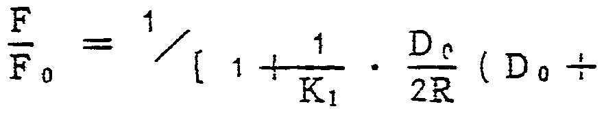
と な る。 と ころて半径方向のたわみ量 DSが R に比べて小 さ い場合には竽径箱正量 R は近似的に
D A R ί=· 〔 Do 4- 0 〕 ( )
2R
と ¾ る。
この よ う に、 円 ¾ϋ半径の補正に よ って、 ワ イ ヤ電裎の たわみに よ る加工誤差を榣正する こ と がて き るが、 座標 系の褶正を行 う と、 これに锈 く 第 2 の!:籙壽等の座標 も 変更せざる をえず、 いささか処理が複 ϋと ¾ る。 つ て、 本発钥では、 送 ]? 速窆を変えて同等の幼杲を得る も の であ る。 即ち、 送 ' 透度 ¾下げる と 邡工濞 3 の幅は 加する 今、 こ の; οαェ壽辐の増加量 を
F0 - F Fo - F
· (5)
Fo * F
と 伋定する。 即ち、 加工濞耰の増加量^ ί gが送 ]?速窆の续 少の割合に比例する も の と 仮定する。 简、 (5)式に いて
F0は正.常 送 指令速度、 F は渎少させた送 速度、 は定数である o -
(4)式の J R と(5)式の ¾等 しい と く と、
R
{6) と る る。 诅 し D° ( D0 ÷ 8 て るる
2 ι . 3
以上か ら、 (ό)式に よ 定ま る祠正送 ]? 速愛 F で竿径 R O コ ー ナ ¾を : ¾ェす ίΐば ¾ ^ 正がで き る と え る。 街、
この修正方法は、 送 速度 を半径 R 、 たわみ量 D。等に応 じて浚速 し、 これに よ ^ 加工溝幅を増邡 して コ ー ナの形 状だれ を修正す る も のてあ る。 このため、 コ ー ナ部の 凹 部 ¾状 ETC ( 第 5 図 ) を改善て き るが、 凸部 ITC ( 第 5 ϋ ) の形状は改善で き な い と 考え られ る 。 し し、 実際 には 凹部の加工に よ つ て ヮ ィ ャ電接が円 のタ'ト镯方问に 移動する ため同時に凸部 も か ]? 艮 く 改眷て き る。
第 7 図は 2 つの直鏢 L L2よ 成る角状コ ー ナ部に ける本発明の制御方法を說钥する 説明図て ある 。
さ て、 (ό)式は指令された半径 R の円 を速 £ F て移動 させる こ と を意味 し、 ^ だけ 径が增分 した円弧を指 令速度 Faて移動させる こ と と 同等の こ と ¾ ¾ ^ して いる。
一方、 第 7 図の コ ー ナ部 CM Sに いて半径 R は ^小で、 殆んど零で ある 。 従っ て、 第 7 図の コ ー ナ ¾の加工形杖 の修正は前述の円 ®状コ ーナ部 と 同様に考える と、 コ ー ナ点 よ も だけ外側の絰路を指令速 て加工すれ ば よ い こ と にな る。 、 は(ό)式に定数され る R - Do . _ . 8
Do + ) て ある
2 3 π
従っ て、 第(0)式の S を 铵小 と すれば、 福正された送 ]? を零とすれば よ い。 即ち、 ヮ ィ ャ電氇 ¾ ^式て定ま る加工送 停止時間
Td の間停止すれば よ い と にな る
Td = F (7) 尙、 式中 6 は コ ー ナ角度で あ る 。
と こ ろて、 実 ^に、 コ ー ナ点て ;]ェを停止 る と 、 こ
C :-'?1
れは Rが锼小の状態の加工と 同 じて、 コ ーナの外側のみ が加工される状態 と る るか ら修正定数を袅けて停止時間 Td ¾
とする。 尙、 (ό) (8)式の定数 , K2は実験 ¾に定め られる。 以上の様に、 ワ イ ヤ電極 1 のたわみ量を検出て き れば、 このたわみ量か ら指令された形状に誤差な く 放電加工す るための指令速度 F や停止時間 Tdを濱箕に よ 得る こ と が出来る 。
この ワ イ ヤ電璲 1 のたわみ量の測定について、 次に説 §9する。
第 8 図はたわみ量測定方法を説明する 説明図てあ る。 図中、 は共に ワ イ ヤ電極の新面であ 、 1 は、 最大たわみ量に ける ワ イ ヤ電極位置を示 し、 はガイ ド位置に ける ワ イ ヤ電極位置を示す。 2 は ワ ー ク、 3 は放電加工された瀵であ る。
さ て、 たわみ量の測定は以下の .鎮序て行な われる。 即 ち、 ま ず
加工中 に て、 所定の測定点 ( 第 7 図 ) で一度放電 を停止する。 この放電停止に よ 、 故電圧力が作用 し く るた め、 たわんていた ワ イ ヤ電極 "! は ガ イ ド方向 ( 図の A方向 ) に引張 られて ワ ー ク 2 に薆蝕する。 ワ イ ャ電接 1 が ワ ー ク 2 に接 ¾すれば , 感知装置が この蓥 ¾ ¾惑知す る。
第 9 な ^ ¾ , ¾装 ¾の回 ¾ てあ リ 、 R ワ イ ャ
電極、 は ワ ー ク 、 P S は加工電漯、 COMはコ ン パ レ ー タ、 R! 〜 R<は抵抗、 Trは加工電圧を ワ イ ヤ - ワ ー ク間 に印加する ため の ト ラ ン ジ ス タ 、 D D は ダ イ オ ー ド、 VL は検出 レ ベ ル てあ る。 さ て、 ワ イ ヤ電極 WIRと ワ ー ク W K間が短終 して な い場合には、 一 Voの電圧がコ ンパ レ ー タ COM 入力されているため コ ン パ レ ー タ COMは作 動 し ¾いが、 短絡する と A点の電位が零ホ'ル ト と る コ ン パ レ 一 タ COMが作動 して接蝕信号 T S が出 力されて S 絡が検出される。
尙、 ト ラ ン ジ ス タ Tr、 抗 I !、 加工電源 PSて放電回路 を搆 し、 ダ イ オー ド D D、 抵抗 R2, R3. コ ン パ レ ー タ COMが接触惑知装置 ¾搆成する。
さ て、 第 8 図に戾つ て、 ワ イ ヤ電極 1 が ワ ー ク 2 に接 蝕する と 、 こ の接斂 した状態か ら ワ イ ヤ電溼 1 を ワ ー ク 2 に対 し相対的 に加工羟路に沿っ て後 ^させ る。 尙、 上 記後退制芻に祭 しては、 ワ ー ク 2 が載置さ れたテ ー ブ ル ¾矢印 A方冋に ワ イ ャ 1 に対 して相対的に移動させて 良 い し、 或いは ガ イ ドを移動て き る構成の ワ イ ヤ カ グ 卜 放 電加工 ^ては該ガ イ ド を ワ ー ク 2 に对 して矢印 B 方向に 後退させて も よ い。
さ て、 上記後退剞御を続行する ワ イ ヤ電¾ と ワ ー ク の 接憨がいつか 涂さ れる 。 従っ て、 放電停止位置か ら ヮ ィ ャ電極 と ワ ー ク と の ¾が 除される位置ま ての後退 を ^定 して N c 内葳の メ モ リ に記憧す る。
つい て、 真のた 7 み量 Dpを ^式に よ っ て 算すれ た w "二 Aリ ' 、 V'"I?0 -
わみ量の測定は終了する。
Do = g 4- ≤ι (?)
但 し、 g は ¾電の ギ ャ ッ プて あ 、 第 8 図 に示す如 く 加工溝 ^を 2 s。 、 ワ イ ヤ !:经.を 0と すれば、
g == ( 2 に 0) Z2 (10)
に よ ]? 求ま る。 ¾つ て、 予め加工濤輻 と ワ イ ヤ径 0を i定 して N C に入力 して けば、 {?\ (10) 式の濱箕を行 う こ と に よ ]? たわみ量が求ま る 。 尙、 この よ う に s0, 0 を予め測定 して入力 して いて も 良いが ^の よ う 処涅 を行 つ て放電ギ ヤ プ ブ g を剽定 して も よ い。 ち、 前 述の後退制御に よ ]? ワ イ ヤ電裎 1 と ワ ー ク 2 と の ^蝕が 除された ら、 加工方向 ( 加工经路 ) と 直角方向に ワ イ ャ電 ¾を移動させ、 再び該 ワ イ ヤ電氇と ワ ー ク が接蝕 する位置迄の钜齄を測定 し、 該钜鏟を ¾電ギ ヤ プ ブ と し、 (9)式 よ たわみ量!)。を求める。
と ころで、 加工条袢に よ っ ては潮定点て放電を停止 し た漦 ワ イ ヤ ¾種 1 と ワ ー ク 2 が接 ¾ し い こ とがある。 これは ワ イ ヤ電毪 1 と ワ ーク 2 間に前述の故電 ギ ャ ッ プ g が ワ イ ヤ電¾ 1 のたわみ量 よ 大き ためて あ る。 か ^ る場合には、 裒言すれば棻斂惑知装置が ¾電停止後に ワ イ ャ電 ^と ワ ー クの簦蝕を惑知 し ¾ 場合に は、 ヮ ィ ャ電裎 1 を加工: 5问へ ワ ー ク 2 に S憨する迄前違させ、 その前逞 m韹 ミ 潮定 し、
Do = g - (11)
O S寘を行 っ てたわみ量 DQを求め る 。
以上がたわみ量測定の詳細であるが、 実際に ワ ー ク の 板厚が厚い と 加工溝中 に切 ]} 屑があ つた i? 、 加工液の電 導度に よ 検出 した後退钜齄 D0は大き めにな る。 そ こ て 真のたわみ量を ^式に よ っ て求め て る 。
Do = £j + g - K3 H (12)
但 し、 Κ3は定数、 Ηは ワ ー ク の複厚であ る。
尙、 たわみ量測定は プ ロ グ ラ ム 中にたおみ量溺定のた めの補助機能侖令 M2 Qを入力 して く こ と に よ 行われ る 。 '
第 1 Q 図は本発钥 を実施する ロ ッ ク図てあ る。 図中、 1 CMは コ ン ピ ュ ー タ構成の N C であ 、 制御プ ロ グ ラ ム メ モ リ 1 0 1 a 、 処理装置 l Q 1 b 、 デー タ メ モ リ 1 0 1 c 、 テ ー プ リ ーダ 1 0 1 (1 ¾ ど ¾有 して る。 尙、 制御ブ ロ グ ラ ム メ モ リ 1 0 1 a には数値制 処理の制淘 プ ロ グ ラ ム の ほかたわみ量測定処理 ブ = グ ラ ム 、 たわみ量補正の プ ロ グ ラ ム な どが記億されて いる。 1 02は エブ ロ グ ラ ム が 穿孔された加エブ ロ グ ラ ムテー プ、 はパ ル ス分配器、 1 04は ワ イ ヤ 力 ,ト 放電加工^で ¾感知装置 1 C a 、 サ ー ボ回路 i a 4 b その他強電回路 1 0 4 c ど を内葷 して いる。
N C は; 3Πエ ブ 。 グ ラ ム テ ー プ "I Q 2か ら福助接能侖令
M 20が読出 される と たわみ量 j定 ^理ブ α グ ラ ム の制 ¾ 下に置かれ、 処理装置 1 Q 1 b は劊 ¾ ブ ロ グ ラ ム メ モ リ
1 0 1 c のたわみ量測定 プ ロ グ ラ ム を実行 し、 前 述の シ ー ケ ン ス ¾つ て ワ イ ヤ '!: のた わみ量 D。を ¾ Sす る n ]¾
デー タ メ モ リ 1 CM c には予め (i2) 式 よ jJ D。を ¾算するた めのバ ラ.メ ー タ てある - 加工溝幅 、 ワ イ ヤ径 0、 夜厚 H、 定数 K3が入力されて る。
潮定終了後、 処理装置 1 Q 1 b は制^ブコ グ ラ ム メ モ リ 101 c のたわみ量梢正プ α グ ラ ム き実行 し、 プ ロ グ ラ ム された円弧半径 R、 コ ー ナ角 ¾ β 、 指令送 達 。及び たわみ量 Doを周 いて( 式或 は(8)式か ら送 ]? 違 g F 又は 7J0ェ俘止時間 をその都度求め コ一ナの形状だれを.修正 する。
尙、 発明 に よ 実際に加工 した結杲、 円 ¾状コ ー ナ の外側 ( 凹部 ) に て加工誤差を数 - ¾下に、 内倒の 凸 ¾に い て形 ^だれ を 7 0〜 8 0 ^程 g续小させる こ と か'て き、 加工精度を向上させる こ と がて き る。
本発明に よ.れぱ籣単な手法て コ ー ナ部の形状だ れを ¾善する こ と がて き その効杲は大き い。
. ΐ··:?ο
Claims
3 請 求 の 範 囲
1- ワ イ ヤ電極 と ワ ー ク と 間 に放電を癸生させる と と も に該 ワ イ ヤ電 ¾と ワ ー ク と を指令速度て稆対移動 して、
?1令された形状に該 ワ ー ク を放電加工する ワ イ ヤ カ ツ ト
5 放電加工機の制珣方法に い て 、
該 ワ ー ク の放電加工中に該 ヮ ィ ャ電裎の放電に よ るた わみ量を検出する検出ス テ ッ ブ と、
該検出さ れたたわみ量か ら コ ーナ部の放電加工条件 と しての該.? 合速度又は相対移動俘止時間の少 〈 .と も
1 0 ずれか一方を湏算する演算ス テ ッ プ と 、
コ ー ナ ^の加工の際、 該演算された加工条 ^に従っ て 該相対移動を制御する制 ス テ ッ ブと を備える こ と を特 徵 とする ワ イ ヤ カ ク 卜 放電加工接の制御.方法。
2. 前記漬算ス テ ク ブに いて、 前記たわみ量、 栺定 i s された円弧半径、 加工幅壽及び指定された指令 ¾ g ¾:用 いて該指定さ Λた円弧半径の円弧 コ ー ナ部に け る前記 指令速度 を演算する こ と を特徴 とす る請求の範囹第 1 項 記載の ワ イ ヤ カ ツ 卜 放電加工 ¾の制御方法。
3. 前記濱箕ス テ ッ プに:^いて、 前記たわみ量、 ΖΙΠェ 0 幅 *、 コ ー ナ角 度及び指令速度を用いて該指定さ れた角 状 コ ー ナ部に ける ¾对移動停止時間 を演算する こ と を卷 徵と する請求の範囲第 1 項記載の ワ イ ヤ カ ツ ト.放電加工 ί¾の剞街方法。 5 "二《"v {J
C ? i
/ ,''' - ' 八 V
Priority Applications (1)
| Application Number | Priority Date | Filing Date | Title |
|---|---|---|---|
| DE8181903076T DE3176481D1 (en) | 1980-12-29 | 1981-11-18 | Method of controlling wire cut electric discharge machining apparatus |
Applications Claiming Priority (2)
| Application Number | Priority Date | Filing Date | Title |
|---|---|---|---|
| JP55185431A JPS57114327A (en) | 1980-12-29 | 1980-12-29 | Method for correcting corner shape |
| JP80/185431801229 | 1980-12-29 |
Publications (1)
| Publication Number | Publication Date |
|---|---|
| WO1982002164A1 true WO1982002164A1 (en) | 1982-07-08 |
Family
ID=16170658
Family Applications (1)
| Application Number | Title | Priority Date | Filing Date |
|---|---|---|---|
| PCT/JP1981/000344 Ceased WO1982002164A1 (en) | 1980-12-29 | 1981-11-18 | Method of controlling wire cut electric discharge machining apparatus |
Country Status (5)
| Country | Link |
|---|---|
| US (1) | US4546227A (ja) |
| EP (1) | EP0067876B1 (ja) |
| JP (1) | JPS57114327A (ja) |
| DE (1) | DE3176481D1 (ja) |
| WO (1) | WO1982002164A1 (ja) |
Cited By (2)
| Publication number | Priority date | Publication date | Assignee | Title |
|---|---|---|---|---|
| US4703143A (en) * | 1984-12-25 | 1987-10-27 | Amada Company, Limited | Wire EDM method for preventing wire lagging during machining of an angular corner and workpiece position control |
| US4725706A (en) * | 1984-10-25 | 1988-02-16 | Inoue Japax Research Incorporated | Tw-electroerosion utilizing cyclically reduced cutting feed rate |
Families Citing this family (19)
| Publication number | Priority date | Publication date | Assignee | Title |
|---|---|---|---|---|
| JPS58120428A (ja) * | 1981-12-30 | 1983-07-18 | Fanuc Ltd | ワイヤカツト放電加工機の制御法 |
| US4629854A (en) * | 1983-02-15 | 1986-12-16 | Inoue-Japax Research Incorporated | TW-electroerosion with means for regulating flushing liquid in cutting slot |
| CH665374A5 (fr) * | 1985-03-28 | 1988-05-13 | Charmilles Technologies | Procede et dispositif pour la determination de la fleche d'un fil a decouper par electroerosion. |
| JPS63267121A (ja) * | 1987-04-22 | 1988-11-04 | Amada Co Ltd | ワイヤ−カツト放電加工装置 |
| EP0378280A1 (fr) * | 1989-01-13 | 1990-07-18 | Charmilles Technologies S.A. | Dispositif et procédé pour contrôler la variation d'un paramètre en électroérosion avec un fil-électrode |
| JP2818429B2 (ja) * | 1989-02-01 | 1998-10-30 | 株式会社アマダ | ワイヤ放電加工機におけるコーナ制御方法 |
| JPH0753671Y2 (ja) * | 1992-01-17 | 1995-12-13 | 株式会社一晃 | 幼児用乗用玩具の駆動輪装置 |
| US5770830A (en) * | 1995-11-13 | 1998-06-23 | Industrial Technology Research Institute | Method and apparatus for wire-cutting curved workpieces by compensating machining parameters on wire-cut electric discharge machine |
| DE19547480C2 (de) * | 1995-12-19 | 2001-10-04 | Agie Sa | Verfahren und Vorrichtung zum Drahterodieren |
| US5797537A (en) * | 1996-02-20 | 1998-08-25 | Richard-Allan Medical Industries, Inc. | Articulated surgical instrument with improved firing mechanism |
| DE19614200C2 (de) * | 1996-04-10 | 2000-03-02 | Agie Sa | Verfahren zum Bewegen wenigstens eines Führungskopfes einer Drahterosionsmaschine, sowie Drahterosionsmaschine mit einer Stelleinrichtung zum Durchführen von Bewegungen wenigstens eines Führungskopfes |
| US6184485B1 (en) * | 1999-03-16 | 2001-02-06 | Industrial Technology Research Institute | Method of measuring flexure value of wire electrode |
| US7525640B2 (en) * | 2006-11-07 | 2009-04-28 | Asml Netherlands B.V. | Lithographic apparatus and device manufacturing method |
| US10286474B2 (en) * | 2010-06-14 | 2019-05-14 | Esab Ab | Method of automatically setting a welding parameter for MIG/MAG welding and a controller for performing the method |
| JP5088975B2 (ja) * | 2010-10-19 | 2012-12-05 | 株式会社ソディック | ワイヤ放電加工装置 |
| JP4938137B1 (ja) * | 2011-03-03 | 2012-05-23 | ファナック株式会社 | 被加工物の上面検出機能を有するワイヤカット放電加工機 |
| CN103009267B (zh) * | 2011-09-23 | 2015-08-05 | 上海狮迈科技有限公司 | 一种高压水射流切割时准确获取后拖量信息的方法 |
| JP5722382B2 (ja) * | 2013-01-09 | 2015-05-20 | ファナック株式会社 | コーナ部で加工経路の補正を行うワイヤ放電加工機 |
| WO2015087389A1 (ja) | 2013-12-10 | 2015-06-18 | 三菱電機株式会社 | ワイヤ放電加工装置、ワイヤ放電加工方法および制御装置 |
Citations (1)
| Publication number | Priority date | Publication date | Assignee | Title |
|---|---|---|---|---|
| JPS55106732A (en) * | 1979-02-02 | 1980-08-15 | Inoue Japax Res Inc | Wire cut spark erosion method |
Family Cites Families (5)
| Publication number | Priority date | Publication date | Assignee | Title |
|---|---|---|---|---|
| JPS5720103B2 (ja) * | 1973-09-11 | 1982-04-26 | ||
| JPS5143296A (ja) * | 1974-10-09 | 1976-04-13 | Seibu Denki Kogyo Kk | Waiyakatsutohodenkakoniokerukakokisekino hoseihoho |
| CH590107A5 (ja) * | 1975-08-13 | 1977-07-29 | Charmilles Sa Ateliers | |
| CH625447A5 (ja) * | 1978-03-06 | 1981-09-30 | Agie Ag Ind Elektronik | |
| JPS5531512A (en) * | 1978-08-16 | 1980-03-05 | Mitsubishi Electric Corp | Controlling method of spark machining |
-
1980
- 1980-12-29 JP JP55185431A patent/JPS57114327A/ja active Granted
-
1981
- 1981-11-18 DE DE8181903076T patent/DE3176481D1/de not_active Expired
- 1981-11-18 WO PCT/JP1981/000344 patent/WO1982002164A1/ja not_active Ceased
- 1981-11-18 EP EP81903076A patent/EP0067876B1/en not_active Expired
- 1981-11-18 US US06/413,381 patent/US4546227A/en not_active Expired - Lifetime
Patent Citations (1)
| Publication number | Priority date | Publication date | Assignee | Title |
|---|---|---|---|---|
| JPS55106732A (en) * | 1979-02-02 | 1980-08-15 | Inoue Japax Res Inc | Wire cut spark erosion method |
Cited By (2)
| Publication number | Priority date | Publication date | Assignee | Title |
|---|---|---|---|---|
| US4725706A (en) * | 1984-10-25 | 1988-02-16 | Inoue Japax Research Incorporated | Tw-electroerosion utilizing cyclically reduced cutting feed rate |
| US4703143A (en) * | 1984-12-25 | 1987-10-27 | Amada Company, Limited | Wire EDM method for preventing wire lagging during machining of an angular corner and workpiece position control |
Also Published As
| Publication number | Publication date |
|---|---|
| DE3176481D1 (en) | 1987-11-19 |
| JPH025531B2 (ja) | 1990-02-02 |
| JPS57114327A (en) | 1982-07-16 |
| US4546227A (en) | 1985-10-08 |
| EP0067876A4 (en) | 1985-07-01 |
| EP0067876A1 (en) | 1982-12-29 |
| EP0067876B1 (en) | 1987-10-14 |
Similar Documents
| Publication | Publication Date | Title |
|---|---|---|
| WO1982002164A1 (en) | Method of controlling wire cut electric discharge machining apparatus | |
| US4499359A (en) | Shape compensating method for wire-out electric discharge machining | |
| JPS58120428A (ja) | ワイヤカツト放電加工機の制御法 | |
| EP0038658B1 (en) | Wire-cut electric discharge machining | |
| US20140305909A1 (en) | Wire electric discharge machine which performs taper cutting | |
| CN103909312A (zh) | 在角部进行加工路径的校正的线放电加工机 | |
| WO1985001682A1 (fr) | Procede d'approche dans l'usinage de surfaces | |
| WO1982002355A1 (en) | Method of controlling wire cut electric discharge machining apparatus | |
| WO1982002356A1 (en) | Machining control method for wire cut electric discharge machining apparatus | |
| WO1988003074A1 (fr) | Installation a decharge electrique | |
| JPS59227327A (ja) | 放電加工機の電極後退制御方式 | |
| JP3019347B2 (ja) | 歯車の歯面位置合わせ装置 | |
| JP2895289B2 (ja) | 溶接自動倣い装置 | |
| JP3054297B2 (ja) | 放電加工装置 | |
| JPS6240126B2 (ja) | ||
| JP7010872B2 (ja) | ワイヤ放電加工機および端面位置決定方法 | |
| JPS6317583B2 (ja) | ||
| JPS5840229A (ja) | ワイヤカット放電加工方法 | |
| JPH04764B2 (ja) | ||
| JPH06155055A (ja) | レーザ加工機 | |
| JPS6154528B2 (ja) | ||
| JPS6288515A (ja) | ワイヤカツト放電加工機 | |
| JPS6257451B2 (ja) | ||
| JPH0474130B2 (ja) | ||
| JPS58114823A (ja) | ワイヤカット放電加工機の加工制御装置 |
Legal Events
| Date | Code | Title | Description |
|---|---|---|---|
| AK | Designated states |
Designated state(s): US |
|
| AL | Designated countries for regional patents |
Designated state(s): CH DE FR GB |
|
| WWE | Wipo information: entry into national phase |
Ref document number: 1981903076 Country of ref document: EP |
|
| WWP | Wipo information: published in national office |
Ref document number: 1981903076 Country of ref document: EP |
|
| WWG | Wipo information: grant in national office |
Ref document number: 1981903076 Country of ref document: EP |