WO2006109618A1 - シアニン化合物、光学フィルター及び光学記録材料 - Google Patents
シアニン化合物、光学フィルター及び光学記録材料 Download PDFInfo
- Publication number
- WO2006109618A1 WO2006109618A1 PCT/JP2006/307093 JP2006307093W WO2006109618A1 WO 2006109618 A1 WO2006109618 A1 WO 2006109618A1 JP 2006307093 W JP2006307093 W JP 2006307093W WO 2006109618 A1 WO2006109618 A1 WO 2006109618A1
- Authority
- WO
- WIPO (PCT)
- Prior art keywords
- general formula
- group
- ring
- carbon atoms
- represented
- Prior art date
- Legal status (The legal status is an assumption and is not a legal conclusion. Google has not performed a legal analysis and makes no representation as to the accuracy of the status listed.)
- Ceased
Links
Classifications
-
- C—CHEMISTRY; METALLURGY
- C09—DYES; PAINTS; POLISHES; NATURAL RESINS; ADHESIVES; COMPOSITIONS NOT OTHERWISE PROVIDED FOR; APPLICATIONS OF MATERIALS NOT OTHERWISE PROVIDED FOR
- C09B—ORGANIC DYES OR CLOSELY-RELATED COMPOUNDS FOR PRODUCING DYES, e.g. PIGMENTS; MORDANTS; LAKES
- C09B57/00—Other synthetic dyes of known constitution
- C09B57/007—Squaraine dyes
-
- C—CHEMISTRY; METALLURGY
- C09—DYES; PAINTS; POLISHES; NATURAL RESINS; ADHESIVES; COMPOSITIONS NOT OTHERWISE PROVIDED FOR; APPLICATIONS OF MATERIALS NOT OTHERWISE PROVIDED FOR
- C09B—ORGANIC DYES OR CLOSELY-RELATED COMPOUNDS FOR PRODUCING DYES, e.g. PIGMENTS; MORDANTS; LAKES
- C09B23/00—Methine or polymethine dyes, e.g. cyanine dyes
-
- C—CHEMISTRY; METALLURGY
- C09—DYES; PAINTS; POLISHES; NATURAL RESINS; ADHESIVES; COMPOSITIONS NOT OTHERWISE PROVIDED FOR; APPLICATIONS OF MATERIALS NOT OTHERWISE PROVIDED FOR
- C09B—ORGANIC DYES OR CLOSELY-RELATED COMPOUNDS FOR PRODUCING DYES, e.g. PIGMENTS; MORDANTS; LAKES
- C09B23/00—Methine or polymethine dyes, e.g. cyanine dyes
- C09B23/0008—Methine or polymethine dyes, e.g. cyanine dyes substituted on the polymethine chain
- C09B23/005—Methine or polymethine dyes, e.g. cyanine dyes substituted on the polymethine chain the substituent being a COOH and/or a functional derivative thereof
- C09B23/0058—Methine or polymethine dyes, e.g. cyanine dyes substituted on the polymethine chain the substituent being a COOH and/or a functional derivative thereof the substituent being CN
-
- C—CHEMISTRY; METALLURGY
- C09—DYES; PAINTS; POLISHES; NATURAL RESINS; ADHESIVES; COMPOSITIONS NOT OTHERWISE PROVIDED FOR; APPLICATIONS OF MATERIALS NOT OTHERWISE PROVIDED FOR
- C09B—ORGANIC DYES OR CLOSELY-RELATED COMPOUNDS FOR PRODUCING DYES, e.g. PIGMENTS; MORDANTS; LAKES
- C09B23/00—Methine or polymethine dyes, e.g. cyanine dyes
- C09B23/0066—Methine or polymethine dyes, e.g. cyanine dyes the polymethine chain being part of a carbocyclic ring,(e.g. benzene, naphtalene, cyclohexene, cyclobutenene-quadratic acid)
-
- C—CHEMISTRY; METALLURGY
- C09—DYES; PAINTS; POLISHES; NATURAL RESINS; ADHESIVES; COMPOSITIONS NOT OTHERWISE PROVIDED FOR; APPLICATIONS OF MATERIALS NOT OTHERWISE PROVIDED FOR
- C09B—ORGANIC DYES OR CLOSELY-RELATED COMPOUNDS FOR PRODUCING DYES, e.g. PIGMENTS; MORDANTS; LAKES
- C09B23/00—Methine or polymethine dyes, e.g. cyanine dyes
- C09B23/02—Methine or polymethine dyes, e.g. cyanine dyes the polymethine chain containing an odd number of >CH- or >C[alkyl]- groups
- C09B23/04—Methine or polymethine dyes, e.g. cyanine dyes the polymethine chain containing an odd number of >CH- or >C[alkyl]- groups one >CH- group, e.g. cyanines, isocyanines, pseudocyanines
-
- C—CHEMISTRY; METALLURGY
- C09—DYES; PAINTS; POLISHES; NATURAL RESINS; ADHESIVES; COMPOSITIONS NOT OTHERWISE PROVIDED FOR; APPLICATIONS OF MATERIALS NOT OTHERWISE PROVIDED FOR
- C09B—ORGANIC DYES OR CLOSELY-RELATED COMPOUNDS FOR PRODUCING DYES, e.g. PIGMENTS; MORDANTS; LAKES
- C09B23/00—Methine or polymethine dyes, e.g. cyanine dyes
- C09B23/02—Methine or polymethine dyes, e.g. cyanine dyes the polymethine chain containing an odd number of >CH- or >C[alkyl]- groups
- C09B23/06—Methine or polymethine dyes, e.g. cyanine dyes the polymethine chain containing an odd number of >CH- or >C[alkyl]- groups three >CH- groups, e.g. carbocyanines
-
- G—PHYSICS
- G02—OPTICS
- G02B—OPTICAL ELEMENTS, SYSTEMS OR APPARATUS
- G02B5/00—Optical elements other than lenses
- G02B5/20—Filters
- G02B5/22—Absorbing filters
-
- G—PHYSICS
- G02—OPTICS
- G02B—OPTICAL ELEMENTS, SYSTEMS OR APPARATUS
- G02B5/00—Optical elements other than lenses
- G02B5/20—Filters
- G02B5/22—Absorbing filters
- G02B5/223—Absorbing filters containing organic substances, e.g. dyes, inks or pigments
-
- G—PHYSICS
- G11—INFORMATION STORAGE
- G11B—INFORMATION STORAGE BASED ON RELATIVE MOVEMENT BETWEEN RECORD CARRIER AND TRANSDUCER
- G11B7/00—Recording or reproducing by optical means, e.g. recording using a thermal beam of optical radiation by modifying optical properties or the physical structure, reproducing using an optical beam at lower power by sensing optical properties; Record carriers therefor
- G11B7/24—Record carriers characterised by shape, structure or physical properties, or by the selection of the material
- G11B7/241—Record carriers characterised by shape, structure or physical properties, or by the selection of the material characterised by the selection of the material
- G11B7/242—Record carriers characterised by shape, structure or physical properties, or by the selection of the material characterised by the selection of the material of recording layers
- G11B7/244—Record carriers characterised by shape, structure or physical properties, or by the selection of the material characterised by the selection of the material of recording layers comprising organic materials only
-
- G—PHYSICS
- G11—INFORMATION STORAGE
- G11B—INFORMATION STORAGE BASED ON RELATIVE MOVEMENT BETWEEN RECORD CARRIER AND TRANSDUCER
- G11B7/00—Recording or reproducing by optical means, e.g. recording using a thermal beam of optical radiation by modifying optical properties or the physical structure, reproducing using an optical beam at lower power by sensing optical properties; Record carriers therefor
- G11B7/24—Record carriers characterised by shape, structure or physical properties, or by the selection of the material
- G11B7/241—Record carriers characterised by shape, structure or physical properties, or by the selection of the material characterised by the selection of the material
- G11B7/242—Record carriers characterised by shape, structure or physical properties, or by the selection of the material characterised by the selection of the material of recording layers
- G11B7/244—Record carriers characterised by shape, structure or physical properties, or by the selection of the material characterised by the selection of the material of recording layers comprising organic materials only
- G11B7/246—Record carriers characterised by shape, structure or physical properties, or by the selection of the material characterised by the selection of the material of recording layers comprising organic materials only containing dyes
- G11B7/247—Record carriers characterised by shape, structure or physical properties, or by the selection of the material characterised by the selection of the material of recording layers comprising organic materials only containing dyes methine or polymethine dyes
- G11B7/2472—Record carriers characterised by shape, structure or physical properties, or by the selection of the material characterised by the selection of the material of recording layers comprising organic materials only containing dyes methine or polymethine dyes cyanine
-
- G—PHYSICS
- G11—INFORMATION STORAGE
- G11B—INFORMATION STORAGE BASED ON RELATIVE MOVEMENT BETWEEN RECORD CARRIER AND TRANSDUCER
- G11B7/00—Recording or reproducing by optical means, e.g. recording using a thermal beam of optical radiation by modifying optical properties or the physical structure, reproducing using an optical beam at lower power by sensing optical properties; Record carriers therefor
- G11B7/24—Record carriers characterised by shape, structure or physical properties, or by the selection of the material
- G11B7/241—Record carriers characterised by shape, structure or physical properties, or by the selection of the material characterised by the selection of the material
- G11B7/242—Record carriers characterised by shape, structure or physical properties, or by the selection of the material characterised by the selection of the material of recording layers
- G11B7/244—Record carriers characterised by shape, structure or physical properties, or by the selection of the material characterised by the selection of the material of recording layers comprising organic materials only
- G11B7/249—Record carriers characterised by shape, structure or physical properties, or by the selection of the material characterised by the selection of the material of recording layers comprising organic materials only containing organometallic compounds
- G11B7/2495—Record carriers characterised by shape, structure or physical properties, or by the selection of the material characterised by the selection of the material of recording layers comprising organic materials only containing organometallic compounds as anions
-
- G—PHYSICS
- G11—INFORMATION STORAGE
- G11B—INFORMATION STORAGE BASED ON RELATIVE MOVEMENT BETWEEN RECORD CARRIER AND TRANSDUCER
- G11B7/00—Recording or reproducing by optical means, e.g. recording using a thermal beam of optical radiation by modifying optical properties or the physical structure, reproducing using an optical beam at lower power by sensing optical properties; Record carriers therefor
- G11B7/24—Record carriers characterised by shape, structure or physical properties, or by the selection of the material
- G11B7/241—Record carriers characterised by shape, structure or physical properties, or by the selection of the material characterised by the selection of the material
- G11B7/242—Record carriers characterised by shape, structure or physical properties, or by the selection of the material characterised by the selection of the material of recording layers
- G11B7/244—Record carriers characterised by shape, structure or physical properties, or by the selection of the material characterised by the selection of the material of recording layers comprising organic materials only
- G11B7/245—Record carriers characterised by shape, structure or physical properties, or by the selection of the material characterised by the selection of the material of recording layers comprising organic materials only containing a polymeric component
-
- G—PHYSICS
- G11—INFORMATION STORAGE
- G11B—INFORMATION STORAGE BASED ON RELATIVE MOVEMENT BETWEEN RECORD CARRIER AND TRANSDUCER
- G11B7/00—Recording or reproducing by optical means, e.g. recording using a thermal beam of optical radiation by modifying optical properties or the physical structure, reproducing using an optical beam at lower power by sensing optical properties; Record carriers therefor
- G11B7/24—Record carriers characterised by shape, structure or physical properties, or by the selection of the material
- G11B7/241—Record carriers characterised by shape, structure or physical properties, or by the selection of the material characterised by the selection of the material
- G11B7/252—Record carriers characterised by shape, structure or physical properties, or by the selection of the material characterised by the selection of the material of layers other than recording layers
- G11B7/253—Record carriers characterised by shape, structure or physical properties, or by the selection of the material characterised by the selection of the material of layers other than recording layers of substrates
- G11B7/2533—Record carriers characterised by shape, structure or physical properties, or by the selection of the material characterised by the selection of the material of layers other than recording layers of substrates comprising resins
- G11B7/2534—Record carriers characterised by shape, structure or physical properties, or by the selection of the material characterised by the selection of the material of layers other than recording layers of substrates comprising resins polycarbonates [PC]
Definitions
- the present invention relates to a novel cyanine compound, an optical filter, and an optical recording material.
- the cyanine compound is contained in an optical element or the like, in particular, in an optical recording material used in an optical recording layer of an optical recording medium recorded and reproduced by a laser beam, and a light absorber contained in an optical filter for an image display device. It is useful as an optical recording agent.
- Compounds having large absorption in the range of 500 nm to 700 nm, particularly compounds having a maximum absorption ( ⁇ max) in the range of 550 to 620 nm are used for optical recording layers of optical recording media such as DVD-R and liquid crystal display devices.
- LCD Plasma display panel
- ELD Electric mouth luminescence display
- CRT Cathode tube display
- Fluorescent display tube Optical filter for image display device such as field emission display It is used as an optical element.
- Patent Documents 1 and 2 listed below describe cyanine compounds containing a meta-octene linking group.
- optical elements for optical filters for image display devices and optical recording materials using laser light are required to have further improved performance in terms of light resistance and solubility.
- Patent Document 1 Japanese Patent Application Laid-Open No. 2003-171571
- Patent Document 2 Japanese Patent Laid-Open No. 2004-281024
- the object of the present invention is to provide a compound excellent in solubility and light resistance, and particularly suitable for optical elements for image display devices and optical elements used for optical recording materials by laser light. There is to do.
- the present invention has been made on the basis of the above findings, and comprises a cyanine compound represented by the following general formula (1), (VI) or (VII), and the cyanine compound.
- the present invention provides an optical recording material containing the cyanine compound used for the optical recording layer of an optical filter and an optical recording medium having an optical recording layer formed on a substrate.
- ring A 1 represents an optionally substituted benzene ring or naphthalene ring
- B represents a group represented by the following general formula (II) or (III)
- R 1 represents Represents a hydrogen atom, a halogen atom, an alkyl group having 1 to 8 carbon atoms, an alkoxy group having 1 to 8 carbon atoms, or an aryl group having 6 to 30 carbon atoms
- R 2 represents the following general formula (IV)
- Y 1 represents a hydrogen atom, an organic group having 1 to 30 carbon atoms, or a substituent represented by the following general formula (IV).
- Y 2 represents the same group as Y 1 in the above general formula (I)
- X 1 represents an oxygen atom, a sulfur atom, a selenium atom, —CR 3 R 4 —, —NH — Or — represents NY, —
- R 3 and R 4 are each independently an alkyl group having 1 to 4 carbon atoms, a group represented by the following general formula (IV), or a group represented by the following general formula (V).
- Y ′ represents an organic group having 1 to 30 carbon atoms
- R 21 and R 22 each independently represent a hydrogen atom or a halogen atom.
- R 21 and R 22 may be bonded to form a ring structure.
- R 5 represents the same group as R 1 in the general formula (I)
- Y 3 represents the same group as Y 1 in the general formula (I)
- R 21 and R 22 are Represents the same groups as R 21 and R 22 in the general formula ( ⁇ ).
- R a to R ′ each independently represents a hydrogen atom or an alkyl group having 1 to 4 carbon atoms, and the methylene group in the alkyl group may be substituted with O 2 or —CO 2!
- M Fe ⁇ Co, Ni ⁇ Ti, Cu, Zn ⁇ Zr ⁇ Cr ⁇ Mo, Os, Mn ⁇ Ru, Sn, P d, Rh, Pt or Ir.
- R 6 to R 9 may each independently be substituted with a hydrogen atom, a halogen atom, a halogen atom, or an alkyl group having 1 to 4 carbon atoms or a halogen atom; Represents an alkoxy group having 1 to 4 atoms, and R 6 and R 7 may combine to form a ring structure.
- ring A 2 represents the same group as ring A 1 in the above general formula (I), and Y 4 and Y 5 each independently represent the same group as Y 1 in the above general formula (I).
- X 2 represents the same group as in general formula (I)
- R 1Q represents the same group as R 1 in general formula (I)
- R 11 represents the same in general formula (I).
- R 2 represents the same group as R 2
- R 23 and R 24 represent the same groups as R 21 and R 22 in the above general formulas ( ⁇ ) and (III)
- n represents an integer of 0 to 6
- the polymethine chain may have a substituent.
- An q — represents a q-valent cation
- q represents 1 or 2
- p represents a coefficient for keeping the charge neutral. The best form to do
- the cyanine compound of the present invention and the optical filter and optical recording material containing the cyanine compound are preferably described in detail based on the embodiments.
- Examples of the substituent of the benzene ring or naphthalene ring which may have a substituent represented by ring A 1 in the general formula (I) and ring A 2 in the general formulas (VI) and (VII) include fluorine, Halogen atoms such as chlorine, bromine and iodine; methyl, ethyl, propyl, isopropyl, butyl, sec-butyl, tert-butyl, isobutyl, amyl, isoamyl, tert-amyl, hexyl, cyclohexyl, heptyl, isohex Alkyl groups (preferably alkyl groups having 1 to 8 carbon atoms) such as butyl, tertiary heptyl, n-octyl, isooctyl, tertiary octyl, and 2-ethylhexyl; such alkyl groups (preferably having 1 carbon
- R 23 and R 24 examples of the halogen atom represented by R 23 and R 24 include fluorine, chlorine, bromine and iodine, and carbon atoms represented by R 1 R 5 , R 1Q , R 21 , R 22 , R 23 and R 24
- Examples of the alkyl group having 1 to 8 include methyl, ethyl, propyl, isopropyl, butyl, sec-butyl, tert-butyl, isobutyl, amyl, isoamyl, tert-amyl, hexyl, cyclohexyl, heptyl, and isohexene.
- Carbon atoms represented by R 5 , R 1Q , R 21 , R 22 , R 23 and R 24 such as butyl, tertiary heptyl, n-octyl, isooctyl, tertiary octyl, 2-ethylhexyl, etc.
- Examples of the alkoxy group of 1 to 8 include methyloxy, ethyloxy, and isopoxy.
- Piruokishi Puropiruokishi, Buchiruo alkoxy, Penchiruokishi, isopentyl Ruo carboxymethyl to, Kishiruokishi, Hepuchiruokishi, OTA Chiruokishi, Kishiruokishi the like to 2 Echiru
- aryl groups having 6 to 30 carbon atoms represented by R 5 , R 1Q , R 21 , R 22 , R 23 and R 24 include phenol, naphthyl, 2-methylphenol, 3-methylphenol.
- Examples of the organic group having 1 to 30 carbon atoms include methyl, ethyl, propyl, isopropyl, butyl, sec-butyl, tert-butyl, isobutyl, amyl, isoamyl, tert-amyl, hexyl, and cyclohexane.
- alkyl group having 1 to 4 carbon atoms represented by X 1 in the general formula ( ⁇ ) and R 3 and R 4 which are groups in X 2 in the general formulas (VI) and (VII) examples thereof include methyl, ethyl, propyl, isopropyl, butyl, sec-butyl, tert-butyl, and isobutyl.
- Examples of 3 to 10-membered groups formed by linking R 3 and R 4 include cyclopropane-1,1-diyl, cyclobutane-1,1-diyl, 2,4 dimethylcyclobutane 1,1-diyl, 3 — Dimethylcyclobutane 1,1 Diyl, Cyclopentane 1,1 Diyl, Cyclohexanone 1,1-Diinole, Tetrahydropyran 1,4,4-Ginore, Thiane 1,4,4-Ginore, Piperidin — 4,4-Diyl, N-Substituted Piperidine—4,4-zyl, morpholine—2,2 diyl, morpholine—3,3 diyl, N-substituted morpholine—2,2 diyl, N-substituted morpholine—3,3-diyl, etc.
- Substituents include halogen atoms such as fluorine, chlorine, bromine and iodine; methyl, ethyl, propyl, isopropyl, butyl, sec-butyl, tert-butyl, isobutyl, amyl, isoamyl, tert-amyl, hexyl , Cyclohexenoles, heptinoles, isoheptinoles, tertiary heptinoles, n-octinoles, isooctinoles, tertiary octyl, 2-ethylhexyl and the like; halogen substituents of the alkyl groups; methoxy, Alkoxy groups such as ethoxy, isopropoxy, propoxy, butoxy, sec-butoxy, sec-butoxy, pentyloxy, isopentyloxy, hexyloxy, heptyloxy,
- alkyl group having 1 to 4 carbon atoms represented by in the general formula (IV) examples include methyl, ethyl, propyl, isopropyl, butyl, sec-butyl, tert-butyl, isobutyl and the like.
- Examples of the group in which the methylene group in the alkyl group is substituted with O include methoxy, ethoxy, propyloxy, isopropyloxy, methoxymethyl, ethoxymethyl, 2-methoxyethyl and the like, and the methylene group in the alkyl group
- Examples of the group in which is substituted with CO include acetyl, 1-carbonyl-ethyl, acetyl-methyl, 1-carbonylpropyl, 2-oxobutyl, 2-acetylethyl, 1-carbonylisopropyl and the like.
- alkylene group having 1 to 8 carbon atoms which may have a substituent represented by Z in the general formula (IV) include methylene, ethylene, propylene, methylethylene, butylene, 1 methylpropylene, and 2-methyl.
- the methylene group in the alkylene group is mono-O, mono-S, mono-CO, mono-COO, mono-OCO, mono-SO. —, 1 NH, 1 CONH, 1 NHCO, 1 N
- examples of the halogen atom represented by R 6 to R 9 include fluorine, chlorine, bromine, and iodine.
- examples of the alkyl group having 1 to 4 carbon atoms which may be substituted with a halogen atom represented by R 6 to R 9 include methyl, ethyl, propyl, isopropyl, butyl, sec-butyl, tert-butyl, isobutyl, chloro Methyl, dichloromethyl, trichloromethyl, bromomethyl, dibromomethyl, tribromomethyl, fluoromethyl, difluoromethyl, trifluoromethyl, 2, 2, 2-trifluoroethyl, perfluoroethyl, perf Fluoropropyl, perfluorobutyl and the like can be mentioned.
- Examples of the alkoxy group having 1 to 4 carbon atoms that may be substituted with a halogen atom represented by R 6 to R 9 include methoxy, ethoxy, propoxy, isopropoxy, butoxy, sec-butoxy, tert-butoxy, and trifluoromethyl. Luoxy and the like can be mentioned.
- the ring structure formed by combining R 5 and R 6 includes benzene ring, naphthalene ring, anthracene ring, cyclobutene ring, cyclopentene ring, cyclohexene ring, cyclopentagen ring, pyrrole ring, furan ring, thiophene.
- quencher-on which has a function of de-exciting (ententing) an active molecule in an excited state has a pheno-on group such as a carboxyl group, a phosphonic acid group or a sulfonic acid group in a cyclopentagel ring.
- Meta-synthetic compounds such as Erocen and Luteocene can be used as necessary. it can.
- Examples of the above quencher-on include those represented by the following general formula (A) or (B), JP-A-60-234892, JP-A-5-43814, JP-A-5- 305770, JP-A-6-239028, JP-A-9-309886, JP-A-9-323478, JP-A-10-45767, JP-A-11-208118, JP2000- No. 168237, JP 2002-201373, JP 2002-206061, JP 2005-297407, JP 7-96334, WO 98/29257, pamphlets, etc. -On.
- M represents a nickel atom or a copper atom
- R "and R 15 represent a halogen atom, an alkyl group having 1 to 8 carbon atoms, an aryl group having 6 to 30 carbon atoms, or a SO-G group.
- G represents an alkyl group, an aryl group optionally substituted with a halogen atom, a dialkylamino group, a diarylamino group, a piperidino group or a morpholino group, and a and b each represent 0 to 4.
- R 16 , R ′′, R 18 and R 19 each independently represents an alkyl group, an alkylphenyl group, an alkoxyphenyl group or a halogenated phenyl group.
- the method of introducing Y ′, ⁇ 3 in the above general formula ( ⁇ ), and ⁇ 4 and ⁇ 5 in the above general formulas (VI) and (VII) is not particularly limited.
- Upsilon 1 is, 3 ⁇ - ⁇ group and Hal- Upsilon 1 of the indole derivative (Hal: fluorine, chlorine, bromine, iodine) can be introduced by reacting the Harogeni ⁇ machine compounds such.
- Y 2 to Y 5 and Y can also be introduced according to the introduction method of Y 1 .
- ⁇ 1 , ⁇ 4 and ⁇ 5 increase in molecular weight as the number of carbon atoms increases, and the molar absorption of the cyanine compound of the present invention represented by the above general formula (I) or (V) having these groups. Because the light coefficient may decrease, And Upsilon 5 number each carbon atom is more preferably 20 or less preferably fixture 10 or less.
- R 1 ′ and R 2 ′ each independently represent a halogen atom, a nitro group, a cyan group,
- m and m are each independently an integer from 0 to 4
- R 5 , Y 1 and Y 3 represent the same groups as in the general formula (I) and the general formula (III), and R 1 ′ and m are the same groups as in the general formula (I).
- R 3 ' represents the above
- the ring A 2 may have a substituent, Some; R 23 and R 24 combine to form an optionally substituted benzene ring; X 2 is — CR 3 R 4 — in particular in terms of cost and light resistance Since it is excellent, it is preferable. Therefore, particularly preferred in the above general formula (VII), a representative example is a cyanine compound represented by the following general formula (3).
- R 10 , R ′ R 3 , R 4 , ⁇ 4 , ⁇ 5 and ⁇ represent the same groups as in the above general formulas ( ⁇ ), (VI) and (VII), and R 4 ′ and R 5 ′ each independently represents the same group as R 1 ′ in the general formula (1), and m and m each independently represent an integer of 0 to 4.
- ⁇ represents the same as in the general formula (IV), and Z represents an alkylene group having 1 to 8 carbon atoms which may have a substituent.
- Specific examples of the cyanine compound of the present invention represented by the general formula (I), (VI) or (VII) include the following compounds Nos. 1 to 30.
- the production method of the cyanine compound of the present invention represented by the above general formula (I) is not particularly limited, and can be obtained by a method using a well-known general reaction. For example, a method of synthesizing by a reaction of a compound that induces a ring structure having a corresponding structure such as the route shown in the following [Chemical Formula 14] and a squaric acid derivative is mentioned.
- the following [Chemical Formula 14] shows a process for producing a cyanine compound in which B in the above general formula (I) is a group represented by the above general formula (III). Also when it is a group represented by (ii), it can be produced according to the production method.
- R represents an alkyl group
- D— represents a halogenanion or sulfo-loxyanion.
- examples of the halogen represented by D include chlorine, bromine, and iodine.
- examples of the sulfo-loxy include phenol sulfo-loxy, 4-methyl sulfo-loxy, 4 chlorosulfonyl. Oxy and the like.
- the intermediate b in [Chemical 14] can be synthesized from the intermediate a by the route shown in the following [Chemical 15].
- the intermediate a can be represented by the following general formula (VIII).
- ring A 3 represents the same group as ring A 1 in the above general formula (I)
- R 12 represents the same group as R 1 in the above general formula (I)
- R 13 represents the same group as in the general formula (I).
- the intermediate a can be produced, for example, as shown in the following [I ⁇ 18A] c
- ring Alpha 4 represents the same group as the ring Alpha 1 in the general formula (I)
- Upsilon 6 represents Upsilon 1 similar group in the general formula (I)
- R 15 represents the same group as R 2 in the general formula (I).
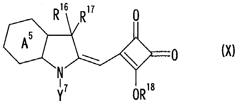
- ring A 5 represents the same group as ring A 1 in general formula (I)
- Y 7 represents the same group as Y 1 in general formula (I)
- R 16 represents the same group as R 1 in the general formula (I)
- R 17 represents the same group as R 2 in the general formula (I)
- R 18 represents a hydrogen atom.
- a child or an alkyl group having 1 to 8 carbon atoms is represented.
- the method for producing the cyanine compound of the present invention represented by the general formula (VI) or (VII) is not particularly limited, and can be obtained by a method using a known general reaction.
- a production method for example, a method of synthesizing an intermediate b force as in the route shown in the following [Chemical Formula 22] can be mentioned.
- the following [Chemical Formula 22] is the force indicating the production method of the cyanine compound represented by the general formula (VI).
- the cyanine compound represented by the general formula (VII) is It can manufacture according to a manufacturing method. [0057] [Chemical 22]
- the cyanine compound of the present invention described above is suitable as an optical element for light in the range of 500 nm to 700 nm, particularly as an optical element for light in the range of 550 to 620 nm.
- the optical element is an element that exhibits a function by absorbing specific light, and specifically includes a light absorber, an optical recording agent, a photosensitizer, and the like.
- the optical recording agent is used in an optical recording layer in an optical recording medium such as DV D-R
- the light absorber is a liquid crystal display (LCD), a plasma display panel (PDP), an electoric luminescence display (ELD). ), Cathode ray tube display (CRT), fluorescent display tube, field emission display, and other image display devices, or analysis devices, semiconductor device manufacturing, astronomical observation, optical communication, and other optical filters.
- the cyanine compound of the present invention not only has excellent optical properties and light stability, but also has a high extinction coefficient, and therefore has a feature that a small amount of addition is required, and has high solubility in organic solvents. It also has the feature. These features are advantageous for application to optical recording media and optical filters.
- a method of applying a solution obtained by dissolving an optical recording agent in an organic solvent by spin coating or spraying is generally used. Therefore, it is advantageous that the compound used as the optical recording agent has higher solubility in an organic solvent because the process margin for forming an optical recording layer is increased.
- a compound having a high solubility in an organic solvent has a good compatibility with a synthetic resin, so that it is necessary to uniformly disperse or dissolve the optical element in the synthetic resin. It is also advantageous for the production of filters.
- optical filter of the present invention containing the cyanine compound of the present invention will be described below.
- the optical filter of the present invention is used in an image display device, particularly for the image forming apparatus of the present invention.
- the amount of things, per unit area of the optical filter typically 1 ⁇ : LOOOmgZm 2, preferably 5: a LOOmgZm 2.
- LmgZm 2 When the amount is less than LmgZm 2, can not be sufficiently exhibited a light absorption effect, when used beyond LOOOmgZm 2, there is a possibility of lowering the display quality such color filter is strong no longer too and In addition, the brightness may decrease.
- the optical filter 1 of the present invention is usually disposed on the front surface of a display.
- the optical filter of the present invention can be applied to the front side (outside) or back side (display side) of the front plate when a front plate is provided in front of the display which can be directly attached to the surface of the display. You can also paste an optical filter.
- the optical filter of the present invention uses a light absorbent other than the cyanine compound of the present invention for color tone adjustment or the like, and reflects or reflects external light.
- a light absorber corresponding to 480 nm to 500 nm other than the cyanine compound of the present invention may be used.
- the image display device is a plasma display, use a near-infrared absorber that supports 750 to 1 lOOnm.
- Examples of the light absorber for color tone adjustment include trimethine indolium compounds, trimethine benzoxazolium compounds, trimethine benzothiazolium compounds, which are used for removing orange light at 550 to 600 nm.
- Trimethine cyanine derivatives such as: pentamethine cyanine derivatives such as pentamethine oxazolium compounds and pentamethine thiazolium compounds; squarylium dye derivatives; azomethine dye derivatives; xanthene dye derivatives; azo dye derivatives; pyromethene dyes Derivatives; azo metal complex derivatives: rhodamine dye derivatives; phthalocyanine derivatives; porphyrin derivatives; dipyrromethene metal chelate compounds.
- pentamethine cyanine derivatives such as pentamethine oxazolium compounds and pentamethine thiazolium compounds
- squarylium dye derivatives such as pentamethine cyanine derivatives such as pentamethine oxazolium compounds and pentamethine thiazolium compounds
- squarylium dye derivatives such as pentamethine cyan
- the above-mentioned light absorbing agent for 480 to 500 nm for preventing reflection of external light includes trimethine indolium compound, trimethine oxazolium compound, trimethine thiazolium compound, indolidene.
- trimethine cyanine derivatives such as trimethine thiazoum compounds; phthalocyanine derivatives; naphthalocyanine derivatives; porphyrin derivatives; dipyrromethene metal chelate compounds.
- infrared remote control malfunction prevention 750 ⁇ As a near infrared absorber for L lOOnm are pentamethine benzoinazolium compounds, pentamethine benzoinazolium compounds, pentamethine cyanine derivatives such as pentamethine benzothiazolium compounds; heptamethine indolium compounds, heptamethine benzoindolium compounds, heptamethine oxazolium compounds, Heptamethine cyanine derivatives such as heptamethine benzoxazolium compounds, heptamethine thiazolium compounds, heptamethine benzothiazolium compounds; squarylium derivatives; bis (stilbene dithiolato) compounds, bis (benzenedithiolato) nickel compounds, Nickel complexes such as bis (camphthiolato) nickel compounds; squarylium derivatives; azo dye derivatives;
- the light absorber for color tone adjustment, the light absorber corresponding to 480-50 Onm, and the near-infrared absorber are in the same layer as the cyanine compound of the present invention. It may be contained in another layer which may be contained.
- the amount used thereof is usually in the range of 1 to 1000 mgZm 2 per unit area of the optical filter, preferably 5 to: LOOmgZm 2 .
- a typical configuration of the optical filter of the present invention includes a transparent support provided with various layers such as an undercoat layer, an antireflection layer, a hard coat layer, and a lubricating layer as necessary.
- Examples of the method for allowing the optical filter of the present invention to include the optional components of the cyanine compound of the present invention, a light absorber that is a dye compound other than the cyanine compound of the present invention, and various stabilizers include, for example, (1) A transparent support or a method for inclusion in any layer, (2) a method for coating the transparent support or any layer, and (3) any two adjacent members selected from the transparent support and any layer. Examples thereof include a method of containing in the pressure-sensitive adhesive layer, and (4) a method of providing a light absorption layer containing a light absorber such as the cyanine compound of the present invention separately from the arbitrary layers.
- the cyanine compound according to the present invention is suitable for inclusion in the light-absorbing material by the force contained in the pressure-sensitive adhesive layer by the method (3) or the method (4).
- Examples of the material of the transparent support include, for example, inorganic materials such as glass; diacetyl cellulose mouthpiece, triacetinoresenorelose (TAC), propio-noresenorelose, butyrinoresenorelose
- inorganic materials such as glass
- diacetyl cellulose mouthpiece triacetinoresenorelose (TAC)
- TAC triacetinoresenorelose
- propio-noresenorelose propio-noresenorelose
- butyrinoresenorelose butyrinoresenorelose
- the transmittance of the transparent support is preferably 80% or more, and more preferably 86% or more.
- the haze is preferably 2% or less, more preferably 1% or less.
- an infrared absorber an ultraviolet absorber, a phenol-based antioxidant, a phosphorus-based antioxidant, a flame retardant, a lubricant, an antistatic agent, inorganic fine particles, and the like can be added.
- the transparent support can be subjected to various surface treatments.
- Examples of the inorganic fine particles include silicon dioxide, titanium dioxide, barium sulfate, calcium carbonate, talc, and kaolin.
- Examples of the various surface treatments include chemical treatment, mechanical treatment, corona discharge treatment, flame treatment, ultraviolet irradiation treatment, high frequency treatment, glow discharge treatment, active plasma treatment, laser treatment, mixed acid treatment. And ozone oxidation treatment.
- the undercoat layer is a layer used between the transparent support and the light absorption layer when a light absorption layer containing a light absorber is provided.
- the undercoat layer is a layer containing a polymer having a glass transition temperature of ⁇ 60 to 60 ° C., a layer having a rough surface on the light absorption layer side, or a layer containing a polymer having an affinity for the polymer of the light absorption layer.
- the undercoat layer is provided on the surface of the transparent support on which the light absorption layer is not provided, and the adhesive strength between the transparent support and the layer provided thereon (for example, an antireflection layer or a hard coat layer).
- the thickness of the undercoat layer is 2 ⁇ ! ⁇ 20 m is preferred 5 nm ⁇ 5 ⁇ m is more preferred 20 nm ⁇ 2 ⁇ m is more preferred 50 nm ⁇ l ⁇ m is still more preferred 80 ⁇ ! Most preferred is ⁇ 300 nm.
- An undercoat layer containing a polymer with a glass transition temperature of 60 to 60 ° C is a sticky polymer that bonds the transparent support to the filter layer. .
- Polymers having a glass transition temperature of 60 to 60 ° C include, for example, butyl chloride, vinylidene chloride, butyl acetate, butadiene, neoprene, styrene, black-prene, acrylic ester, methacrylic ester, acrylonitrile, or methyl vinyl ether. It can be obtained by polymerization or copolymerization thereof.
- the glass transition temperature is preferably 50 ° C or lower, more preferably 40 ° C or lower, more preferably 30 ° C or lower, and even more preferably 25 ° C or lower. Further, it is most preferably 20 ° C or less.
- the elastic modulus at 25 ° C of the undercoat layer is preferably 1 to 1000 MPa, more preferably 5 to 800 MPa, and even more preferably 10 to 500 MPa.
- the undercoat layer having a rough surface of the light absorption layer forms a light absorption layer on the rough surface, thereby bonding the transparent support and the light absorption layer.
- the undercoat layer having a rough surface of the light absorbing layer can be easily formed by applying a polymer latex.
- the average particle size of the latex is preferably 0.02 to 3 111, more preferably 0.05 to 1 / ⁇ ⁇ .
- the optical filter of the present invention may be provided with two or more undercoat layers.
- a solvent for swelling the transparent support a matting agent, a surfactant, an antistatic agent, a coating aid, a hardening agent, and the like may be added.
- a low refractive index layer is essential.
- the refractive index of the low refractive index layer is lower than the refractive index of the transparent support.
- the refractive index of the low refractive index layer is preferably 1.20 to L55, more preferably 1.30 to L50.
- the thickness of the low refractive index layer is preferably 50 to 400 nm, more preferably 50 to 200 nm.
- the low refractive index layer is a layer made of a fluorine-containing polymer having a low refractive index (Japanese Patent Laid-Open No. 57-34526, Japanese Patent Laid-Open No. 3-130103, Japanese Patent Laid-Open No. 6-115023, Japanese Patent Laid-Open No.
- layers obtained by the sol-gel method (described in JP-A-5-208811, JP-A-6-299091, JP-A-7-168003), or layers containing fine particles (Japanese Patent Publication No. 60) — 59250, JP-A-5-13021, JP-A-6-56478, JP-A-7-92306, and JP-A-9-288201).
- voids are formed in the low refractive index layer as micro voids between or within the fine particles. can do.
- the layer containing fine particles preferably has a porosity of 3 to 50% by volume, and more preferably has a porosity of 5 to 35% by volume.
- a layer having a high refractive index (medium'high refractive index layer) is laminated in addition to the low refractive index layer in the antireflection layer.
- the refractive index of the high refractive index layer is preferably 1.65-2.40, more preferably 1.70-2.20.
- the refractive index of the middle refractive index layer is adjusted to be an intermediate value between the refractive index of the low refractive index layer and the refractive index of the high refractive index layer.
- the refractive index of the middle refractive index layer is preferably 1.50 to L90, more preferably 1.55 to L70.
- the thickness of the medium / high refractive index layer is preferably 5 ⁇ to 100 / ⁇ ⁇ , more preferably 10 ⁇ to 10 / ⁇ m, and most preferably 30 ⁇ to 1 / ⁇ ⁇ . preferable.
- the haze of the medium / high refractive index layer is preferably 5% or less, more preferably 3% or less, and even more preferably 1% or less.
- the middle / high refractive index layer can be formed using a polymer binder having a relatively high refractive index.
- Polymers having other cyclic (aromatic, heterocyclic, and alicyclic) groups and polymers having a non-fluorine atom or a rogen atom as a substituent also have a high refractive index. You may use the polymer formed by the polymerization reaction of the monomer which introduce
- inorganic fine particles may be dispersed in the polymer binder.
- the refractive index of the inorganic fine particles is preferably 1.80 to 2.80. It is preferable that the inorganic fine particles form a metal oxide or sulfate.
- metal oxides or sulfides include titanium oxide (eg, rutile, rutile-anatase mixed crystal, anatase, amorphous structure), tin oxide, indium oxide, zinc oxide, zirconium oxide, zinc sulfate. Etc.
- titanium oxide, tin oxide, and indium oxide are particularly preferable.
- the inorganic fine particles are mainly composed of oxides or sulfides of these metals, and can further contain other elements.
- the main component means the component having the highest content (% by weight) among the components constituting the particles.
- Other elements include Ti, Zr, Sn, Sb, Cu, Fe, Examples include Mn, Pb, Cd, As, Cr, Hg, Zn, Al, Mg, Si, P, and S.
- the surface of the antireflection layer can be provided with an antiglare function (function of scattering incident light on the surface and preventing the scenery around the film from moving to the film surface).
- an antiglare function function of scattering incident light on the surface and preventing the scenery around the film from moving to the film surface.
- An antireflection layer having an antiglare function can be obtained.
- An antireflection layer having an antiglare function generally has a haze of 3 to 30%.
- the hard coat layer has a hardness higher than that of the transparent support.
- the hard coat layer preferably contains a crosslinked polymer.
- the hard coat layer can be formed using an acrylic, urethane, or epoxy polymer, oligomer, or monomer (for example, an ultraviolet curable resin). Silica-based material strength can also be achieved by forming a hard coat layer.
- a lubricating layer may be formed on the surface of the antireflection layer (low refractive index layer).
- the lubricating layer has a function of imparting slipperiness to the surface of the low refractive index layer and improving scratch resistance.
- the lubricating layer can be formed using polyorganosiloxane (for example, silicon oil), natural wax, petroleum wax, higher fatty acid metal salt, fluorine-based lubricant or derivative thereof.
- the thickness of the lubricating layer is preferably 2 to 20 nm.
- the above-mentioned "(3) Method for containing in an adhesive layer between any two adjacent members selected from the transparent support and any layer" In the case of adopting the above, after the cyanine compound of the present invention is contained in the pressure-sensitive adhesive, the adjacent two of the above-mentioned transparent support and arbitrary layers may be bonded using the pressure-sensitive adhesive.
- the pressure-sensitive adhesive known transparent adhesives for laminated glass such as silicone-based, urethane-based and acrylic-based resin adhesives, polybutyral adhesives, and ethylene-vinyl acetate-based adhesives can be used.
- a metal chelate-based, isocyanate-based, epoxy-based or the like crosslinking agent may be used as a curing agent. You can.
- the thickness of the pressure-sensitive adhesive layer is preferably 2 to 400 / ⁇ ⁇ .
- the cyanine compound of the present invention contains: It can be used as it is to form a light absorption layer, or it can be dispersed in a binder to form a light absorption layer.
- binder examples include natural polymer materials such as gelatin, casein, starch, cellulose derivatives, and alginic acid, or polymethyl methacrylate, polybutyl petital, polybulur pyrrolidone, polybulal alcohol, polyvinyl chloride- Synthetic polymer materials such as rubber, styrene butadiene copolymer, polystyrene, polycarbonate, and polyamide are used.
- natural polymer materials such as gelatin, casein, starch, cellulose derivatives, and alginic acid, or polymethyl methacrylate, polybutyl petital, polybulur pyrrolidone, polybulal alcohol, polyvinyl chloride- Synthetic polymer materials such as rubber, styrene butadiene copolymer, polystyrene, polycarbonate, and polyamide are used.
- an organic solvent can be used at the same time.
- the organic solvent is not particularly limited, and various known solvents can be appropriately used.
- isopropanol Alcohols such as methyl solvate, cetyl sorb, butyl solvol, butyl diglycol, etc .
- Ketones such as acetone, methyl ethyl ketone, methyl isobutyl ketone, cyclohexanone, diacetone alcohol, acetic acid Esters such as ethyl acetate, butyl acetate and methoxyethyl acetate
- acrylic acid esters such as ethyl acrylate and butyl acrylate
- fluorinated alcohols such as 2, 2, 3, 3-tetrafluoropropanol
- Hydrocarbons such as hexane, benzene, toluene, xylene; methylene dichloride, dichloro Tan, chlorinated hydrocarbons such as black hole
- the undercoat layer, antireflection layer, hard coat layer, lubricating layer, light absorption layer and the like can be formed by a general coating method.
- Application methods include dip coating, air knife coating, curtain coating, roller coating, wire bar coating, gravure coating, and etatrusion coating using a hopper (described in US Pat. No. 2681 294) ) And the like.
- Two or more layers may be formed by simultaneous application.
- an optical recording medium having an optical recording layer formed on a substrate is used for the optical recording layer.
- the optical recording material of the present invention containing the cyanine compound of the present invention will be described below.
- the cyanine compound of the present invention represented by the general formula (I) or (V) is used for an optical recording layer in an optical recording medium for recording information by applying information as a thermal information pattern by a laser or the like. It is also useful for optical recording materials used for optical recording layers such as DVD-R and DVD + R.
- the optical recording material of the present invention is a material used for forming an optical recording layer, and the cyanine compound of the present invention represented by the general formula (I) or (V) and the general formula ( It is a mixture of the cyanine compound of the present invention represented by I) or (V) and an organic solvent or various compounds described later.
- a method for forming the optical recording layer of the optical recording medium generally, lower alcohols such as methanol and ethanol; ether alcohols such as methyl caffeosolve, ethylcethylsolve solve, butylcectosolve and butyldiglycol are used.
- lower alcohols such as methanol and ethanol
- ether alcohols such as methyl caffeosolve, ethylcethylsolve solve, butylcectosolve and butyldiglycol are used.
- Ketones such as acetone, methyl ethyl ketone, methyl isobutyl ketone, cyclohexanone and diacetone alcohol, esters such as ethyl acetate, butyl acetate and methoxyethyl acetate; acrylics such as ethyl acrylate and butyl acrylate Acid esters, fluorinated alcohols such as 2, 2, 3, 3-tetrafluoropropanol; hydrocarbons such as benzene, toluene, xylene; chlorination of methylene dichloride, dichloroethane, chloroform, etc.
- the cyanine compound and various compounds of the present invention are dissolved in an organic solvent such as hydrocarbons.
- the solution on the substrate, spin coating, spray one, wet coating is applied by Deitsubingu etc., evaporation, and sputtering method, etc.
- the thickness of the optical recording layer is usually 0.001 to 10 / ⁇ ⁇ , preferably 0.01 to 5 m.
- the content of the cyanine compound of the present invention in the optical recording material of the present invention is preferably 10 to L00% by weight in the solid content contained in the optical recording material of the present invention.
- the optical recording material of the present invention may contain other cyanine compounds, azo compounds, phthalocyanine compounds, oxonol compounds, squarylium compounds, styryl compounds as necessary.
- optical recording layer such as compounds and rhodamine compounds; resins such as polyethylene, polyester, polystyrene and polycarbonate; surfactants; antistatic agents; lubricants; flame retardants; radical scavengers such as hindered amines; It may contain a pit formation accelerator such as a phthalene derivative; a dispersant; an antioxidant; a cross-linking agent; Furthermore, the optical recording material of the present invention includes
- a reflective film can be formed by vapor deposition or sputtering using gold, silver, aluminum, copper or the like, acrylic resin, ultraviolet curable resin, or the like.
- a protective layer can also be formed with fat or the like.
- a nitrogen-substituted reaction flask was charged with 0.90 g (l.4 mmol) of Compound No. 50 obtained in Example 3, acetic acid 3. Og and water 1. Og, and heated at 110 ° C. for 9 hours. After cooling to room temperature, the reaction solution was concentrated to dryness under reduced pressure, 10 g of black mouth form was added to the residue twice, the oil layer was separated, and washed with water. Dehydration with anhydrous sodium sulfate and desolvation were carried out to obtain 0.53 g (crude yield 65%) of a brown amorphous substance. The obtained brown amorphous substance was subjected to NMR analysis, and it was confirmed that the brown amorphous substance was Compound No. 49, which was the target product. The NMR analysis results are shown below.
- a nitrogen-substituted reaction flask was charged with 0.5 3 g (0.88 mmol) of the crude product of Compound No. 50 obtained in Example 4, 0.12 g (0.88 mmol) of 1-methinolein donole, and 1.9 g of butanol.
- the obtained copper-colored amorphous substance was confirmed to be the target compound No. 2.
- the analysis results for the obtained copper-colored amorphous material are shown below.
- UV absorption measurement black mouth form solvent
- a 1% by mass solution of cyanine compound shown in Table 2 was prepared. Using these solutions, spin coating was performed on a polycarbonate plate of 20 20111111 at 2000 to 111 for 60 seconds to prepare test pieces.
- test piece was prepared in the same manner as in Comparative Example 4 and 55,000 lux was applied to the test piece.
- the following composition was melt-kneaded for 5 minutes at 260 ° C with a plast mill. After kneading, a dye-containing pellet was obtained with a nozzle force extrusion water cooled pelletizer having a diameter of 6 mm. This pellet was formed into a thin plate having a thickness of 0.25 mm at 250 ° C. using an electric press. When this thin plate was measured with a spectrophotometer U-3010 manufactured by Hitachi, Ltd., the ⁇ max force was 642 m and the half width was 25 nm.
- a UV varnish was prepared according to the following composition, and the UV varnish was applied to a 188 micron thick polyethylene terephthalate film subjected to easy adhesion treatment with a bar coater # 9 and then dried at 80 ° C. for 30 seconds. After that, ultraviolet rays were irradiated with lOOmJ with a high-pressure mercury lamp with an infrared cut film filter to obtain a film with a cured film thickness of about 5 microns. When this was measured with Hitachi Ltd. Spectrophotometer U-3010, the maximum force was 641 nm and the half-value width was 25 nm.
- a test piece was prepared using Compound No. 2 in the same manner as in Evaluation Example 2 described above.
- the absorption UV spectrum of the thin film and the UV spectrum of the reflected light at an incident angle of 5 ° were measured, and the absorption max was 617 nm and the reflected light max was 644 nm.
- the cyanine compound of the present invention is excellent in solubility and light resistance.
- the cyanine compound of the present invention has a high molar extinction coefficient (Examples 5 to 7), and is clearly suitable for optical filters and optical recording materials. It is clear from Examples 3-6.
- a novel cyan compound having excellent solubility and light resistance suitable as an optical element can be provided.
- An optical filter using the cyanine compound is suitable as an optical filter for image display, and an optical recording material containing the cyanine compound is used for forming an optical recording layer of an optical recording medium. Preferably used.
Landscapes
- Chemical & Material Sciences (AREA)
- Organic Chemistry (AREA)
- Physics & Mathematics (AREA)
- General Physics & Mathematics (AREA)
- Optics & Photonics (AREA)
- Optical Filters (AREA)
- Indole Compounds (AREA)
- Thermal Transfer Or Thermal Recording In General (AREA)
- Optical Record Carriers And Manufacture Thereof (AREA)
- Nitrogen Condensed Heterocyclic Rings (AREA)
- Plural Heterocyclic Compounds (AREA)
Description


Claims


Priority Applications (5)
| Application Number | Priority Date | Filing Date | Title |
|---|---|---|---|
| KR1020077021211A KR101272742B1 (ko) | 2005-04-05 | 2006-04-04 | 시아닌화합물, 광학필터 및 광학기록재료 |
| CN2006800106067A CN101151331B (zh) | 2005-04-05 | 2006-04-04 | 花青化合物、滤光器和光学记录材料 |
| EP06731041.7A EP1867682B1 (en) | 2005-04-05 | 2006-04-04 | Cyanine compounds, optical filters and optical recording materials |
| US11/886,626 US7745632B2 (en) | 2005-04-05 | 2006-04-04 | Cyanine compounds, optical filters, and optical recording materials |
| US12/764,439 US8193366B2 (en) | 2005-04-05 | 2010-04-21 | Cyanine compounds |
Applications Claiming Priority (4)
| Application Number | Priority Date | Filing Date | Title |
|---|---|---|---|
| JP2005-108339 | 2005-04-05 | ||
| JP2005108339 | 2005-04-05 | ||
| JP2006004215A JP4986457B2 (ja) | 2005-04-05 | 2006-01-11 | シアニン化合物、光学フィルター及び光学記録材料 |
| JP2006-004215 | 2006-01-11 |
Related Child Applications (2)
| Application Number | Title | Priority Date | Filing Date |
|---|---|---|---|
| US11/886,626 A-371-Of-International US7745632B2 (en) | 2005-04-05 | 2006-04-04 | Cyanine compounds, optical filters, and optical recording materials |
| US12/764,439 Division US8193366B2 (en) | 2005-04-05 | 2010-04-21 | Cyanine compounds |
Publications (1)
| Publication Number | Publication Date |
|---|---|
| WO2006109618A1 true WO2006109618A1 (ja) | 2006-10-19 |
Family
ID=37086896
Family Applications (1)
| Application Number | Title | Priority Date | Filing Date |
|---|---|---|---|
| PCT/JP2006/307093 Ceased WO2006109618A1 (ja) | 2005-04-05 | 2006-04-04 | シアニン化合物、光学フィルター及び光学記録材料 |
Country Status (7)
| Country | Link |
|---|---|
| US (2) | US7745632B2 (ja) |
| EP (1) | EP1867682B1 (ja) |
| JP (1) | JP4986457B2 (ja) |
| KR (1) | KR101272742B1 (ja) |
| CN (1) | CN101151331B (ja) |
| TW (1) | TW200708567A (ja) |
| WO (1) | WO2006109618A1 (ja) |
Cited By (5)
| Publication number | Priority date | Publication date | Assignee | Title |
|---|---|---|---|---|
| WO2008123404A1 (ja) * | 2007-03-30 | 2008-10-16 | Adeka Corporation | シアニン化合物、該化合物を用いた光学フィルター及び光学記録材料 |
| US20120197026A1 (en) * | 2010-01-15 | 2012-08-02 | Adeka Corporation | Color tone correcting agent, squarylium compound and optical filter |
| US8247577B2 (en) * | 2006-05-23 | 2012-08-21 | Adeka Corporation | Optical recording material and cyanine compound |
| EP2003171B1 (en) * | 2006-03-31 | 2014-09-03 | Adeka Corporation | Cyanine compound and optical recording material |
| WO2019167930A1 (ja) * | 2018-02-28 | 2019-09-06 | 富士フイルム株式会社 | 樹脂組成物、光学フィルター、画像表示装置、固体撮像素子、及び化合物 |
Families Citing this family (16)
| Publication number | Priority date | Publication date | Assignee | Title |
|---|---|---|---|---|
| KR101099292B1 (ko) * | 2004-07-29 | 2011-12-26 | 가부시키가이샤 아데카 | 광학 기록 재료 및 광학 기록 매체 |
| JP4688480B2 (ja) * | 2004-11-25 | 2011-05-25 | 株式会社Adeka | シアニン化合物、該化合物を用いた光学記録材料、及び光学記録媒体 |
| JP5100635B2 (ja) * | 2006-03-31 | 2012-12-19 | 株式会社Adeka | インドリウム化合物及び光学記録材料 |
| JP5913776B2 (ja) * | 2008-05-27 | 2016-04-27 | 株式会社Adeka | 色補正材料、フィルム形成用組成物及び光学フィルター |
| KR101236035B1 (ko) * | 2008-09-30 | 2013-02-21 | 가부시키가이샤 아데카 | 광전 변환 소자용 색소 및 광전 변환 소자 |
| JP5519681B2 (ja) * | 2008-10-27 | 2014-06-11 | ソニー株式会社 | アシロイン基が付着した発色団を含む色素 |
| CN101709150A (zh) * | 2009-08-14 | 2010-05-19 | 上海拓引数码技术有限公司 | 一种花菁类光记录媒体染料 |
| KR101117209B1 (ko) | 2009-10-12 | 2012-03-19 | 경북대학교 산학협력단 | 벤조티아졸계 세미스쿠아릴리움 염료 및 이를 이용한 수은 금속 이온 검출방법 |
| CN101787218B (zh) * | 2010-01-15 | 2014-04-02 | 大连理工大学 | 一类共轭链上β-位氮取代五甲川菁类荧光染料 |
| WO2011162393A1 (ja) * | 2010-06-25 | 2011-12-29 | 旭硝子株式会社 | 光学フィルムとその製造方法 |
| EP2613610A4 (en) | 2010-09-03 | 2015-05-20 | Adeka Corp | COLOR CONVERSION FILTER |
| JP2014126642A (ja) * | 2012-12-26 | 2014-07-07 | Adeka Corp | 波長カットフィルタ |
| CN106772746B (zh) * | 2016-12-26 | 2023-05-05 | 信阳舜宇光学有限公司 | 红外截止滤光片及其制备方法 |
| JP7199998B2 (ja) * | 2018-02-26 | 2023-01-06 | 住友化学株式会社 | 化合物及び着色樹脂組成物 |
| WO2020045199A1 (ja) * | 2018-08-31 | 2020-03-05 | Dic株式会社 | ハロゲン化亜鉛フタロシアニン顔料、着色組成物及びカラーフィルタ |
| WO2025142714A1 (ja) * | 2023-12-25 | 2025-07-03 | 株式会社日本触媒 | 樹脂組成物、その製造方法、その用途、成形体の製造方法、及び、撮像素子の製造方法 |
Citations (38)
| Publication number | Priority date | Publication date | Assignee | Title |
|---|---|---|---|---|
| US2681294A (en) | 1951-08-23 | 1954-06-15 | Eastman Kodak Co | Method of coating strip material |
| US2761791A (en) | 1955-02-23 | 1956-09-04 | Eastman Kodak Co | Method of multiple coating |
| US2941898A (en) | 1957-12-16 | 1960-06-21 | Ilford Ltd | Production of multilayer photographic materials |
| US3508947A (en) | 1968-06-03 | 1970-04-28 | Eastman Kodak Co | Method for simultaneously applying a plurality of coated layers by forming a stable multilayer free-falling vertical curtain |
| US3526528A (en) | 1965-10-28 | 1970-09-01 | Fuji Photo Film Co Ltd | Multiple doctor coating process and apparatus |
| JPS5734526A (en) | 1980-08-11 | 1982-02-24 | Seiko Epson Corp | Liquid crystal display cell |
| JPS6059250A (ja) | 1983-09-08 | 1985-04-05 | 大根 弘行 | 防湿養生シ−ト及びその施行法 |
| JPS60234892A (ja) | 1984-05-08 | 1985-11-21 | Tdk Corp | 光記録媒体 |
| JPS61126555A (ja) * | 1984-11-26 | 1986-06-14 | Canon Inc | 電子写真感光体 |
| JPH01208118A (ja) | 1987-12-15 | 1989-08-22 | General Electric Co <Ge> | 連続長のマルチフィラメントおよびマルチファイバ構造物を含浸するための装置および方法 |
| JPH0513021A (ja) | 1991-07-05 | 1993-01-22 | Hitachi Ltd | 反射防止体及びその利用装置 |
| JPH0543814A (ja) | 1990-11-30 | 1993-02-23 | Teijin Ltd | イオウ化合物が配位した有機色素、有機色素組成物及び光記録媒体 |
| JPH05208811A (ja) | 1992-01-29 | 1993-08-20 | Central Glass Co Ltd | フッ化マグネシウムオルガノゾル溶液の製造方法とこの溶液による膜の形成方法 |
| JPH05305770A (ja) | 1992-04-28 | 1993-11-19 | Ricoh Co Ltd | 光情報記録媒体 |
| JPH0656478A (ja) | 1992-07-31 | 1994-03-01 | Sumitomo Cement Co Ltd | 複合機能材 |
| JPH06115023A (ja) | 1992-10-07 | 1994-04-26 | Asahi Glass Co Ltd | 反射防止性フィルム |
| JPH06239028A (ja) | 1993-02-17 | 1994-08-30 | Canon Inc | 光記録媒体およびその製造方法 |
| JPH06299091A (ja) | 1993-04-13 | 1994-10-25 | Asahi Optical Co Ltd | 反射防止膜形成用コーティング組成物 |
| JPH0792306A (ja) | 1993-09-24 | 1995-04-07 | Dainippon Printing Co Ltd | ハード性を有する高屈折率膜、反射防止フィルム及びその製造方法 |
| JPH0796334A (ja) | 1993-09-28 | 1995-04-11 | Miyamae:Kk | 湾曲ベント管の製造方法及びそれに用いる製造装置 |
| JPH07168003A (ja) | 1993-10-18 | 1995-07-04 | Asahi Glass Co Ltd | 反射防止層を有する光学物品 |
| JPH07168004A (ja) | 1993-11-24 | 1995-07-04 | Seiko Epson Corp | 反射防止膜の形成方法 |
| JPH08313702A (ja) | 1995-05-12 | 1996-11-29 | Nippon Kayaku Co Ltd | 反射防止体およびその製造方法 |
| JPH09288201A (ja) | 1995-12-07 | 1997-11-04 | Fuji Photo Film Co Ltd | 反射防止膜及びそれを用いた画像表示装置 |
| JPH09309886A (ja) | 1996-03-21 | 1997-12-02 | Sumitomo Seika Chem Co Ltd | 置換ベンゼンジチオール金属錯体およびその製造方法 |
| JPH09323478A (ja) | 1996-06-06 | 1997-12-16 | Tdk Corp | 光記録媒体 |
| JPH1045767A (ja) | 1996-07-31 | 1998-02-17 | Sumitomo Seika Chem Co Ltd | 置換ベンゼンジチオール金属錯体およびその製法 |
| WO1998029257A1 (fr) | 1996-12-27 | 1998-07-09 | Tdk Corporation | Support d'enregistrement optique |
| JP2000168237A (ja) | 1998-12-07 | 2000-06-20 | Tdk Corp | 光記録媒体 |
| JP3130103B2 (ja) | 1991-12-26 | 2001-01-31 | 東レ・ダウコーニング・シリコーン株式会社 | アルミニウムダイキヤスト用離型剤組成物 |
| JP2001047740A (ja) * | 1999-08-04 | 2001-02-20 | Asahi Denka Kogyo Kk | 光学記録材料 |
| JP2002201373A (ja) | 2000-10-27 | 2002-07-19 | Hayashibara Biochem Lab Inc | 耐光性改善剤 |
| JP2002206061A (ja) | 2000-07-05 | 2002-07-26 | Hayashibara Biochem Lab Inc | スチリル色素 |
| JP2003171571A (ja) | 2001-09-28 | 2003-06-20 | Tamura Kaken Co Ltd | シアニン系化合物、その中間体、シアニン系色素、光学記録材料及び光情報記録媒体 |
| JP2004195765A (ja) * | 2002-12-18 | 2004-07-15 | Taiyo Yuden Co Ltd | 光情報記録媒体 |
| JP2004281024A (ja) | 2003-03-18 | 2004-10-07 | United Memories Inc | 集積回路メモリをリフレッシュするための回路および方法、ならびに集積回路メモリのためのリフレッシュ回路 |
| JP2005297407A (ja) | 2004-04-13 | 2005-10-27 | Toshiba Corp | 追記型情報記録媒体 |
| WO2006035555A1 (ja) * | 2004-09-28 | 2006-04-06 | Adeka Corporation | シアニン化合物、光学フィルター及び光学記録材料 |
Family Cites Families (6)
| Publication number | Priority date | Publication date | Assignee | Title |
|---|---|---|---|---|
| JPH06263732A (ja) * | 1993-03-12 | 1994-09-20 | Mitsubishi Kasei Corp | シクロブテン系化合物,その製法並びにスクアリリウム系化合物の製造法 |
| US20030224293A1 (en) * | 1999-08-04 | 2003-12-04 | Asahi Denka Kogyo Kabushiki Kaisha | Optical recording material |
| JP4183918B2 (ja) * | 2001-02-14 | 2008-11-19 | 株式会社リコー | 光記録媒体及びこれを用いる光記録方法 |
| JP2004099713A (ja) * | 2002-09-09 | 2004-04-02 | Sumitomo Chem Co Ltd | 非対称スクアリリウム化合物、及び該化合物を含む映像表示機器用フィルター |
| JP5004506B2 (ja) * | 2005-06-24 | 2012-08-22 | 株式会社Adeka | 光学フィルター |
| JP5078877B2 (ja) * | 2006-03-31 | 2012-11-21 | 株式会社Adeka | シアニン化合物及び光学記録材料 |
-
2006
- 2006-01-11 JP JP2006004215A patent/JP4986457B2/ja not_active Expired - Fee Related
- 2006-04-04 CN CN2006800106067A patent/CN101151331B/zh not_active Expired - Fee Related
- 2006-04-04 US US11/886,626 patent/US7745632B2/en not_active Expired - Fee Related
- 2006-04-04 TW TW095112022A patent/TW200708567A/zh not_active IP Right Cessation
- 2006-04-04 EP EP06731041.7A patent/EP1867682B1/en not_active Expired - Lifetime
- 2006-04-04 WO PCT/JP2006/307093 patent/WO2006109618A1/ja not_active Ceased
- 2006-04-04 KR KR1020077021211A patent/KR101272742B1/ko not_active Expired - Fee Related
-
2010
- 2010-04-21 US US12/764,439 patent/US8193366B2/en not_active Expired - Fee Related
Patent Citations (38)
| Publication number | Priority date | Publication date | Assignee | Title |
|---|---|---|---|---|
| US2681294A (en) | 1951-08-23 | 1954-06-15 | Eastman Kodak Co | Method of coating strip material |
| US2761791A (en) | 1955-02-23 | 1956-09-04 | Eastman Kodak Co | Method of multiple coating |
| US2941898A (en) | 1957-12-16 | 1960-06-21 | Ilford Ltd | Production of multilayer photographic materials |
| US3526528A (en) | 1965-10-28 | 1970-09-01 | Fuji Photo Film Co Ltd | Multiple doctor coating process and apparatus |
| US3508947A (en) | 1968-06-03 | 1970-04-28 | Eastman Kodak Co | Method for simultaneously applying a plurality of coated layers by forming a stable multilayer free-falling vertical curtain |
| JPS5734526A (en) | 1980-08-11 | 1982-02-24 | Seiko Epson Corp | Liquid crystal display cell |
| JPS6059250A (ja) | 1983-09-08 | 1985-04-05 | 大根 弘行 | 防湿養生シ−ト及びその施行法 |
| JPS60234892A (ja) | 1984-05-08 | 1985-11-21 | Tdk Corp | 光記録媒体 |
| JPS61126555A (ja) * | 1984-11-26 | 1986-06-14 | Canon Inc | 電子写真感光体 |
| JPH01208118A (ja) | 1987-12-15 | 1989-08-22 | General Electric Co <Ge> | 連続長のマルチフィラメントおよびマルチファイバ構造物を含浸するための装置および方法 |
| JPH0543814A (ja) | 1990-11-30 | 1993-02-23 | Teijin Ltd | イオウ化合物が配位した有機色素、有機色素組成物及び光記録媒体 |
| JPH0513021A (ja) | 1991-07-05 | 1993-01-22 | Hitachi Ltd | 反射防止体及びその利用装置 |
| JP3130103B2 (ja) | 1991-12-26 | 2001-01-31 | 東レ・ダウコーニング・シリコーン株式会社 | アルミニウムダイキヤスト用離型剤組成物 |
| JPH05208811A (ja) | 1992-01-29 | 1993-08-20 | Central Glass Co Ltd | フッ化マグネシウムオルガノゾル溶液の製造方法とこの溶液による膜の形成方法 |
| JPH05305770A (ja) | 1992-04-28 | 1993-11-19 | Ricoh Co Ltd | 光情報記録媒体 |
| JPH0656478A (ja) | 1992-07-31 | 1994-03-01 | Sumitomo Cement Co Ltd | 複合機能材 |
| JPH06115023A (ja) | 1992-10-07 | 1994-04-26 | Asahi Glass Co Ltd | 反射防止性フィルム |
| JPH06239028A (ja) | 1993-02-17 | 1994-08-30 | Canon Inc | 光記録媒体およびその製造方法 |
| JPH06299091A (ja) | 1993-04-13 | 1994-10-25 | Asahi Optical Co Ltd | 反射防止膜形成用コーティング組成物 |
| JPH0792306A (ja) | 1993-09-24 | 1995-04-07 | Dainippon Printing Co Ltd | ハード性を有する高屈折率膜、反射防止フィルム及びその製造方法 |
| JPH0796334A (ja) | 1993-09-28 | 1995-04-11 | Miyamae:Kk | 湾曲ベント管の製造方法及びそれに用いる製造装置 |
| JPH07168003A (ja) | 1993-10-18 | 1995-07-04 | Asahi Glass Co Ltd | 反射防止層を有する光学物品 |
| JPH07168004A (ja) | 1993-11-24 | 1995-07-04 | Seiko Epson Corp | 反射防止膜の形成方法 |
| JPH08313702A (ja) | 1995-05-12 | 1996-11-29 | Nippon Kayaku Co Ltd | 反射防止体およびその製造方法 |
| JPH09288201A (ja) | 1995-12-07 | 1997-11-04 | Fuji Photo Film Co Ltd | 反射防止膜及びそれを用いた画像表示装置 |
| JPH09309886A (ja) | 1996-03-21 | 1997-12-02 | Sumitomo Seika Chem Co Ltd | 置換ベンゼンジチオール金属錯体およびその製造方法 |
| JPH09323478A (ja) | 1996-06-06 | 1997-12-16 | Tdk Corp | 光記録媒体 |
| JPH1045767A (ja) | 1996-07-31 | 1998-02-17 | Sumitomo Seika Chem Co Ltd | 置換ベンゼンジチオール金属錯体およびその製法 |
| WO1998029257A1 (fr) | 1996-12-27 | 1998-07-09 | Tdk Corporation | Support d'enregistrement optique |
| JP2000168237A (ja) | 1998-12-07 | 2000-06-20 | Tdk Corp | 光記録媒体 |
| JP2001047740A (ja) * | 1999-08-04 | 2001-02-20 | Asahi Denka Kogyo Kk | 光学記録材料 |
| JP2002206061A (ja) | 2000-07-05 | 2002-07-26 | Hayashibara Biochem Lab Inc | スチリル色素 |
| JP2002201373A (ja) | 2000-10-27 | 2002-07-19 | Hayashibara Biochem Lab Inc | 耐光性改善剤 |
| JP2003171571A (ja) | 2001-09-28 | 2003-06-20 | Tamura Kaken Co Ltd | シアニン系化合物、その中間体、シアニン系色素、光学記録材料及び光情報記録媒体 |
| JP2004195765A (ja) * | 2002-12-18 | 2004-07-15 | Taiyo Yuden Co Ltd | 光情報記録媒体 |
| JP2004281024A (ja) | 2003-03-18 | 2004-10-07 | United Memories Inc | 集積回路メモリをリフレッシュするための回路および方法、ならびに集積回路メモリのためのリフレッシュ回路 |
| JP2005297407A (ja) | 2004-04-13 | 2005-10-27 | Toshiba Corp | 追記型情報記録媒体 |
| WO2006035555A1 (ja) * | 2004-09-28 | 2006-04-06 | Adeka Corporation | シアニン化合物、光学フィルター及び光学記録材料 |
Non-Patent Citations (1)
| Title |
|---|
| See also references of EP1867682A4 |
Cited By (9)
| Publication number | Priority date | Publication date | Assignee | Title |
|---|---|---|---|---|
| EP2003171B1 (en) * | 2006-03-31 | 2014-09-03 | Adeka Corporation | Cyanine compound and optical recording material |
| US8247577B2 (en) * | 2006-05-23 | 2012-08-21 | Adeka Corporation | Optical recording material and cyanine compound |
| WO2008123404A1 (ja) * | 2007-03-30 | 2008-10-16 | Adeka Corporation | シアニン化合物、該化合物を用いた光学フィルター及び光学記録材料 |
| US8958165B2 (en) | 2007-03-30 | 2015-02-17 | Adeka Corporation | Cyanine compound and optical filter and optical recording material containing same |
| US20120197026A1 (en) * | 2010-01-15 | 2012-08-02 | Adeka Corporation | Color tone correcting agent, squarylium compound and optical filter |
| US8759540B2 (en) * | 2010-01-15 | 2014-06-24 | Adeka Corporation | Color tone correcting agent, squarylium compound and optical filter |
| WO2019167930A1 (ja) * | 2018-02-28 | 2019-09-06 | 富士フイルム株式会社 | 樹脂組成物、光学フィルター、画像表示装置、固体撮像素子、及び化合物 |
| JPWO2019167930A1 (ja) * | 2018-02-28 | 2020-12-17 | 富士フイルム株式会社 | 樹脂組成物、光学フィルター、画像表示装置、固体撮像素子、及び化合物 |
| US12049556B2 (en) | 2018-02-28 | 2024-07-30 | Fujifilm Corporation | Resin composition, optical filter, image display device, solid-state imaging element, and compound |
Also Published As
| Publication number | Publication date |
|---|---|
| EP1867682B1 (en) | 2014-04-02 |
| US20100204474A1 (en) | 2010-08-12 |
| US8193366B2 (en) | 2012-06-05 |
| TW200708567A (en) | 2007-03-01 |
| US7745632B2 (en) | 2010-06-29 |
| JP4986457B2 (ja) | 2012-07-25 |
| US20080207918A1 (en) | 2008-08-28 |
| KR101272742B1 (ko) | 2013-06-10 |
| KR20070117594A (ko) | 2007-12-12 |
| CN101151331A (zh) | 2008-03-26 |
| EP1867682A4 (en) | 2010-10-27 |
| TWI375702B (ja) | 2012-11-01 |
| JP2006312710A (ja) | 2006-11-16 |
| EP1867682A1 (en) | 2007-12-19 |
| CN101151331B (zh) | 2012-10-31 |
Similar Documents
| Publication | Publication Date | Title |
|---|---|---|
| US8193366B2 (en) | Cyanine compounds | |
| KR101676384B1 (ko) | 시아닌 화합물을 이용한 근적외선 흡수재료 및 시아닌 화합물 | |
| CN102575107A (zh) | 色调修正剂、方酸内鎓盐化合物及滤光器 | |
| CN101008688B (zh) | 滤光器 | |
| JP2004315789A (ja) | シアニン化合物、光学フィルター及び光学記録材料 | |
| CN101437903B (zh) | 化合物、使用了该化合物的滤光器及光学记录材料 | |
| JP4979384B2 (ja) | シアニン化合物、光学フィルター及び光学記録材料 | |
| JP2007219114A (ja) | 光学フィルター | |
| CN101238100B (zh) | 吲哚化合物、滤光器以及光学记录材料 | |
| JP5501716B2 (ja) | シアニン化合物、該化合物を用いた光学記録材料及び色補正材料 | |
| JP4502791B2 (ja) | 光学フィルター | |
| JP4901188B2 (ja) | シアニン化合物及び該シアニン化合物を用いた光学フィルター | |
| JP4912010B2 (ja) | ジオキシノン構造を有する化合物並びに該化合物を用いた光学フィルター及び光学記録材料 | |
| CN101519414B (zh) | 花青化合物以及使用该化合物的滤光器 |
Legal Events
| Date | Code | Title | Description |
|---|---|---|---|
| WWE | Wipo information: entry into national phase |
Ref document number: 200680010606.7 Country of ref document: CN |
|
| 121 | Ep: the epo has been informed by wipo that ep was designated in this application | ||
| WWE | Wipo information: entry into national phase |
Ref document number: 2006731041 Country of ref document: EP Ref document number: 1020077021211 Country of ref document: KR |
|
| WWE | Wipo information: entry into national phase |
Ref document number: 11886626 Country of ref document: US |
|
| NENP | Non-entry into the national phase |
Ref country code: DE |
|
| NENP | Non-entry into the national phase |
Ref country code: RU |
|
| WWP | Wipo information: published in national office |
Ref document number: 2006731041 Country of ref document: EP |