WO2012165208A1 - 金属材とセラミックス-炭素複合材との接合体、その製造方法、炭素材接合体、炭素材接合体用接合材及び炭素材接合体の製造方法 - Google Patents
金属材とセラミックス-炭素複合材との接合体、その製造方法、炭素材接合体、炭素材接合体用接合材及び炭素材接合体の製造方法 Download PDFInfo
- Publication number
- WO2012165208A1 WO2012165208A1 PCT/JP2012/062983 JP2012062983W WO2012165208A1 WO 2012165208 A1 WO2012165208 A1 WO 2012165208A1 JP 2012062983 W JP2012062983 W JP 2012062983W WO 2012165208 A1 WO2012165208 A1 WO 2012165208A1
- Authority
- WO
- WIPO (PCT)
- Prior art keywords
- carbon
- ceramic
- metal
- joined body
- composite material
- Prior art date
- Legal status (The legal status is an assumption and is not a legal conclusion. Google has not performed a legal analysis and makes no representation as to the accuracy of the status listed.)
- Ceased
Links
Images


Classifications
-
- B—PERFORMING OPERATIONS; TRANSPORTING
- B05—SPRAYING OR ATOMISING IN GENERAL; APPLYING FLUENT MATERIALS TO SURFACES, IN GENERAL
- B05D—PROCESSES FOR APPLYING FLUENT MATERIALS TO SURFACES, IN GENERAL
- B05D7/00—Processes, other than flocking, specially adapted for applying liquids or other fluent materials to particular surfaces or for applying particular liquids or other fluent materials
- B05D7/24—Processes, other than flocking, specially adapted for applying liquids or other fluent materials to particular surfaces or for applying particular liquids or other fluent materials for applying particular liquids or other fluent materials
-
- C—CHEMISTRY; METALLURGY
- C04—CEMENTS; CONCRETE; ARTIFICIAL STONE; CERAMICS; REFRACTORIES
- C04B—LIME, MAGNESIA; SLAG; CEMENTS; COMPOSITIONS THEREOF, e.g. MORTARS, CONCRETE OR LIKE BUILDING MATERIALS; ARTIFICIAL STONE; CERAMICS; REFRACTORIES; TREATMENT OF NATURAL STONE
- C04B37/00—Joining burned ceramic articles with other burned ceramic articles or other articles by heating
- C04B37/02—Joining burned ceramic articles with other burned ceramic articles or other articles by heating with metallic articles
-
- B—PERFORMING OPERATIONS; TRANSPORTING
- B22—CASTING; POWDER METALLURGY
- B22F—WORKING METALLIC POWDER; MANUFACTURE OF ARTICLES FROM METALLIC POWDER; MAKING METALLIC POWDER; APPARATUS OR DEVICES SPECIALLY ADAPTED FOR METALLIC POWDER
- B22F7/00—Manufacture of composite layers, workpieces, or articles, comprising metallic powder, by sintering the powder, with or without compacting wherein at least one part is obtained by sintering or compression
- B22F7/06—Manufacture of composite layers, workpieces, or articles, comprising metallic powder, by sintering the powder, with or without compacting wherein at least one part is obtained by sintering or compression of composite workpieces or articles from parts, e.g. to form tipped tools
- B22F7/062—Manufacture of composite layers, workpieces, or articles, comprising metallic powder, by sintering the powder, with or without compacting wherein at least one part is obtained by sintering or compression of composite workpieces or articles from parts, e.g. to form tipped tools involving the connection or repairing of preformed parts
-
- B—PERFORMING OPERATIONS; TRANSPORTING
- B23—MACHINE TOOLS; METAL-WORKING NOT OTHERWISE PROVIDED FOR
- B23K—SOLDERING OR UNSOLDERING; WELDING; CLADDING OR PLATING BY SOLDERING OR WELDING; CUTTING BY APPLYING HEAT LOCALLY, e.g. FLAME CUTTING; WORKING BY LASER BEAM
- B23K20/00—Non-electric welding by applying impact or other pressure, with or without the application of heat, e.g. cladding or plating
- B23K20/02—Non-electric welding by applying impact or other pressure, with or without the application of heat, e.g. cladding or plating by means of a press ; Diffusion bonding
-
- B—PERFORMING OPERATIONS; TRANSPORTING
- B23—MACHINE TOOLS; METAL-WORKING NOT OTHERWISE PROVIDED FOR
- B23K—SOLDERING OR UNSOLDERING; WELDING; CLADDING OR PLATING BY SOLDERING OR WELDING; CUTTING BY APPLYING HEAT LOCALLY, e.g. FLAME CUTTING; WORKING BY LASER BEAM
- B23K35/00—Rods, electrodes, materials, or media, for use in soldering, welding, or cutting
- B23K35/02—Rods, electrodes, materials, or media, for use in soldering, welding, or cutting characterised by mechanical features, e.g. shape
- B23K35/0222—Rods, electrodes, materials, or media, for use in soldering, welding, or cutting characterised by mechanical features, e.g. shape for use in soldering or brazing
- B23K35/0233—Sheets or foils
-
- B—PERFORMING OPERATIONS; TRANSPORTING
- B23—MACHINE TOOLS; METAL-WORKING NOT OTHERWISE PROVIDED FOR
- B23K—SOLDERING OR UNSOLDERING; WELDING; CLADDING OR PLATING BY SOLDERING OR WELDING; CUTTING BY APPLYING HEAT LOCALLY, e.g. FLAME CUTTING; WORKING BY LASER BEAM
- B23K35/00—Rods, electrodes, materials, or media, for use in soldering, welding, or cutting
- B23K35/22—Rods, electrodes, materials, or media, for use in soldering, welding, or cutting characterised by the composition or nature of the material
- B23K35/24—Selection of soldering or welding materials proper
- B23K35/32—Selection of soldering or welding materials proper with the principal constituent melting at more than 1550°C
- B23K35/327—Selection of soldering or welding materials proper with the principal constituent melting at more than 1550°C comprising refractory compounds, e.g. carbides
-
- B—PERFORMING OPERATIONS; TRANSPORTING
- B23—MACHINE TOOLS; METAL-WORKING NOT OTHERWISE PROVIDED FOR
- B23K—SOLDERING OR UNSOLDERING; WELDING; CLADDING OR PLATING BY SOLDERING OR WELDING; CUTTING BY APPLYING HEAT LOCALLY, e.g. FLAME CUTTING; WORKING BY LASER BEAM
- B23K35/00—Rods, electrodes, materials, or media, for use in soldering, welding, or cutting
- B23K35/22—Rods, electrodes, materials, or media, for use in soldering, welding, or cutting characterised by the composition or nature of the material
- B23K35/36—Selection of non-metallic compositions, e.g. coatings or fluxes; Selection of soldering or welding materials, conjoint with selection of non-metallic compositions, both selections being of interest
- B23K35/3612—Selection of non-metallic compositions, e.g. coatings or fluxes; Selection of soldering or welding materials, conjoint with selection of non-metallic compositions, both selections being of interest with organic compounds as principal constituents
- B23K35/3613—Polymers, e.g. resins
-
- B—PERFORMING OPERATIONS; TRANSPORTING
- B32—LAYERED PRODUCTS
- B32B—LAYERED PRODUCTS, i.e. PRODUCTS BUILT-UP OF STRATA OF FLAT OR NON-FLAT, e.g. CELLULAR OR HONEYCOMB, FORM
- B32B37/00—Methods or apparatus for laminating, e.g. by curing or by ultrasonic bonding
- B32B37/12—Methods or apparatus for laminating, e.g. by curing or by ultrasonic bonding characterised by using adhesives
-
- C—CHEMISTRY; METALLURGY
- C04—CEMENTS; CONCRETE; ARTIFICIAL STONE; CERAMICS; REFRACTORIES
- C04B—LIME, MAGNESIA; SLAG; CEMENTS; COMPOSITIONS THEREOF, e.g. MORTARS, CONCRETE OR LIKE BUILDING MATERIALS; ARTIFICIAL STONE; CERAMICS; REFRACTORIES; TREATMENT OF NATURAL STONE
- C04B35/00—Shaped ceramic products characterised by their composition; Ceramics compositions; Processing powders of inorganic compounds preparatory to the manufacturing of ceramic products
- C04B35/515—Shaped ceramic products characterised by their composition; Ceramics compositions; Processing powders of inorganic compounds preparatory to the manufacturing of ceramic products based on non-oxide ceramics
- C04B35/52—Shaped ceramic products characterised by their composition; Ceramics compositions; Processing powders of inorganic compounds preparatory to the manufacturing of ceramic products based on non-oxide ceramics based on carbon, e.g. graphite
- C04B35/522—Graphite
-
- C—CHEMISTRY; METALLURGY
- C04—CEMENTS; CONCRETE; ARTIFICIAL STONE; CERAMICS; REFRACTORIES
- C04B—LIME, MAGNESIA; SLAG; CEMENTS; COMPOSITIONS THEREOF, e.g. MORTARS, CONCRETE OR LIKE BUILDING MATERIALS; ARTIFICIAL STONE; CERAMICS; REFRACTORIES; TREATMENT OF NATURAL STONE
- C04B35/00—Shaped ceramic products characterised by their composition; Ceramics compositions; Processing powders of inorganic compounds preparatory to the manufacturing of ceramic products
- C04B35/515—Shaped ceramic products characterised by their composition; Ceramics compositions; Processing powders of inorganic compounds preparatory to the manufacturing of ceramic products based on non-oxide ceramics
- C04B35/56—Shaped ceramic products characterised by their composition; Ceramics compositions; Processing powders of inorganic compounds preparatory to the manufacturing of ceramic products based on non-oxide ceramics based on carbides or oxycarbides
- C04B35/565—Shaped ceramic products characterised by their composition; Ceramics compositions; Processing powders of inorganic compounds preparatory to the manufacturing of ceramic products based on non-oxide ceramics based on carbides or oxycarbides based on silicon carbide
-
- C—CHEMISTRY; METALLURGY
- C04—CEMENTS; CONCRETE; ARTIFICIAL STONE; CERAMICS; REFRACTORIES
- C04B—LIME, MAGNESIA; SLAG; CEMENTS; COMPOSITIONS THEREOF, e.g. MORTARS, CONCRETE OR LIKE BUILDING MATERIALS; ARTIFICIAL STONE; CERAMICS; REFRACTORIES; TREATMENT OF NATURAL STONE
- C04B35/00—Shaped ceramic products characterised by their composition; Ceramics compositions; Processing powders of inorganic compounds preparatory to the manufacturing of ceramic products
- C04B35/515—Shaped ceramic products characterised by their composition; Ceramics compositions; Processing powders of inorganic compounds preparatory to the manufacturing of ceramic products based on non-oxide ceramics
- C04B35/58—Shaped ceramic products characterised by their composition; Ceramics compositions; Processing powders of inorganic compounds preparatory to the manufacturing of ceramic products based on non-oxide ceramics based on borides, nitrides, i.e. nitrides, oxynitrides, carbonitrides or oxycarbonitrides or silicides
- C04B35/581—Shaped ceramic products characterised by their composition; Ceramics compositions; Processing powders of inorganic compounds preparatory to the manufacturing of ceramic products based on non-oxide ceramics based on borides, nitrides, i.e. nitrides, oxynitrides, carbonitrides or oxycarbonitrides or silicides based on aluminium nitride
-
- C—CHEMISTRY; METALLURGY
- C04—CEMENTS; CONCRETE; ARTIFICIAL STONE; CERAMICS; REFRACTORIES
- C04B—LIME, MAGNESIA; SLAG; CEMENTS; COMPOSITIONS THEREOF, e.g. MORTARS, CONCRETE OR LIKE BUILDING MATERIALS; ARTIFICIAL STONE; CERAMICS; REFRACTORIES; TREATMENT OF NATURAL STONE
- C04B35/00—Shaped ceramic products characterised by their composition; Ceramics compositions; Processing powders of inorganic compounds preparatory to the manufacturing of ceramic products
- C04B35/622—Forming processes; Processing powders of inorganic compounds preparatory to the manufacturing of ceramic products
- C04B35/626—Preparing or treating the powders individually or as batches ; preparing or treating macroscopic reinforcing agents for ceramic products, e.g. fibres; mechanical aspects section B
- C04B35/628—Coating the powders or the macroscopic reinforcing agents
- C04B35/62802—Powder coating materials
-
- C—CHEMISTRY; METALLURGY
- C04—CEMENTS; CONCRETE; ARTIFICIAL STONE; CERAMICS; REFRACTORIES
- C04B—LIME, MAGNESIA; SLAG; CEMENTS; COMPOSITIONS THEREOF, e.g. MORTARS, CONCRETE OR LIKE BUILDING MATERIALS; ARTIFICIAL STONE; CERAMICS; REFRACTORIES; TREATMENT OF NATURAL STONE
- C04B37/00—Joining burned ceramic articles with other burned ceramic articles or other articles by heating
- C04B37/003—Joining burned ceramic articles with other burned ceramic articles or other articles by heating by means of an interlayer consisting of a combination of materials selected from glass, or ceramic material with metals, metal oxides or metal salts
- C04B37/005—Joining burned ceramic articles with other burned ceramic articles or other articles by heating by means of an interlayer consisting of a combination of materials selected from glass, or ceramic material with metals, metal oxides or metal salts consisting of glass or ceramic material
-
- C—CHEMISTRY; METALLURGY
- C04—CEMENTS; CONCRETE; ARTIFICIAL STONE; CERAMICS; REFRACTORIES
- C04B—LIME, MAGNESIA; SLAG; CEMENTS; COMPOSITIONS THEREOF, e.g. MORTARS, CONCRETE OR LIKE BUILDING MATERIALS; ARTIFICIAL STONE; CERAMICS; REFRACTORIES; TREATMENT OF NATURAL STONE
- C04B37/00—Joining burned ceramic articles with other burned ceramic articles or other articles by heating
- C04B37/003—Joining burned ceramic articles with other burned ceramic articles or other articles by heating by means of an interlayer consisting of a combination of materials selected from glass, or ceramic material with metals, metal oxides or metal salts
- C04B37/006—Joining burned ceramic articles with other burned ceramic articles or other articles by heating by means of an interlayer consisting of a combination of materials selected from glass, or ceramic material with metals, metal oxides or metal salts consisting of metals or metal salts
-
- C—CHEMISTRY; METALLURGY
- C04—CEMENTS; CONCRETE; ARTIFICIAL STONE; CERAMICS; REFRACTORIES
- C04B—LIME, MAGNESIA; SLAG; CEMENTS; COMPOSITIONS THEREOF, e.g. MORTARS, CONCRETE OR LIKE BUILDING MATERIALS; ARTIFICIAL STONE; CERAMICS; REFRACTORIES; TREATMENT OF NATURAL STONE
- C04B37/00—Joining burned ceramic articles with other burned ceramic articles or other articles by heating
- C04B37/02—Joining burned ceramic articles with other burned ceramic articles or other articles by heating with metallic articles
- C04B37/021—Joining burned ceramic articles with other burned ceramic articles or other articles by heating with metallic articles in a direct manner, e.g. direct copper bonding [DCB]
-
- C—CHEMISTRY; METALLURGY
- C04—CEMENTS; CONCRETE; ARTIFICIAL STONE; CERAMICS; REFRACTORIES
- C04B—LIME, MAGNESIA; SLAG; CEMENTS; COMPOSITIONS THEREOF, e.g. MORTARS, CONCRETE OR LIKE BUILDING MATERIALS; ARTIFICIAL STONE; CERAMICS; REFRACTORIES; TREATMENT OF NATURAL STONE
- C04B37/00—Joining burned ceramic articles with other burned ceramic articles or other articles by heating
- C04B37/02—Joining burned ceramic articles with other burned ceramic articles or other articles by heating with metallic articles
- C04B37/023—Joining burned ceramic articles with other burned ceramic articles or other articles by heating with metallic articles characterised by the interlayer used
- C04B37/025—Joining burned ceramic articles with other burned ceramic articles or other articles by heating with metallic articles characterised by the interlayer used consisting of glass or ceramic material
-
- C—CHEMISTRY; METALLURGY
- C04—CEMENTS; CONCRETE; ARTIFICIAL STONE; CERAMICS; REFRACTORIES
- C04B—LIME, MAGNESIA; SLAG; CEMENTS; COMPOSITIONS THEREOF, e.g. MORTARS, CONCRETE OR LIKE BUILDING MATERIALS; ARTIFICIAL STONE; CERAMICS; REFRACTORIES; TREATMENT OF NATURAL STONE
- C04B37/00—Joining burned ceramic articles with other burned ceramic articles or other articles by heating
- C04B37/02—Joining burned ceramic articles with other burned ceramic articles or other articles by heating with metallic articles
- C04B37/023—Joining burned ceramic articles with other burned ceramic articles or other articles by heating with metallic articles characterised by the interlayer used
- C04B37/026—Joining burned ceramic articles with other burned ceramic articles or other articles by heating with metallic articles characterised by the interlayer used consisting of metals or metal salts
-
- C—CHEMISTRY; METALLURGY
- C04—CEMENTS; CONCRETE; ARTIFICIAL STONE; CERAMICS; REFRACTORIES
- C04B—LIME, MAGNESIA; SLAG; CEMENTS; COMPOSITIONS THEREOF, e.g. MORTARS, CONCRETE OR LIKE BUILDING MATERIALS; ARTIFICIAL STONE; CERAMICS; REFRACTORIES; TREATMENT OF NATURAL STONE
- C04B41/00—After-treatment of mortars, concrete, artificial stone or ceramics; Treatment of natural stone
- C04B41/80—After-treatment of mortars, concrete, artificial stone or ceramics; Treatment of natural stone of only ceramics
- C04B41/81—Coating or impregnation
- C04B41/85—Coating or impregnation with inorganic materials
-
- B—PERFORMING OPERATIONS; TRANSPORTING
- B22—CASTING; POWDER METALLURGY
- B22F—WORKING METALLIC POWDER; MANUFACTURE OF ARTICLES FROM METALLIC POWDER; MAKING METALLIC POWDER; APPARATUS OR DEVICES SPECIALLY ADAPTED FOR METALLIC POWDER
- B22F3/00—Manufacture of workpieces or articles from metallic powder characterised by the manner of compacting or sintering; Apparatus specially adapted therefor ; Presses and furnaces
- B22F3/10—Sintering only
- B22F3/105—Sintering only by using electric current other than for infrared radiant energy, laser radiation or plasma ; by ultrasonic bonding
-
- C—CHEMISTRY; METALLURGY
- C04—CEMENTS; CONCRETE; ARTIFICIAL STONE; CERAMICS; REFRACTORIES
- C04B—LIME, MAGNESIA; SLAG; CEMENTS; COMPOSITIONS THEREOF, e.g. MORTARS, CONCRETE OR LIKE BUILDING MATERIALS; ARTIFICIAL STONE; CERAMICS; REFRACTORIES; TREATMENT OF NATURAL STONE
- C04B2235/00—Aspects relating to ceramic starting mixtures or sintered ceramic products
- C04B2235/02—Composition of constituents of the starting material or of secondary phases of the final product
- C04B2235/30—Constituents and secondary phases not being of a fibrous nature
- C04B2235/32—Metal oxides, mixed metal oxides, or oxide-forming salts thereof, e.g. carbonates, nitrates, (oxy)hydroxides, chlorides
- C04B2235/3205—Alkaline earth oxides or oxide forming salts thereof, e.g. beryllium oxide
- C04B2235/3208—Calcium oxide or oxide-forming salts thereof, e.g. lime
-
- C—CHEMISTRY; METALLURGY
- C04—CEMENTS; CONCRETE; ARTIFICIAL STONE; CERAMICS; REFRACTORIES
- C04B—LIME, MAGNESIA; SLAG; CEMENTS; COMPOSITIONS THEREOF, e.g. MORTARS, CONCRETE OR LIKE BUILDING MATERIALS; ARTIFICIAL STONE; CERAMICS; REFRACTORIES; TREATMENT OF NATURAL STONE
- C04B2235/00—Aspects relating to ceramic starting mixtures or sintered ceramic products
- C04B2235/02—Composition of constituents of the starting material or of secondary phases of the final product
- C04B2235/30—Constituents and secondary phases not being of a fibrous nature
- C04B2235/32—Metal oxides, mixed metal oxides, or oxide-forming salts thereof, e.g. carbonates, nitrates, (oxy)hydroxides, chlorides
- C04B2235/3217—Aluminum oxide or oxide forming salts thereof, e.g. bauxite, alpha-alumina
-
- C—CHEMISTRY; METALLURGY
- C04—CEMENTS; CONCRETE; ARTIFICIAL STONE; CERAMICS; REFRACTORIES
- C04B—LIME, MAGNESIA; SLAG; CEMENTS; COMPOSITIONS THEREOF, e.g. MORTARS, CONCRETE OR LIKE BUILDING MATERIALS; ARTIFICIAL STONE; CERAMICS; REFRACTORIES; TREATMENT OF NATURAL STONE
- C04B2235/00—Aspects relating to ceramic starting mixtures or sintered ceramic products
- C04B2235/02—Composition of constituents of the starting material or of secondary phases of the final product
- C04B2235/30—Constituents and secondary phases not being of a fibrous nature
- C04B2235/32—Metal oxides, mixed metal oxides, or oxide-forming salts thereof, e.g. carbonates, nitrates, (oxy)hydroxides, chlorides
- C04B2235/3224—Rare earth oxide or oxide forming salts thereof, e.g. scandium oxide
- C04B2235/3225—Yttrium oxide or oxide-forming salts thereof
-
- C—CHEMISTRY; METALLURGY
- C04—CEMENTS; CONCRETE; ARTIFICIAL STONE; CERAMICS; REFRACTORIES
- C04B—LIME, MAGNESIA; SLAG; CEMENTS; COMPOSITIONS THEREOF, e.g. MORTARS, CONCRETE OR LIKE BUILDING MATERIALS; ARTIFICIAL STONE; CERAMICS; REFRACTORIES; TREATMENT OF NATURAL STONE
- C04B2235/00—Aspects relating to ceramic starting mixtures or sintered ceramic products
- C04B2235/02—Composition of constituents of the starting material or of secondary phases of the final product
- C04B2235/30—Constituents and secondary phases not being of a fibrous nature
- C04B2235/34—Non-metal oxides, non-metal mixed oxides, or salts thereof that form the non-metal oxides upon heating, e.g. carbonates, nitrates, (oxy)hydroxides, chlorides
- C04B2235/3418—Silicon oxide, silicic acids or oxide forming salts thereof, e.g. silica sol, fused silica, silica fume, cristobalite, quartz or flint
-
- C—CHEMISTRY; METALLURGY
- C04—CEMENTS; CONCRETE; ARTIFICIAL STONE; CERAMICS; REFRACTORIES
- C04B—LIME, MAGNESIA; SLAG; CEMENTS; COMPOSITIONS THEREOF, e.g. MORTARS, CONCRETE OR LIKE BUILDING MATERIALS; ARTIFICIAL STONE; CERAMICS; REFRACTORIES; TREATMENT OF NATURAL STONE
- C04B2235/00—Aspects relating to ceramic starting mixtures or sintered ceramic products
- C04B2235/02—Composition of constituents of the starting material or of secondary phases of the final product
- C04B2235/30—Constituents and secondary phases not being of a fibrous nature
- C04B2235/38—Non-oxide ceramic constituents or additives
- C04B2235/3817—Carbides
- C04B2235/3826—Silicon carbides
-
- C—CHEMISTRY; METALLURGY
- C04—CEMENTS; CONCRETE; ARTIFICIAL STONE; CERAMICS; REFRACTORIES
- C04B—LIME, MAGNESIA; SLAG; CEMENTS; COMPOSITIONS THEREOF, e.g. MORTARS, CONCRETE OR LIKE BUILDING MATERIALS; ARTIFICIAL STONE; CERAMICS; REFRACTORIES; TREATMENT OF NATURAL STONE
- C04B2235/00—Aspects relating to ceramic starting mixtures or sintered ceramic products
- C04B2235/02—Composition of constituents of the starting material or of secondary phases of the final product
- C04B2235/30—Constituents and secondary phases not being of a fibrous nature
- C04B2235/38—Non-oxide ceramic constituents or additives
- C04B2235/3852—Nitrides, e.g. oxynitrides, carbonitrides, oxycarbonitrides, lithium nitride, magnesium nitride
- C04B2235/3865—Aluminium nitrides
-
- C—CHEMISTRY; METALLURGY
- C04—CEMENTS; CONCRETE; ARTIFICIAL STONE; CERAMICS; REFRACTORIES
- C04B—LIME, MAGNESIA; SLAG; CEMENTS; COMPOSITIONS THEREOF, e.g. MORTARS, CONCRETE OR LIKE BUILDING MATERIALS; ARTIFICIAL STONE; CERAMICS; REFRACTORIES; TREATMENT OF NATURAL STONE
- C04B2235/00—Aspects relating to ceramic starting mixtures or sintered ceramic products
- C04B2235/02—Composition of constituents of the starting material or of secondary phases of the final product
- C04B2235/30—Constituents and secondary phases not being of a fibrous nature
- C04B2235/42—Non metallic elements added as constituents or additives, e.g. sulfur, phosphor, selenium or tellurium
- C04B2235/422—Carbon
- C04B2235/425—Graphite
-
- C—CHEMISTRY; METALLURGY
- C04—CEMENTS; CONCRETE; ARTIFICIAL STONE; CERAMICS; REFRACTORIES
- C04B—LIME, MAGNESIA; SLAG; CEMENTS; COMPOSITIONS THEREOF, e.g. MORTARS, CONCRETE OR LIKE BUILDING MATERIALS; ARTIFICIAL STONE; CERAMICS; REFRACTORIES; TREATMENT OF NATURAL STONE
- C04B2235/00—Aspects relating to ceramic starting mixtures or sintered ceramic products
- C04B2235/60—Aspects relating to the preparation, properties or mechanical treatment of green bodies or pre-forms
- C04B2235/602—Making the green bodies or pre-forms by moulding
- C04B2235/6023—Gel casting
-
- C—CHEMISTRY; METALLURGY
- C04—CEMENTS; CONCRETE; ARTIFICIAL STONE; CERAMICS; REFRACTORIES
- C04B—LIME, MAGNESIA; SLAG; CEMENTS; COMPOSITIONS THEREOF, e.g. MORTARS, CONCRETE OR LIKE BUILDING MATERIALS; ARTIFICIAL STONE; CERAMICS; REFRACTORIES; TREATMENT OF NATURAL STONE
- C04B2235/00—Aspects relating to ceramic starting mixtures or sintered ceramic products
- C04B2235/65—Aspects relating to heat treatments of ceramic bodies such as green ceramics or pre-sintered ceramics, e.g. burning, sintering or melting processes
- C04B2235/66—Specific sintering techniques, e.g. centrifugal sintering
- C04B2235/666—Applying a current during sintering, e.g. plasma sintering [SPS], electrical resistance heating or pulse electric current sintering [PECS]
-
- C—CHEMISTRY; METALLURGY
- C04—CEMENTS; CONCRETE; ARTIFICIAL STONE; CERAMICS; REFRACTORIES
- C04B—LIME, MAGNESIA; SLAG; CEMENTS; COMPOSITIONS THEREOF, e.g. MORTARS, CONCRETE OR LIKE BUILDING MATERIALS; ARTIFICIAL STONE; CERAMICS; REFRACTORIES; TREATMENT OF NATURAL STONE
- C04B2235/00—Aspects relating to ceramic starting mixtures or sintered ceramic products
- C04B2235/70—Aspects relating to sintered or melt-casted ceramic products
- C04B2235/74—Physical characteristics
- C04B2235/77—Density
-
- C—CHEMISTRY; METALLURGY
- C04—CEMENTS; CONCRETE; ARTIFICIAL STONE; CERAMICS; REFRACTORIES
- C04B—LIME, MAGNESIA; SLAG; CEMENTS; COMPOSITIONS THEREOF, e.g. MORTARS, CONCRETE OR LIKE BUILDING MATERIALS; ARTIFICIAL STONE; CERAMICS; REFRACTORIES; TREATMENT OF NATURAL STONE
- C04B2235/00—Aspects relating to ceramic starting mixtures or sintered ceramic products
- C04B2235/70—Aspects relating to sintered or melt-casted ceramic products
- C04B2235/96—Properties of ceramic products, e.g. mechanical properties such as strength, toughness, wear resistance
- C04B2235/9607—Thermal properties, e.g. thermal expansion coefficient
-
- C—CHEMISTRY; METALLURGY
- C04—CEMENTS; CONCRETE; ARTIFICIAL STONE; CERAMICS; REFRACTORIES
- C04B—LIME, MAGNESIA; SLAG; CEMENTS; COMPOSITIONS THEREOF, e.g. MORTARS, CONCRETE OR LIKE BUILDING MATERIALS; ARTIFICIAL STONE; CERAMICS; REFRACTORIES; TREATMENT OF NATURAL STONE
- C04B2237/00—Aspects relating to ceramic laminates or to joining of ceramic articles with other articles by heating
- C04B2237/02—Aspects relating to interlayers, e.g. used to join ceramic articles with other articles by heating
- C04B2237/04—Ceramic interlayers
- C04B2237/08—Non-oxidic interlayers
- C04B2237/086—Carbon interlayers
-
- C—CHEMISTRY; METALLURGY
- C04—CEMENTS; CONCRETE; ARTIFICIAL STONE; CERAMICS; REFRACTORIES
- C04B—LIME, MAGNESIA; SLAG; CEMENTS; COMPOSITIONS THEREOF, e.g. MORTARS, CONCRETE OR LIKE BUILDING MATERIALS; ARTIFICIAL STONE; CERAMICS; REFRACTORIES; TREATMENT OF NATURAL STONE
- C04B2237/00—Aspects relating to ceramic laminates or to joining of ceramic articles with other articles by heating
- C04B2237/02—Aspects relating to interlayers, e.g. used to join ceramic articles with other articles by heating
- C04B2237/04—Ceramic interlayers
- C04B2237/09—Ceramic interlayers wherein the active component for bonding is not the largest fraction of the interlayer
-
- C—CHEMISTRY; METALLURGY
- C04—CEMENTS; CONCRETE; ARTIFICIAL STONE; CERAMICS; REFRACTORIES
- C04B—LIME, MAGNESIA; SLAG; CEMENTS; COMPOSITIONS THEREOF, e.g. MORTARS, CONCRETE OR LIKE BUILDING MATERIALS; ARTIFICIAL STONE; CERAMICS; REFRACTORIES; TREATMENT OF NATURAL STONE
- C04B2237/00—Aspects relating to ceramic laminates or to joining of ceramic articles with other articles by heating
- C04B2237/02—Aspects relating to interlayers, e.g. used to join ceramic articles with other articles by heating
- C04B2237/12—Metallic interlayers
- C04B2237/122—Metallic interlayers based on refractory metals
-
- C—CHEMISTRY; METALLURGY
- C04—CEMENTS; CONCRETE; ARTIFICIAL STONE; CERAMICS; REFRACTORIES
- C04B—LIME, MAGNESIA; SLAG; CEMENTS; COMPOSITIONS THEREOF, e.g. MORTARS, CONCRETE OR LIKE BUILDING MATERIALS; ARTIFICIAL STONE; CERAMICS; REFRACTORIES; TREATMENT OF NATURAL STONE
- C04B2237/00—Aspects relating to ceramic laminates or to joining of ceramic articles with other articles by heating
- C04B2237/30—Composition of layers of ceramic laminates or of ceramic or metallic articles to be joined by heating, e.g. Si substrates
- C04B2237/32—Ceramic
- C04B2237/34—Oxidic
-
- C—CHEMISTRY; METALLURGY
- C04—CEMENTS; CONCRETE; ARTIFICIAL STONE; CERAMICS; REFRACTORIES
- C04B—LIME, MAGNESIA; SLAG; CEMENTS; COMPOSITIONS THEREOF, e.g. MORTARS, CONCRETE OR LIKE BUILDING MATERIALS; ARTIFICIAL STONE; CERAMICS; REFRACTORIES; TREATMENT OF NATURAL STONE
- C04B2237/00—Aspects relating to ceramic laminates or to joining of ceramic articles with other articles by heating
- C04B2237/30—Composition of layers of ceramic laminates or of ceramic or metallic articles to be joined by heating, e.g. Si substrates
- C04B2237/32—Ceramic
- C04B2237/36—Non-oxidic
- C04B2237/363—Carbon
-
- C—CHEMISTRY; METALLURGY
- C04—CEMENTS; CONCRETE; ARTIFICIAL STONE; CERAMICS; REFRACTORIES
- C04B—LIME, MAGNESIA; SLAG; CEMENTS; COMPOSITIONS THEREOF, e.g. MORTARS, CONCRETE OR LIKE BUILDING MATERIALS; ARTIFICIAL STONE; CERAMICS; REFRACTORIES; TREATMENT OF NATURAL STONE
- C04B2237/00—Aspects relating to ceramic laminates or to joining of ceramic articles with other articles by heating
- C04B2237/30—Composition of layers of ceramic laminates or of ceramic or metallic articles to be joined by heating, e.g. Si substrates
- C04B2237/32—Ceramic
- C04B2237/36—Non-oxidic
- C04B2237/365—Silicon carbide
-
- C—CHEMISTRY; METALLURGY
- C04—CEMENTS; CONCRETE; ARTIFICIAL STONE; CERAMICS; REFRACTORIES
- C04B—LIME, MAGNESIA; SLAG; CEMENTS; COMPOSITIONS THEREOF, e.g. MORTARS, CONCRETE OR LIKE BUILDING MATERIALS; ARTIFICIAL STONE; CERAMICS; REFRACTORIES; TREATMENT OF NATURAL STONE
- C04B2237/00—Aspects relating to ceramic laminates or to joining of ceramic articles with other articles by heating
- C04B2237/30—Composition of layers of ceramic laminates or of ceramic or metallic articles to be joined by heating, e.g. Si substrates
- C04B2237/32—Ceramic
- C04B2237/36—Non-oxidic
- C04B2237/366—Aluminium nitride
-
- C—CHEMISTRY; METALLURGY
- C04—CEMENTS; CONCRETE; ARTIFICIAL STONE; CERAMICS; REFRACTORIES
- C04B—LIME, MAGNESIA; SLAG; CEMENTS; COMPOSITIONS THEREOF, e.g. MORTARS, CONCRETE OR LIKE BUILDING MATERIALS; ARTIFICIAL STONE; CERAMICS; REFRACTORIES; TREATMENT OF NATURAL STONE
- C04B2237/00—Aspects relating to ceramic laminates or to joining of ceramic articles with other articles by heating
- C04B2237/30—Composition of layers of ceramic laminates or of ceramic or metallic articles to be joined by heating, e.g. Si substrates
- C04B2237/40—Metallic
- C04B2237/403—Refractory metals
-
- C—CHEMISTRY; METALLURGY
- C04—CEMENTS; CONCRETE; ARTIFICIAL STONE; CERAMICS; REFRACTORIES
- C04B—LIME, MAGNESIA; SLAG; CEMENTS; COMPOSITIONS THEREOF, e.g. MORTARS, CONCRETE OR LIKE BUILDING MATERIALS; ARTIFICIAL STONE; CERAMICS; REFRACTORIES; TREATMENT OF NATURAL STONE
- C04B2237/00—Aspects relating to ceramic laminates or to joining of ceramic articles with other articles by heating
- C04B2237/50—Processing aspects relating to ceramic laminates or to the joining of ceramic articles with other articles by heating
- C04B2237/52—Pre-treatment of the joining surfaces, e.g. cleaning, machining
-
- C—CHEMISTRY; METALLURGY
- C04—CEMENTS; CONCRETE; ARTIFICIAL STONE; CERAMICS; REFRACTORIES
- C04B—LIME, MAGNESIA; SLAG; CEMENTS; COMPOSITIONS THEREOF, e.g. MORTARS, CONCRETE OR LIKE BUILDING MATERIALS; ARTIFICIAL STONE; CERAMICS; REFRACTORIES; TREATMENT OF NATURAL STONE
- C04B2237/00—Aspects relating to ceramic laminates or to joining of ceramic articles with other articles by heating
- C04B2237/50—Processing aspects relating to ceramic laminates or to the joining of ceramic articles with other articles by heating
- C04B2237/60—Forming at the joining interface or in the joining layer specific reaction phases or zones, e.g. diffusion of reactive species from the interlayer to the substrate or from a substrate to the joining interface, carbide forming at the joining interface
-
- C—CHEMISTRY; METALLURGY
- C04—CEMENTS; CONCRETE; ARTIFICIAL STONE; CERAMICS; REFRACTORIES
- C04B—LIME, MAGNESIA; SLAG; CEMENTS; COMPOSITIONS THEREOF, e.g. MORTARS, CONCRETE OR LIKE BUILDING MATERIALS; ARTIFICIAL STONE; CERAMICS; REFRACTORIES; TREATMENT OF NATURAL STONE
- C04B2237/00—Aspects relating to ceramic laminates or to joining of ceramic articles with other articles by heating
- C04B2237/50—Processing aspects relating to ceramic laminates or to the joining of ceramic articles with other articles by heating
- C04B2237/70—Forming laminates or joined articles comprising layers of a specific, unusual thickness
- C04B2237/704—Forming laminates or joined articles comprising layers of a specific, unusual thickness of one or more of the ceramic layers or articles
-
- C—CHEMISTRY; METALLURGY
- C04—CEMENTS; CONCRETE; ARTIFICIAL STONE; CERAMICS; REFRACTORIES
- C04B—LIME, MAGNESIA; SLAG; CEMENTS; COMPOSITIONS THEREOF, e.g. MORTARS, CONCRETE OR LIKE BUILDING MATERIALS; ARTIFICIAL STONE; CERAMICS; REFRACTORIES; TREATMENT OF NATURAL STONE
- C04B2237/00—Aspects relating to ceramic laminates or to joining of ceramic articles with other articles by heating
- C04B2237/50—Processing aspects relating to ceramic laminates or to the joining of ceramic articles with other articles by heating
- C04B2237/70—Forming laminates or joined articles comprising layers of a specific, unusual thickness
- C04B2237/706—Forming laminates or joined articles comprising layers of a specific, unusual thickness of one or more of the metallic layers or articles
-
- C—CHEMISTRY; METALLURGY
- C04—CEMENTS; CONCRETE; ARTIFICIAL STONE; CERAMICS; REFRACTORIES
- C04B—LIME, MAGNESIA; SLAG; CEMENTS; COMPOSITIONS THEREOF, e.g. MORTARS, CONCRETE OR LIKE BUILDING MATERIALS; ARTIFICIAL STONE; CERAMICS; REFRACTORIES; TREATMENT OF NATURAL STONE
- C04B2237/00—Aspects relating to ceramic laminates or to joining of ceramic articles with other articles by heating
- C04B2237/50—Processing aspects relating to ceramic laminates or to the joining of ceramic articles with other articles by heating
- C04B2237/70—Forming laminates or joined articles comprising layers of a specific, unusual thickness
- C04B2237/708—Forming laminates or joined articles comprising layers of a specific, unusual thickness of one or more of the interlayers
-
- C—CHEMISTRY; METALLURGY
- C21—METALLURGY OF IRON
- C21B—MANUFACTURE OF IRON OR STEEL
- C21B2400/00—Treatment of slags originating from iron or steel processes
- C21B2400/05—Apparatus features
- C21B2400/052—Apparatus features including rotating parts
Definitions
- the present invention relates to a joined body of a metal material and a ceramic-carbon composite material, a production method thereof, a carbon material joined body, a joined material for a carbon material joined body, and a method for producing a carbon material joined body.
- graphite and ceramics are both high melting point materials. For this reason, it is difficult to join a member made of graphite and a member made of graphite or ceramics by fusion welding. Both graphite and ceramics are brittle materials. For this reason, it is difficult to join a member made of graphite and a member made of graphite or ceramics by a pressure welding method. Therefore, joining of a member made of graphite and a member made of graphite or ceramics is usually performed by a mechanical method using a screw or the like, or a method using a brazing material, an adhesive, or the like.
- Patent Document 2 discloses a method of bonding a graphite material using a phenol / formaldehyde resin.
- Patent Document 3 discloses that a graphite material is bonded using a carbon-based adhesive such as a phenol resin.
- Patent Document 1 when a metal material and a carbon material are bonded using a brazing material, a bonding material that can be used at a temperature higher than the melting point of the brazing material cannot be obtained. Further, there is a demand for a more effective joining method between a member made of a carbon material and a member made of carbon, ceramics, or metal.
- a first object of the present invention is to provide a joined body of a metal material and a ceramic-carbon composite material that can be used at a high temperature, and a method for producing the same.
- the second object of the present invention is to provide a novel carbon material joined body, a joined material for carbon material joined body, and a method for producing a carbon material joined body.
- the joined body of a metal material and a ceramic-carbon composite material of the present invention is a joined body of a metal material made of metal and a ceramic-carbon composite material.
- the ceramic-carbon composite material has a plurality of carbon particles and a ceramic portion made of ceramics.
- the ceramic part is formed between a plurality of carbon particles.
- the metal material and the ceramic-carbon composite material are bonded via a bonding layer.
- the bonding layer includes a metal carbide and ceramics.
- metal includes alloys.
- the ceramic part preferably has a continuous structure.
- the ceramic is preferably made of at least one of aluminum nitride and silicon carbide.
- the metal is preferably composed of at least one of W and Mo.
- the bonding layer may include a metal and silicon (Si).
- a ceramic-carbon composite having a plurality of carbon particles and a ceramic portion formed between the plurality of carbon particles and made of ceramics. Prepare the materials. Firing is performed while the ceramic-carbon composite material and the metal material are in contact with each other.
- the ceramic part preferably has a continuous three-dimensional network structure.
- the ceramic-carbon composite material preferably contains a sintering aid.
- the metal material is preferably a powder.
- the carbon material joined body of the present invention includes a first member, a second member, and a ceramic-graphite composite material.
- the first member is made of a carbon material.
- the second member is made of carbon, ceramics or metal.
- the ceramic-graphite composite material joins the first member and the second member.
- the ceramic-graphite composite material has a plurality of carbon particles and a ceramic part. The ceramic part is formed between a plurality of carbon particles.
- the “carbon material joined body” means a joined body having a plurality of members joined to each other, and at least one of the plurality of members being a carbon material.
- the “metal” includes an alloy.
- the ceramic part of the ceramic-graphite composite material preferably has a continuous structure.
- the ceramic portion is selected from the group consisting of aluminum nitride, aluminum oxide, silicon carbide, silicon nitride, boron carbide, tantalum carbide, niobium carbide, zirconium carbide, zinc oxide, silicon oxide and zirconium oxide. Preferably, it is formed from at least one of the above.
- the manufacturing method of the 1st carbon joining material of this invention is a carbon material joining provided with the 1st member which consists of carbon materials, and the 2nd member which consists of carbon, ceramics, or a metal, and was joined to the 1st member. It is a manufacturing method of a body.
- the manufacturing method of the 1st carbon joining material of this invention is the laminated body preparation process which arrange
- carbon particles having ceramic particles attached to the surface may be disposed between the first member and the second member in the laminate manufacturing step.
- the ceramic particles include aluminum nitride, aluminum oxide, silicon carbide, silicon nitride, boron carbide, tantalum carbide, niobium carbide, zirconium carbide, zinc oxide, silicon oxide, and oxidation. It is preferable to use ceramic particles formed of at least one selected from the group consisting of zirconium.
- a mixture of carbon particles having a ceramic adhered to the surface and a resin is disposed between the first member and the second member. May be.
- a thermoplastic resin it is preferable to use a thermoplastic resin as the resin.
- a plurality of carbon particles and a plurality of carbon particles are covered between the first member and the second member.
- a ceramic-carbon composite layer having a ceramic portion to which the carbon particles are connected may be disposed.
- the bonding material for bonded carbon material of the present invention is a bonding material used for bonding a carbon material and a member made of carbon, ceramics or metal.
- the bonding material for bonded carbon material of the present invention includes a plurality of carbon particles having ceramics attached to the surface.
- ceramic particles may be attached to the surface of the carbon particles.
- the bonding material for bonded carbon material of the present invention contains a resin.
- the resin is preferably a thermoplastic resin.
- the ceramic adhered to the surface of the carbon particles covers the carbon particles, and a plurality of carbon particles may be connected.
- the bonding material for bonded carbon material of the present invention may be in the form of a sheet.
- the manufacturing method of the 2nd carbon joined body of this invention is a carbon material joining provided with the 1st member which consists of carbon materials, and the 2nd member which consists of carbon, ceramics, or a metal, and was joined to the 1st member. It is a manufacturing method of a body.
- the manufacturing method of the 2nd carbon joining body of this invention is equipped with the process of baking the laminated body produced by arrange
- the second member may be a powder.
- the present invention it is possible to provide a joined body of a metal material and a ceramic-carbon composite material that can be used at a high temperature and a method for producing the same. Moreover, according to this invention, the novel carbon material joined body, the joining material for carbon material joined bodies, and the manufacturing method of a carbon joined body can be provided.
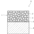
- FIG. 1 is a schematic cross-sectional view of a joined body of a metal material and a ceramic-carbon composite material in the first embodiment.
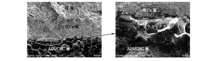
- FIG. 2 is a scanning electron micrograph of the joined surface of the joined body obtained in Example 1 (the magnification on the left side is 500 times and the magnification on the right side is 5000 times).
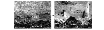
- FIG. 3 is a scanning electron micrograph of the joined surface of the joined body obtained in Example 4 (the magnification on the left side is 500 times and the magnification on the right side is 2000 times).
- FIG. 4 is a scanning electron micrograph of the joined surface of the joined body obtained in Example 5 (left side is 100 times magnification, right side is 2000 times magnification).
- FIG. 1 is a schematic cross-sectional view of a joined body of a metal material and a ceramic-carbon composite material in the first embodiment.
- FIG. 2 is a scanning electron micrograph of the joined surface of the joined body obtained in Example 1 (the magnification on the left side is 500 times and the magn
- FIG. 5 is a scanning electron micrograph of the joined surface of the joined body obtained in Example 6 (the magnification on the left side is 500 times and the magnification on the right side is 2000 times).
- FIG. 6 is a schematic cross-sectional view of a carbon material joined body according to the second embodiment.
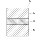
- FIG. 7 is a schematic cross-sectional view of the laminate in the third embodiment.
- FIG. 8 is a schematic cross-sectional view of the laminate in the third embodiment.
- FIG. 9 is a schematic cross-sectional view of a carbon material joined body manufactured in the third embodiment.
- FIG. 1 is a schematic cross-sectional view showing a joined body of a metal material and a ceramic-carbon composite material in the first embodiment.
- a joined body 6 of a metal material and a ceramic-carbon composite material is a joined body of a metal material 4 made of a metal and the ceramic-carbon composite material 1.
- the metal which comprises the metal material 4 is not specifically limited. Specific examples of the metal include W, Mo, Ti, Si, Al, Cr, Cu, Sn, and alloys thereof.
- the metal material 4 is preferably made of at least one of W and Mo. That is, the metal material 4 is preferably made of W, Mo, or an alloy of W and Mo.
- the metal material 4 may have any shape.
- the shape of the metal material 4 may be, for example, a particle shape, a plate shape, a column shape, or a fiber shape.
- the metal material 4 is preferably a powder.
- the ceramic-carbon composite material 1 has a plurality of carbon particles 2 and a ceramic portion 3 made of ceramics.
- the carbon particles 2 for example, natural graphite made of phosphorus-like graphite, flake-like graphite, earth-like graphite or the like, artificial graphite made of coke, mesophase microspheres, or the like, carbonaceous material, or the like is preferably used.
- the particle diameter of the carbon particles 2 is preferably about 50 nm to 500 ⁇ m, more preferably about 1 ⁇ m to 250 ⁇ m, and further preferably about 5 ⁇ m to 100 ⁇ m. If the particle diameter of the carbon particles 2 is too small, the carbon particles 2 tend to aggregate. If the carbon particles 2 are agglomerated too much, the ceramic-carbon composite material 1 may not obtain carbon characteristics. On the other hand, if the particle diameter of the carbon particles 2 is too large, the strength of the fired ceramic-carbon composite material 1 may decrease.
- the plurality of carbon particles 2 may include only one type of carbon particles 2 or may include a plurality of types of carbon particles 2.
- the ceramic part 3 is formed between the plurality of carbon particles 2.
- the ceramic part 3 preferably has a continuous structure. That is, it is preferable that the plurality of carbon particles 2 are integrated by the ceramic part 3 having a continuous structure.
- the ceramic part 3 preferably has a three-dimensional network structure.
- the carbon particles 2 are preferably dispersed in the ceramic portion 3.
- the carbon particles 2 may be dispersed in the ceramic portion 3 as a lump.
- the ceramic part 3 may be comprised by one continuous ceramic part, and may be comprised by the isolated several ceramic part.
- the volume ratio of the carbon particles 2 to the ceramic portion 3 (volume of the carbon particles 2: volume of the ceramic portion 3) in the ceramic-carbon composite material 1 is preferably 95: 5 to 50:50, and 90:10 to More preferably, it is 70:30.
- the ceramic constituting the ceramic part 3 examples include aluminum nitride such as AlN, aluminum oxide such as Al 2 O 3 , silicon carbide such as SiC, silicon nitride such as Si 3 N 4 , boron carbide such as B 4 C, Examples thereof include tantalum carbide such as TaC, niobium carbide such as NbC, zirconium carbide such as ZrC, zinc oxide such as ZnO, silicon oxide such as SiO 2, and zirconium oxide such as ZrO 2 .
- aluminum nitride such as AlN and silicon carbide such as SiC are preferably used for the ceramic portion 3.
- the ceramic composition may be uniform or non-uniform.
- the thickness of the ceramic part 3 is preferably about 100 nm to 10 ⁇ m.
- the ceramic-carbon composite material 1 can be produced, for example, by firing the carbon particles 2 having ceramics attached to the surface.
- the carbon particles 2 having ceramics attached to the surface are produced by, for example, a gas phase method, a liquid phase method, a mechanical mixing method in which ceramics and carbon particles 2 are mixed using a mixer, a slurry method, or a method in which these are combined. can do.
- Specific examples of the vapor phase method include a chemical vapor deposition method (CVD method) and a conversion method (CVR method).
- Specific examples of the liquid phase method include a chemical precipitation method.
- Specific examples of the slurry method include a gel casting method, slip casting, tape casting, and the like.
- the firing temperature, firing time, kind of firing atmosphere, pressure of firing atmosphere, etc. of the carbon particles 2 with ceramics attached to the surface can be appropriately set according to the kind, shape, size, etc. of the material used.
- the firing temperature can be, for example, about 1700 ° C. to 2100 ° C.
- the firing time can be, for example, about 5 minutes to 2 hours.
- the kind of baking atmosphere can be made into inert gas atmosphere, such as nitrogen and argon, for example.
- the pressure of the firing atmosphere can be, for example, about 0.01 MPa to 10 MPa.
- the ceramic-carbon composite material 1 preferably contains a sintering aid.
- the sintering aid include yttrium oxide such as Y 2 O 3 , aluminum oxide such as Al 2 O 3, calcium oxide such as CaO, and silicon oxide such as SiO 2 .
- a bonding layer 5 is formed between the metal material 4 and the ceramic-carbon composite material 1.
- the metal material 4 and the ceramic-carbon composite material 1 are bonded via the bonding layer 5.
- the bonding layer 5 includes a metal carbide and ceramics.
- the metal carbide contained in the bonding layer 5 is formed by carbonizing the metal supplied from the metal material 4 in the bonding step, as will be described in detail later. That is, the metal carbide is derived from the metal material 4. For this reason, it is a carbide of the same kind of metal as the metal constituting the metal material 4. Therefore, the type of metal carbide contained in the bonding layer 5 is determined by the metal constituting the metal material 4. For example, when the metal material 4 is made of at least one of W and Mo, the metal carbide contained in the bonding layer 5 is at least one of tungsten carbide and molybdenum carbide.
- the ceramic contained in the bonding layer 5 is derived from the ceramic portion 3 as described in detail later. For this reason, the ceramic contained in the bonding layer 5 is the same kind of ceramic as the ceramic constituting the ceramic portion 3. For example, when the ceramic portion 3 is made of at least one of aluminum nitride and silicon carbide, the bonding layer 5 also contains at least one of aluminum nitride and silicon carbide. In the bonding layer 5, the metal and the ceramic may exist as a single body, or may exist in a state of being bonded to each other.
- the thickness of the bonding layer 5 is usually about 1 ⁇ m to 200 ⁇ m.
- the bonding layer 5 includes a metal carbide and ceramics. Therefore, the bonding layer 5 has an excellent affinity for the metal material 4 and the ceramic-carbon composite material 1. Therefore, the adhesion strength between the bonding layer 5 and the metal material 4 is high, and the adhesion strength between the bonding layer 5 and the ceramic-carbon composite material 1 is high. As a result, the adhesion strength between the metal material 4 and the ceramic-carbon composite material 1 is also increased. That is, in the bonded body 6, the metal material 4 and the ceramic-carbon composite material 1 are bonded with high bonding strength.
- the joined body 6 does not use a brazing material for joining the metal material 4 and the ceramic-carbon composite material 1. Therefore, the joined body 6 can be used at a temperature higher than the melting point of the brazing material.
- the joined body 6 of the present embodiment can be suitably used as a high-performance X-ray rotating counter cathode, a heat radiating member, a heat-resistant member, a radiation-resistant member, a plasma-damaged member, or the like.
- a laminate obtained by bringing the ceramic-carbon composite material 1 and the metal material 4 into contact with each other is fired.
- the metal contained in the ceramic-carbon composite 1 side surface layer of the metal material 4 is carbonized by the carbon supplied from the carbon particles 2 of the ceramic-carbon composite material 1 to form a metal carbide.
- the bonding layer 5 including the metal carbide and the ceramic of the ceramic portion 3 is formed.
- a joined body 6 in which the metal material 4 and the ceramic-carbon composite material 1 are joined can be obtained.
- the metal material 4 when the metal material 4 is powder, the metal material 4 that is powder is placed on the ceramic-carbon composite material 1 and fired in this state to manufacture the joined body 6. Can do.
- the metal material 4 when the metal material 4 is plate-shaped, the joined body 6 can be manufactured by firing in a state where the ceramic-carbon composite material 1 and the metal material 4 are laminated.
- W and Mo are metals that easily form carbides. For this reason, it becomes easy to form a metal carbide by using the metal material 4 made of at least one of W and Mo. Accordingly, the metal material 4 and the ceramic-carbon composite material 1 can be easily joined.
- the firing temperature and firing time of the ceramic-carbon composite material 1 and the metal material 4, the kind of firing atmosphere, the pressure of the firing atmosphere, and the like can be appropriately set according to the kind, shape, size, etc. of the material used. .
- the firing temperature can be, for example, about 600 ° C. to 1800 ° C.
- the firing time can be, for example, about 2 minutes to 2 hours.
- the kind of baking atmosphere can be made into inert gas atmosphere, such as nitrogen and argon, for example.
- the pressure of the firing atmosphere can be, for example, about 0 MPa to 10 MPa.
- the metal material 4 and the ceramic-carbon composite material 1 can be joined without using a brazing material or an adhesive.
- Example 1 A ceramic-carbon composite material having substantially the same configuration as that of the ceramic-carbon composite material 1 was produced as follows.
- carbon particles 2 graphite (mesophase globules, manufactured by Toyo Tanso Co., Ltd.) was used.
- Aluminum nitride powder (H type manufactured by Tokuyama Corporation) was used as the ceramic.
- a binder solution (2.49 g) in which 1 g) was dissolved in isopropanol (45 g) was mixed by a gel casting method, and the mixture was cast into a plastic mold.
- the volume ratio of graphite to ceramics in the mixture was 80:20.
- the obtained mixture was dried at 80 ° C. for 12 hours under normal pressure to obtain a dried product. Next, the dried product was heated in vacuum at 700 ° C. for 1 hour to remove acrylamide as a binder.
- pulsed current sintering was performed under a vacuum condition at 1900 ° C. for 5 minutes while applying a pressure of 30 MPa by a discharge plasma sintering method.
- an aluminum nitride-graphite composite material was obtained as the ceramic-carbon composite material.
- the bulk density, bending strength and thermal conductivity of the obtained aluminum nitride-graphite composite material were measured as follows. The results are shown in Table 1 below.
- the bending strength was measured by a three-point bending strength test. Specifically, it was measured based on JIS A1509-4.
- Thermal conductivity was measured by a laser flash method. Specifically, it was measured based on JIS A1650-3.
- Example 2 A silicon carbide-graphite composite material was obtained in the same manner as in Experimental Example 1 except that silicon carbide (E10 type manufactured by Ube Industries, Ltd.) was used instead of aluminum nitride.
- the volume ratio of graphite to ceramics was 70:30.
- Example 3 An aluminum nitride-graphite composite material was obtained in the same manner as above except that no sintering aid was used.
- the bulk density and bending strength of the obtained aluminum nitride-graphite composite material were measured as described in Experimental Example 1. The results are shown in Table 1 below. The thermal conductivity is not measured.
- Example 1 After polishing the end face of the aluminum nitride-graphite composite material (cylinder with a thickness of 5 mm and a diameter of 25 mm) prepared in Experimental Example 1 with sandpaper, the tungsten powder as the metal material 4 (particle diameter of about 0.6 ⁇ m, 4.5 g) was placed on the end face of the aluminum nitride-graphite composite so as to have a thickness of 0.3 mm to obtain a laminate. Next, pulse current sintering was performed under vacuum conditions at 1700 ° C. for 5 minutes while applying a pressure of 30 MPa to the laminate. As a result, a joined body 6 of tungsten and an aluminum nitride-graphite composite material was obtained. The bending strength of the test piece obtained by processing and polishing the obtained joined body 6 as follows was measured in the following manner. The results are shown in Table 2 below.
- test piece was processed into a rectangular parallelepiped having a width of about 3 mm, a thickness of 2 to 6 mm, and a length of 20 mm, and was polished with an 80 ⁇ m polishing machine.
- the bending strength was measured by a three-point bending strength test. Specifically, it was measured based on JIS A1509-4.
- Example 2 Aluminum nitride-graphite composite material (5 mm thickness, 25 mm diameter cylinder) was used as the ceramic-carbon composite material, and tungsten powder (particle diameter of about 0.6 ⁇ m, 5 g) was used as the metal material 4 with a thickness of 0. A joined body 6 of tungsten and an aluminum nitride-graphite composite material was obtained in the same manner as in Example 1 except that the thickness was set to 0.5 mm. The obtained bonded body 6 was measured for bending strength after processing and polishing in the same manner as in Example 1. The results are shown in Table 2 below.
- Example 3 In the same manner as in Example 2, a joined body 6 of tungsten and an aluminum nitride-graphite composite material was obtained. The obtained joined body 6 was subjected to a heat cycle treatment. As the method of the thermal cycle treatment, heating-cooling from room temperature to 400 ° C. was repeated 10 times in a vacuum. The obtained bonded body 6 was measured for bending strength after processing and polishing in the same manner as in Example 1. The results are shown in Table 2 below.
- Example 4 Tungsten and ceramic-carbon composite material as in Example 2, except that the silicon carbide-graphite composite material (thickness 5 mm, diameter 25 mm) obtained in Experimental Example 2 was used as the ceramic-carbon composite material. A joined body 6 was obtained. The obtained bonded body 6 was measured for bending strength after processing and polishing in the same manner as in Example 1. The results are shown in Table 2 below.
- the ceramic-carbon composite material 1 was a silicon carbide-graphite composite material (thickness 6 mm, diameter 25 mm) obtained by the same method as in Experimental Example 2, and the metal material 4 was molybdenum (Mo) powder (particles A joined body 6 of molybdenum and a ceramic-graphite composite material was obtained in the same manner as in Example 1, except that the diameter was about 0.7 mm and 3.5 g) was arranged so that the thickness was 0.5 mm.
- the obtained bonded body 6 was measured for bending strength after processing and polishing in the same manner as in Example 1. The results are shown in Table 2 below.
- Example 6 Tungsten and aluminum nitride were performed in the same manner as in Example 1 except that the aluminum nitride-graphite composite material (5 mm thick, 25 mm diameter cylinder) obtained in Experimental Example 3 was used as the ceramic-carbon composite material 1. -A joined body 6 with a graphite composite material was obtained. The obtained bonded body 6 was measured for bending strength after processing and polishing in the same manner as in Example 1. The results are shown in Table 2 below.
- the thickness of the ceramic-graphite composite material in Examples 1 to 6 is the thickness of the test piece after the above processing and polishing.
- FIG. 6 is a schematic cross-sectional view of a carbon material joined body according to the second embodiment.
- the carbon material joined body 6a includes a first member 4a and a second member 5a.
- the carbon material joined body 6a is a joined body of the first member 4a and the second member 5a.
- the first member 4a is made of a carbon material.
- the carbon material is a material mainly composed of carbon.
- the carbon material may contain components other than carbon.
- Specific examples of the carbon material include a carbonaceous material before graphitization, an isotropic graphite material, an anisotropic graphite material such as an extruded material and an embossing material, and a carbon fiber composite material.
- Thermal expansion coefficient of the carbon material is preferably in the range of 0.5 ⁇ 10 -6 /K ⁇ 9.0 ⁇ 10 -6 / K .
- the second member 5a is made of carbon, ceramics or metal.
- Examples of carbon that is preferably used as the constituent material of the second member 5a include the same carbon as the first member 4a.
- Ceramics preferably used as the constituent material of the second member 5a include aluminum nitride, aluminum oxide, silicon carbide, silicon nitride, boron carbide, tantalum carbide, niobium carbide, zirconium carbide, zinc oxide, silicon oxide, and zirconium oxide. Etc.
- the ceramic composition of the second member 5a may be uniform or non-uniform.
- the composition in the vicinity of the interface where the ceramic constituting the second member 5a contacts the ceramic-graphite composite material 1a may be a composition close to the ceramic portion of the ceramic-graphite composite material 1a.
- Examples of the metal preferably used as the constituent material of the second member 5a include Al, Cu, Ag, Ni, Fe, Cr, W, Ti, Mo, Au, and Pt.
- the second member 5a is schematically drawn in a rectangular parallelepiped shape.
- the shape of the second member 5a is not particularly limited.
- the second member 5a may be in a block shape as shown in FIG. 6, or may be in the form of particles, columns, fibers, or the like, for example.
- the particle diameter of the second member 5a can be, for example, about 50 nm to 500 ⁇ m.
- Ceramics-graphite composite 1a A ceramic-graphite composite material 1a is disposed between the first member 4a and the second member 5a. The first member 4a and the second member 5a are joined by the ceramic-graphite composite material 1a.
- the ceramic-graphite composite material 1a includes a plurality of carbon particles 2a and a ceramic portion 3a.
- Examples of the carbon particles 2a include graphite structures such as those obtained by firing organic compounds (synthetic or natural organic compounds), mesocarbon microsphere fired products, resin fired products, petroleum cokes, coal-based cokes, natural graphite, or artificial graphite. Examples thereof include graphite particles. Among these, graphite particles are preferable, and for example, spherulite graphite and spherical natural graphite are more preferably used.
- the particle diameter of the carbon particles is preferably about 50 nm to 500 ⁇ m, more preferably about 1 ⁇ m to 250 ⁇ m, and further preferably about 5 ⁇ m to 100 ⁇ m. If the particle diameter of the carbon particles 2a is too small, the carbon particles 2a tend to aggregate.
- the plurality of carbon particles 2a may include only one type of carbon particle or may include a plurality of types of carbon particles.
- Ceramic part 3a is located between a plurality of carbon particles 2a.
- the ceramic part 3a has a continuous structure. For this reason, the plurality of carbon particles 2a are integrated by the ceramic portion 3a.
- the ceramic portion 3a preferably has a three-dimensional network structure.
- the carbon particles 2a are preferably dispersed in the ceramic portion 3a.
- the carbon particles 2a may be aggregated and dispersed in the ceramic portion 3a.
- the ceramic part 3a may be comprised by one continuous ceramic part, and may be comprised by the isolated several ceramic part.
- Ceramics constituting the ceramic part 3a are not particularly limited. Specific examples of the ceramic constituting the ceramic part include aluminum nitride, aluminum oxide, silicon carbide, silicon nitride, boron carbide, tantalum carbide, niobium carbide, zirconium carbide, zinc oxide, silicon oxide, zirconium oxide and the like.
- the ceramic part 3a may be comprised only from one type of ceramics, and may be comprised from multiple types of ceramics. Moreover, when the ceramic part 3a is comprised from multiple types of ceramics, the composition may be uniform and may be non-uniform
- the carbon material bonded body 6a includes the ceramic-graphite composite material 1a including the plurality of carbon particles 2a and the ceramic portion 3a. Therefore, the ceramic-graphite composite material 1a has high affinity with carbon, ceramics, and metals. Therefore, the adhesion strength between the ceramic-graphite composite material 1a and the first member 4a made of carbon material is high, and the ceramic-graphite composite material 1a and the second member 5a made of carbon, ceramics or metal The adhesion strength between is high. As a result, the adhesion strength between the first member 4a and the second member 5a is also increased. That is, in the carbon material joined body 6a, the first member 4a made of carbon material and the second member 5a made of carbon, ceramics, or metal are joined with high joining strength.
- the interface of the second member 5a on the ceramic-graphite composite material 1a side is preferably close to the composition of the ceramic portion 3a of the ceramic-graphite composite material 1a. Further, the composition in the vicinity of the interface of the second member 5a on the ceramic-graphite composite material 1a side and the composition of the ceramic portion 3a of the ceramic-graphite composite material 1a are compositions that are in solid solution with each other, or are chemically reacted with each other. It is preferable that the composition is easy to cause.
- the coefficient of thermal expansion of the ceramic-graphite composite material 1a is adjusted by adjusting the constituent materials of the carbon particles 2a and the ceramic portion 3a.
- the thermal expansion coefficient of the first member 4a and the thermal expansion coefficient of the second member 5a can be made close to each other. Therefore, the separation between the first member 4a and the ceramic-graphite composite material 1a and the separation between the second member 5a and the ceramic-graphite composite material 1a can be effectively suppressed.
- the ceramic-graphite composite material 1a has the carbon particles 2a and the ceramic portion 3a, the constituent materials of the carbon particles 2a and the ceramic portion 3a are adjusted, and the ratio between the carbon particles 2a and the ceramic portion 3a is adjusted. By doing so, the thermal conductivity of the ceramic-graphite composite material 1a can be adjusted.
- the carbon material joined body 6a of the present embodiment can be preferably used as a heat dissipation substrate, a structural member, and the like because it has the above-described excellent characteristics.
- a laminated body manufacturing process First, a laminated body manufacturing process is performed. In the laminated body manufacturing step, the bonding for carbon material joined body including a plurality of carbon particles 2a (not shown in FIG. 7) having ceramics attached to the surface between the first member 4a and the second member 5a. The material 7a is arrange
- the ceramic adhered to the surface of the carbon particles 2a is for constituting the ceramic portion 3a.
- the kind of ceramic adhering to the surface of the carbon particle 2a can be suitably selected according to the kind of the ceramic part 3a to be formed.
- the composition of the ceramics contained in the bonding material 7a may be uniform or non-uniform.
- the ceramic composition contained in the bonding material 7a and the ceramic composition of the second member 5a may or may not be the same.
- the shape of the ceramic is not particularly limited.
- ceramic particles may be attached to the surfaces of the carbon particles 2a.
- the particle diameter of the ceramic particles is preferably in the range of 1/100 to 1/5 of the particle diameter of the carbon particles.
- substantially the entire surface of the carbon particles can be covered with ceramic particles.
- the particle diameter of the ceramic particles is more preferably in the range of 1/50 to 1/10 of the particle diameter of the carbon particles, and further preferably in the range of 1/40 to 1/20.
- a ceramic layer having a thickness of about 100 nm to 20 ⁇ m may be formed on the surface of the carbon particles 2a.
- the plurality of carbon particles 2a having the ceramic layer formed on the surface may be in the form of particles, or may be integrated by the ceramic layer. That is, a plurality of carbon particles 2a coated with a ceramic layer may be disposed between the first member 4a and the second member 5a, or have substantially the same form as the ceramic-graphite composite material 1a.
- a bonding material 7a may be provided.
- the bonding material 7a is composed of a ceramic-carbon composite having a plurality of carbon particles 2a and a ceramic portion 3a that covers the carbon particles 2a and connects the plurality of carbon particles 2a. You can also.
- Carbon particles with ceramics attached to the surface are prepared by, for example, a gas phase method, a liquid phase method, a mechanical mixing method in which ceramics and carbon particles are mixed using a mixer, a slurry method, or a method in which these are combined.
- a gas phase method includes a chemical vapor deposition method (CVD method) and a chemical vapor reaction method (CVR method).
- a liquid phase method include a coprecipitation method and a sol / gel method.
- Specific examples of the slurry method include a gel casting method and a tape casting method.
- the bonding material 7a having substantially the same form as the ceramic-graphite composite material 1a can be produced by firing the carbon particles produced by the above-described method or the like and having the ceramic adhered to the surface.
- the bonding material 7a is composed of carbon particles with ceramics attached to the surface with a mixture of resin. In this case, the handling of the bonding material 7a becomes easy. Further, the shape of the bonding material 7a can be freely adjusted. For example, the bonding material 7a can be formed into a sheet shape. When the bonding material 7a contains a resin, the bonding material 7a can enter the pores of the carbon particles. By joining the bonding material 7a into the pores of the carbon particles, the bonding strength between the first member 4a and the second member 5a can be increased.
- a thermoplastic resin or a thermosetting resin can be used as the resin.
- the resin is preferably a thermoplastic resin. Specifically, for example, resins such as polyvinyl alcohol and polyvinyl butyral are preferably used.
- the stacked body 8a is fired.
- the first member 4a made of carbon material and the second member 5a made of carbon, ceramics, or metal can be suitably joined by the ceramic-graphite composite material 1a without using a brazing material or the like. it can. It is also possible to join the first and second members 4a and 5a having a shape that cannot be joined by mechanical joining using bolts or the like.
- the first member 4a and the second member 5a can be joined with high joining strength. Further, it is possible to obtain the carbon material joined body 6a in which the first member 4a and the second member 5a are hardly separated. Further, the thermal conductivity between the first member 4a and the second member 5a can be increased.
- the firing temperature and firing time of the laminate, the kind of firing atmosphere, the load pressure, and the like can be appropriately set according to the kind, shape, size, etc. of the material used.
- the firing temperature of the laminate can be, for example, about 1000 ° C. to 2000 ° C.
- the firing time of the laminate can be, for example, about 5 minutes to 1 day.
- the type of the firing atmosphere can be, for example, an inert gas atmosphere such as nitrogen, argon, or helium, or in a vacuum.
- the load pressure can be, for example, about 0 MPa to 40 MPa.
- FIG. 8 is a schematic cross-sectional view of the laminate in the third embodiment.
- a method for joining the first member 4a and the second member 5a in the present embodiment will be described with reference to FIG.
- the second member 5a is particulate.
- the resin layer 10a in which the second member 5a is dispersed in the resin 9a is obtained by disposing a mixture of the particulate second member 5a and the resin 9a on the first member 4a. Form.
- the resin layer 10a can be formed by, for example, a tape casting method.
- the laminate 11a of the first member 4a and the resin layer 10a is fired. Thereby, the carbon-material joined body 12a which the 2nd member 5a baked on the surface of the 1st member 4a shown in FIG. 9 joined is obtained.
- the first member 4a and the second member 5a can be joined with high joining strength.
- baking conditions it can set suitably according to the kind of material to be used, a shape, a magnitude
- Example 7 An isotropic graphite material having a bulk density of 1.8 Mg / m 3 , a bending strength of 40 MPa, and a linear thermal expansion coefficient of 4.7 ⁇ 10 ⁇ 6 / K was prepared. This isotropic graphite material was used as the first member 4a.
- volume ratio volume of spherulite graphite of spherulite graphite having an average particle diameter of 26 ⁇ m and aluminum nitride powder (grade H manufactured by Tokuyama Corporation, average particle diameter of 0.6 ⁇ m, specific surface area of 2.7 m 2 / g). Mixing was performed so that the volume of the aluminum nitride powder was 80:20.
- the obtained slurry was formed into a sheet by a doctor blade method and dried at room temperature to obtain a graphite / aluminum nitride tape having a thickness of 150 ⁇ m.
- This graphite / aluminum nitride tape was used as the bonding material 7a.
- the obtained slurry was formed into a sheet by a doctor blade method and dried at room temperature to obtain an aluminum nitride tape in which aluminum nitride particles having a thickness of 140 ⁇ m were dispersed.
- This aluminum nitride tape was used as the second member 5a.
- the bonding material 7a made of graphite / aluminum nitride tape and the second member 5a made of aluminum nitride tape are arranged in order, and the laminate 8a is arranged. Produced.
- the laminate 8a was held at 1900 ° C. for 5 minutes in a vacuum under a pressure of 30 MPa by a discharge plasma sintering method.
- the first member 4a made of isotropic graphite material and the second member 5a made of aluminum nitride are joined by the ceramic-graphite composite material 1a including the plurality of carbon particles 2a and the ceramic portion 3a.
- a carbon material joined body was obtained.
- Example 7 The observation of the peeled state of the bonded carbon material produced in Example 7 and the three-point bending test were each performed as follows. The results are shown in Table 3 below together with the three-point bending strength and bulk density.
- Example 8 In the same manner as in Example 7, except that an AlN plate having a thickness of 1 mm was used as the second member 5a instead of the aluminum nitride tape, and the sintering temperature by the discharge plasma sintering method was 1700 ° C. A material joined body was prepared.
- Example 8 Next, the observation of the peeled state of the carbon material joined body produced in Example 8 and the three-point bending test were carried out in the same manner as in Example 7. The results are shown in Table 3 below together with the three-point bending strength and bulk density.
- Example 9 A carbon plate having a thickness of 1 mm was used as the second member 5a in place of the aluminum nitride tape, and the carbon temperature was set to 1700 ° C. in the same manner as in Example 7 except that the carbon temperature was 1700 ° C. A material joined body was obtained.
- Example 9 the observation of the peeled state of the carbon material joined body produced in Example 9 and the three-point bending test were carried out in the same manner as in Example 7. The results are shown in Table 3 below together with the three-point bending strength and bulk density.
- Example 10 An isotropic graphite material having a bulk density of 1.8 Mg / m 3 , a bending strength of 40 MPa, and a linear thermal expansion coefficient of 4.7 ⁇ 10 ⁇ 6 / K was prepared. This isotropic graphite material was used as the first member 4a.
- a ceramic layer made of an aluminum nitride tape produced in the same manner as in Example 7 was placed on the first member 4a to produce a laminate 11a.
- the laminate 11a was held at 1900 ° C. for 5 minutes in a vacuum under a pressure of 30 MPa by a discharge plasma sintering method.
- a carbon material joined body was obtained in which the first member 4a made of isotropic graphite material and the particulate second member 5a made of aluminum nitride were directly joined.
- Example 10 observation of the peeled state of the carbon material joined body produced in Example 10 and three-point bending strength were performed in the same manner as in Example 7. The results are shown in Table 3 below together with the three-point bending strength and bulk density.
- Example 7 As in Example 7, an isotropic graphite material having a bulk density of 1.8 Mg / m 3 , a three-point bending strength of 40 MPa, and a linear thermal expansion coefficient of 4.7 ⁇ 10 ⁇ 6 / K is used as the first member. Used as 4a.
- the same aluminum nitride powder (1.5 g) as that used in the production of the aluminum nitride tape in Example 7 was placed, and in this state, the same discharge plasma as in Example 7 was used. Sintering by a sintering method was performed, but no bonding between graphite and aluminum nitride was observed.
- Example 7 As in Example 7, an isotropic graphite material having a bulk density of 1.8 Mg / m 3 , a bending strength of 40 MPa, and a linear thermal expansion coefficient of 4.7 ⁇ 10 ⁇ 6 / K is used as the first member 4a. It was.
- An aluminum nitride plate (thickness 1 mm) was placed on the first member 4a, and in that state, sintering was performed by the same discharge plasma sintering method as in Example 7. Bonding was not observed.
Landscapes
- Chemical & Material Sciences (AREA)
- Engineering & Computer Science (AREA)
- Ceramic Engineering (AREA)
- Materials Engineering (AREA)
- Structural Engineering (AREA)
- Organic Chemistry (AREA)
- Manufacturing & Machinery (AREA)
- Mechanical Engineering (AREA)
- Inorganic Chemistry (AREA)
- Composite Materials (AREA)
- Life Sciences & Earth Sciences (AREA)
- Wood Science & Technology (AREA)
- Ceramic Products (AREA)
- Compositions Of Oxide Ceramics (AREA)
Abstract
Description
また、炭素材からなる部材と、炭素、セラミックスまたは金属からなる部材とのさらなる有力な接合方法が求められている。
図1は、第1の実施形態における金属材とセラミックス-炭素複合材との接合体を示す模式的断面図である。
金属材4を構成する金属は、特に限定されない。金属の具体例としては、例えばW、Mo、Ti,Si、Al、Cr、Cu、Snまたはこれらの合金などが挙げられる。金属材4は、W及びMoの少なくとも一方からなることが好ましい。すなわち、金属材4は、W、MoまたはWとMoとの合金からなることが好ましい。
セラミックス-炭素複合材1は、複数の炭素粒子2と、セラミックスからなるセラミック部3とを有する。
金属材4とセラミックス-炭素複合材1との間には、接合層5が形成されている。この接合層5を介して金属材4とセラミックス-炭素複合材1とが接合されている。接合層5は、金属の炭化物とセラミックスとを含む。
以下、金属材4とセラミックス-炭素複合体材1との接合体6の製造方法の一例について説明する。
以下のようにしてセラミックス-炭素複合材1と実質的に同様の構成を有するセラミックス-炭素複合材を作製した。
アルキメデス法により、かさ密度を測定した。具体的には、JIS A1509-3に基づき測定した。
3点曲げ強度試験により、曲げ強度を測定した。具体的には、JIS A1509-4に基づき測定した。
レーザーフラッシュ法により、熱伝導率を測定した。具体的には、JIS A1650-3に基づき測定した。
窒化アルミニウムの代わりに、炭化ケイ素(宇部興産株式会社製のE10タイプ)を使用したこと以外は、実験例1と同様にして、炭化ケイ素-黒鉛複合材を得た。黒鉛とセラミックスの体積比は70:30とした。
実験例1において、焼結助剤を使用しなかったこと以外は、上記と同様にして、窒化アルミニウム-黒鉛複合材を得た。
黒鉛(メソフェーズ小球体、東洋炭素株式会社製、10g)と、窒化アルミニウム(3.54g)と焼結助剤(Y2O3 0.19g)とを混合した粉末と、エタノール(15g)とをボールミルで混合した。得られた混合物を常圧下、80℃で12時間分間乾燥して乾燥粉末を得た。次に、得られた粉末を、放電プラズマ焼結法にて、30MPaの圧力を印加しつつ、1900℃で5分間、真空条件でパルス通電焼結した。その結果、窒化アルミニウムと黒鉛との複合焼結体が得られた。

実験例1で作製した窒化アルミニウム-黒鉛複合材(厚さ5mm、直径25mmの円柱)の端面を紙やすりで研磨後、金属材4としてのタングステン粉末(粒子径約0.6μm、4.5g)を、窒化アルミニウム-黒鉛複合材の端面上に、厚みが0.3mmとなるように配置し、積層体を得た。次に、積層体に30MPaの圧力を印加しつつ、1700℃で5分間、真空条件下でパルス通電焼結した。その結果、タングステンと窒化アルミニウム-黒鉛複合材との接合体6が得られた。得られた接合体6を以下のように加工、研磨して得られた試験片の曲げ強度を以下の要領で測定した。結果を下記表2に示す。
試験片は、幅約3mm、厚み2~6mm、長さ20mmの直方体に加工し、80μmの研磨盤で研磨した。
3点曲げ強度試験により、曲げ強度を測定した。具体的には、JIS A1509-4に基づき測定した。
セラミックス-炭素複合材として、窒化アルミニウム-黒鉛複合材(厚さ5mm、直径25mmの円柱)を使用したこと、及び金属材4として、タングステン粉末(粒子径約0.6μm、5g)を厚みが0.5mmとなるように配置したこと以外は、実施例1と同様にして、タングステンと窒化アルミニウム-黒鉛複合材との接合体6を得た。得られた接合体6は、実施例1と同様にして、加工と研磨後に曲げ強度を測定した。結果を下記表2に示す。
実施例2と同様にして、タングステンと窒化アルミニウム-黒鉛複合材との接合体6を得た。得られた接合体6に熱サイクル処理を行った。熱サイクル処理の方法は、真空中にて室温から400℃までの加熱-冷却を10回繰り返した。得られた接合体6は、実施例1と同様にして、加工と研磨後に曲げ強度を測定した。結果を下記表2に示す。
セラミックス-炭素複合材として、実験例2で得られた炭化ケイ素-黒鉛複合材(厚さ5mm、直径25mm)を使用したこと以外は、実施例2と同様にして、タングステンとセラミックス-炭素複合材との接合体6を得た。得られた接合体6は、実施例1と同様にして、加工と研磨後に曲げ強度を測定した。結果を下記表2に示す。
セラミックス-炭素複合材1として、実験例2と同様の方法で得られた炭化ケイ素-黒鉛複合材(厚さ6mm、直径25mm)を使用したこと、及び金属材4としてモリブデン(Mo)粉末(粒子径約0.7mm、3.5g)を厚みが0.5mmとなるように配置したこと以外は、実施例1と同様にして、モリブデンとセラミックス-黒鉛複合材との接合体6を得た。得られた接合体6は実施例1と同様にして、加工と研磨後に曲げ強度を測定した。結果を下記表2に示す。
セラミックス-炭素複合材1として、実験例3で得られた窒化アルミニウム-黒鉛複合材(厚さ5mm、直径25mmの円柱)を使用したこと以外は、実施例1と同様にして、タングステンと窒化アルミニウム-黒鉛複合材との接合体6が得られた。得られた接合体6は、実施例1と同様にして、加工と研磨後に曲げ強度を測定した。結果を下記表2に示す。
東洋炭素株式会社製のIG-88黒鉛を紙やすりで研磨後、上部にタングステン粉末(粒子径約0.6μm、5g)を厚みが0.5mmとなるように5g配置した。次に、30MPaの圧力を印加しつつ、1700℃で5分間、真空条件下でパルス通電焼結した。その結果、黒鉛とタングステン粉末とを接合することはできなかった。結果を下記表2に示す。

図6は、第2の実施形態に係る炭素材接合体の略図的断面図である。図6に示すように、炭素材接合体6aは、第1の部材4aと、第2の部材5aとを有する。炭素材接合体6aは、第1の部材4aと第2の部材5aとの接合体である。
第1の部材4aは、炭素材からなる。炭素材は、炭素を主成分とする材料である。炭素材は、炭素以外の成分を含んでいてもよい。炭素材の具体例としては、黒鉛化前の炭素質材、等方性黒鉛材、押出材や型押材等の異方性黒鉛材、炭素繊維複合材などが挙げられる。炭素材の熱膨張係数は、0.5~10-6/K~9.0~10-6/Kの範囲内であることが好ましい。
第2の部材5aは、炭素、セラミックスまたは金属からなる。
第1の部材4aと第2の部材5aとの間には、セラミックス-黒鉛複合材1aが配されている。このセラミックス-黒鉛複合材1aによって、第1の部材4aと第2の部材5aとが接合されている。
まず、積層体作製工程を行う。積層体作製工程では、第1の部材4aと第2の部材5aとの間に、セラミックスが表面に付着した複数の炭素粒子2a(図7においては図示せず)を含む炭素材接合体用接合材7aを配置し、図7に示す積層体8aを作製する。
次に、積層体8aを焼成する。これにより、炭素材からなる第1の部材4aと、炭素、セラミックスまたは金属からなる第2の部材5aとを、ろう材などを用いることなく、セラミックス-黒鉛複合材1aによって好適に接合することができる。また、ボルト等による機械的な接合では接合できないような形状の第1及び第2の部材4a,5aを接合することも可能である。
図8は、第3の実施形態における積層体の略図的断面図である。以下、図8を参照しながら、本実施形態における第1の部材4aと第2の部材5aとの接合方法について説明する。
かさ密度が1.8Mg/m3、曲げ強度が40MPa、線熱膨張係数が4.7×10-6/Kの等方性黒鉛材を用意した。この等方性黒鉛材を第1の部材4aとして用いた。
目視により、調製後の第1の部材4aと第2の部材5aの接合の様子を観察した。
等方性黒鉛の寸法を幅1.6mm×厚さ1.6mm×長さ20mm、支点間距離を15mm、クロスヘッド下降速度を0.5mm/minとした以外はJIS R7222に準拠して測定した。
窒化アルミニウムテープの代わりに、厚さ1mmのAlN板を第2の部材5aとして使用し、放電プラズマ焼結法による焼結温度を1700℃としたこと以外は、実施例7と同様にして、炭素材接合体を作製した。
窒化アルミニウムテープの代わりに、厚さ1mmのSiC板を第2の部材5aとして使用し、放電プラズマ焼結法による焼結温度を1700℃としたこと以外は、実施例7と同様にして、炭素材接合体を得た。
かさ密度が1.8Mg/m3、曲げ強度が40MPa、線熱膨張係数が4.7×10-6/Kの等方性黒鉛材を用意した。この等方性黒鉛材を第1の部材4aとして用いた。
実施例7と同様に、かさ密度が1.8Mg/m3、3点曲げ強さが40MPa、線熱膨張係数が4.7×10-6/Kの等方性黒鉛材を第1の部材4aとして用いた。
実施例7と同様に、かさ密度が1.8Mg/m3、曲げ強度が40MPa、線熱膨張係数が4.7×10-6/Kの等方性黒鉛材を第1の部材4aとして用いた。
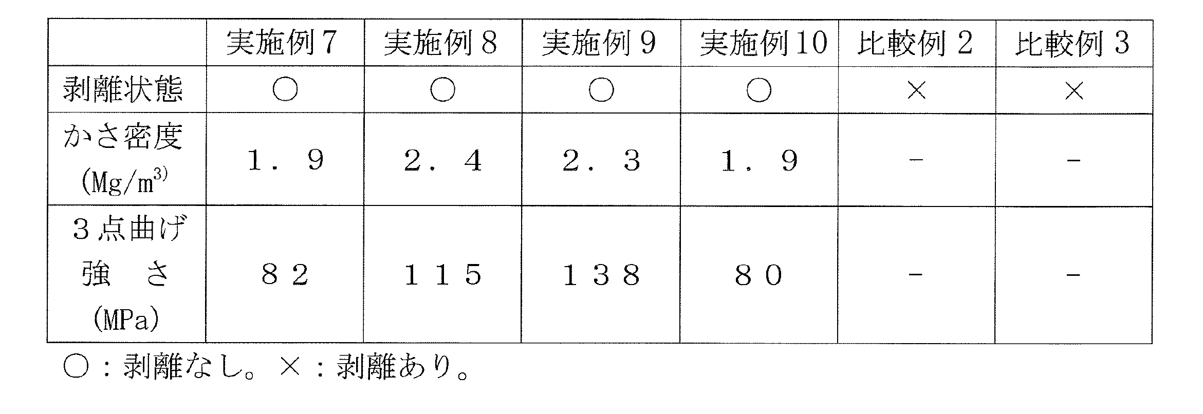
2…炭素粒子
3…セラミック部
4…金属材
5…接合層
6…金属材とセラミックス-炭素複合材との接合体
1a…セラミックス-黒鉛複合材
2a…炭素粒子
3a…セラミック部
4a…第1の部材
5a…第2の部材
6a…炭素材接合体
7a…接合材
8a…積層体
9a…樹脂
10a…樹脂層
11a…積層体
12a…炭素材接合体
Claims (26)
- 金属からなる金属材と、
複数の炭素粒子と、前記複数の炭素粒子間に形成されており、セラミックスからなるセラミック部とを有するセラミックス-炭素複合材とが、接合層を介して接合されている接合体であって、
前記接合層は、前記金属の炭化物と前記セラミックスとを含む、
金属材とセラミックス-炭素複合材との接合体。 - 前記セラミック部は、連続した構造を有する請求項1に記載の金属材とセラミックス-炭素複合材との接合体。
- 前記セラミックスは、窒化アルミニウム及び炭化ケイ素の少なくとも一方からなる請求項1または2に記載の金属材とセラミックス-炭素複合材との接合体。
- 前記金属は、W及びMoの少なくとも一方からなる請求項1~3のいずれか一項に記載の金属材とセラミックス-炭素複合材との接合体。
- 前記セラミックスが炭化ケイ素であり、前記接合層は、前記金属とSiとを含む請求項1~4のいずれか一項に記載の金属材とセラミックス-炭素複合材との接合体。
- 金属材とセラミックス-炭素複合体材との接合体の製造方法であって、
複数の炭素粒子と、前記複数の炭素粒子間に形成されており、セラミックスからなるセラミック部とを有するセラミックス-炭素複合材を用意し、前記セラミックス-炭素複合材と金属材とを接触させた状態で焼成する、金属材とセラミックス-炭素複合材との接合体の製造方法。 - 前記セラミック部は、連続した3次元網目構造を有する請求項6に記載の金属材とセラミックス-炭素複合材との接合体の製造方法。
- 前記セラミックス-炭素複合材は、焼結助剤を含む請求項6または7に記載の金属材とセラミックス-炭素複合材との接合体の製造方法。
- 前記金属材は、粉体である請求項6~8のいずれか一項に記載の金属材とセラミックス-炭素複合材との接合体の製造方法。
- 炭素材からなる第1の部材と、
炭素、セラミックスまたは金属からなる第2の部材と、
前記第1の部材と前記第2の部材とを接合しているセラミックス-黒鉛複合材と、
を備え、
前記セラミックス-黒鉛複合材は、複数の炭素粒子と、前記複数の炭素粒子間に形成されているセラミック部とを含む、
炭素材接合体。 - 前記セラミック部は、連続した構造を有する請求項10に記載の炭素材接合体。
- 前記セラミック部は、窒化アルミニウム、酸化アルミニウム、炭化ケイ素、窒化ケイ素、炭化ホウ素、炭化タンタル、炭化ニオブ、炭化ジルコニウム、酸化亜鉛、酸化ケイ素及び酸化ジルコニウムからなる群から選ばれた少なくとも一種から形成されている請求項10または11に記載の炭素材接合体。
- 炭素材からなる第1の部材と、炭素、セラミックスまたは金属からなり、前記第1の部材に接合された第2の部材とを備える炭素材接合体の製造方法であって、
前記第1の部材と前記第2の部材との間に、セラミックスが表面に付着した炭素粒子を配置して積層体を作製する積層体作製工程と、
前記積層体を焼成する焼成工程と、
を備える炭素材接合体の製造方法。 - 前記積層体作製工程において、前記第1の部材と前記第2の部材との間に、セラミック粒子が表面に付着した炭素粒子を配置する、請求項13に記載の炭素材接合体の製造方法。
- 前記セラミック粒子として、窒化アルミニウム、酸化アルミニウム、炭化ケイ素、窒化ケイ素、炭化ホウ素、炭化タンタル、炭化ニオブ、炭化ジルコニウム、酸化亜鉛、酸化ケイ素及び酸化ジルコニウムからなる群から選ばれた少なくとも一種から形成されているセラミック粒子を用いる請求項14に記載の炭素材接合体の製造方法。
- 前記積層体作製工程において、前記第1の部材と前記第2の部材との間に、前記セラミックスが表面に付着した炭素粒子と樹脂との混合物を配置する請求項13~15のいずれか一項に記載の炭素材接合体の製造方法。
- 前記樹脂として熱可塑性樹脂を用いる請求項16に記載の炭素材接合体の製造方法。
- 前記積層体作製工程において、前記第1の部材と前記第2の部材との間に、複数の炭素粒子と、前記炭素粒子を覆っており、かつ前記複数の炭素粒子を接続しているセラミック部とを有するセラミックス-炭素複合体層を配置する請求項13に記載の炭素材接合体の製造方法。
- 炭素材と、炭素、セラミックスまたは金属からなる部材との接合に用いられる接合材であって、
セラミックスが表面に付着した複数の炭素粒子を含む炭素材接合体用接合材。 - 前記炭素粒子の表面には、セラミック粒子が付着している請求項19に記載の炭素材接合体用接合材。
- 樹脂をさらに含む請求項19または20に記載の炭素材接合体用接合材。
- 前記樹脂は、熱可塑性樹脂である請求項21に記載の炭素材接合体用接合材。
- 前記炭素粒子の表面に付着した前記セラミックスは、前記炭素粒子を覆っており、かつ前記複数の炭素粒子を接続している請求項19に記載の炭素材接合体用接合材。
- シート状である請求項19~23のいずれか一項に記載の炭素材接合体用接合材。
- 炭素材からなる第1の部材と、炭素、セラミックスまたは金属からなり、前記第1の部材に接合された第2の部材とを備える炭素材接合体の製造方法であって、
前記第1の部材の上に、前記第2の部材と樹脂との混合物を配置して作製した積層体を焼成する工程
を備える炭素材接合体の製造方法。 - 前記第2の部材は、粉体である、請求項25に記載の炭素材接合体の製造方法。
Priority Applications (4)
| Application Number | Priority Date | Filing Date | Title |
|---|---|---|---|
| EP12792840.6A EP2716618A4 (en) | 2011-05-27 | 2012-05-22 | A COMPOSITE OF A METAL MATERIAL AND A CERAMIC CARBON COMPOSITE MATERIAL, METHOD OF MANUFACTURING THEREOF, CARBON MATERIAL COMPOUND, JOINT MATERIAL FOR THE CARBON MATERIAL COMPOUND, AND METHOD FOR THE PRODUCTION OF THE CARBON MATERIAL COMPOUND |
| KR1020137031014A KR20140026520A (ko) | 2011-05-27 | 2012-05-22 | 금속재와 세라믹스-탄소 복합재의 접합체, 그 제조 방법, 탄소재 접합체, 탄소재 접합체용 접합재 및 탄소재 접합체의 제조 방법 |
| US14/119,193 US20140086670A1 (en) | 2011-05-27 | 2012-05-22 | Joint of metal material and ceramic-carbon composite material, method for producing same, carbon material joint, jointing material for carbon material joint, and method for producing carbon material joint |
| CN201280025809.9A CN103596905A (zh) | 2011-05-27 | 2012-05-22 | 金属材料与陶瓷-碳复合材料的接合体、其制造方法、碳材料接合体、碳材料接合体用接合材料和碳材料接合体的制造方法 |
Applications Claiming Priority (4)
| Application Number | Priority Date | Filing Date | Title |
|---|---|---|---|
| JP2011118581A JP2012246172A (ja) | 2011-05-27 | 2011-05-27 | 金属材とセラミックス−炭素複合材との接合体及びその製造方法 |
| JP2011118582A JP2012246173A (ja) | 2011-05-27 | 2011-05-27 | 炭素材接合体、炭素材接合体用接合材及び炭素材接合体の製造方法 |
| JP2011-118582 | 2011-05-27 | ||
| JP2011-118581 | 2011-05-27 |
Publications (1)
| Publication Number | Publication Date |
|---|---|
| WO2012165208A1 true WO2012165208A1 (ja) | 2012-12-06 |
Family
ID=47259069
Family Applications (1)
| Application Number | Title | Priority Date | Filing Date |
|---|---|---|---|
| PCT/JP2012/062983 Ceased WO2012165208A1 (ja) | 2011-05-27 | 2012-05-22 | 金属材とセラミックス-炭素複合材との接合体、その製造方法、炭素材接合体、炭素材接合体用接合材及び炭素材接合体の製造方法 |
Country Status (6)
| Country | Link |
|---|---|
| US (1) | US20140086670A1 (ja) |
| EP (1) | EP2716618A4 (ja) |
| KR (1) | KR20140026520A (ja) |
| CN (2) | CN103596905A (ja) |
| TW (1) | TW201302659A (ja) |
| WO (1) | WO2012165208A1 (ja) |
Cited By (3)
| Publication number | Priority date | Publication date | Assignee | Title |
|---|---|---|---|---|
| US20150183691A1 (en) * | 2014-01-02 | 2015-07-02 | Steffen Walter | Manufacturing method and repairing method |
| US11286210B2 (en) * | 2013-02-04 | 2022-03-29 | Toyo Tanso Co., Ltd. | Joined material and method of manufacturing same |
| JP2022533706A (ja) * | 2019-05-20 | 2022-07-25 | バテル エナジー アライアンス,エルエルシー | 緻密なグラファイトを作製するための放電プラズマ焼結方法 |
Families Citing this family (12)
| Publication number | Priority date | Publication date | Assignee | Title |
|---|---|---|---|---|
| US9994489B2 (en) * | 2014-12-30 | 2018-06-12 | The Boeing Company | Bonding dissimilar ceramic components |
| US10293424B2 (en) * | 2015-05-05 | 2019-05-21 | Rolls-Royce Corporation | Braze for ceramic and ceramic matrix composite components |
| CN105130445B (zh) * | 2015-09-15 | 2017-04-26 | 哈尔滨工业大学 | 碳化硅基复合陶瓷生坯连接后共烧结的方法 |
| JP6722089B2 (ja) * | 2016-10-17 | 2020-07-15 | 富士先端技術株式会社 | アルミニウム−黒鉛−炭化物複合体を製造する方法 |
| JP6799790B2 (ja) * | 2016-12-06 | 2020-12-16 | パナソニックIpマネジメント株式会社 | 接合材とそれにより得られる接合体と接合体の製造方法 |
| JP6754973B2 (ja) * | 2017-02-02 | 2020-09-16 | パナソニックIpマネジメント株式会社 | グラファイト放熱板 |
| US11028020B2 (en) * | 2018-09-26 | 2021-06-08 | The Boeing Company | Ceramic composition and method of making the composition |
| CN111286224B (zh) * | 2018-12-07 | 2021-12-07 | 中国计量大学 | 一种用于锅炉受热面抗高温氯腐蚀涂层及制备方法 |
| US20220410529A1 (en) * | 2019-11-22 | 2022-12-29 | Mitsubishi Materials Corporation | Ceramic/copper/graphene assembly and method for manufacturing same, and ceramic/copper/graphene joining structure |
| CN111490027B (zh) * | 2020-03-19 | 2022-04-05 | 深圳第三代半导体研究院 | 一种骨架支撑金属膜及制备方法、烧结方法 |
| KR102845759B1 (ko) * | 2024-01-24 | 2025-08-13 | 한국재료연구원 | 열방호 소재용 금속 탄화물 계면층 제조방법 및 이를 이용한 열방호 소재 |
| CN119035053B (zh) * | 2024-10-31 | 2025-02-21 | 广州众山功能材料有限公司 | 一种陶瓷铝基碳化硅层状复合材料及其制备方法 |
Citations (9)
| Publication number | Priority date | Publication date | Assignee | Title |
|---|---|---|---|---|
| JPS6027660A (ja) * | 1983-07-22 | 1985-02-12 | 株式会社日立製作所 | 炭化ケイ素−黒鉛系接合焼結体の製法 |
| JPH0214879A (ja) * | 1988-06-30 | 1990-01-18 | Human Ind Corp | カーボンセラミック複合体 |
| JPH02180770A (ja) * | 1989-01-06 | 1990-07-13 | Toshiba Corp | 黒鉛とモリブデンの接合方法 |
| JPH05186285A (ja) * | 1992-01-07 | 1993-07-27 | Tokai Carbon Co Ltd | 熱処理用基板とその製造方法 |
| JPH06345553A (ja) | 1993-06-01 | 1994-12-20 | Hitachi Chem Co Ltd | 黒鉛材の接着法 |
| JPH10194877A (ja) * | 1997-01-09 | 1998-07-28 | Toyo Tanso Kk | タングステン/カーボン複合材料 |
| JP2000313677A (ja) | 1999-04-23 | 2000-11-14 | Okayama Ceramics Gijutsu Shinko Zaidan | 炭素系材料と金属との接合体 |
| JP2002321987A (ja) | 2001-04-27 | 2002-11-08 | Nisshinbo Ind Inc | 接着黒鉛材及びその製法 |
| WO2011027757A1 (ja) * | 2009-09-04 | 2011-03-10 | 東洋炭素株式会社 | セラミックス炭素複合材及びその製造方法並びにセラミックス被覆セラミックス炭素複合材及びその製造方法 |
Family Cites Families (9)
| Publication number | Priority date | Publication date | Assignee | Title |
|---|---|---|---|---|
| NL6807820A (ja) * | 1967-07-25 | 1969-01-28 | ||
| JPS60127270A (ja) * | 1983-12-09 | 1985-07-06 | 株式会社日立製作所 | セラミックス複合部材の製造法 |
| EP1394136A1 (en) * | 2001-04-12 | 2004-03-03 | Ibiden Co., Ltd. | Ceramic bonded body and its producing method, and ceramic structure for semiconductor wafer |
| US7858187B2 (en) * | 2006-03-29 | 2010-12-28 | Honeywell International Inc. | Bonding of carbon-carbon composites using titanium carbide |
| AU2008310427B2 (en) * | 2007-10-09 | 2011-03-31 | Krosakiharima Corporation | Nozzle for continuous casting and method for manufacturing the same |
| EP2192096A3 (de) * | 2008-11-26 | 2011-03-23 | Fraunhofer-Gesellschaft zur Förderung der angewandten Forschung e.V. | Verfahren zur Herstellung eines Keramikbauteils |
| CN101462890A (zh) * | 2009-01-12 | 2009-06-24 | 北京科技大学 | 一种Cf/SiC复合材料与钛合金的连接方法 |
| JP5498191B2 (ja) * | 2009-02-16 | 2014-05-21 | 株式会社東芝 | 水素電力貯蔵システムおよび水素電力貯蔵方法 |
| CN101798222A (zh) * | 2010-03-02 | 2010-08-11 | 中国地质大学(北京) | 一种Al2O3-Ni-C-B4C复相陶瓷及其制备方法 |
-
2012
- 2012-05-22 US US14/119,193 patent/US20140086670A1/en not_active Abandoned
- 2012-05-22 WO PCT/JP2012/062983 patent/WO2012165208A1/ja not_active Ceased
- 2012-05-22 CN CN201280025809.9A patent/CN103596905A/zh active Pending
- 2012-05-22 KR KR1020137031014A patent/KR20140026520A/ko not_active Withdrawn
- 2012-05-22 CN CN201510097339.2A patent/CN104744063A/zh active Pending
- 2012-05-22 EP EP12792840.6A patent/EP2716618A4/en not_active Withdrawn
- 2012-05-25 TW TW101118677A patent/TW201302659A/zh unknown
Patent Citations (9)
| Publication number | Priority date | Publication date | Assignee | Title |
|---|---|---|---|---|
| JPS6027660A (ja) * | 1983-07-22 | 1985-02-12 | 株式会社日立製作所 | 炭化ケイ素−黒鉛系接合焼結体の製法 |
| JPH0214879A (ja) * | 1988-06-30 | 1990-01-18 | Human Ind Corp | カーボンセラミック複合体 |
| JPH02180770A (ja) * | 1989-01-06 | 1990-07-13 | Toshiba Corp | 黒鉛とモリブデンの接合方法 |
| JPH05186285A (ja) * | 1992-01-07 | 1993-07-27 | Tokai Carbon Co Ltd | 熱処理用基板とその製造方法 |
| JPH06345553A (ja) | 1993-06-01 | 1994-12-20 | Hitachi Chem Co Ltd | 黒鉛材の接着法 |
| JPH10194877A (ja) * | 1997-01-09 | 1998-07-28 | Toyo Tanso Kk | タングステン/カーボン複合材料 |
| JP2000313677A (ja) | 1999-04-23 | 2000-11-14 | Okayama Ceramics Gijutsu Shinko Zaidan | 炭素系材料と金属との接合体 |
| JP2002321987A (ja) | 2001-04-27 | 2002-11-08 | Nisshinbo Ind Inc | 接着黒鉛材及びその製法 |
| WO2011027757A1 (ja) * | 2009-09-04 | 2011-03-10 | 東洋炭素株式会社 | セラミックス炭素複合材及びその製造方法並びにセラミックス被覆セラミックス炭素複合材及びその製造方法 |
Non-Patent Citations (1)
| Title |
|---|
| See also references of EP2716618A4 |
Cited By (5)
| Publication number | Priority date | Publication date | Assignee | Title |
|---|---|---|---|---|
| US11286210B2 (en) * | 2013-02-04 | 2022-03-29 | Toyo Tanso Co., Ltd. | Joined material and method of manufacturing same |
| US20150183691A1 (en) * | 2014-01-02 | 2015-07-02 | Steffen Walter | Manufacturing method and repairing method |
| JP2022533706A (ja) * | 2019-05-20 | 2022-07-25 | バテル エナジー アライアンス,エルエルシー | 緻密なグラファイトを作製するための放電プラズマ焼結方法 |
| JP7455864B2 (ja) | 2019-05-20 | 2024-03-26 | バテル エナジー アライアンス,エルエルシー | 緻密なグラファイトを作製するための放電プラズマ焼結方法 |
| US12448292B2 (en) | 2019-05-20 | 2025-10-21 | Battelle Energy Alliance, Llc | Spark plasma sintering methods for fabricating dense graphite |
Also Published As
| Publication number | Publication date |
|---|---|
| KR20140026520A (ko) | 2014-03-05 |
| CN103596905A (zh) | 2014-02-19 |
| CN104744063A (zh) | 2015-07-01 |
| TW201302659A (zh) | 2013-01-16 |
| US20140086670A1 (en) | 2014-03-27 |
| EP2716618A4 (en) | 2015-05-27 |
| EP2716618A1 (en) | 2014-04-09 |
Similar Documents
| Publication | Publication Date | Title |
|---|---|---|
| WO2012165208A1 (ja) | 金属材とセラミックス-炭素複合材との接合体、その製造方法、炭素材接合体、炭素材接合体用接合材及び炭素材接合体の製造方法 | |
| JP5322382B2 (ja) | セラミックス複合部材とその製造方法 | |
| CN102482164B (zh) | 陶瓷碳复合材及其制造方法与陶瓷包覆陶瓷碳复合材及其制造方法 | |
| TWI599554B (zh) | Cooling plate, method of manufacturing the same, and device for semiconductor manufacturing apparatus | |
| JP5737547B2 (ja) | 炭化ケイ素被覆黒鉛粒子の製造方法及び炭化ケイ素被覆黒鉛粒子 | |
| JP5773331B2 (ja) | セラミックス接合体の製造方法 | |
| WO2004007401A1 (ja) | 炭化ケイ素基複合材料とその製造方法、および炭化ケイ素基複合材料部品の製造方法 | |
| US20150218676A1 (en) | Metal-carbon composite material, method for producing metal-carbon composite material and sliding member | |
| JPWO2017065139A1 (ja) | アルミニウム−ダイヤモンド系複合体及びその製造方法 | |
| JP2002293636A (ja) | SiC繊維強化型SiC複合材料のホットプレス製造方法 | |
| JP2012246172A (ja) | 金属材とセラミックス−炭素複合材との接合体及びその製造方法 | |
| CN104203870A (zh) | 碳材料—陶瓷材料接合体的制造方法和碳材料—陶瓷材料接合体 | |
| JP7394500B1 (ja) | 金属及び/又はセラミックス・グラファイト含有アルミニウム複合体材料及び金属及び/又はセラミックス・グラファイト含有アルミニウム複合体材料の製造方法 | |
| JP2018108918A (ja) | カーボンナノチューブ及びグラフェンを用いたセラミックマトリックス複合材の製作 | |
| JP4537669B2 (ja) | 炭化ケイ素基接合部品とその製造方法 | |
| JP2012246173A (ja) | 炭素材接合体、炭素材接合体用接合材及び炭素材接合体の製造方法 | |
| JP4439970B2 (ja) | 複合多孔体の製造方法 | |
| JP6236314B2 (ja) | 炭化珪素接合体及びその製造方法 | |
| CN104891996A (zh) | 高取向石墨复合材料制备工艺 | |
| JP5809884B2 (ja) | 炭化ホウ素含有セラミックス接合体及び該接合体の製造方法 | |
| JP7116234B1 (ja) | 複合セラミックスの製造方法 | |
| JP3520320B2 (ja) | セラミックスの接合体の製造法 | |
| JP2000128647A (ja) | 六方晶窒化ほう素焼結体の製造方法 | |
| JP2013060350A (ja) | 炭化ホウ素含有セラミックス−酸化物セラミックス接合体及び該接合体の製造方法 | |
| JP2007153645A (ja) | フレーク状粉末を用いて成形したナノテク用の積層体とその製造方法 |
Legal Events
| Date | Code | Title | Description |
|---|---|---|---|
| 121 | Ep: the epo has been informed by wipo that ep was designated in this application |
Ref document number: 12792840 Country of ref document: EP Kind code of ref document: A1 |
|
| WWE | Wipo information: entry into national phase |
Ref document number: 2012792840 Country of ref document: EP |
|
| WWE | Wipo information: entry into national phase |
Ref document number: 14119193 Country of ref document: US |
|
| ENP | Entry into the national phase |
Ref document number: 20137031014 Country of ref document: KR Kind code of ref document: A |
|
| NENP | Non-entry into the national phase |
Ref country code: DE |