WO2012176705A1 - Machine électrique tournante, et matériau d'isolation et chemisages d'encoche pour machine électrique tournante - Google Patents
Machine électrique tournante, et matériau d'isolation et chemisages d'encoche pour machine électrique tournante Download PDFInfo
- Publication number
- WO2012176705A1 WO2012176705A1 PCT/JP2012/065344 JP2012065344W WO2012176705A1 WO 2012176705 A1 WO2012176705 A1 WO 2012176705A1 JP 2012065344 W JP2012065344 W JP 2012065344W WO 2012176705 A1 WO2012176705 A1 WO 2012176705A1
- Authority
- WO
- WIPO (PCT)
- Prior art keywords
- slot
- rotating electrical
- electrical machine
- stator
- slot liner
- Prior art date
- Legal status (The legal status is an assumption and is not a legal conclusion. Google has not performed a legal analysis and makes no representation as to the accuracy of the status listed.)
- Ceased
Links
Images






Classifications
-
- H—ELECTRICITY
- H02—GENERATION; CONVERSION OR DISTRIBUTION OF ELECTRIC POWER
- H02K—DYNAMO-ELECTRIC MACHINES
- H02K3/00—Details of windings
- H02K3/32—Windings characterised by the shape, form or construction of the insulation
- H02K3/34—Windings characterised by the shape, form or construction of the insulation between conductors or between conductor and core, e.g. slot insulation
- H02K3/345—Windings characterised by the shape, form or construction of the insulation between conductors or between conductor and core, e.g. slot insulation between conductor and core, e.g. slot insulation
-
- H—ELECTRICITY
- H02—GENERATION; CONVERSION OR DISTRIBUTION OF ELECTRIC POWER
- H02K—DYNAMO-ELECTRIC MACHINES
- H02K3/00—Details of windings
- H02K3/32—Windings characterised by the shape, form or construction of the insulation
- H02K3/34—Windings characterised by the shape, form or construction of the insulation between conductors or between conductor and core, e.g. slot insulation
Definitions
- the present invention relates to a rotating electrical machine, an insulating material for a rotating electrical machine, and a slot liner used for the rotating electrical machine.
- Electric rotating machines such as motors closely related to industry and life are basic devices that support modern society.
- an enameled wire is used for the coil.
- an insulating material called a slot liner is disposed in the slot so as to cover the enameled wire, and the enameled wire, the slot liner, and the stator core are fixed with varnish. Necessary insulation performance is secured (for example, refer to patent documents 1 and 2).
- a rotating electrical machine includes a stator core having a plurality of slots arranged in the circumferential direction, a plurality of stator winding conductors inserted in each of the plurality of slots, and a stator winding.
- a stator having a slot liner made of a sheet-like insulating material surrounding a wire conductor, and a rotor rotatably disposed coaxially with the stator, wherein a plurality of slots are filled with an electrically insulating resin;
- asperities are formed on both the front and back sides of the slot liner.
- the slot liner is provided from one end of the slot extending from one end in the axial direction of the stator core to the other end in the axial direction to the other end. It is preferable that the recessed part which comprises these is connected from the one end of a slot to the other end.
- the recess and the protrusion forming the asperities each extend in the axial direction of the stator core.
- the concave and convex portions constituting the concave and convex portions extend obliquely with respect to the axial direction of the stator core, respectively.
- the unevenness is preferably a corrugated unevenness shape or an uneven shape formed by forming an emboss.
- the insulating material for a rotating electrical machine is a sheet-like insulating material for a rotating electrical machine used for electrically insulating the stator winding of the rotating electrical machine, wherein the insulating material is a polymer film and a fiber It is an insulation sheet which consists of at least one of a woven paper, and unevenness is formed in front and back both sides of this insulation sheet.
- the unevenness is preferably a corrugated unevenness shape or an uneven shape formed by forming an emboss.
- the slot liner is disposed in the slot formed in the stator of the rotary electric machine, and the slot formed by bending the insulating material for the rotary electric machine of the sixth or seventh aspect into a tubular shape
- concave and convex concave and convex portions extend in the axial direction of the tubular slot liner.
- the insulation reliability of the rotating electrical machine can be improved.
- FIG. 1 is a view showing a rotating electrical machine according to an embodiment of the present invention, and is a half sectional view including a rotating shaft of the rotating electrical machine.
- FIG. 2 is a cross-sectional view taken along line IV-IV 'of FIG.
- FIG. 3 is an enlarged view of a portion of the slot 31 of FIG.
- FIG. 4 is a view for explaining the surface shape of the slot liner 1a.
- FIG. 5 is a perspective view showing a part of the stator coil 41a covered by the slot liner 1a.
- FIG. 6 is a view for explaining an example of measurement of adhesion of varnish.
- FIG. 7 is a view for explaining the relationship between the size of the unevenness and the contact area.
- FIG. 1 is a view showing a rotating electrical machine according to an embodiment of the present invention, and is a half sectional view including a rotating shaft of the rotating electrical machine.
- FIG. 2 is a cross-sectional view taken along line IV-IV 'of FIG.
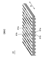
- FIG. 8 is a view showing a first example of the insulating paper 61 used for the slot liner 1.
- FIG. 9 is a view showing a second example of the insulating paper 61 used for the slot liner 1.
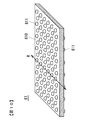
- FIG. 10 is a view showing a third example of the insulating paper 61 used for the slot liner 1.
- FIG. 11 is a view for explaining the case where the extending direction R of the unevenness of the slot liner 1 substantially coincides with the extending direction R1 of the slot 31.
- FIG. 12 is a view for explaining the case where the extending direction R of the unevenness of the slot liner 1 is oblique to the extending direction R1 of the slot 31.
- FIG. 13 is a view for explaining varnish filling in the case of using the slot liner 100 without unevenness.
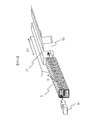
- FIG. 14 is a perspective view showing the insulating paper 61 when the uneven surface is configured as a flat surface.
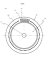
- FIGS. 1 and 2 are views for explaining an embodiment of a rotating electrical machine according to the present invention, showing an entire configuration of the rotating electrical machine.
- FIG. 1 is a half sectional view including a rotating shaft 11 of a rotating electrical machine 10.
- FIG. 2 is a cross-sectional view taken along line IV-IV 'of FIG.
- a permanent magnet rotating electric machine will be described as an example of the rotating electric machine.
- the rotor 20 and the stator 30 are arrange
- permanent magnets are embedded in the rotor 20.
- a plurality of slots 31 are formed in the stator core 32 of the stator 30 along the circumferential direction, and a stator coil 41 is incorporated in each of the slots 31.
- the stator coil 41 is supplied with power via a connection terminal (not shown), thereby generating a magnetic field.
- each of the slots 31 and the stator coils 41 are normally arranged at equal intervals in the circumferential direction of the stator 30, only a part is shown here. In the example shown in FIG. 2, four stator coils 41 having a rectangular cross-sectional shape are incorporated in the slots 31, but the shape and number of coils are not limited to these.
- the interaction between the magnetic field produced by the current flowing in the stator coil 41 and the magnetic field of the permanent magnet embedded in the rotor 20 generates a rotational force in the rotor 20.
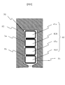
- FIG. 3 is an enlarged view of a portion of the slot 31 of FIG.
- stator coils 41 (41a, 41b, 41c, 41d) disposed in the slots 31 are surrounded by slot liners 1a, 1b formed of sheet-like insulating material (hereinafter referred to as insulating paper) It is done.
- insulating paper sheet-like insulating material
- a mode is shown in which two coils are surrounded by one slot liner, and the slot liner 1a is provided for the stator coils 41a and 41b on the outer peripheral side, and the stator coil 41c on the inner peripheral side, A slot liner 1b is provided for 41d.
- the slot liner 1a is bent so as to surround four sides of each of the stator coils 41a and 41b.
- the slot liner 1b is bent so as to surround four sides of each of the stator coils 41c and 41d.
- an enamel film is generally applied to the surface of a rectangular cross-section conductor, which is generally called a rectangular enameled wire.
- insulating paper preferable as the slot liners 1a and 1b is called composite insulating paper in which a heat-resistant fibrous non-woven paper is laminated on both sides of a polymer film. Slot liners 1a and 1b are formed by bending and forming the composite insulating paper.
- the insulating varnish 51 is filled.
- the varnish 51 is an electrically insulating resin, and an epoxy resin, a heat-resistant alkyd resin, an unsaturated polyester resin, or the like is used. By curing the varnish 51, the stator coils 41a to 41d and the slot liners 1a and 1b are fixed to the stator core 32.
- the varnish 51 it is preferable to use a thermosetting resin which is liquid when filled in the slot 31, and which is heated and cured after filling.
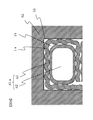
- FIG. 4 is a partially enlarged view of FIG. 3 so that the surface shape of the slot liner 1a can be easily understood.
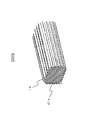
- FIG. 5 is a perspective view showing a part of the stator coil 41a covered by the slot liner 1a. Although FIGS. 4 and 5 show the slot liner 1a around the stator coil 41a, the same configuration applies to the slot liners around the stator coils 41b to 41d.
- both front and back sides of the slot liners 1a and 1b are described in a planar shape, but the detailed surface shape has an uneven shape as shown in FIG.
- the stator coil 41a is composed of a conductor 42 and an enamel coating 43 covering it.
- the concave and convex portions formed on the front and back sides of the slot liner 1a are, as shown in FIG. 5, the extending direction of the stator coil 41a, that is, the extending direction of the slots 31 extending in the axial direction of the stator core 32. It extends in line with the
- Varnish 51 is filled in the gap between the slot liner 1a and the slot inner wall, the gap between the slot liner 1a and the stator coil 41, and the gap between the adjacent slot liners.
- the present embodiment is characterized in that both the front and back surfaces of the slot liners 1a and 1b are uneven, whereby the slot liners 1a and 1b and the varnish 51 are compared to the case where the surface of the slot liner is flat.
- the contact area with can be made larger.
- the inventor In the process of evaluating the characteristics of the insulating structure in which the enameled wire and the insulating paper forming the slot liner are fixed by the varnish, the inventor has fixed the varnish 51 and the slot liners 1a and 1b with respect to the peeling of the bonding portion as described above. And the interface adhesion was found to be inferior to the interface adhesion between the fixed varnish 51 and the enameled wire (the stator coil 41).
- FIG. 6 shows an example of adhesion measurement of varnish.
- the sample of the form shown to Fig.6 (a) and the sample of the form shown to FIG. 6 (b) were compared.
- two enameled wires (flat wire) 60a and 60b are adhered with a varnish.
- the enameled wires 60a and 60b were peeled off as shown by the arrows, and the tensile breaking force (N) at that time was measured.
- N tensile breaking force
- the insulating paper 61 is sandwiched between the enameled wires 60a and 60b, and each is adhered with a varnish, and the tensile breaking strength (N) is obtained as in the case of FIG. It was measured.
- the measurement was performed for each of the case where the unevenness was formed on the front and back sides of the insulating paper 61 and the case where the unevenness was not formed.
- the surface film of the enameled wire 60a, 60b is polyamide imide
- the varnish is epoxy resin
- the insulating paper 61 is aramid fiber non-woven paper.
- FIG. 6 (c) shows the measurement results as a graph
- the measurement data on the left side is the case of the form of FIG. 6 (a).
- the measurement data in the center shows the case of using the insulating paper 61 in which the unevenness is not formed in the form of FIG. 6 (b), and the measurement data on the right side is the insulation in which the unevenness is formed in the form of FIG.
- the case where paper 61 is used is shown.
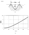
- FIG. 7 is a view for explaining the relationship between the size of the asperity and the contact area, and here, as an example, the case where a sine-like asperity surface is formed will be considered.
- FIG. 7A shows the surface shape in the case where the slot liner 1 is cut so as to be orthogonal to the extending direction of the recess and the protrusion.
- the surface shape is sinusoidal.
- the depth of the unevenness is b
- the distance between the convex portions is a.
- b / a 0 corresponds to no unevenness, and the area ratio at that time is 1. As the ratio b / a increases, the area ratio also increases.
- the spacing and depth of the asperities may be determined based on the relationship shown in FIG. 7 (b) in accordance with the required adhesive strength.
- the front and back surfaces are both sinusoidal undulated surfaces, and the phase of the sine wave is shifted 180 degrees between the front and back sides. Therefore, the positions of the convex portions on the front and back, and the positions of the concave portions are the same.
- the front and back surfaces are both in the form of sinusoidal undulations, but the phases of the sine waves coincide on the front and back sides.
- the convex portion 61a and the concave portion 61b are formed to extend in one direction indicated by the arrow R.
- both the front and back sides have an uneven shape formed by forming an emboss.
- a plurality of hemispherical convex portions 611 are formed on the front and back sides of the insulating paper 61 so as to protrude from the sheet-like member 610.
- the plurality of convex portions 611 are linearly arranged in the direction indicated by the arrow R.
- the portion of the sheet-like member 610 between the convex portions 611 corresponds to the concave portion 61 b in FIGS.
- a plurality of convex portions 611 are formed in the same arrangement.
- the convex part 611 it is possible to form the convex part 611 so that it may align in a straight line not only in the arrow R direction but other directions.
- the plurality of convex portions 611 are formed to be arranged on the lattice points of the square lattice, the plurality of convex portions 611 are aligned in a straight line in the R direction and aligned in a direction orthogonal to the R direction. be able to.
- the plurality of convex portions 611 may be randomly arranged.
- the shape, size, and arrangement of the convex portions 611 are not limited, it is desirable that the heights be as uniform as possible.
- the insulating paper 61 having a surface shape as shown in FIGS. 8 to 10 is, for example, pressed by pressing the non-woven paper of the aramid fiber described above with a mold in which a large number of wavy surfaces and hemispherical concave surfaces are formed. It can be formed. Alternatively, a sheet-like insulating paper of uniform thickness may be formed into a wave shape. Furthermore, instead of insulating paper made of a uniform material, using insulating paper made by laminating different materials in upper and lower two layers, or using laminated insulating paper made in three layers with upper and lower layers and an intermediate layer made of different materials I don't care. As a material used for the insulating paper, a polymer film such as polyethylene terephthalate and non-woven paper such as aramid fibers are generally used.
- FIGS. 8 to 10 are diagrams for explaining the relationship between the unevenness formed on the surface of the slot liner 1 and the slots 31.
- FIG. The slot liner 1 formed by bending the insulating paper 61 into a predetermined cylindrical shape as shown in FIGS. 8 to 10 is inserted into the slot 31 from the end face side of the stator core 32. Thereafter, a pine-shaped stator coil 41 called a segment coil is mounted in the slot 31 so as to be inserted into the space formed in the slot liner 1.
- the slot liner 1 is configured such that the extending direction R of each unevenness at the time of mounting the slot substantially matches the extending direction R1 of the slot 31 in the stator core 32 (axial direction of the stator core 32). It is done. Therefore, the contact area with the inner wall of the slot and the stator coil 41 is reduced, and the sliding resistance can be reduced when the slot liner 1 is incorporated into the slot 31 and when the stator coil 41 is inserted into the slot liner 1 .
- the extending direction of the asperities is substantially coincident with the slot extending direction R1, and the recess forming the varnish filling space penetrates the slot 31 in the axial direction. Therefore, the varnish can be filled to the inside of the slot 31 in the subsequent varnish filling process, and the generation of the space not filled with the varnish can be prevented.
- the stator core 32 is disposed so that the axial direction is vertical, and varnish is filled in the slot 31 so that varnish is dropped on the core end face portion.
- the recessed portion of the slot liner 1 penetrates the inside of the slot 31 in the axial direction, so that gravity can be used to reliably fill the varnish 51 to the back of the slot 31, thereby preventing the varnish unfilled space from being generated. .
- the inner wall of the slot or the coil surface and the slot liner 100 tend to be in close contact with each other as shown by the reference symbol B.
- the inner wall of the slot or the coil surface and the slot liner 100 are in close contact with each other in a wide area as shown in FIG. 13, even if the capillary phenomenon is used, an area where varnish is not filled is easily generated. Unavoidable.
- the area of the inner wall of the slot and the area where the coil surface and the slot liner 1 are in contact is small, unfilling in the contact portion is unlikely to occur due to the effect of capillary action.
- the top of the convex portion is a curved surface, but may be planar. Also in this case, the area of the inner wall of the slot or the area where the coil surface is in contact with the slot liner 1 is smaller than that of the conventional surface contact area, and it is difficult for the contact area to be unfilled.
- the extending direction R of the asperity is configured to be oblique to the slot extending direction R1 (that is, the slot inserting direction). Even in the case of such an oblique configuration, the strength against bending and buckling is improved as compared with the slot liner without the unevenness, and the above-described effect on the varnish filling can be obtained.
- the concave portion filled with the varnish 51 is oblique to the slot extending direction, the effect of preventing the positional deviation of the stator coil 41 and the slot liner 1 in the axial direction is improved.
- the varnish 51 filled in the space other than the slot liner 1 and the stator coil 41 in the slot 31 becomes a solid resin cured product by heat curing.
- the adhesive force of the cured varnish 51 acts as a locking mechanism for preventing the positional displacement, against the shear force which tends to cause the slot liner 1 and the stator coil 41 to be displaced in the axial direction, that is, to slip out.
- the hardened varnish 51 crosses the slot 31 obliquely, and the effect of the locking mechanism is improved as compared with the case of FIG.
- FIGS. 11 and 12 shows the case where the insulating paper 61 shown in FIG. 9 is used, the same applies to the case where the insulating paper 61 shown in FIGS. 9 and 10 is used. That is, the extending direction R of the convex portion 61a and the concave portion 61b of FIG. 9 or the extending direction R of the convex portion 611 of FIG. 10 may be set as in the case of FIGS.
- the concavo-convex shape is sinusoidal, it may be a non-sinusoidal wave. Further, instead of forming the uneven shape by the curved surface, the uneven shape may be formed by a plane as shown in FIG. If the width W of the convex portion 61a is set small, the area of the close contact surface when in close contact with the inner wall of the slot or the stator coil can be reduced. Furthermore, although the convex portion and the concave portion extend in a straight line, they may be in a curved line instead of a straight line as long as they penetrate the slot 31 in the axial direction.
- the stator coil 41 has been described by taking a rectangular wire of rectangular cross section as an example, but it is provided so as to surround a slot liner provided so as to wrap a thick round wire or a bundle of round wires.
- the slot liner 1 of the present embodiment can also be applied to the slot liner.
- the slot liner 1 of the present embodiment may be applied to a stator coil that is not enameled.
- each of the plurality of slots 31 is surrounded by the stator core 32 in which the plurality of slots 31 are arranged in the circumferential direction and the slot liner 1 made of sheet-like insulating material.
- a stator 30 having a plurality of stator coils 41 inserted therein and a rotor 20 rotatably disposed coaxially with the stator 30, and a plurality of slots 31 are filled with varnish 51.
- unevenness is formed on both the front and back sides of the slot liner 1.
- the area of the bonding surface between the slot liner 1 and the varnish 51 can be increased, and the bonding strength between the slot liner 1 and the varnish 51 can be improved.
- peeling of the adhesive surface due to vibration or the like can be reduced, and the insulation reliability can be improved.
- the slot liner 1 is provided from one end of the stator core 32 to one end to the other end in the axial direction of the stator core 32 from the one end to the other end of the slot 31. It communicates up to. With such a configuration, the varnish 51 can be reliably filled to the depth in the axial direction of the slot 31, and generation of the varnish unfilled space can be prevented.
- the slot 61 can be formed by extending the concave portion 61 b and the convex portion 61 a constituting the concave and convex portions of the slot liner 1 in the axial direction of the stator core 32 or obliquely with respect to the axial direction.
- the strength against buckling deformation when inserting the liner 1 into the slot 31 can be improved.
- the convex portions 611 may be arranged in the axial direction of the stator core 32 (that is, discontinuously extended), or may be arranged obliquely to the axial direction. By doing this, the same effect can be achieved.
- the asperity is formed into a concavo-convex shape of a wave shape or an emboss shape formed by forming an emboss
- the wide area of the slot liner 1 can be prevented from adhering to the inner wall of the slot and the stator coil 41, and the generation of the varnish unfilled area can be prevented.
- the insulating material in the form of a sheet used for electrically insulating the stator winding (the stator coil 41) of the rotating electric machine
- the insulating material is at least at least a polymer film and a fiber non-woven paper It is an insulating sheet which consists of one side, Comprising: An unevenness
- corrugation is formed in front and back both surfaces of this insulating sheet.
- the above description is merely an example, and the present invention is not limited to the above embodiment as long as the features of the present invention are not impaired.
- the inner rotor type rotating electrical machine has been described as an example, but the present invention can be applied to an outer rotor type rotating electrical machine as well.
Landscapes
- Engineering & Computer Science (AREA)
- Power Engineering (AREA)
- Insulation, Fastening Of Motor, Generator Windings (AREA)
- Manufacture Of Motors, Generators (AREA)
Abstract
Priority Applications (3)
| Application Number | Priority Date | Filing Date | Title |
|---|---|---|---|
| CN201280030086.1A CN103609000B (zh) | 2011-06-23 | 2012-06-15 | 旋转电机、旋转电机用绝缘材料及槽衬 |
| DE112012002571.7T DE112012002571T5 (de) | 2011-06-23 | 2012-06-15 | Rotierende Maschine und Isolator und Spaltauskleidung für rotierende Maschine |
| US14/123,588 US20140117805A1 (en) | 2011-06-23 | 2012-06-15 | Rotating Machine and Insulator and Slot Liner for Rotating Machine |
Applications Claiming Priority (2)
| Application Number | Priority Date | Filing Date | Title |
|---|---|---|---|
| JP2011139702A JP5839851B2 (ja) | 2011-06-23 | 2011-06-23 | 回転電機 |
| JP2011-139702 | 2011-06-23 |
Publications (1)
| Publication Number | Publication Date |
|---|---|
| WO2012176705A1 true WO2012176705A1 (fr) | 2012-12-27 |
Family
ID=47422543
Family Applications (1)
| Application Number | Title | Priority Date | Filing Date |
|---|---|---|---|
| PCT/JP2012/065344 Ceased WO2012176705A1 (fr) | 2011-06-23 | 2012-06-15 | Machine électrique tournante, et matériau d'isolation et chemisages d'encoche pour machine électrique tournante |
Country Status (5)
| Country | Link |
|---|---|
| US (1) | US20140117805A1 (fr) |
| JP (1) | JP5839851B2 (fr) |
| CN (1) | CN103609000B (fr) |
| DE (1) | DE112012002571T5 (fr) |
| WO (1) | WO2012176705A1 (fr) |
Cited By (2)
| Publication number | Priority date | Publication date | Assignee | Title |
|---|---|---|---|---|
| TWI790182B (zh) * | 2021-11-25 | 2023-01-11 | 日商日機裝股份有限公司 | 槽襯及旋轉電機 |
| US20230253849A1 (en) * | 2020-08-20 | 2023-08-10 | Atop S.P.A. | Stator, apparatus and method for peparing a pre-shaped insulator |
Families Citing this family (24)
| Publication number | Priority date | Publication date | Assignee | Title |
|---|---|---|---|---|
| US20160099622A1 (en) * | 2014-10-07 | 2016-04-07 | Hamilton Sundstrand Corporation | Hybrid Conductor for Generator Stator Winding |
| JP2016174441A (ja) * | 2015-03-16 | 2016-09-29 | 日東シンコー株式会社 | スロットライナー |
| JP6547499B2 (ja) * | 2015-08-03 | 2019-07-24 | 株式会社デンソー | 回転電機 |
| JP6335944B2 (ja) * | 2015-08-11 | 2018-05-30 | 株式会社三井ハイテック | 積層鉄心の樹脂封止方法 |
| US20170104380A1 (en) * | 2015-10-08 | 2017-04-13 | Uqm Technologies, Inc. | Slot liner thermal conductivity for electric motors |
| JP2017163797A (ja) * | 2016-03-11 | 2017-09-14 | 本田技研工業株式会社 | 電動機用ステータの製造方法および電動機用ステータ |
| CN109923771B (zh) * | 2016-11-18 | 2022-10-04 | 日立安斯泰莫株式会社 | 定子的制造方法 |
| DE102016124799A1 (de) * | 2016-12-19 | 2018-06-21 | ATE Antriebstechnik und Entwicklungs GmbH & Co. KG | Verfahren zur Herstellung eines Stators und zugehöriger Stator |
| JP6938933B2 (ja) * | 2017-02-03 | 2021-09-22 | トヨタ自動車株式会社 | 回転電機のステータ |
| JP6906329B2 (ja) * | 2017-03-01 | 2021-07-21 | 日立Astemo株式会社 | 固定子、回転電機、固定子の製造方法、及び回転電機の製造方法 |
| CN109149803A (zh) * | 2017-06-28 | 2019-01-04 | 天津市松正电动汽车技术股份有限公司 | 一种扁线电机定子槽绝缘结构及其加工设备、加工工艺 |
| DE102017216858A1 (de) * | 2017-09-22 | 2019-03-28 | BMTS Technology GmbH & Co. KG | Elektrische Medienspaltmaschine, Verdichter und/oder Turbine |
| JP7025224B2 (ja) * | 2018-01-18 | 2022-02-24 | 株式会社Soken | 回転電機のステータ |
| US11223253B2 (en) * | 2018-07-12 | 2022-01-11 | Hitachi Astemo, Ltd. | Stator for rotating electrical machine, rotating electrical machine, and method of producing stator for rotating electrical machine |
| WO2020017133A1 (fr) * | 2018-07-18 | 2020-01-23 | 株式会社日立製作所 | Machine électrique rotative de type à entrefer radial et à enroulements répartis et son stator |
| US10855131B2 (en) | 2019-03-22 | 2020-12-01 | Hamilton Sundstrand Corporation | Potting and insulation system for a concentrated coil soil stator |
| DE102019113789A1 (de) * | 2019-05-23 | 2020-11-26 | Dr. Ing. H.C. F. Porsche Aktiengesellschaft | Stator einer elektrischen Maschine |
| DE102019124226A1 (de) * | 2019-09-10 | 2021-03-11 | Schaeffler Technologies AG & Co. KG | Elektrische Maschine mit Schultern zwischen mehreren Leitern und Laschen eines Wicklungsaufnahmebereiches eines Stators oder eines Rotors |
| DE102019216281A1 (de) * | 2019-10-23 | 2021-04-29 | Volkswagen Aktiengesellschaft | Isolationskörper eines Stators mit erhöhter Steifigkeit |
| DE102020109211A1 (de) | 2020-04-02 | 2021-10-07 | Schaeffler Technologies AG & Co. KG | Leistungserzeugende Komponente einer elektrischen Rotationsmaschine und elektrische Rotationsmaschine |
| CN111633127B (zh) * | 2020-06-08 | 2022-04-05 | 哈尔滨电气动力装备有限公司 | 湿绕组电机转子槽衬弯形工具 |
| JP7763673B2 (ja) * | 2022-01-20 | 2025-11-04 | 株式会社日立産機システム | 回転電機および産業機械 |
| US12451745B2 (en) | 2023-06-06 | 2025-10-21 | Ford Global Technologies, Llc | Electric machine slot liner with enhanced varnish control |
| DE102024104928A1 (de) * | 2024-02-22 | 2025-08-28 | Bayerische Motoren Werke Aktiengesellschaft | Elektrische Maschine für ein Kraftfahrzeug, insbesondere für einen Kraftwagen, sowie Verfahren zum Herstellen einer solchen elektrischen Maschine |
Citations (6)
| Publication number | Priority date | Publication date | Assignee | Title |
|---|---|---|---|---|
| JPH0471346A (ja) * | 1990-07-12 | 1992-03-05 | Fuji Electric Co Ltd | 高圧回転機コイル |
| JPH09327144A (ja) * | 1996-06-07 | 1997-12-16 | Hitachi Ltd | 電気絶縁線輪及びその製造方法 |
| JP2000125499A (ja) * | 1998-10-13 | 2000-04-28 | Toshiba Corp | 絶縁コイルの固定部材、該固定部材を備えた回転電機及び絶縁コイルの固定方法 |
| JP2005086852A (ja) * | 2003-09-05 | 2005-03-31 | Yaskawa Electric Corp | 回転機の固定子 |
| JP2005110450A (ja) * | 2003-10-01 | 2005-04-21 | Toshiba Corp | 低抵抗コロナ防止テープまたはシートおよび回転電機の固定子コイル |
| JP2010155877A (ja) * | 2008-12-26 | 2010-07-15 | Nitto Shinko Kk | プリプレグシート |
Family Cites Families (19)
| Publication number | Priority date | Publication date | Assignee | Title |
|---|---|---|---|---|
| US3515923A (en) * | 1969-04-04 | 1970-06-02 | Du Pont | Dynamoelectric machine and corrugated plastic slot liner insert therefor |
| JPS5482601A (en) * | 1977-12-14 | 1979-07-02 | Hitachi Ltd | Winding for electric rotary machine |
| JPS63287344A (ja) * | 1987-05-18 | 1988-11-24 | Shinko Electric Co Ltd | 回転電機のコイル絶縁 |
| US4994700A (en) * | 1990-02-15 | 1991-02-19 | Sundstrand Corporation | Dynamoelectric machine oil-cooled stator winding |
| JPH0471345A (ja) * | 1990-07-11 | 1992-03-05 | Fuji Electric Co Ltd | 回転電機のコイルスロット内隙き間調整板 |
| US5721397A (en) * | 1995-06-07 | 1998-02-24 | Weinberg; Martin J. | Electrical insulation and products protected thereby |
| JP3511948B2 (ja) * | 1998-07-15 | 2004-03-29 | 株式会社デンソー | 車両用交流発電機およびそれに用いられる固定子の製造方法 |
| JP3196738B2 (ja) * | 1998-09-11 | 2001-08-06 | 株式会社デンソー | ステータ製造装置及びステータ製造方法 |
| JP3752431B2 (ja) * | 2001-02-28 | 2006-03-08 | 株式会社日立製作所 | 回転電機及びその製造方法 |
| JP3551375B2 (ja) * | 2001-12-26 | 2004-08-04 | 株式会社デンソー | 回転電機およびその製造方法 |
| JP4001040B2 (ja) * | 2003-03-28 | 2007-10-31 | 株式会社デンソー | 回転電機の固定子 |
| JP3903964B2 (ja) * | 2003-06-18 | 2007-04-11 | 株式会社デンソー | 回転電機の固定子 |
| US7081697B2 (en) * | 2004-06-16 | 2006-07-25 | Visteon Global Technologies, Inc. | Dynamoelectric machine stator core with mini caps |
| JP2007336725A (ja) * | 2006-06-16 | 2007-12-27 | Denso Corp | 回転電機の固定子 |
| JP4475470B2 (ja) * | 2007-04-05 | 2010-06-09 | 三菱電機株式会社 | 回転電機のコイル部の絶縁構造 |
| JP2010051087A (ja) * | 2008-08-21 | 2010-03-04 | Toyota Motor Corp | 固定子構造 |
| JP5438951B2 (ja) * | 2008-11-28 | 2014-03-12 | 日東シンコー株式会社 | プリプレグシート |
| JP2010200596A (ja) * | 2009-01-28 | 2010-09-09 | Aisin Aw Co Ltd | 回転電機用電機子及びその製造方法 |
| CN102013746A (zh) * | 2010-11-24 | 2011-04-13 | 张嘉宏 | 一种绝缘垫槽纸 |
-
2011
- 2011-06-23 JP JP2011139702A patent/JP5839851B2/ja active Active
-
2012
- 2012-06-15 CN CN201280030086.1A patent/CN103609000B/zh active Active
- 2012-06-15 DE DE112012002571.7T patent/DE112012002571T5/de active Pending
- 2012-06-15 WO PCT/JP2012/065344 patent/WO2012176705A1/fr not_active Ceased
- 2012-06-15 US US14/123,588 patent/US20140117805A1/en not_active Abandoned
Patent Citations (6)
| Publication number | Priority date | Publication date | Assignee | Title |
|---|---|---|---|---|
| JPH0471346A (ja) * | 1990-07-12 | 1992-03-05 | Fuji Electric Co Ltd | 高圧回転機コイル |
| JPH09327144A (ja) * | 1996-06-07 | 1997-12-16 | Hitachi Ltd | 電気絶縁線輪及びその製造方法 |
| JP2000125499A (ja) * | 1998-10-13 | 2000-04-28 | Toshiba Corp | 絶縁コイルの固定部材、該固定部材を備えた回転電機及び絶縁コイルの固定方法 |
| JP2005086852A (ja) * | 2003-09-05 | 2005-03-31 | Yaskawa Electric Corp | 回転機の固定子 |
| JP2005110450A (ja) * | 2003-10-01 | 2005-04-21 | Toshiba Corp | 低抵抗コロナ防止テープまたはシートおよび回転電機の固定子コイル |
| JP2010155877A (ja) * | 2008-12-26 | 2010-07-15 | Nitto Shinko Kk | プリプレグシート |
Cited By (3)
| Publication number | Priority date | Publication date | Assignee | Title |
|---|---|---|---|---|
| US20230253849A1 (en) * | 2020-08-20 | 2023-08-10 | Atop S.P.A. | Stator, apparatus and method for peparing a pre-shaped insulator |
| US12249884B2 (en) * | 2020-08-20 | 2025-03-11 | Atop S.P.A. | Stator, apparatus and method for peparing a pre-shaped insulator |
| TWI790182B (zh) * | 2021-11-25 | 2023-01-11 | 日商日機裝股份有限公司 | 槽襯及旋轉電機 |
Also Published As
| Publication number | Publication date |
|---|---|
| JP2013009493A (ja) | 2013-01-10 |
| US20140117805A1 (en) | 2014-05-01 |
| DE112012002571T5 (de) | 2014-03-20 |
| CN103609000B (zh) | 2016-05-04 |
| JP5839851B2 (ja) | 2016-01-06 |
| CN103609000A (zh) | 2014-02-26 |
Similar Documents
| Publication | Publication Date | Title |
|---|---|---|
| WO2012176705A1 (fr) | Machine électrique tournante, et matériau d'isolation et chemisages d'encoche pour machine électrique tournante | |
| JP6122148B2 (ja) | 回転電機 | |
| JP5151738B2 (ja) | 回転電機の固定子及び回転電機 | |
| JP7354782B2 (ja) | 回転電機及び回転電機の製造方法 | |
| JP2009033889A (ja) | モータ用ステータ及びその製造方法 | |
| CN111245164B (zh) | 旋转电机及其制造方法 | |
| CN106655577A (zh) | 旋转电机定子 | |
| WO2013114735A1 (fr) | Machine électrique tournante | |
| WO2013114734A1 (fr) | Procédé de fabrication d'unité de bobine | |
| US20100270887A1 (en) | Stator with restraints for restraining relative radial movement between turn portions of electric wires | |
| JP2012034453A (ja) | 回転電機の絶縁紙、回転電機、および回転電機の製造方法 | |
| KR102737472B1 (ko) | 회전 전기 기기의 고정자 | |
| JP7354781B2 (ja) | 回転電機の製造方法 | |
| JP7205417B2 (ja) | 固定子の製造方法、固定子の製造装置 | |
| WO2012169059A1 (fr) | Stator de machine électrique tournante, procédé de fabrication d'un stator de machine électrique tournante, et machine électrique tournante | |
| JP4980631B2 (ja) | 相間絶縁部材および回転電機 | |
| JP4535147B2 (ja) | 回転電機の固定子及び回転電機 | |
| CN103051092A (zh) | 用于电机的条状导体形状 | |
| JP7471110B2 (ja) | スロットライナ | |
| JP2009050151A (ja) | キャップ式ステータコアウェッジ及び関連する方法 | |
| JP2018126029A (ja) | 回転電機のステータ | |
| JP3771875B2 (ja) | 回転電機の固定子 | |
| JP2020028153A (ja) | 回転電機のステータ | |
| JP7363392B2 (ja) | 回転電機及び導線 | |
| JP2010279233A (ja) | ステータおよび回転電機 |
Legal Events
| Date | Code | Title | Description |
|---|---|---|---|
| WWE | Wipo information: entry into national phase |
Ref document number: 201280030086.1 Country of ref document: CN |
|
| 121 | Ep: the epo has been informed by wipo that ep was designated in this application |
Ref document number: 12802434 Country of ref document: EP Kind code of ref document: A1 |
|
| WWE | Wipo information: entry into national phase |
Ref document number: 14123588 Country of ref document: US |
|
| WWE | Wipo information: entry into national phase |
Ref document number: 112012002571 Country of ref document: DE Ref document number: 1120120025717 Country of ref document: DE |
|
| 122 | Ep: pct application non-entry in european phase |
Ref document number: 12802434 Country of ref document: EP Kind code of ref document: A1 |