WO2013132992A1 - Manchon de guidage et système médical - Google Patents
Manchon de guidage et système médical Download PDFInfo
- Publication number
- WO2013132992A1 WO2013132992A1 PCT/JP2013/053809 JP2013053809W WO2013132992A1 WO 2013132992 A1 WO2013132992 A1 WO 2013132992A1 JP 2013053809 W JP2013053809 W JP 2013053809W WO 2013132992 A1 WO2013132992 A1 WO 2013132992A1
- Authority
- WO
- WIPO (PCT)
- Prior art keywords
- guide sheath
- hard
- end side
- soft
- sheath according
- Prior art date
- Legal status (The legal status is an assumption and is not a legal conclusion. Google has not performed a legal analysis and makes no representation as to the accuracy of the status listed.)
- Ceased
Links
Images






Classifications
-
- A—HUMAN NECESSITIES
- A61—MEDICAL OR VETERINARY SCIENCE; HYGIENE
- A61B—DIAGNOSIS; SURGERY; IDENTIFICATION
- A61B1/00—Instruments for performing medical examinations of the interior of cavities or tubes of the body by visual or photographical inspection, e.g. endoscopes; Illuminating arrangements therefor
- A61B1/00064—Constructional details of the endoscope body
- A61B1/00071—Insertion part of the endoscope body
- A61B1/0008—Insertion part of the endoscope body characterised by distal tip features
- A61B1/00098—Deflecting means for inserted tools
-
- A—HUMAN NECESSITIES
- A61—MEDICAL OR VETERINARY SCIENCE; HYGIENE
- A61B—DIAGNOSIS; SURGERY; IDENTIFICATION
- A61B1/00—Instruments for performing medical examinations of the interior of cavities or tubes of the body by visual or photographical inspection, e.g. endoscopes; Illuminating arrangements therefor
- A61B1/00147—Holding or positioning arrangements
- A61B1/00154—Holding or positioning arrangements using guiding arrangements for insertion
-
- A—HUMAN NECESSITIES
- A61—MEDICAL OR VETERINARY SCIENCE; HYGIENE
- A61B—DIAGNOSIS; SURGERY; IDENTIFICATION
- A61B1/00—Instruments for performing medical examinations of the interior of cavities or tubes of the body by visual or photographical inspection, e.g. endoscopes; Illuminating arrangements therefor
- A61B1/00131—Accessories for endoscopes
- A61B1/00133—Drive units for endoscopic tools inserted through or with the endoscope
-
- A—HUMAN NECESSITIES
- A61—MEDICAL OR VETERINARY SCIENCE; HYGIENE
- A61B—DIAGNOSIS; SURGERY; IDENTIFICATION
- A61B1/00—Instruments for performing medical examinations of the interior of cavities or tubes of the body by visual or photographical inspection, e.g. endoscopes; Illuminating arrangements therefor
- A61B1/012—Instruments for performing medical examinations of the interior of cavities or tubes of the body by visual or photographical inspection, e.g. endoscopes; Illuminating arrangements therefor characterised by internal passages or accessories therefor
- A61B1/018—Instruments for performing medical examinations of the interior of cavities or tubes of the body by visual or photographical inspection, e.g. endoscopes; Illuminating arrangements therefor characterised by internal passages or accessories therefor for receiving instruments
-
- A—HUMAN NECESSITIES
- A61—MEDICAL OR VETERINARY SCIENCE; HYGIENE
- A61B—DIAGNOSIS; SURGERY; IDENTIFICATION
- A61B1/00—Instruments for performing medical examinations of the interior of cavities or tubes of the body by visual or photographical inspection, e.g. endoscopes; Illuminating arrangements therefor
- A61B1/00064—Constructional details of the endoscope body
- A61B1/00071—Insertion part of the endoscope body
- A61B1/00078—Insertion part of the endoscope body with stiffening means
-
- A—HUMAN NECESSITIES
- A61—MEDICAL OR VETERINARY SCIENCE; HYGIENE
- A61B—DIAGNOSIS; SURGERY; IDENTIFICATION
- A61B10/00—Instruments for taking body samples for diagnostic purposes; Other methods or instruments for diagnosis, e.g. for vaccination diagnosis, sex determination or ovulation-period determination; Throat striking implements
- A61B10/02—Instruments for taking cell samples or for biopsy
- A61B2010/0216—Sampling brushes
-
- A—HUMAN NECESSITIES
- A61—MEDICAL OR VETERINARY SCIENCE; HYGIENE
- A61B—DIAGNOSIS; SURGERY; IDENTIFICATION
- A61B17/00—Surgical instruments, devices or methods
- A61B17/00234—Surgical instruments, devices or methods for minimally invasive surgery
- A61B2017/00292—Surgical instruments, devices or methods for minimally invasive surgery mounted on or guided by flexible, e.g. catheter-like, means
- A61B2017/00296—Surgical instruments, devices or methods for minimally invasive surgery mounted on or guided by flexible, e.g. catheter-like, means mounted on an endoscope
-
- A—HUMAN NECESSITIES
- A61—MEDICAL OR VETERINARY SCIENCE; HYGIENE
- A61B—DIAGNOSIS; SURGERY; IDENTIFICATION
- A61B17/00—Surgical instruments, devices or methods
- A61B17/00234—Surgical instruments, devices or methods for minimally invasive surgery
- A61B2017/00292—Surgical instruments, devices or methods for minimally invasive surgery mounted on or guided by flexible, e.g. catheter-like, means
- A61B2017/003—Steerable
-
- A—HUMAN NECESSITIES
- A61—MEDICAL OR VETERINARY SCIENCE; HYGIENE
- A61B—DIAGNOSIS; SURGERY; IDENTIFICATION
- A61B17/00—Surgical instruments, devices or methods
- A61B17/00234—Surgical instruments, devices or methods for minimally invasive surgery
- A61B2017/00292—Surgical instruments, devices or methods for minimally invasive surgery mounted on or guided by flexible, e.g. catheter-like, means
- A61B2017/003—Steerable
- A61B2017/00305—Constructional details of the flexible means
-
- A—HUMAN NECESSITIES
- A61—MEDICAL OR VETERINARY SCIENCE; HYGIENE
- A61B—DIAGNOSIS; SURGERY; IDENTIFICATION
- A61B17/00—Surgical instruments, devices or methods
- A61B17/00234—Surgical instruments, devices or methods for minimally invasive surgery
- A61B2017/00292—Surgical instruments, devices or methods for minimally invasive surgery mounted on or guided by flexible, e.g. catheter-like, means
- A61B2017/003—Steerable
- A61B2017/00305—Constructional details of the flexible means
- A61B2017/00309—Cut-outs or slits
-
- A—HUMAN NECESSITIES
- A61—MEDICAL OR VETERINARY SCIENCE; HYGIENE
- A61B—DIAGNOSIS; SURGERY; IDENTIFICATION
- A61B17/00—Surgical instruments, devices or methods
- A61B17/00234—Surgical instruments, devices or methods for minimally invasive surgery
- A61B2017/00292—Surgical instruments, devices or methods for minimally invasive surgery mounted on or guided by flexible, e.g. catheter-like, means
- A61B2017/0034—Surgical instruments, devices or methods for minimally invasive surgery mounted on or guided by flexible, e.g. catheter-like, means adapted to be inserted through a working channel of an endoscope
-
- A—HUMAN NECESSITIES
- A61—MEDICAL OR VETERINARY SCIENCE; HYGIENE
- A61B—DIAGNOSIS; SURGERY; IDENTIFICATION
- A61B17/00—Surgical instruments, devices or methods
- A61B2017/00743—Type of operation; Specification of treatment sites
- A61B2017/00809—Lung operations
-
- A—HUMAN NECESSITIES
- A61—MEDICAL OR VETERINARY SCIENCE; HYGIENE
- A61B—DIAGNOSIS; SURGERY; IDENTIFICATION
- A61B17/00—Surgical instruments, devices or methods
- A61B17/28—Surgical forceps
- A61B17/29—Forceps for use in minimally invasive surgery
- A61B2017/2901—Details of shaft
- A61B2017/2905—Details of shaft flexible
-
- A—HUMAN NECESSITIES
- A61—MEDICAL OR VETERINARY SCIENCE; HYGIENE
- A61B—DIAGNOSIS; SURGERY; IDENTIFICATION
- A61B17/00—Surgical instruments, devices or methods
- A61B17/34—Trocars; Puncturing needles
- A61B17/3417—Details of tips or shafts, e.g. grooves, expandable, bendable; Multiple coaxial sliding cannulas, e.g. for dilating
- A61B17/3421—Cannulas
- A61B2017/345—Cannulas for introduction into a natural body opening
Definitions
- the present invention relates to a guide sheath used while being guided by a body introduction device, and a medical system including the guide sheath.
- a catheter tube has been used to insert into a body cavity or blood vessel and inject a drug solution or discharge a body fluid.
- a catheter tube for example, one described in Japanese Patent Laid-Open No. 8-57035 is known.
- This catheter tube is formed by continuously changing the degree of crosslinking of the synthetic resin in the longitudinal direction.
- this catheter tube In order to manufacture this catheter tube, a synthetic resin sensitive to a crosslinking treatment such as radiation is combined with an insensitive synthetic resin. Then, the tube that has been melt-extruded while continuously changing the mixing ratio of these synthetic resins is crosslinked using radiation such as ⁇ rays.
- radiation such as ⁇ rays.
- a bridging portion is formed by bringing a sheath made of a thermoplastic resin into a crosslinked state.
- the crosslinked part is generally excellent in heat resistance and physical strength. For this reason, for example, when the treatment section heated to a high frequency current contacts the sheath, or when the treatment section compresses the sheath when retracting the treatment section, the sheath may melt or deform. Can be suppressed.
- the distal end of the guide sheath projects from the distal end of the introduction channel to a predetermined position.
- the treatment tool is inserted through the guide sheath.
- Conventional guide sheaths are generally formed of a uniform material throughout. When this guide sheath is inserted into the introduction channel 11 of the endoscope 10 and used so that the distal end protrudes from the introduction channel 11, there is a problem as described below. That is, when an external force that bends the protruding guide sheath is applied in a state where the treatment instrument or the like is not inserted into the guide sheath, this portion is kinked and it is difficult to insert the treatment instrument or the like into the guide sheath. End up.
- the guide sheath is hard (large elastic modulus) so that the guide sheath does not kink, the guide sheath will not easily follow the curvature of the endoscope and bronchus, and the guide sheath will not be easily inserted into the endoscope or the like. Become.
- This invention is made
- the guide sheath of the present invention is a guide sheath having a channel through which the medical instrument can be inserted in order to guide the distal end of the medical instrument to a target site while being guided by the body introduction instrument and inserted into the body.
- a long-axis member extending along, a soft part having a predetermined bending rigidity, and a hard part having a bending rigidity larger than that of the soft part arranged alternately with the soft part along the longitudinal axis.
- a curved portion that is provided at the distal end portion of the long shaft member and protrudes from the distal end of the body introduction device so as to be curved by an external force.
- the soft portion has a thermoplastic resin
- the hard portion is made of a cross-linked material in which the thermoplastic resin is cross-linked by irradiating the thermoplastic resin with ionizing radiation.
- the soft portion is made of a kneaded material in which the thermoplastic resin and a crosslinking accelerator are kneaded, More preferably, the hard portion is made of a crosslinked material obtained by irradiating the kneaded material with ionizing radiation to crosslink the thermoplastic resin.
- the soft portion and the hard portion are formed in an annular shape so as to alternate along the longitudinal axis.
- the soft portion and the hard portion are formed in a spiral shape so as to alternate along the longitudinal axis.
- a support portion is provided on the base end side of the curved portion of the long shaft member, and the bending rigidity of the support portion is larger than the bending rigidity of the soft portion.
- the bending rigidity of the support portion is smaller than the bending rigidity of the hard portion.
- a support portion is provided on the base end side of the curved portion of the long-axis member, and the support portion is provided with a base end side hard portion made of the bridging material. Is more preferable.
- a plurality of the base end side hard portions are provided apart from each other in the circumferential direction of the long shaft member, and the kneading is performed between the base end side hard portions adjacent in the circumferential direction. More preferably, a proximal-side soft portion made of a material is provided, and a pipe formed by the plurality of proximal-side hard portions and the proximal-side soft portion constitutes the proximal end side of the channel.
- the proximal-side hard portion is provided over the entire circumference in the circumferential direction of the long-axis member, and the conduit of the proximal-side hard portion constitutes the proximal end side of the channel. Is more preferable.
- the length of the soft portion is longer than the length of the hard portion in the direction along the longitudinal axis.
- the length of the soft part and the hard part in the direction along the longitudinal axis is more preferably longer than the length of the protruding part protruding from the body introduction device.
- the kneaded material contains an additive for improving toughness.
- the additive is more preferably at least one of HDPE, LDPE, EVA, and carbon.
- a second channel is formed on the long shaft member by shifting the position along the longitudinal axis from the central axis of the long shaft member in the radial direction of the long shaft member, More preferably, an operation wire is provided in the second channel and has a distal end portion fixed to the hard portion.
- the medical system of this invention is equipped with the guide sheath as described above, and the said body introduction instrument.
- the guide sheath and the medical system of the present invention it is possible to make it difficult to kink while maintaining the flexibility of the guide sheath.
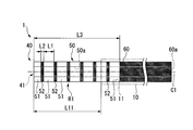
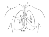
- FIG. 1 is an overall view of an endoscope system according to a first embodiment of the present invention. It is a side view of the guide sheath of the endoscope system. It is an expanded view of the front end side of the guide sheath. It is a figure explaining the procedure which bridge
- FIG. 7 is a cross-sectional view taken along a cutting line AA in FIG. 6. It is a figure explaining the procedure using the endoscope system.
- an endoscope system 1 of the present embodiment includes an endoscope 10 in which an introduction channel 11 is formed, and a guide sheath (long-axis member) that can be inserted into the introduction channel 11. 40.
- the endoscope 10 is configured by providing an operation unit 30 at the base end of a long insertion unit 20.
- the insertion portion 20 includes a distal end hard portion 21 provided at the distal end, a bending portion 22 that can be bent by being connected to the proximal end of the distal end hard portion 21, and a flexible member that is connected to the proximal end of the bending portion 22 and has flexibility. And a tube portion 23.
- An illumination unit 25 having a light emitting element such as an LED and an observation unit 26 having an imaging element such as a CCD are exposed on the distal end surface of the distal end hard portion 21.
- the distal end of the introduction channel 11 has an opening at the distal end surface of the distal end hard portion 21 and extends to the operation portion 30 via the insertion portion 20.
- An operation wire (not shown) is inserted into the insertion portion 20 so as to be able to advance and retract, and the bending portion 22 can be bent in a desired direction by moving the operation wire forward and backward.
- the insertion unit 20 is provided with a power line for supplying power to the illumination unit 25 and the like, and a signal line for transmitting image data acquired by the image sensor.
- the operation unit 30 includes an operation unit main body 31, a forceps port 32 provided on the distal end side of the operation unit main body 31, and a plurality of dials 33 and buttons 34 provided on the proximal end side of the operation unit main body 31. ing.
- the forceps port 32 communicates with the opening on the proximal end side of the introduction channel 11.
- the dial 33 By rotating the dial 33, the bending portion 22 can be bent by operating the operation wire.
- the illumination unit 25 and the observation unit 26 can be operated.
- a universal cable 36 is connected to the operation unit main body 31, and the universal cable 36 is connected to a display device and a power supply device (not shown).
- the power supply device is connected to the illumination unit 25 via a power line, and the display device can display image data transmitted via the signal line as an image.
- the guide sheath 40 is used as a guide for guiding the tip of a medical instrument such as a treatment instrument to a target site in the body.
- the guide sheath 40 is provided at the distal end side and can be bent according to external force, and the flexible support provided at the proximal end side of the bent portion 50.
- the curved portion 50 and the support portion 60 are each formed in a tubular shape. That is, the guide sheath 40 is extended along the axis C1 which is a longitudinal axis of itself.
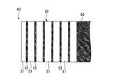
- the curved portion 50 includes a soft portion 51 formed in an annular shape with a flexible material, and a hard portion 52 that is formed in an annular shape and has a bending rigidity larger than that of the soft portion 51. It is comprised by arrange
- the soft part 51 and the hard part 52 are formed to have the same outer diameter and the same inner diameter. In the direction of the axis C1, the length L1 of the soft part 51 is set longer than the length L2 of the hard part 52.
- the to-be-curved part 50 is configured by arranging seven soft parts 51 and six hard parts 52 alternately in the direction of the axis C1.
- the soft part 51 on the most distal side is formed with an opening 41 that allows the medical instrument inserted into the curved part 50 to protrude and retract.
- the soft part 51 is made of a kneaded material in which a thermoplastic resin and a crosslinking accelerator are kneaded.
- a thermoplastic resin that can be used for the soft portion 51, for example, a polyethylene resin, a polybutadiene resin, a thermoplastic aromatic ether aromatic ester resin, a thermoplastic ether amide resin, and the like can be suitably used, but the present invention is not limited thereto. Is not to be done. Further, one type of resin can be used alone, or a plurality of types of resins can be blended and used.
- crosslinking accelerator to be used examples include various polyfunctional monomers. Specific examples include diacrylate compounds such as diethylene glycol, dimethacrylate compounds such as ethylene glycol dimethacrylate, triacrylate compounds such as trimethylolpropane triacrylate, and trimethacrylate compounds such as trimethylolpropane trimethacrylate. And triallyl cyanurate compounds such as triallyl isocyanurate and triallyl cyanurate, diallyl malate, diallyl fumarate, epoxy acrylate, and the like. These can be used alone or in combination of two or more.
- the proportion of the crosslinking accelerator used is 1 to 20 parts by mass, preferably 3 to 10 parts by mass with respect to 100 parts by mass of the thermoplastic aromatic ether ester resin.
- a crosslinking accelerator can be selected within this range according to the required heat resistance performance. In some cases, the kneading material does not require a crosslinking accelerator.
- the hard part 52 is made of a crosslinked material obtained by irradiating the kneaded material with ionizing radiation and crosslinking the thermoplastic resin. It is known that by irradiating the kneaded material with ionizing radiation, the molecules of the thermoplastic resin are cross-linked and the elastic modulus of the resin increases.
- the ionizing radiation used in the present invention include an electron beam, an accelerating electron beam, a ⁇ -ray, an X-ray, an ⁇ -ray, a ⁇ -ray, an ultraviolet ray, and the like. From the viewpoint of industrial use such as the speed of the crosslinking treatment, accelerated electron beams and ⁇ rays can be preferably used.
- the voltage of the accelerating electron beam can be appropriately selected depending on the thickness of the sample.
- the irradiation dose of ionizing radiation is set to, for example, 500 kilogray (kGy) or more.
- the same hatching is given to the members formed of the bridging material.
- the soft part 51 and the hard part 52 have the same cross-sectional shape by a plane orthogonal to the axis C1.
- the elastic modulus of the cross-linking material forming the hard part 52 is larger than the elastic modulus of the kneaded material forming the soft part 51
- the bending rigidity of the hard part 52 is larger than the bending rigidity of the soft part 51.
- the elastic modulus of the cross-linked material is preferably 3 times or more larger than that of the kneaded material.
- the support portion 60 is formed in a tubular shape from the aforementioned bridging material, and is provided over the entire circumference in the circumferential direction of the curved portion 50.
- the support portion 60 and the curved portion 50 are formed to have the same outer diameter and the same inner diameter.
- the bending rigidity of the support part 60 is larger than the bending rigidity of the soft part 51.
- the pipe 60 a of the support part 60 communicates with the pipe 50 a of the curved part 50.
- the channels 50a and 60a form a channel of the guide sheath 40. This channel communicates with the opening 41 described above.
- the outer diameter is 2.5 mm
- the inner diameter is 2.1 mm
- the length is about 1000 mm. It is preferable that an index for indicating the length of the distal end side of the guide sheath 40 protruding from the introduction channel 11 of the endoscope 10 is provided on the outer peripheral surface of the support portion 60.
- the guide sheath 40 configured as described above is used in a state where the distal end side protrudes from the introduction channel 11 of the endoscope 10 as shown in FIG.
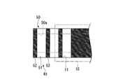
- the length L11 of the guide sheath 40 protruding from the introduction channel 11 in the direction of the axis C1 of the protrusion R1 is about 5 cm to 20 cm, depending on the individual difference of the patient.
- the length L3 of the curved portion 50 in the direction of the axis C1 is set to be 1 cm or longer than the length L11.
- the bent portion 50 is configured to include at least a soft portion 51 and a pair of hard portions 52 that sandwich the soft portion 51 in the direction of the axis C1.
- the length of the guide sheath 40 is set so that the proximal end portion of the guide sheath 40 protrudes from the forceps port 32 toward the proximal end regardless of the length L11 described above.
- a sheath 40 ⁇ / b> A is prepared which is formed in the same shape as the guide sheath 40 with the kneaded material described above.
- a portion of the sheath 40A that is not desired to be cross-linked is covered with a shield S made of lead or the like and irradiated with ionizing radiation Rad.
- the region irradiated with the ionizing radiation Rad is cross-linked to become a cross-linking material, and the hard portion 52 and the support portion 60 are formed.
- the region covered with the shield S becomes a soft portion 51 made of a kneaded material that does not cause cross-linking and retains the characteristics of the thermoplastic resin. Therefore, by appropriately setting the position and length of the region covered with the shield S, the cross-linking material can be formed at a desired position and length of the sheath 40A.
- the inner range R2 that is the inner side of the bending in the soft portion 51 and the hard portion 52 is compressed in the direction of the axis C1, while the outer side that is the outer side of the bending.
- the range R3 is pulled in the direction of the axis C1 and is compressed in the radial direction. This deformation becomes more prominent in the soft portion 51 than in the hard portion 52 due to the difference in bending rigidity.
- the cross-sectional shape orthogonal to the axis C1 of the soft part 51 is substantially elliptical.
- kink that the plastic strain that is recessed toward the conduit 50a remains in the bent portion of the bent portion 50.
- the bending angle ⁇ at which the curved portion 50 is kinked is referred to as “kink angle”.
- the to-be-curved part 50 is easily curved. Moreover, since the soft part 51 and the hard part 52 are each formed in an annular shape, the deformation of the curved part 50 is uniform around the axis C1.
- the protrusion R1 may be subjected to an external force that compresses in the direction of the axis C1, but in this case, the soft part 51 basically only deforms in the direction of the axis C1, so that compared to the case where the protrusion R1 is curved. There is little fear of kinking.
- the operation of the endoscope system 1 will be described in the case where the insertion unit 20 is inserted into the bronchus (target site) of a patient and a procedure is performed endoscopically using several treatment tools.
- the surgeon presses the button 34 to supply power to the illumination unit 25 to illuminate the front of the insertion unit 20 and confirm the image acquired by the observation unit 26 on the display device.
- the insertion portion 20 of the endoscope 10 is inserted into the bronchus P2 through the trachea P1 from the mouth of the patient P, and the dial 33 is rotated as necessary to bend the bending portion 22.
- the distal end of the insertion portion 20 is moved to the vicinity of the tissue to be treated.
- An ultrasonic probe (medical instrument) (not shown) is inserted from the proximal end of the guide sheath 40 outside the patient P's body.
- the guide sheath 40 into which the ultrasonic probe is inserted is inserted into the introduction channel 11 through the forceps port 32 with the curved portion 50 at the distal end, and the guide sheath 40 protrudes from the introduction channel 11 while checking with a display device and an index.
- the length L11 to be adjusted is adjusted.
- the ultrasonic probe is pushed into the guide sheath 40, and the ultrasonic probe is protruded from the distal end of the guide sheath 40.
- the tissue to be treated is searched with an ultrasonic probe, and its position is specified.
- the ultrasonic probe is pulled out from the guide sheath 40.
- the protruding portion R1 mainly withstands the external force. Even in such a case, as shown in FIG. 9, the protruding portion R1 can withstand this external force without kinking.
- the treatment instrument can pass through the guide sheath 40.
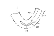
- the curved portion 210 of the guide sheath 200 of the comparative example is entirely made of a kneaded material.
- a portion of the bent portion 210 that protrudes from the insertion portion 20 is bent and kinked by the external force of the bronchus P2.
- the treatment instrument cannot pass through the kinked guide sheath 200.
- a brush-type treatment instrument (medical instrument) W1 is pushed in from the distal end of the guide sheath 40. As shown in FIG. 8, the brush portion W2 of the brush-type treatment instrument W1 is protruded from the distal end of the guide sheath 40, and the tissue is collected by the brush portion W2. The brush type treatment tool W1 is pulled out from the guide sheath 40, and the tissue is collected.
- a biopsy forceps (not shown) or the like is inserted from the proximal end of the guide sheath 40, and appropriate treatment is performed. The biopsy forceps are pulled out from the guide sheath 40, and the guide sheath 40 and the insertion portion 20 are pulled out from the mouth of the patient P to complete a series of procedures.
- the curved portion 50 is configured by alternately arranging the soft portions 51 and the hard portions 52 in the direction of the axis C1.
- the bending rigidity of the soft part 51 is relatively small, the curved part 50 can be easily bent, and the flexibility of the curved part 50 is maintained.
- the hard part 52 supports the soft part 51 which tends to be crushed in the radial direction when the curved part 50 is curved, the curved part 50 is difficult to kink. Therefore, it is possible to easily insert the treatment instrument into the conduit 50a of the curved part 50 to be curved.
- the soft part 51 is made of a kneaded material
- the hard part 52 is made of a cross-linking material.
- the elastic modulus of the kneaded material can be changed by ionizing radiation in a state where the outer diameter and inner diameter are constant along the direction of the axis C1.
- the guide sheath 40 can be easily guided by the introduction channel 11 of the endoscope 10.
- the shape can easily be guided to the distal end through the curved portion 50. Since the soft part 51 and the hard part 52 are each formed in an annular shape, the deformation of the curved part 50 is uniform around the axis C1, and the operator can easily operate the curved part 50.
- the bending rigidity of the support part 60 is larger than the bending rigidity of the soft part 51. For this reason, when the surgeon pushes in the support part 60, it can suppress that the support part 60 curves because the soft part 51 deform
- the endoscope system 1 of the present embodiment includes an endoscope 10 and a guide sheath 40. Thereby, the length L11 of the protrusion R1 of the guide sheath 40 can be confirmed with the endoscope 10.
- the to-be-curved part 50 is configured by the seven soft parts 51 and the six hard parts 52.
- the curved part has at least one soft part 51 and a pair of hard parts 52 sandwiching the soft part 51 in the direction of the axis C1
- the number of the soft parts 51 and the hard parts 52 is not particularly limited. Absent.
- the endoscope system 2 of the present embodiment includes a guide sheath 80 instead of the guide sheath 40 of the endoscope system 1 of the first embodiment.
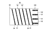
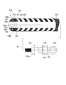
- the guide sheath 80 has a curved portion 90 disposed on the distal end side when inserted through the introduction channel 11 and a support portion 100 provided on the proximal end side of the curved portion 90.
- the curved portion 90 is disposed between a soft portion 92 in which a linear body 91 made of the kneading material is wound in a spiral around the axis C2, and a linear body 91 adjacent in the direction of the axis C2. And a hard portion 93 formed in a spiral shape.
- the hard part 93 is made of the aforementioned cross-linking material.
- the linear body 91 and the linear body 94 constituting the hard portion 93 are arranged alternately in the direction of the axis C2.
- the soft portion 92 and the hard portion 93 are formed to have the same outer diameter and the same inner diameter.
- the flexible body 92 is formed by winding the linear body 91 about the axis C ⁇ b> 2 about 7 times, and the linear body 94 is formed about 6 times around the axis C ⁇ b> 2.
- the hard part 93 is formed by being wound.
- at least the linear body 91 is arranged in a spiral shape around the axis C2, and the linear bodies 94 are arranged in a state of sandwiching the linear body 91 in the direction of the axis C2. It is formed into a shape.
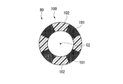
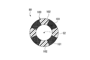
- the support portion 100 is formed so as to extend in the direction of the axis C2, and is adjacent to the four proximal-side hard portions 101 disposed so as to be separated from each other in the circumferential direction D2 of the curved portion 90, in the circumferential direction D2. It has four base end side soft parts 102 arranged between the base end side hard parts 101.
- the proximal end side hard portion 101 is made of the aforementioned cross-linking material, and the proximal end side soft portion 102 is made of the aforementioned kneading material.
- the support portion 100 including the four base end side hard portions 101 and the four base end side soft portions 102 is formed in a tubular shape.
- the support part 100 and the to-be-curved part 90 are formed to have the same outer diameter and the same inner diameter.
- the pipe line 100 a of the support part 100 communicates with the pipe line 90 a of the curved part 90.
- the curved portion 90 in the guide sheath 80 of the present embodiment is difficult to kink while maintaining flexibility by the same action as the curved portion 50 of the first embodiment described above. Moreover, since the support part 100 consists of a kneading
- the guide sheath 80 of this embodiment can be manufactured in the same manner as the guide sheath 40 of the first embodiment by adjusting the shape of the shield.
- the cross-sectional shape by a plane orthogonal to the axis C2 is circular as shown in FIG.
- the end side soft parts 102 each have an arc shape.
- the proximal end side hard portion 101 is hardly deformed due to a difference in elastic modulus, and the proximal end side soft portion 102 is compressed as shown in FIG.
- the support part 100 is reduced in diameter.
- the support portion 100 is expanded in diameter by being deformed so that the proximal end side soft portion 102 spreads outward.
- the curved portion 90 can be made difficult to kink while maintaining the flexibility of the curved portion 90. Since the bending rigidity of the support part 100 is smaller than that of the hard part 93, it is possible to suppress the deformation of the support part 100 and the buckling of the hard part 93 due to the reaction force from the tissue. . Since the support part 100 is comprised by the base end side hard part 101 and the base end side soft part 102, the diameter of the support part 100 can be easily reduced or expanded.
- the guide sheath 110 of the present embodiment is provided on the distal end side and can be bent according to external force, and is provided on the proximal end side of the bent portion 120 and is flexible.
- Each of the curved portion 120 and the support portion 130 is formed in a tubular shape.
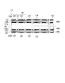
- the curved portion 120 is formed with a first curved portion-side conduit 120a extending along the longitudinal direction of the guide sheath 110, and second curved portion-side conduits 120b and 120c.
- the first curved portion side duct 120 a is formed on the central axis C ⁇ b> 4 of the guide sheath 110.
- the second curved portion side ducts 120b and 120c are formed so as to have a smaller diameter than the first curved portion side duct 120a and sandwich the first curved portion side duct 120a. That is, the second curved portion side ducts 120b and 120c are formed so as to be displaced in the radial direction of the guide sheath 110 with respect to the central axis C4.
- the to-be-curved part 120 has a configuration in which a soft part 121 formed in a tubular shape is provided with a plurality of hard parts 122 spaced apart from each other in the longitudinal direction.
- the hard part 122 is formed in a plate shape having a substantially semicircular shape when viewed in parallel with the longitudinal direction.
- the hard portion 122 is disposed so as to sandwich the central axis C4.
- the hard part 122 is also provided on the distal end surface 121 a of the soft part 121.
- the soft part 121 is made of a kneaded material in which a thermoplastic resin and a crosslinking accelerator are kneaded, like the soft part 51 described above.
- thermoplastic resin for example, a low density polyethylene resin (LDPE) can be suitably used.
- LDPE low density polyethylene resin
- crosslinking accelerator triallyl isocyanurate can be suitably used.
- the hard portion 122 is formed by irradiating this kneaded material with ionizing radiation and crosslinking. The hardness and breaking strength of the hard part 122 are higher than that of the soft part 121.
- An operation wire tip (fixing member) 125 is fixed to the distal end portion of the second bent portion side ducts 120b and 120c.
- the operation wire tip 125 can be formed of a metal such as stainless steel or a hard resin.
- the operation wire tip 125 is provided on the distal end surface 121a of the soft portion 121 constituting the second bent portion side ducts 120b and 120c, for example, by being press-fitted into the second bent portion side ducts 120b and 120c.
- the hard part 122 is fixed.
- Operation wires 126 and 127 are arranged in the second curved portion side pipe lines 120b and 120c, respectively.
- the tips of the operation wires 126 and 127 are fixed to the operation wire tip 125. That is, the distal ends of the operation wires 126 and 127 are fixed to the cross-linked hard portion 122 by the operation wire tip 125. Therefore, the vicinity of the operation wire tip 125 in the to-be-curved part 120, and between the second to-be-curved part side conduits 120b and 120c and the outer peripheral surface in the to-be-curved part 120 to which the operation wires 126 and 127 are fixed. It is possible to prevent tearing or breaking of the tip of the partition wall 120d.
- the partition wall 120d referred to here is between the outer peripheral surface of the curved portion 120 and the second curved portion-side duct 120b, and between the outer circumferential surface of the curved portion 120 and the second curved portion-side duct 120c. It is a portion between the two, and means a portion in a range extending over the entire length of the curved portion 120. Note that the distal end portions of the operation wires 126 and 127 are directly fixed to the hard portion 122 provided on the distal end surface 121a without providing the operation wire tip 125 at the distal end portions of the second curved portion side ducts 120b and 120c. May be.
- the support part 130 is formed in the same shape as the to-be-curved part 120 in a cross section by a plane orthogonal to the longitudinal direction. That is, the support part 130 is formed with a first support part side pipe line 130a and second support part side pipe lines 130b and 130c extending along the longitudinal direction.
- the support part 130 is formed by irradiating ionizing radiation to a kneaded material in which a thermoplastic resin such as a high density polyethylene resin (HDPE) and a crosslinking accelerator are kneaded and crosslinking.
- the to-be-curved part 120 and the support part 130 are joined by an adhesive or the like.
- the bending rigidity of the curved part 120 is smaller than the bending rigidity of the support part 130.
- the first support portion side conduit 130a and the second support portion side conduits 130b and 130c communicate with the first bent portion side conduit 120a and the second bent portion side conduits 120b and 120c, respectively.
- the second channel is constituted by the second curved portion side duct 120b and the second supporting portion side duct 130b, the second curved portion side duct 120c and the second supporting portion side duct 130c. To do.
- the operation unit 140 has a known configuration, and includes a tubular operation unit shaft 141 fixed to the base end portion of the support unit 130, and sliders 142 and 143 provided on the operation unit shaft 141 so as to be slidable in the longitudinal direction. And.
- a main port 141 a that communicates with the first support portion side pipe line 130 a of the support portion 130 is provided at the distal end portion of the operation portion shaft 141.
- a thumb ring 141 b is attached to the proximal end portion of the operation portion shaft 141.
- the sliders 142 and 143 are connected to the operation wires 126 and 127, respectively.
- the sliders 142 and 143 can slide independently of each other.
- the guide sheath 110 configured as described above holds the operation unit 140 by placing the thumb on the thumb ring 141b and the index finger and the middle finger on the sliders 142 and 143. As shown in FIG. 17, when the slider 142 is moved to the proximal end side in the longitudinal direction with respect to the operation portion shaft 141 (retracted) from the straight state of the curved portion 120 and the support portion 130, the operation wire 126 is moved to the base. Move to the end side.
- the operation wire tip 125 fixed to the operation wire 126 moves to the proximal end side, but the support portion 130 having a large bending rigidity is not deformed so much that the soft portion 121 of the curved portion 120 is compressed in the longitudinal direction,
- the to-be-curved portion 120 is bent so that the operation wire 126 side is on the inside.
- the operation wire 126 comes into contact with the inner surface of the partition wall 120d on the operation wire 126 side over almost the entire length of the curved portion 120. Since the curved portion 120 is provided with a plurality of hard portions 122, when the bending portion 120 is bent by pulling the operating wire 126 to the proximal end side, the partition wall 120 d on the operating wire 126 side is torn and the operating wire is broken.
- the guide sheath 110 of the present embodiment configured as described above, it is possible to make it difficult to kink while maintaining the flexibility of the curved portion 120. Since the curved portion 120 is provided with the hard portion 122, the operation wires 126 and 127 can be pulled back without damaging the partition wall 120d of the curved portion 120. The distal ends of the operation wires 126 and 127 are fixed to the hard portion 122 via the operation wire tip 125. Since the bending rigidity of the hard part 122 is larger than that of the soft part 121, it is possible to prevent the operation wire tip 125 from coming out of the curved part 120 and to securely fix the distal ends of the operation wires 126 and 127 to the curved part 120. it can. Since the outer diameter of the curved portion 120 and the support portion 130 is constant regardless of the position in the longitudinal direction, the outer peripheral surfaces of the curved portion 120 and the support portion 130 are not uneven.
- the guide sheath 110 includes the operation unit 140, but the guide sheath 110 may not include the operation unit 140. This is because the curved portion 120 can be bent by pulling back the operation wires 126 and 127 with respect to the support portion 130.
- first to third embodiments of the present invention have been described in detail with reference to the drawings. However, the specific configuration is not limited to this embodiment, and the configuration does not depart from the gist of the present invention. Changes are also included. Furthermore, it goes without saying that the configurations shown in the embodiments can be used in appropriate combinations.
- an additive that improves the toughness of the soft material may be included in the kneaded material.
- the term “toughness” as used herein is synonymous with brittleness, and means a property that causes significant elongation or deformation of the drawing when the material is stretched. “Improving toughness” means that the material is easily stretched or deformed.
- additives examples include HDPE (High Density Polyethylene), LDPE (Low Density Polyethylene), EVA (Ethylene-Vinyl Acetate: ethylene-vinyl acetate copolymer resin), and carbon (carbon). , And combinations thereof can be appropriately selected and used.
- HDPE High Density Polyethylene
- LDPE Low Density Polyethylene
- EVA Ethylene-Vinyl Acetate: ethylene-vinyl acetate copolymer resin
- carbon carbon
- the length of the soft part may be set equal to the length of the hard part, or may be set shorter than the length of the hard part. These lengths can be appropriately set based on the bending angle ⁇ of the portion to be bent. Moreover, when it is desired to increase the bending rigidity of the support portion, the ratio of bridging the support portion may be increased, or a reinforcing member may be attached to the outer surface or the inner surface of the support portion.
- the insertion part 20 of the endoscope system is inserted into the lung through the mouth of the patient P.
- the part into which the insertion unit 20 is inserted is not limited to the lung, and may be, for example, a luminal organ such as the esophagus, duodenum, small intestine, large intestine, uterus, bladder, and blood vessels.
- the intracorporeal instrument is an endoscope
- the intracorporeal instrument is not limited to an endoscope, and may be, for example, an overtube.
- the present invention is not limited by the above description, and is limited only by the scope of the appended claims.
Landscapes
- Health & Medical Sciences (AREA)
- Life Sciences & Earth Sciences (AREA)
- Surgery (AREA)
- Biomedical Technology (AREA)
- Medical Informatics (AREA)
- Optics & Photonics (AREA)
- Pathology (AREA)
- Radiology & Medical Imaging (AREA)
- Biophysics (AREA)
- Engineering & Computer Science (AREA)
- Physics & Mathematics (AREA)
- Heart & Thoracic Surgery (AREA)
- Nuclear Medicine, Radiotherapy & Molecular Imaging (AREA)
- Molecular Biology (AREA)
- Animal Behavior & Ethology (AREA)
- General Health & Medical Sciences (AREA)
- Public Health (AREA)
- Veterinary Medicine (AREA)
- Media Introduction/Drainage Providing Device (AREA)
- Surgical Instruments (AREA)
Abstract
Priority Applications (4)
| Application Number | Priority Date | Filing Date | Title |
|---|---|---|---|
| EP13757105.5A EP2823768B1 (fr) | 2012-03-08 | 2013-02-18 | Manchon de guidage et système médical |
| CN201380003888.8A CN103930044B (zh) | 2012-03-08 | 2013-02-18 | 引导护套及医疗系统 |
| JP2013545569A JP5509392B2 (ja) | 2012-03-08 | 2013-02-18 | ガイドシース |
| US14/043,987 US8911359B2 (en) | 2012-03-08 | 2013-10-02 | Guide sheath and medical system |
Applications Claiming Priority (2)
| Application Number | Priority Date | Filing Date | Title |
|---|---|---|---|
| US201261608280P | 2012-03-08 | 2012-03-08 | |
| US61/608,280 | 2012-03-08 |
Related Child Applications (1)
| Application Number | Title | Priority Date | Filing Date |
|---|---|---|---|
| US14/043,987 Continuation US8911359B2 (en) | 2012-03-08 | 2013-10-02 | Guide sheath and medical system |
Publications (1)
| Publication Number | Publication Date |
|---|---|
| WO2013132992A1 true WO2013132992A1 (fr) | 2013-09-12 |
Family
ID=49116476
Family Applications (1)
| Application Number | Title | Priority Date | Filing Date |
|---|---|---|---|
| PCT/JP2013/053809 Ceased WO2013132992A1 (fr) | 2012-03-08 | 2013-02-18 | Manchon de guidage et système médical |
Country Status (5)
| Country | Link |
|---|---|
| US (1) | US8911359B2 (fr) |
| EP (1) | EP2823768B1 (fr) |
| JP (1) | JP5509392B2 (fr) |
| CN (1) | CN103930044B (fr) |
| WO (1) | WO2013132992A1 (fr) |
Cited By (14)
| Publication number | Priority date | Publication date | Assignee | Title |
|---|---|---|---|---|
| CN104799807A (zh) * | 2015-04-24 | 2015-07-29 | 姚鹏 | 一次性软质输尿管导管 |
| CN109330565A (zh) * | 2018-10-29 | 2019-02-15 | 山东大学 | 一种测量肺泡气压的光纤传感探头 |
| JP6504424B1 (ja) * | 2017-12-27 | 2019-04-24 | オリンパス株式会社 | 医療機器および医療システム |
| WO2019130650A1 (fr) * | 2017-12-27 | 2019-07-04 | オリンパス株式会社 | Dispositif médical et système médical |
| JP2022052257A (ja) * | 2020-09-23 | 2022-04-04 | 富士フイルム株式会社 | 内視鏡用処置具装置及び内視鏡システム |
| WO2023120255A1 (fr) * | 2021-12-24 | 2023-06-29 | 富士フイルム株式会社 | Gaine de couverture, dispositif d'outil de traitement endoscopique et instrument endoscopique |
| JP2023529307A (ja) * | 2020-05-26 | 2023-07-10 | ネプチューン メディカル インク. | 剛性付与デバイス |
| JP2024029647A (ja) * | 2022-08-22 | 2024-03-06 | 株式会社カネカ | カテーテル、およびカテーテルを有する内視鏡 |
| US12330292B2 (en) | 2023-09-28 | 2025-06-17 | Neptune Medical Inc. | Telescoping robot |
| US12458210B2 (en) | 2023-09-07 | 2025-11-04 | Neptune Medical Inc. | Pressure rigidization apparatuses and methods |
| US12514431B2 (en) | 2018-05-31 | 2026-01-06 | Neptune Medical Inc. | Devices and methods for enhanced visualization of body cavities |
| US12539624B2 (en) | 2021-03-10 | 2026-02-03 | Neptune Medical Inc. | Nested dynamically rigidizing robotic systems |
| US12564312B2 (en) | 2022-04-19 | 2026-03-03 | Neptune Medical Inc. | Managing and manipulating a long length robotic endoscope |
| US12616358B2 (en) | 2022-04-27 | 2026-05-05 | Neptune Medical Inc. | Rigidizing sheath apparatus for an endoscope |
Families Citing this family (8)
| Publication number | Priority date | Publication date | Assignee | Title |
|---|---|---|---|---|
| EP3155952B1 (fr) * | 2014-06-10 | 2019-10-02 | Olympus Corporation | Système de biopsie |
| WO2016143142A1 (fr) * | 2015-03-12 | 2016-09-15 | 学校法人慶應義塾 | Aide d'introduction d'instrument de traitement |
| CN113288514B (zh) * | 2016-12-16 | 2024-12-24 | 爱德华兹生命科学公司 | 用于递送假体瓣膜用锚定装置的部署系统、工具和方法 |
| WO2018229925A1 (fr) * | 2017-06-15 | 2018-12-20 | オリンパス株式会社 | Cathéter |
| CN111194178B (zh) * | 2017-10-02 | 2022-06-17 | 奥林巴斯株式会社 | 内窥镜 |
| WO2019202699A1 (fr) * | 2018-04-19 | 2019-10-24 | オリンパス株式会社 | Dispositif médical |
| US12042166B2 (en) | 2020-09-22 | 2024-07-23 | Boston Scientific Medical Device Limited | Medical articulation devices and methods of using the same |
| CN116602603B (zh) * | 2023-07-20 | 2023-09-15 | 中日友好医院(中日友好临床医学研究所) | 一种直工作通道可弯曲胸腔镜套件 |
Citations (9)
| Publication number | Priority date | Publication date | Assignee | Title |
|---|---|---|---|---|
| JPS58108801U (ja) * | 1982-01-14 | 1983-07-25 | 旭光学工業株式会社 | 内視鏡 |
| JPS61171902U (fr) * | 1985-04-15 | 1986-10-25 | ||
| JPH0210802U (fr) * | 1988-07-05 | 1990-01-24 | ||
| JPH03280918A (ja) * | 1990-03-28 | 1991-12-11 | Olympus Optical Co Ltd | 内視鏡 |
| JPH0857035A (ja) | 1994-08-24 | 1996-03-05 | Terumo Corp | カテーテルチューブおよびその製造方法 |
| JP2005287963A (ja) * | 2004-04-02 | 2005-10-20 | Olympus Corp | 内視鏡治療装置 |
| JP2007289467A (ja) * | 2006-04-26 | 2007-11-08 | Pentax Corp | 内視鏡の処置具挿通チャンネル |
| JP4624483B2 (ja) | 2008-12-22 | 2011-02-02 | オリンパスメディカルシステムズ株式会社 | 処置具 |
| WO2012005124A1 (fr) * | 2010-07-05 | 2012-01-12 | オリンパスメディカルシステムズ株式会社 | Tube à disposer dans des endoscopes, et endoscope |
Family Cites Families (14)
| Publication number | Priority date | Publication date | Assignee | Title |
|---|---|---|---|---|
| JPS58108801A (ja) | 1981-12-22 | 1983-06-29 | Matsushita Electric Ind Co Ltd | 同軸型誘電体共振器 |
| JPS61171902A (ja) | 1985-01-22 | 1986-08-02 | Kobe Steel Ltd | 複数アクチユエ−タの油圧制御回路 |
| JPH0210802A (ja) | 1988-06-29 | 1990-01-16 | Matsushita Electric Ind Co Ltd | バリスタ |
| US5562601A (en) * | 1994-05-27 | 1996-10-08 | Takada; Masazumi | Self-propelled colonoscope |
| US5921915A (en) * | 1997-04-30 | 1999-07-13 | C.R. Bard, Inc. | Directional surgical device for use with endoscope, gastroscope, colonoscope or the like |
| JP2001050435A (ja) * | 1999-08-09 | 2001-02-23 | Toyo Tire & Rubber Co Ltd | 複合可とう管及びその製造方法 |
| US7645287B2 (en) * | 2005-05-03 | 2010-01-12 | Ethicon Endo-Surgery, Inc. | Articulating anastomotic ring applier |
| US8246536B2 (en) * | 2006-04-26 | 2012-08-21 | Hoya Corporation | Treatment tool insertion channel of endoscope |
| WO2009062150A1 (fr) * | 2007-11-11 | 2009-05-14 | Imacor Llc | Sonde transœsophagienne à ultrasons avec section de flexion adaptative |
| EP2474267A4 (fr) * | 2009-09-04 | 2017-04-12 | Terumo Kabushiki Kaisha | Cathéter |
| WO2011100052A1 (fr) * | 2010-02-11 | 2011-08-18 | Ai Medical Devices, Inc. | Dispositif d'intubation épousant la forme |
| JP5591043B2 (ja) * | 2010-09-22 | 2014-09-17 | 富士フイルム株式会社 | 内視鏡及びその軟性部 |
| EP2508117B1 (fr) * | 2010-09-30 | 2015-04-01 | Olympus Medical Systems Corp. | Aide à l'introduction et dispositif d'endoscope |
| US20130178703A1 (en) * | 2012-01-05 | 2013-07-11 | Gyrus Acmi, Inc. | Endoscope Shaft With Malleable Section |
-
2013
- 2013-02-18 JP JP2013545569A patent/JP5509392B2/ja active Active
- 2013-02-18 CN CN201380003888.8A patent/CN103930044B/zh active Active
- 2013-02-18 WO PCT/JP2013/053809 patent/WO2013132992A1/fr not_active Ceased
- 2013-02-18 EP EP13757105.5A patent/EP2823768B1/fr not_active Not-in-force
- 2013-10-02 US US14/043,987 patent/US8911359B2/en active Active
Patent Citations (9)
| Publication number | Priority date | Publication date | Assignee | Title |
|---|---|---|---|---|
| JPS58108801U (ja) * | 1982-01-14 | 1983-07-25 | 旭光学工業株式会社 | 内視鏡 |
| JPS61171902U (fr) * | 1985-04-15 | 1986-10-25 | ||
| JPH0210802U (fr) * | 1988-07-05 | 1990-01-24 | ||
| JPH03280918A (ja) * | 1990-03-28 | 1991-12-11 | Olympus Optical Co Ltd | 内視鏡 |
| JPH0857035A (ja) | 1994-08-24 | 1996-03-05 | Terumo Corp | カテーテルチューブおよびその製造方法 |
| JP2005287963A (ja) * | 2004-04-02 | 2005-10-20 | Olympus Corp | 内視鏡治療装置 |
| JP2007289467A (ja) * | 2006-04-26 | 2007-11-08 | Pentax Corp | 内視鏡の処置具挿通チャンネル |
| JP4624483B2 (ja) | 2008-12-22 | 2011-02-02 | オリンパスメディカルシステムズ株式会社 | 処置具 |
| WO2012005124A1 (fr) * | 2010-07-05 | 2012-01-12 | オリンパスメディカルシステムズ株式会社 | Tube à disposer dans des endoscopes, et endoscope |
Non-Patent Citations (1)
| Title |
|---|
| See also references of EP2823768A4 |
Cited By (17)
| Publication number | Priority date | Publication date | Assignee | Title |
|---|---|---|---|---|
| CN104799807A (zh) * | 2015-04-24 | 2015-07-29 | 姚鹏 | 一次性软质输尿管导管 |
| JP6504424B1 (ja) * | 2017-12-27 | 2019-04-24 | オリンパス株式会社 | 医療機器および医療システム |
| WO2019130650A1 (fr) * | 2017-12-27 | 2019-07-04 | オリンパス株式会社 | Dispositif médical et système médical |
| US12514431B2 (en) | 2018-05-31 | 2026-01-06 | Neptune Medical Inc. | Devices and methods for enhanced visualization of body cavities |
| CN109330565A (zh) * | 2018-10-29 | 2019-02-15 | 山东大学 | 一种测量肺泡气压的光纤传感探头 |
| CN109330565B (zh) * | 2018-10-29 | 2020-04-24 | 山东大学 | 一种测量肺泡气压的光纤传感探头 |
| JP7824891B2 (ja) | 2020-05-26 | 2026-03-05 | ネプチューン メディカル インク. | 剛性付与デバイス |
| JP2023529307A (ja) * | 2020-05-26 | 2023-07-10 | ネプチューン メディカル インク. | 剛性付与デバイス |
| JP2022052257A (ja) * | 2020-09-23 | 2022-04-04 | 富士フイルム株式会社 | 内視鏡用処置具装置及び内視鏡システム |
| US12539624B2 (en) | 2021-03-10 | 2026-02-03 | Neptune Medical Inc. | Nested dynamically rigidizing robotic systems |
| WO2023120255A1 (fr) * | 2021-12-24 | 2023-06-29 | 富士フイルム株式会社 | Gaine de couverture, dispositif d'outil de traitement endoscopique et instrument endoscopique |
| US12564312B2 (en) | 2022-04-19 | 2026-03-03 | Neptune Medical Inc. | Managing and manipulating a long length robotic endoscope |
| US12616358B2 (en) | 2022-04-27 | 2026-05-05 | Neptune Medical Inc. | Rigidizing sheath apparatus for an endoscope |
| JP2024029647A (ja) * | 2022-08-22 | 2024-03-06 | 株式会社カネカ | カテーテル、およびカテーテルを有する内視鏡 |
| US12458210B2 (en) | 2023-09-07 | 2025-11-04 | Neptune Medical Inc. | Pressure rigidization apparatuses and methods |
| US12330292B2 (en) | 2023-09-28 | 2025-06-17 | Neptune Medical Inc. | Telescoping robot |
| US12564973B2 (en) | 2023-09-28 | 2026-03-03 | Neptune Medical Inc. | Telescoping robot |
Also Published As
| Publication number | Publication date |
|---|---|
| US20140094658A1 (en) | 2014-04-03 |
| EP2823768A4 (fr) | 2016-01-06 |
| CN103930044B (zh) | 2016-05-18 |
| CN103930044A (zh) | 2014-07-16 |
| US8911359B2 (en) | 2014-12-16 |
| EP2823768B1 (fr) | 2017-11-29 |
| JP5509392B2 (ja) | 2014-06-04 |
| JPWO2013132992A1 (ja) | 2015-07-30 |
| EP2823768A1 (fr) | 2015-01-14 |
Similar Documents
| Publication | Publication Date | Title |
|---|---|---|
| JP5509392B2 (ja) | ガイドシース | |
| US8579802B2 (en) | Flexible endoscope with modifiable stiffness | |
| JP7702487B2 (ja) | 操縦可能機器の中央ルーメンの強化 | |
| JP7560133B2 (ja) | 医療器具用の挿入ユニット及びその挿管システム | |
| US20120172667A1 (en) | Endoscope tube and endoscope apparatus | |
| JP2016140695A (ja) | 内視鏡システム | |
| JP6444809B2 (ja) | 内視鏡システム | |
| JP3775831B2 (ja) | カテーテルチューブ | |
| EP3269288B1 (fr) | Aide d'introduction d'instrument de traitement | |
| JP3780066B2 (ja) | 医療用チューブ | |
| JPH10328306A (ja) | 医療用チューブ | |
| JP3549264B2 (ja) | カテーテルチューブ | |
| JPH09266881A (ja) | カテーテルチューブ | |
| US20190282068A1 (en) | Mini-scope apparatus and system and method of use thereof | |
| JP3632932B2 (ja) | カテーテルチューブ | |
| JP2005305185A (ja) | 医療用チューブ | |
| JP2010110444A (ja) | 内視鏡の可撓管 | |
| CN113164709B (zh) | 用于能量递送的内窥镜系统 | |
| CN222533252U (zh) | 内窥镜用软管及内窥镜 | |
| JPH09154950A (ja) | カテーテルチューブ | |
| US20200375442A1 (en) | Endoscope with bonded light guide | |
| WO2007032085A1 (fr) | Auxiliaire d’insertion | |
| JP2010042120A (ja) | 内視鏡 | |
| JP2019000175A (ja) | 超音波内視鏡 |
Legal Events
| Date | Code | Title | Description |
|---|---|---|---|
| ENP | Entry into the national phase |
Ref document number: 2013545569 Country of ref document: JP Kind code of ref document: A |
|
| 121 | Ep: the epo has been informed by wipo that ep was designated in this application |
Ref document number: 13757105 Country of ref document: EP Kind code of ref document: A1 |
|
| NENP | Non-entry into the national phase |
Ref country code: DE |
|
| REEP | Request for entry into the european phase |
Ref document number: 2013757105 Country of ref document: EP |
|
| WWE | Wipo information: entry into national phase |
Ref document number: 2013757105 Country of ref document: EP |