WO2014141509A1 - Conduite d'échappement - Google Patents
Conduite d'échappement Download PDFInfo
- Publication number
- WO2014141509A1 WO2014141509A1 PCT/JP2013/074262 JP2013074262W WO2014141509A1 WO 2014141509 A1 WO2014141509 A1 WO 2014141509A1 JP 2013074262 W JP2013074262 W JP 2013074262W WO 2014141509 A1 WO2014141509 A1 WO 2014141509A1
- Authority
- WO
- WIPO (PCT)
- Prior art keywords
- exhaust
- porous region
- open end
- wall portion
- main body
- Prior art date
- Legal status (The legal status is an assumption and is not a legal conclusion. Google has not performed a legal analysis and makes no representation as to the accuracy of the status listed.)
- Ceased
Links
Images







Classifications
-
- F—MECHANICAL ENGINEERING; LIGHTING; HEATING; WEAPONS; BLASTING
- F02—COMBUSTION ENGINES; HOT-GAS OR COMBUSTION-PRODUCT ENGINE PLANTS
- F02C—GAS-TURBINE PLANTS; AIR INTAKES FOR JET-PROPULSION PLANTS; CONTROLLING FUEL SUPPLY IN AIR-BREATHING JET-PROPULSION PLANTS
- F02C7/00—Features, components parts, details or accessories, not provided for in, or of interest apart form groups F02C1/00 - F02C6/00; Air intakes for jet-propulsion plants
- F02C7/24—Heat or noise insulation
-
- F—MECHANICAL ENGINEERING; LIGHTING; HEATING; WEAPONS; BLASTING
- F01—MACHINES OR ENGINES IN GENERAL; ENGINE PLANTS IN GENERAL; STEAM ENGINES
- F01D—NON-POSITIVE DISPLACEMENT MACHINES OR ENGINES, e.g. STEAM TURBINES
- F01D25/00—Component parts, details, or accessories, not provided for in, or of interest apart from, other groups
- F01D25/30—Exhaust heads, chambers, or the like
-
- F—MECHANICAL ENGINEERING; LIGHTING; HEATING; WEAPONS; BLASTING
- F23—COMBUSTION APPARATUS; COMBUSTION PROCESSES
- F23R—GENERATING COMBUSTION PRODUCTS OF HIGH PRESSURE OR HIGH VELOCITY, e.g. GAS-TURBINE COMBUSTION CHAMBERS
- F23R3/00—Continuous combustion chambers using liquid or gaseous fuel
- F23R3/002—Wall structures
-
- F—MECHANICAL ENGINEERING; LIGHTING; HEATING; WEAPONS; BLASTING
- F05—INDEXING SCHEMES RELATING TO ENGINES OR PUMPS IN VARIOUS SUBCLASSES OF CLASSES F01-F04
- F05D—INDEXING SCHEME FOR ASPECTS RELATING TO NON-POSITIVE-DISPLACEMENT MACHINES OR ENGINES, GAS-TURBINES OR JET-PROPULSION PLANTS
- F05D2260/00—Function
- F05D2260/94—Functionality given by mechanical stress related aspects such as low cycle fatigue [LCF] of high cycle fatigue [HCF]
-
- F—MECHANICAL ENGINEERING; LIGHTING; HEATING; WEAPONS; BLASTING
- F23—COMBUSTION APPARATUS; COMBUSTION PROCESSES
- F23J—REMOVAL OR TREATMENT OF COMBUSTION PRODUCTS OR COMBUSTION RESIDUES; FLUES
- F23J2213/00—Chimneys or flues
- F23J2213/50—Top cover
-
- F—MECHANICAL ENGINEERING; LIGHTING; HEATING; WEAPONS; BLASTING
- F23—COMBUSTION APPARATUS; COMBUSTION PROCESSES
- F23J—REMOVAL OR TREATMENT OF COMBUSTION PRODUCTS OR COMBUSTION RESIDUES; FLUES
- F23J2900/00—Special arrangements for conducting or purifying combustion fumes; Treatment of fumes or ashes
- F23J2900/13003—Means for reducing the noise in smoke conducing ducts or systems
Definitions
- the present invention relates to an exhaust flue for discharging exhaust gas from a gas turbine, for example.
- General gas turbine is composed of a compressor, a combustor, and a turbine. Then, the air taken in from the air duct is compressed by the compressor to become high-temperature and high-pressure compressed air. In the combustor, fuel is supplied to the compressed air and burned, and the high-temperature and high-pressure air is burned. A combustion gas (working fluid) is obtained, a turbine is driven by the combustion gas, and a generator connected to the turbine is driven.
- the exhaust flue for discharging the exhaust gas of such a gas turbine may emit sound having a low frequency component of several Hz or less to the outside due to resonance of the sound field inside the gas turbine.
- low-frequency component sounds often have frequencies below human audible sounds, so it is less likely to feel abnormal noise directly, but indirectly causes rattling of the window frames of houses around the plant.
- the exhaust flue silencer of Patent Document 1 described above can reduce the sound of low frequency components. However, in the exhaust flue described in Patent Document 1, it is necessary to enlarge the silencer in order to reduce the resonance vibration of the low-frequency sound field below the audible sound, and it takes time and cost to install the silencer. .
- This invention solves the subject mentioned above, and aims at providing the exhaust flue which suppresses discharge
- the exhaust flue has an exhaust chimney body that is a passage for exhaust gas exhaust, and an open end porous body that has a plurality of holes along the entire circumference of the open end side of the exhaust chimney body. And a region.
- the exhaust flue can reduce the possibility of indirectly causing vibrations such as window frames of houses around the plant.
- the exhaust flue only needs to open a plurality of holes along the entire periphery of the open end in the exhaust chimney body, so the construction period is short and the construction cost can be reduced.
- the exhaust chimney body is provided with another porous region having a plurality of holes at a position different from the open end porous region.
- an outer cylinder portion that covers the outer peripheral side of the open end porous region with a gap.
- the exhaust chimney main body preferably includes a reinforcing rib between adjacent holes in the open end porous region or between adjacent holes in the other porous region.
- the exhaust flue can suppress reflection of resonance vibration in the exhaust chimney main body and maintain the strength of the exhaust chimney main body at a certain level or more.
- the exhaust chimney main body includes an outer wall portion, an inner wall portion, a connecting member that connects the outer wall portion and the inner wall portion, and a heat insulating material interposed between the outer wall portion and the inner wall portion. It is preferable that the hole is formed through the outer wall portion, the heat insulating material, and the inner wall portion.
- the hole is preferably configured so that a cylindrical member passes through the outer wall portion, the heat insulating material, and the inner wall portion.
- the hole is formed by the cylindrical member, the structure can be simplified, and exhaust gas can be prevented from entering between the outer wall portion and the inner wall portion to improve durability. be able to.
- a lower end and an upper end of the gap provided between the open end porous region and the outer cylinder portion are opened to the outside.
- the exhaust gas discharged from the exhaust chimney main body through the hole into the gap is mixed with the outside air that has entered from the lower end of the gap and cooled. Thereafter, the exhaust gas after cooling rises through the air gap and is discharged from the upper end, so that the high temperature of the outer wall portion can be suppressed.
- the outer cylinder portion is provided with a heat insulating material on an inner surface facing the hole.
- the exhaust gas discharged from the exhaust chimney main body through the hole into the air gap rises after colliding with the heat insulating material, and the high temperature of the outer wall portion can be suppressed.
- the outer cylinder portion is provided with a rib on the outer surface.
- a plurality of porous structural blocks each having a cylindrical shape having a predetermined length are connected to each other.
- a plurality of porous structure blocks are manufactured in a factory, the plurality of porous structure blocks are transported to the site, and a plurality of porous structure blocks are connected to manufacture an exhaust flue. Simplification is possible and construction costs can be reduced.
- the exhaust chimney includes an exhaust chimney main body that is a passage for exhaust gas exhaust, and an open end porous region having a plurality of holes in at least a part of the entire periphery on the open end side of the exhaust chimney main body. It is characterized by including.
- the exhaust flue can reduce the possibility of indirectly causing vibrations such as window frames of houses around the plant.
- the open end porous region is preferably provided on the open end side inside the bending direction of the exhaust chimney main body.
- FIG. 1 is a schematic configuration diagram illustrating a gas turbine according to the first embodiment.
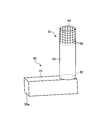
- FIG. 2 is a perspective view schematically showing the exhaust flue of the first embodiment.
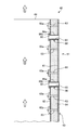
- FIG. 3 is a partial cross-sectional view schematically showing an open end porous region cut by a cross section passing through the center of the hole in FIG. 2.
- FIG. 4 is an explanatory diagram for explaining the sound pressure level of the low-frequency component radiated from the exhaust flue of the first embodiment.
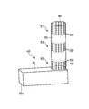
- FIG. 5 is a perspective view schematically showing an exhaust flue of the second embodiment.
- FIG. 6 is an explanatory diagram for explaining the positions of the porous regions of the second embodiment.
- FIG. 7 is a perspective view schematically showing an exhaust flue of the third embodiment.
- FIG. 8 is a partial cross-sectional view showing the AA cross section of FIG.
- FIG. 9 is a perspective view schematically showing an exhaust flue of the fourth embodiment.
- FIG. 10 is a cross-sectional view of the open end of the exhaust flue of the fifth embodiment.
- FIG. 11 is a cross-sectional view of the open end of the exhaust flue of the sixth embodiment.
- FIG. 12 is a cross-sectional view of the open end of the exhaust flue of the seventh embodiment.
- FIG. 13 is a cross-sectional view of the open end of the exhaust flue of the eighth embodiment.
- FIG. 14 is a cross-sectional view of the open end of the exhaust flue of the ninth embodiment.
- FIG. 15 is a perspective view schematically showing an exhaust flue of the tenth embodiment.
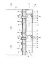
- FIG. 16 is a partial cross-sectional view showing a BB cross section of FIG.
- FIG. 1 is a schematic configuration diagram illustrating a gas turbine according to the first embodiment.
- the gas turbine includes a compressor 11, a combustor 12, and a turbine 13.
- a generator (not shown) is connected to the gas turbine and can generate power.
- the compressor 11 has an intake duct 20 for taking in air, an inlet guide vane (IGV) 22 is disposed in the compressor casing 21, and a plurality of stationary vanes 23 and moving blades 24 are arranged in the front-rear direction (described later). Are arranged alternately in the axial direction of the rotor 32, and the bleed chambers 25 are provided on the outside thereof.
- the combustor 12 is combustible by supplying fuel to the compressed air compressed by the compressor 11 and igniting it.
- a plurality of stationary blades 27 and moving blades 28 are alternately disposed in a turbine casing 26 in the front-rear direction (the axial direction of a rotor 32 described later).
- An exhaust chamber 30 is disposed downstream of the turbine casing 26 via an exhaust casing 29, and the exhaust chamber 30 has an exhaust diffuser 31 that is continuous with the turbine 13.
- the rotor (main shaft) 32 is positioned so as to penetrate through the center of the compressor 11, the combustor 12, the turbine 13, and the exhaust chamber 30.
- the end of the rotor 32 on the compressor 11 side is rotatably supported by the bearing portion 33, while the end of the exhaust chamber 30 side is rotatably supported by the bearing portion 34.
- a plurality of rotor disks 35 to which the rotor blades 24 are mounted are stacked and fixed in the compressor 11, and a plurality of rotor disks 36 to which the rotor blades 28 are mounted in the turbine 13.
- the driving shaft of the generator (not shown) is connected to the end on the exhaust chamber 30 side.
- the compressor casing 21 of the compressor 11 is supported by the legs 37
- the turbine casing 26 of the turbine 13 is supported by the legs 38
- the exhaust chamber 30 is supported by the legs 39.
- the air taken in from the intake duct 20 of the compressor 11 passes through the inlet guide vane 22, the plurality of stationary vanes 23, and the moving vanes 24 and is compressed to become high-temperature and high-pressure compressed air.
- a predetermined fuel is supplied to the compressed air in the combustor 12 and burned.
- the high-temperature and high-pressure combustion gas generated in the combustor 12 drives and rotates the rotor 32 by passing through the plurality of stationary blades 27 and the moving blades 28 constituting the turbine 13, and is connected to the rotor 32.
- a generator (not shown) is driven.
- the energy of the exhaust gas (combustion gas) is converted into pressure by the exhaust diffuser 31 in the exhaust chamber 30 and decelerated, and then sent to the exhaust flue described later.
- FIG. 2 is a perspective view schematically showing the exhaust flue of the first embodiment.
- FIG. 3 is a partial cross-sectional view schematically showing an open end porous region cut by a cross section passing through the center of the hole in FIG. 2.
- FIG. 4 is an explanatory diagram for explaining the sound pressure level of the low-frequency component radiated from the exhaust flue of the first embodiment.
- the exhaust flue 40 according to the first embodiment includes an exhaust duct main body 41 and an exhaust chimney main body 43.
- the exhaust duct body 41 has a predetermined length, a sheet metal is bent into a predetermined shape, and a connection port 30a that communicates with the exhaust chamber 30 described above is formed at one end, while the other end communicates.
- the exhaust chimney main body 43 communicates with the hole 42.
- the exhaust chimney main body 43 is formed of a cylindrical rolled metal. The exhaust gas in the exhaust chamber 30 is taken into the exhaust flue 40 through the connection port 30a and flows in the order of the exhaust duct main body 41, the communication hole 42, and the exhaust chimney main body 43. From the open end 44 of the exhaust chimney main body 43 to the atmosphere To be released.
- the pressure pulsation or the exhaust gas turbulence generated in the combustor 12 shown in FIG. 1 is amplified by the resonance vibration of the exhaust chimney 40, and the low frequency below the audible sound from the opening end 44 of the exhaust chimney main body 43.
- the sound of the component may be emitted.
- the sound of the low frequency component is several tens Hz or less (for example, about 1 Hz to 20 Hz).
- This low-frequency component sound is often a frequency component below human audible sound, so it is less likely to feel an abnormal noise directly, but it indirectly causes vibration (rattle) of the window frame of the house around the plant. May be a factor.
- the exhaust flue 40 includes an open end porous region 51 in which the exhaust chimney main body 43 has a plurality of holes 50 along the entire periphery of the open end 44.
- the construction of the open end porous region 51 requires only opening a plurality of holes 50 along the entire periphery of the open end 44 in the exhaust chimney main body 43, so that the construction period is short and the construction cost can be reduced.
- the sound of the low frequency component is amplified by the resonance vibration of the exhaust flue 40, and reflection of this resonance vibration occurs at the opening end 44.
- the hole 50 formed in the opening end 44 becomes an acoustic resistor, and the acoustic impedance at the opening end 44 increases.
- the amplification factor by which the pressure pulsation generated in the combustor 12 or the turbulent flow of the exhaust gas is amplified by the resonance vibration of the exhaust flue 40 is reduced, and the sound of the low frequency component radiated from the opening end 44 is suppressed.
- the hole 50 of the open end porous region 51 is such that the sound pressure level (SPL: Sound Pressure Level) [unit: dB] of the low frequency component emitted from the open end 44 is below the target value. Further, it is calculated as appropriate from the thickness t of the exhaust chimney main body 43, the diameter D of the holes 50, the interval P between the holes 50, and the number of holes 50 in the open end porous region 51.
- SPL Sound Pressure Level
- the sound pressure level curve 82 in the case where there is a hole 50 in the open end porous region 51 is shown in the exhaust chimney main body 43. It is calculated from the thickness t, the diameter D of the holes 50, the interval P between the holes 50, and the number of holes 50 in the open end porous region 51. And in the frequency component fg below the audible sound shown in FIG. 4, with respect to the sound pressure level curve L1 when there is no hole 50 of the open end porous region 51, the sound pressure when the hole 50 of the open end porous region 51 is present.
- the exhaust flue 40 according to the first embodiment is provided in the exhaust chimney main body 43 with the diameter D of the holes 50 shown in FIG. 3, the interval P between the holes 50, and the opening so that the SPL of the level curve L2 becomes the target value.
- the number of holes 50 in the end porous region 51 is set.
- the exhaust flue 40 includes the exhaust chimney main body 43 and the open end porous region 51.
- the exhaust chimney main body 43 is a passage for discharging exhaust gas.
- the open end porous region 51 is a region in which a plurality of holes 50 are formed along the entire periphery of the open end 44 of the exhaust chimney main body 43.
- FIG. 5 is a perspective view schematically showing an exhaust flue of the second embodiment.
- FIG. 6 is an explanatory diagram for explaining the positions of the porous regions of the second embodiment.
- the same components as those in the above-described embodiment are denoted by the same reference numerals, and redundant description is omitted.
- the exhaust chimney main body 43 includes an open end porous region 51, a second porous region 52, and a third porous region 53. Similar to the open end porous region 51, the second porous region 52 and the third porous region 53 are formed with a plurality of holes 50 along the periphery of the exhaust chimney main body 43. And between the open end porous region 51 and the third porous region 53, there is a region where the hole 50 is not opened. Further, there is a region where the hole 50 is not formed between the second porous region 52 and the third porous region 53.
- the exhaust flue 40 can ensure the strength of the exhaust chimney main body 43 because there is a region where the holes 50 are not opened.
- the position where the second porous region 52 and the third porous region 53 are provided in the exhaust chimney main body 43 is a position that becomes a node of each acoustic mode having a different sound of a low frequency component that resonates.
- L be the acoustic length of the exhaust flue 40.
- the acoustic length L is the length from the connection port 30a to the opening end 44.
- the acoustic length L is the length of the resonating space, and is appropriately set depending on the facility.
- the resonance frequency f of the exhaust flue 40 can be expressed by the following formula (1).
- c is the speed of sound waves (for example, 340 m / s). Since c is the product of the resonance frequency f and the wavelength ⁇ , it can be expressed by the following formula (2).
- the wavelength ⁇ can be obtained by the following equation (3) by substituting the resonance frequency f of the above equation (1) into the above equation (2).
- the exhaust flue 40 is provided with a second porous region 52 and a third porous region 53 at a position that becomes a node of a standing wave having a wavelength ⁇ that satisfies the formula (3).
- the position that becomes the node of the wavelength ⁇ of the primary component is the node N11 that is the same position as the opening end 44.
- the positions corresponding to the nodes of the wavelength ⁇ of the secondary component are the nodes N21 and N22 that are equal to the opening end 44.
- the positions that become the nodes of the wavelength ⁇ of the third-order component are the nodes N31, N32, and N33.
- the exhaust flue 40 includes the exhaust chimney main body 43 and the open end porous region 51.
- the exhaust flue 40 includes a second porous region 52 and a third porous region 53 which are other porous regions having a plurality of holes 50 at positions different from the open end porous region 51.
- the open end porous region 51 suppresses reflection of the acoustic mode of the primary component of resonance vibration in the exhaust chimney main body 43.
- the second porous region 52 suppresses the reflection of the acoustic mode of the secondary component of the resonance vibration in the exhaust chimney main body 43.
- the third porous region 53 suppresses reflection of the acoustic mode of the third-order component of resonance vibration in the exhaust chimney main body 43. Since the second porous region 52 and the third porous region 53 suppress reflection of resonance vibrations of higher-order acoustic modes, the resonance of the exhaust flue 40 compared to the exhaust flue 40 of the first embodiment. The amplification factor amplified by the vibration is reduced, and the low frequency component sound radiated from the opening end 44 is suppressed.
- the exhaust flue 40 can reduce the possibility of indirectly causing vibration (rattle) of a window frame of a house around the plant. Further, the exhaust flue 40 can be formed by a simple construction in which the second porous region 52 and the third porous region 53 open the hole 50 in the exhaust chimney main body 43.
- the exhaust chimney main body 43 includes the second porous region 52 and the third porous region 53, but may include only the second porous region 52 or the third porous region. Only the region 53 may be provided.
- n is 1 to 3 in the above formulas (1) to (3) is illustrated, but n may be 4 or more.
- FIG. 7 is a perspective view schematically showing an exhaust flue of the third embodiment.
- FIG. 8 is a partial cross-sectional view showing the AA cross section of FIG.
- the same components as those in the above-described embodiment are denoted by the same reference numerals, and redundant description is omitted.
- the exhaust flue 40 of Embodiment 3 includes an exhaust chimney main body 43 having an open end porous region 51 and an outer cylindrical portion 54 that covers the outer peripheral side of the open end porous region 51 with a gap 55 therebetween. As shown in FIG. 8, an air layer is formed in an annular shape in the gap 55 between the open end porous region 51 and the outer cylinder portion 54.
- the sound of the low frequency component is amplified by the resonance vibration of the exhaust flue 40, and reflection of this resonance vibration occurs at the opening end 44.
- the hole 50 formed in the opening end 44 becomes an acoustic resistor, and the acoustic impedance at the opening end 44 increases.
- the air gap 55 of the present embodiment restrains the movement of the acoustic particles at the outer cylinder portion 54, the acoustic impedance at the opening end 44 is increased.
- the amplification factor by which the pressure pulsation generated in the combustor 12 or the turbulent flow of the exhaust gas is amplified by the resonance vibration of the exhaust flue 40 is reduced, and the sound of the low frequency component radiated from the opening end 44 is suppressed.
- FIG. 9 is a perspective view schematically showing an exhaust flue of the fourth embodiment.
- the same components as those in the above-described embodiment are denoted by the same reference numerals, and redundant description is omitted.
- the exhaust flue 40 of the fourth embodiment is provided with reinforcing ribs 56 on the surface of the exhaust chimney main body 43 between the adjacent holes 50 in the open end porous region 51. .
- the strength of the exhaust chimney main body 43 tends to decrease as the number of holes 50 increases.
- the reinforcing rib 56 can maintain the strength of the exhaust chimney main body 43 at a certain level or more even if the hole 50 is provided.
- the reinforcing ribs 56 extend in the vertical direction of the exhaust chimney main body 43, and a plurality of reinforcing ribs 56 are arranged at predetermined intervals in the circumferential direction of the exhaust chimney main body 43. Is installed by welding.
- the reinforcing ribs 56 may be similarly provided in the second porous region 52 or the third porous region 53 as described above in the second embodiment.
- the exhaust chimney main body 43 includes the reinforcing rib 56 between the adjacent holes 50 in the open end porous region 51.
- the exhaust flue 40 of Embodiment 4 may be provided with the reinforcement rib 56 between the adjacent holes 50 in the 2nd porous area
- Reinforcing ribs 56 may be provided between adjacent holes 50 in the third porous region 53, which is a porous region.
- FIG. 10 is a cross-sectional view of the open end of the exhaust flue of the fifth embodiment.
- the same components as those in the above-described embodiment are denoted by the same reference numerals, and redundant description is omitted.
- the exhaust chimney main body 43 includes an outer wall portion 61 having a cylindrical shape, an inner wall portion 62 composed of a plurality of heat insulation panels, an outer wall portion 61 and an inner wall portion 62. And a heat insulating material 64 interposed between the outer wall portion 61 and the inner wall portion 62.
- the heat insulation panel constituting the inner wall portion 62 has a predetermined size and a curved shape corresponding to the outer wall portion 61, and has a cylindrical shape by overlapping and connecting the outer peripheral portions.
- One end portion of the connecting member 63 is fixed to the inner surface of the outer wall portion 61 by welding, the other end portion passes through an overlapping portion of the plurality of heat insulation panels, and a nut 63a is screwed. Therefore, the inner wall 62 is configured by connecting a plurality of heat insulation panels, and the inner wall 62 is connected to the outer wall 61.
- the exhaust chimney main body 43 is provided with an open end porous region 51 on the open end 44 side.
- a through hole 65 penetrating the outer wall portion 61, the heat insulating material 64 and the inner wall portion 62 is formed.
- the cylindrical member 66 is integrally formed with a flange portion 66b at the base end portion of the cylindrical portion 66a, and is fitted into the through hole 65 from the inside of the exhaust chimney main body 43.
- the cylindrical member 66 has a flange portion 66b fixed to the inner wall portion 62 by welding, and can absorb a difference in thermal extension from the exhaust chimney main body 43 by making the tip portion free. Therefore, the inside of the cylindrical member 66 functions as the hole 50 in the open end porous region 51.
- the tip of the cylindrical member 66 and the outer wall 61 may be fixed by welding.
- the exhaust flue 40 of the fifth embodiment is interposed between the outer wall portion and the inner wall portion, and the connecting member 63 that connects the exhaust chimney main body 43 to both the outer wall portion 61 and the inner wall portion 62.
- the hole 50 is formed through the outer wall portion 61, the heat insulating material 64 and the inner wall portion 62.
- the exhaust flue 40 of the fifth embodiment configures the hole 50 by allowing the cylindrical member 66 to penetrate the inner wall portion 62, the heat insulating material 64, and the outer wall portion 61.
- the exhaust flue 40 can easily form the hole 50 using the cylindrical member 66, and the structure can be simplified.
- the intrusion of exhaust gas between the inner wall portion 62 and the outer wall portion 61 can be suppressed by the cylindrical member 66.
- by fixing the flange portion 66b of the cylindrical member 66 to the inner wall portion 62 by welding an exhaust gas seal is formed, and intrusion of exhaust gas into the interior can be surely prevented. As a result, durability can be improved.
- FIG. 11 is a cross-sectional view of the open end of the exhaust flue of the sixth embodiment.
- the same components as those in the above-described embodiment are denoted by the same reference numerals, and redundant description is omitted.
- the exhaust flue 40 of Embodiment 6 is provided with an outer cylinder portion 72 that covers the outer peripheral side of the open end porous region 51 with a gap 71 therebetween.
- the air gap 71 is provided between the outside of the open end porous region 51 of the exhaust chimney main body 43 and the inside of the outer cylindrical portion 72, and is an annular air layer that opens downward and upward.
- the outer cylinder part 72 is set to have a larger diameter than the exhaust chimney main body 43 (open end porous region 51), and is supported by the exhaust chimney main body 43 by a plurality of support members 73.
- One end of the support member 73 is fixed to the outer surface of the exhaust chimney main body 43 (open end porous region 51) by welding, the bent portion 73a at the other end contacts the inner surface of the outer cylindrical portion 72, and the bolt 74 and Fastened with a nut 75.
- the outer cylinder portion 72 is provided by opening the gap 71 on the outer peripheral side of the open end porous region 51 in the exhaust chimney main body 43, and the lower end and the upper end of the gap 71 are connected to the outside. Is open.
- the exhaust gas discharged into the gap 71 through each hole 50 of the open end porous region 51 is mixed with the outside air entering from the lower end of the gap 71 and cooled. Thereafter, the exhaust gas after cooling rises through the gap 71 and is discharged from the upper end, so that the high temperature of the outer wall portion 61 can be suppressed.
- the open end porous region 51 (each hole 50) is covered from the outside by the outer cylindrical portion 72, and the appearance quality can be improved.
- FIG. 12 is a cross-sectional view of the open end of the exhaust flue of the seventh embodiment.
- the same components as those in the above-described embodiment are denoted by the same reference numerals, and redundant description is omitted.
- the exhaust flue 40 of the seventh embodiment is provided with an outer cylinder portion 72 that covers the outer peripheral side of the open end porous region 51 with a gap 71 therebetween.
- the outer cylinder portion 72 is provided with a heat insulating material 76 on the inner surface facing the hole 50.
- the outer cylinder portion 72 is provided on the outer peripheral side of the open end porous region 51 in the exhaust chimney main body 43, and the heat insulating material is provided on the inner surface facing the hole 50. 76 is provided.
- FIG. 13 is a cross-sectional view of the open end of the exhaust flue of the eighth embodiment.
- the same components as those in the above-described embodiment are denoted by the same reference numerals, and redundant description is omitted.
- the exhaust flue 40 of the eighth embodiment is provided with an outer cylinder portion 72 that covers the outer peripheral side of the open end porous region 51 with a gap 71 therebetween. And this outer cylinder part 72 is provided with the rib 77 in the outer surface.
- the ribs 77 are fixed orthogonally to the outer surface of the outer cylindrical portion 72, and a plurality of ribs 77 are arranged at equal intervals in the circumferential direction.
- the rib 77 is divided
- the rib 77 is being fixed to the outer surface of the outer cylinder part 72 along the up-down direction, you may fix along the circumferential direction and may arrange two or more at equal intervals in the up-down direction.
- the outer cylinder part 72 is provided by opening the gap 71 on the outer peripheral side of the open end porous region 51 in the exhaust chimney main body 43, and the rib 77 on the outer surface of the outer cylinder part 72. Is provided. With this structure, the acoustic impedance at the opening end 44 can be optimized by making the dimensions and shape of the ribs 77 different.
- FIG. 14 is a cross-sectional view of the open end of the exhaust flue of the ninth embodiment.
- the same components as those in the above-described embodiment are denoted by the same reference numerals, and redundant description is omitted.
- the exhaust flue 40 of the ninth embodiment is configured by connecting a plurality of porous structure blocks 40A, 40B, 40C having a cylindrical shape with a predetermined length.
- Each porous structure block 40A, 40B, 40C includes an outer wall portion 61 having a cylindrical shape, an inner wall portion 62 composed of a plurality of heat insulation panels, a plurality of connecting members 63 that connect the outer wall portion 61 and the inner wall portion 62, and an outer wall.
- a heat insulating material 64 interposed between the inner wall portion and the inner wall portion, and a lid member 67 for preventing the heat insulating material 64 from falling off at the upper and lower end portions of the outer wall portion 61 and the inner wall portion 62.
- each porous structure block 40A, 40B, 40C contacts each cover member 67, and the inner peripheral surface and the outer peripheral surface are connected by welding.
- each of the porous structure blocks 40A, 40B, 40C is provided with outer cylinder portions 81, 82, 83 that cover the outer peripheral side with a gap 71 therebetween.
- the outer cylindrical portions 81 and 82 are formed such that large diameter portions 81a and 82a are formed at the lower end portions and overlap with the upper end portions of the outer cylindrical portions 82 and 83.
- the outer cylinder portions 81, 82, 83 are supported by a support member 73.
- the exhaust flue 40 of the ninth embodiment is configured by connecting a plurality of porous structure blocks 40A, 40B, 40C having a cylindrical shape with a predetermined length.
- a plurality of porous structure blocks 40A, 40B, and 40C are manufactured at a factory, and the plurality of porous structure blocks 40A, 40B, and 40C are transported to the site, and the plurality of porous structure blocks 40A, 40B, and 40C are The exhaust flue is connected to make it possible to simplify the manufacturing process and reduce the construction cost.
- the exhaust flue 40 By configuring the exhaust flue 40 with a plurality of porous structure blocks 40A, 40B, 40C, for example, by changing the position and size of the opening portions of the outer cylinder portions 81, 82, 83, the opening end 44
- the acoustic impedance can be optimized.
- FIG. 15 is a perspective view schematically showing the exhaust flue of the tenth embodiment
- FIG. 16 is a partial cross-sectional view showing a BB cross section of FIG.
- the exhaust flue 40 of the tenth embodiment includes an open end porous region 51 in which the exhaust chimney main body 43 has a plurality of holes 50 at least partially around the entire periphery of the open end 44. ing. Specifically, the open end porous region 51 is provided on the open end 44 side inside the bending direction of the exhaust chimney main body 43.
- the exhaust flue 40 is bent at a substantially right angle from the exhaust duct main body 41 and connected to the exhaust chimney main body 43, and an open end porous region 51 is provided in a part of the open end 44. Since the exhaust gas is bent at a substantially right angle from the exhaust duct main body 41 and flows through the exhaust chimney main body 43, a hole 50 is formed on the opening end 44a side inside the bending direction of the exhaust chimney main body 43, and on the opening end 44b side. The hole 50 is not formed. For example, the hole 50 is formed in the angle region of ⁇ 1 on the opening end 44a side of the opening end porous region 51 in the exhaust chimney main body 43, and the hole 50 is not formed in the angle region of ⁇ 2 on the opening end 44b side.
- the exhaust chimney main body 43 has an opening end on at least a part of the entire periphery of the opening end 44, for example, on the opening end 44 side inside the bending direction of the exhaust chimney main body 43.
- a porous region 51 is provided. With this structure, exhaust gas discharged from the open end porous region 51 can be reduced.
- the open end porous region 51 is provided on the inner side in the bending direction of the exhaust chimney main body 43.
- the opening end porous region 51 is not limited to this position, and may be appropriately set according to the shape of the exhaust flue 40. It is good.
- the exhaust flue according to each embodiment described above is applied to a gas turbine.
- the present invention is not limited to a gas turbine, and any facility that discharges exhaust gas can be applied. .
Landscapes
- Engineering & Computer Science (AREA)
- Chemical & Material Sciences (AREA)
- Combustion & Propulsion (AREA)
- Mechanical Engineering (AREA)
- General Engineering & Computer Science (AREA)
- Chimneys And Flues (AREA)
- Exhaust Silencers (AREA)
- Structures Of Non-Positive Displacement Pumps (AREA)
Abstract
Priority Applications (4)
| Application Number | Priority Date | Filing Date | Title |
|---|---|---|---|
| US14/768,868 US9970358B2 (en) | 2012-03-14 | 2013-09-09 | Exhaust flue |
| CN201380073956.8A CN105008695B (zh) | 2012-03-14 | 2013-09-09 | 排气烟道 |
| DE112013006822.2T DE112013006822T5 (de) | 2012-03-14 | 2013-09-09 | Abgaszug |
| KR1020157023213A KR101707363B1 (ko) | 2012-03-14 | 2013-09-09 | 배기 연도 |
Applications Claiming Priority (3)
| Application Number | Priority Date | Filing Date | Title |
|---|---|---|---|
| JP2012057809 | 2012-03-14 | ||
| JP2013-049576 | 2013-03-12 | ||
| JP2013049576A JP6071664B2 (ja) | 2012-03-14 | 2013-03-12 | 排気煙道 |
Publications (1)
| Publication Number | Publication Date |
|---|---|
| WO2014141509A1 true WO2014141509A1 (fr) | 2014-09-18 |
Family
ID=49589725
Family Applications (1)
| Application Number | Title | Priority Date | Filing Date |
|---|---|---|---|
| PCT/JP2013/074262 Ceased WO2014141509A1 (fr) | 2012-03-14 | 2013-09-09 | Conduite d'échappement |
Country Status (6)
| Country | Link |
|---|---|
| US (1) | US9970358B2 (fr) |
| JP (1) | JP6071664B2 (fr) |
| KR (1) | KR101707363B1 (fr) |
| CN (1) | CN105008695B (fr) |
| DE (1) | DE112013006822T5 (fr) |
| WO (1) | WO2014141509A1 (fr) |
Families Citing this family (7)
| Publication number | Priority date | Publication date | Assignee | Title |
|---|---|---|---|---|
| JP5578384B1 (ja) * | 2013-11-15 | 2014-08-27 | 株式会社東洋新薬 | N−アセチルグルコサミンを含む風味改善方法及び風味改善用組成物 |
| JP6302238B2 (ja) * | 2013-12-20 | 2018-03-28 | 三菱重工業株式会社 | 排気装置及びガスタービン |
| JP6618780B2 (ja) * | 2015-11-13 | 2019-12-11 | 三菱日立パワーシステムズ株式会社 | 煙突騒音低減装置 |
| JP6649119B2 (ja) * | 2016-02-26 | 2020-02-19 | 三菱重工業株式会社 | 排気ガス消音器、ガスタービン設備、及び原子力プラント |
| CN106121189A (zh) * | 2016-06-24 | 2016-11-16 | 陈桂霞 | 一种排气烟道 |
| WO2020051623A1 (fr) | 2018-09-13 | 2020-03-19 | The University Of Adelaide | Ensemble pour gaz d'échappement |
| US20250250922A1 (en) * | 2024-02-01 | 2025-08-07 | Solar Turbines Incorporated | Sound-attenuating devices |
Citations (12)
| Publication number | Priority date | Publication date | Assignee | Title |
|---|---|---|---|---|
| JPS62132722U (fr) * | 1986-02-17 | 1987-08-21 | ||
| JPH043240U (fr) * | 1990-04-13 | 1992-01-13 | ||
| JPH05321482A (ja) * | 1992-05-19 | 1993-12-07 | Ohbayashi Corp | 既存鋼製煙突の補強方法 |
| JPH10205169A (ja) * | 1997-01-21 | 1998-08-04 | Mitsubishi Heavy Ind Ltd | 煙突筒身の建付け方法及び煙突筒身ブロック |
| JPH10325533A (ja) * | 1997-05-28 | 1998-12-08 | Babcock Hitachi Kk | ダクトの補強構造 |
| JPH11159347A (ja) * | 1997-09-25 | 1999-06-15 | Mitsubishi Heavy Ind Ltd | ガスタービン排気煙道 |
| JP2000314512A (ja) * | 2000-01-01 | 2000-11-14 | Koichi Horie | 蓄糞等の燃焼装置及び燃焼方法 |
| JP2001090522A (ja) * | 1999-09-21 | 2001-04-03 | Kubota Corp | エンジン |
| JP2003120025A (ja) * | 2001-10-11 | 2003-04-23 | Chikara Miyamoto | プラスチック製多孔型枠 |
| JP2004094065A (ja) * | 2002-09-03 | 2004-03-25 | Kawasaki Heavy Ind Ltd | 騒音低減装置および排気装置 |
| JP2009198092A (ja) * | 2008-02-21 | 2009-09-03 | Mitsubishi Heavy Ind Ltd | グランドフレア |
| JP2010127246A (ja) * | 2008-11-28 | 2010-06-10 | Mitsubishi Heavy Ind Ltd | 排気ダクト |
Family Cites Families (27)
| Publication number | Priority date | Publication date | Assignee | Title |
|---|---|---|---|---|
| US2869671A (en) * | 1953-08-31 | 1959-01-20 | Karl E Schlachter | Gas turbine muffler |
| US3187835A (en) * | 1960-02-08 | 1965-06-08 | Cloyd D Smith | Jet engine noise suppressor |
| US3196977A (en) * | 1960-04-27 | 1965-07-27 | Industrial Acoustics Co | Sound attenuation control means including diffuser for high velocity streams |
| US3159238A (en) * | 1960-12-01 | 1964-12-01 | Curtiss Wright Corp | Diffuser screen with heat-insulating rungs for exhaust noise suppressor for reactionengines |
| US3688865A (en) * | 1970-11-17 | 1972-09-05 | Cloyd D Smith | Jet engine noise suppressor |
| JPS5121409Y2 (fr) * | 1973-01-19 | 1976-06-03 | ||
| JPS5249004Y2 (fr) * | 1973-12-03 | 1977-11-08 | ||
| US3894610A (en) * | 1974-08-20 | 1975-07-15 | Burgess Ind | Gas stream silencer |
| US4180141A (en) | 1975-11-24 | 1979-12-25 | Judd Frederick V H | Distributor for gas turbine silencers |
| FR2589195B1 (fr) * | 1985-10-25 | 1989-07-28 | Vibrasonic | Cheminee insonorisee pour gaz chauds ejectes d'un tube d'echappement |
| JPS62132722A (ja) | 1985-12-02 | 1987-06-16 | Ise Kagaku Kogyo Kk | 脱鉄精製法 |
| JPH01273909A (ja) * | 1988-04-27 | 1989-11-01 | Matsushita Electric Ind Co Ltd | 燃焼排気装置 |
| CA1277604C (fr) * | 1988-09-30 | 1990-12-11 | Heinz H. Rieger | Dispositif reducteur de bruit ambiant sur cheminee de foyer a feu nu |
| JP2818265B2 (ja) | 1989-06-28 | 1998-10-30 | アウシモント、ソチエタ、ア、レスポンサビリタ、リミタータ | ブロモジフルオロアセチルフルオリドの製造方法 |
| JPH0338543U (fr) * | 1989-08-02 | 1991-04-15 | ||
| JPH043240A (ja) | 1990-04-20 | 1992-01-08 | Hitachi Zosen Corp | ニューラルネット学習方法 |
| JP3325991B2 (ja) | 1994-01-31 | 2002-09-17 | 株式会社東芝 | 排気サイレンサ |
| JPH087232A (ja) | 1994-06-23 | 1996-01-12 | Murata Mfg Co Ltd | 磁気センサ装置 |
| US5837890A (en) * | 1994-12-12 | 1998-11-17 | Aero Systems Engineering, Inc. | Jet engine test cell structure |
| JPH09112244A (ja) | 1995-10-23 | 1997-04-28 | Hitachi Ltd | 消音装置 |
| US5960787A (en) * | 1997-05-06 | 1999-10-05 | Teledyne Industries, Inc. | Gas appliance combustion systems |
| US6161646A (en) * | 1999-08-17 | 2000-12-19 | Eaton Aeroquip Inc. | Turbo-generator exhaust noise silencer |
| WO2003023281A1 (fr) | 2001-09-07 | 2003-03-20 | Alstom Technology Ltd | Ensemble amortisseur concu pour reduire les pulsations d'une chambre de combustion dans une installation de turbine a gaz |
| US7707818B2 (en) * | 2008-02-11 | 2010-05-04 | General Electric Company | Exhaust stacks and power generation systems for increasing gas turbine power output |
| US8240427B2 (en) * | 2008-10-01 | 2012-08-14 | General Electric Company | Sound attenuation systems and methods |
| JP5404031B2 (ja) * | 2008-12-26 | 2014-01-29 | 三菱重工業株式会社 | グランドフレア |
| CN102518499A (zh) | 2011-11-29 | 2012-06-27 | 中国商用飞机有限责任公司 | 一种消音器 |
-
2013
- 2013-03-12 JP JP2013049576A patent/JP6071664B2/ja not_active Expired - Fee Related
- 2013-09-09 DE DE112013006822.2T patent/DE112013006822T5/de not_active Withdrawn
- 2013-09-09 WO PCT/JP2013/074262 patent/WO2014141509A1/fr not_active Ceased
- 2013-09-09 KR KR1020157023213A patent/KR101707363B1/ko not_active Expired - Fee Related
- 2013-09-09 CN CN201380073956.8A patent/CN105008695B/zh not_active Expired - Fee Related
- 2013-09-09 US US14/768,868 patent/US9970358B2/en not_active Expired - Fee Related
Patent Citations (12)
| Publication number | Priority date | Publication date | Assignee | Title |
|---|---|---|---|---|
| JPS62132722U (fr) * | 1986-02-17 | 1987-08-21 | ||
| JPH043240U (fr) * | 1990-04-13 | 1992-01-13 | ||
| JPH05321482A (ja) * | 1992-05-19 | 1993-12-07 | Ohbayashi Corp | 既存鋼製煙突の補強方法 |
| JPH10205169A (ja) * | 1997-01-21 | 1998-08-04 | Mitsubishi Heavy Ind Ltd | 煙突筒身の建付け方法及び煙突筒身ブロック |
| JPH10325533A (ja) * | 1997-05-28 | 1998-12-08 | Babcock Hitachi Kk | ダクトの補強構造 |
| JPH11159347A (ja) * | 1997-09-25 | 1999-06-15 | Mitsubishi Heavy Ind Ltd | ガスタービン排気煙道 |
| JP2001090522A (ja) * | 1999-09-21 | 2001-04-03 | Kubota Corp | エンジン |
| JP2000314512A (ja) * | 2000-01-01 | 2000-11-14 | Koichi Horie | 蓄糞等の燃焼装置及び燃焼方法 |
| JP2003120025A (ja) * | 2001-10-11 | 2003-04-23 | Chikara Miyamoto | プラスチック製多孔型枠 |
| JP2004094065A (ja) * | 2002-09-03 | 2004-03-25 | Kawasaki Heavy Ind Ltd | 騒音低減装置および排気装置 |
| JP2009198092A (ja) * | 2008-02-21 | 2009-09-03 | Mitsubishi Heavy Ind Ltd | グランドフレア |
| JP2010127246A (ja) * | 2008-11-28 | 2010-06-10 | Mitsubishi Heavy Ind Ltd | 排気ダクト |
Also Published As
| Publication number | Publication date |
|---|---|
| DE112013006822T5 (de) | 2015-12-10 |
| KR20150111997A (ko) | 2015-10-06 |
| US9970358B2 (en) | 2018-05-15 |
| JP6071664B2 (ja) | 2017-02-01 |
| KR101707363B1 (ko) | 2017-02-15 |
| JP2013217369A (ja) | 2013-10-24 |
| US20150377139A1 (en) | 2015-12-31 |
| CN105008695A (zh) | 2015-10-28 |
| CN105008695B (zh) | 2018-02-16 |
Similar Documents
| Publication | Publication Date | Title |
|---|---|---|
| JP6071664B2 (ja) | 排気煙道 | |
| KR101723323B1 (ko) | 가스 터빈용 소음기 및 이 소음기를 구비한 가스 터빈 | |
| JP4942594B2 (ja) | ヘリコプター用ガスタービンエンジンの消音のための装置、およびそのようにして得られるエンジン | |
| EP2402658B1 (fr) | Chambre de combustion et turbine à gaz équipée de ladite chambre de combustion | |
| US8733496B2 (en) | Acoustic damper, combustor, and gas turbine | |
| CN108626747B (zh) | 燃烧器声阻尼结构 | |
| US20130306403A1 (en) | Method for the production of a sound absorber, especially for a gas turbine exhaust cone | |
| CN107250491B (zh) | 衰减装置、燃烧器以及燃气轮机 | |
| RU2451193C2 (ru) | Вертолетный газотурбинный двигатель с уровнем шума, понижаемым с помощью шумоглушительного оборудования для эжектора | |
| JP2019526028A (ja) | 共振器リングを備えるガスタービンエンジン | |
| JP2009197623A (ja) | 遠心送風機 | |
| US9371778B2 (en) | Engine casing of an aircraft gas turbine having sound-absorbing elements in the fan inflow region | |
| JP5972619B2 (ja) | 吸気ダクト | |
| JP2019143494A (ja) | 軸流送風機及びボイラシステム並びに軸流送風機の製造方法 | |
| JP6640581B2 (ja) | 音響ダンパ、燃焼器およびガスタービン | |
| JP3999646B2 (ja) | ガスタービン燃焼器、及びこれを備えたガスタービン | |
| JP6104657B2 (ja) | 排気装置 | |
| JP6302238B2 (ja) | 排気装置及びガスタービン | |
| JP2008064405A (ja) | ガスタービン燃焼器 | |
| JPH07189999A (ja) | 軸流ファン | |
| JP2015140747A (ja) | 消音器及び過給機 |
Legal Events
| Date | Code | Title | Description |
|---|---|---|---|
| 121 | Ep: the epo has been informed by wipo that ep was designated in this application |
Ref document number: 13878183 Country of ref document: EP Kind code of ref document: A1 |
|
| WWE | Wipo information: entry into national phase |
Ref document number: 14768868 Country of ref document: US |
|
| ENP | Entry into the national phase |
Ref document number: 20157023213 Country of ref document: KR Kind code of ref document: A |
|
| WWE | Wipo information: entry into national phase |
Ref document number: 1120130068222 Country of ref document: DE Ref document number: 112013006822 Country of ref document: DE |
|
| 122 | Ep: pct application non-entry in european phase |
Ref document number: 13878183 Country of ref document: EP Kind code of ref document: A1 |