WO2015019456A1 - Appareil de détection de position de fil et machine d'insertion de composant - Google Patents
Appareil de détection de position de fil et machine d'insertion de composant Download PDFInfo
- Publication number
- WO2015019456A1 WO2015019456A1 PCT/JP2013/071436 JP2013071436W WO2015019456A1 WO 2015019456 A1 WO2015019456 A1 WO 2015019456A1 JP 2013071436 W JP2013071436 W JP 2013071436W WO 2015019456 A1 WO2015019456 A1 WO 2015019456A1
- Authority
- WO
- WIPO (PCT)
- Prior art keywords
- lead
- component
- pair
- lead position
- gripping
- Prior art date
- Legal status (The legal status is an assumption and is not a legal conclusion. Google has not performed a legal analysis and makes no representation as to the accuracy of the status listed.)
- Ceased
Links
Images





Classifications
-
- H—ELECTRICITY
- H05—ELECTRIC TECHNIQUES NOT OTHERWISE PROVIDED FOR
- H05K—PRINTED CIRCUITS; CASINGS OR CONSTRUCTIONAL DETAILS OF ELECTRIC APPARATUS; MANUFACTURE OF ASSEMBLAGES OF ELECTRICAL COMPONENTS
- H05K13/00—Apparatus or processes specially adapted for manufacturing or adjusting assemblages of electric components
- H05K13/08—Monitoring manufacture of assemblages
-
- H—ELECTRICITY
- H05—ELECTRIC TECHNIQUES NOT OTHERWISE PROVIDED FOR
- H05K—PRINTED CIRCUITS; CASINGS OR CONSTRUCTIONAL DETAILS OF ELECTRIC APPARATUS; MANUFACTURE OF ASSEMBLAGES OF ELECTRICAL COMPONENTS
- H05K13/00—Apparatus or processes specially adapted for manufacturing or adjusting assemblages of electric components
- H05K13/04—Mounting of components, e.g. of leadless components
- H05K13/0404—Pick-and-place heads or apparatus, e.g. with jaws
-
- H—ELECTRICITY
- H05—ELECTRIC TECHNIQUES NOT OTHERWISE PROVIDED FOR
- H05K—PRINTED CIRCUITS; CASINGS OR CONSTRUCTIONAL DETAILS OF ELECTRIC APPARATUS; MANUFACTURE OF ASSEMBLAGES OF ELECTRICAL COMPONENTS
- H05K13/00—Apparatus or processes specially adapted for manufacturing or adjusting assemblages of electric components
- H05K13/04—Mounting of components, e.g. of leadless components
- H05K13/0417—Feeding with belts or tapes
- H05K13/0421—Feeding with belts or tapes with treatment of the terminal leads
-
- H—ELECTRICITY
- H05—ELECTRIC TECHNIQUES NOT OTHERWISE PROVIDED FOR
- H05K—PRINTED CIRCUITS; CASINGS OR CONSTRUCTIONAL DETAILS OF ELECTRIC APPARATUS; MANUFACTURE OF ASSEMBLAGES OF ELECTRICAL COMPONENTS
- H05K13/00—Apparatus or processes specially adapted for manufacturing or adjusting assemblages of electric components
- H05K13/08—Monitoring manufacture of assemblages
- H05K13/081—Integration of optical monitoring devices in assembly lines; Processes using optical monitoring devices specially adapted for controlling devices or machines in assembly lines
- H05K13/0812—Integration of optical monitoring devices in assembly lines; Processes using optical monitoring devices specially adapted for controlling devices or machines in assembly lines the monitoring devices being integrated in the mounting machine, e.g. for monitoring components, leads, component placement
-
- H—ELECTRICITY
- H05—ELECTRIC TECHNIQUES NOT OTHERWISE PROVIDED FOR
- H05K—PRINTED CIRCUITS; CASINGS OR CONSTRUCTIONAL DETAILS OF ELECTRIC APPARATUS; MANUFACTURE OF ASSEMBLAGES OF ELECTRICAL COMPONENTS
- H05K13/00—Apparatus or processes specially adapted for manufacturing or adjusting assemblages of electric components
- H05K13/08—Monitoring manufacture of assemblages
- H05K13/081—Integration of optical monitoring devices in assembly lines; Processes using optical monitoring devices specially adapted for controlling devices or machines in assembly lines
- H05K13/0813—Controlling of single components prior to mounting, e.g. orientation, component geometry
Definitions
- the present invention relates to a technique for detecting a lead position of an insertion component when the insertion component is gripped and inserted and mounted on an electronic board.
- Patent Document 1 there is a technique in which a lead of an insertion part is automatically inserted into an insertion hole of an electronic board and the insertion part is inserted and mounted on the electronic board.
- Japanese Patent Laid-Open No. 2004-133867 images the insertion part with an imaging device while gripping the main body of the insertion part, detects the tip position of the lead from the image of the insertion part, and detects the relative position of the lead and the insertion hole.
- Patent Literature 1 since the main body portion of the insertion component is gripped, when the gripped insertion component is tilted, the image captured by the imaging device includes not only the tip of the lead, The lead surface is also shown. The image picked up by the image pickup device also shows the metal surface of the main body from which the lead protrudes. For this reason, there are cases in which the lead tip cannot be distinguished from other portions, and the lead tip position cannot be detected accurately. For this reason, due to inaccurate detection of the relative position between the lead and the insertion hole, the lead could not be inserted into the insertion hole, resulting in an insertion error.
- the present invention has been made in view of such circumstances, and an object of the present invention is to provide a technique capable of detecting a lead position when an insertion component is mounted on an electronic board.
- the invention according to claim 1, which has been made to solve the above-described problem, is a main body, a gripping device that grips a lead of an insertion part with a pair of clamp members, and attached to the main body to move the gripping device.
- a moving device an imaging device that images the lead held by the pair of clamp members; and a lead position detection unit that detects a lead position from an image including the lead imaged by the imaging device.
- the lead is imaged while the lead is gripped by the clamp member and the lead position is detected, it is possible to suppress the inclination of the insertion part during imaging, and to insert a part other than the tip of the lead Since the component is hidden by the clamp member, the lead and other portions can be distinguished, and the lead position can be detected reliably.
- the invention according to claim 2 made to solve the above-described problem is a component insertion machine for inserting a lead of an insertion component into an insertion hole of an electronic board and mounting the insertion part on the electronic board.
- a main body a gripping device for gripping the lead of the insertion part supplied to the component supply unit with a pair of clamp members, a moving device attached to the main body and moving the gripping device, and the pair of clamp members
- An image pickup device for picking up an image of the lead held by the image pickup device, a lead position detection unit for detecting a lead position from an image including the lead picked up by the image pickup device, and the lead position detected by the lead position detection unit. Based on this, the control unit that moves the gripping device by the moving device and inserts the lead gripped by the pair of clamp members into the insertion hole; A.
- the lead is imaged in a state where the lead is gripped by the clamp member and the lead position is detected, the inclination of the insertion part at the time of imaging can be suppressed, and the insertion of the part other than the tip of the lead Since the component is hidden by the clamp member, the lead and other portions can be distinguished, and the lead position can be detected reliably. Further, since the gripping device is moved by the moving device based on the lead position, the lead can be surely inserted into the insertion hole, and the insertion component can be reliably inserted and mounted on the electronic board.
- At least one of the pair of clamp members includes a lead position restriction that restricts a position of the lead with respect to the clamp member when the lead is gripped.
- the part is formed.
- the lead position storage unit stores the lead position detected by the lead position detection unit, and the lead position is detected by the lead position detection unit.
- the control unit moves the gripping device by the moving device based on the lead position stored in the lead position storage unit, and is gripped by the gripping device. The lead is inserted into the insertion hole.
- the lead is inserted into the insertion hole based on the lead position stored in the lead position storage unit.
- the lead is corrected by the lead position restricting portion. For this reason, once the lead position is detected, even if the lead position is not detected each time, the lead of the inserted component supplied to the component supply unit is corrected to the detected lead position, and the lead is securely inserted into the insertion hole. Can be inserted. In this way, since it is not necessary to detect the lead position for each insertion and mounting of the insertion component, the tact time for inserting the lead into the insertion hole can be shortened, and the productivity of the insertion mounting is improved.
- the lead position restricting portion is a V-groove formed on at least one opposing surface of the clamp member.
- the invention according to claim 6 is the invention according to any one of claims 2 to 5, wherein the lead extends when the insertion component side gripped by the pair of clamp members is viewed from the imaging device.
- the gripping device is configured such that the base of the insertion part is hidden by the clamp member.
- the pair of clamp members have a light / dark difference with respect to the lead. Therefore, a pair of clamp member and a lead can be identified reliably, a lead can be recognized reliably, and a lead position can be detected reliably.
- FIG. 6 is a detailed view showing a state in which a pair of clamp parts is opened, and is a view as viewed in FIG. It is detail drawing of a state where a pair of clamp parts were closed. It is a flowchart of an insertion mounting process. It is the figure which showed the lead containing image. It is explanatory drawing which showed the state which is inserting and mounting an insertion component in an electronic substrate with a holding
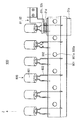
- the component insertion machine 100 includes a substrate transport device 10, a plurality of tape feeders 21, a component insertion unit 40, a lead imaging device 60, and a control unit 50.
- the substrate transport direction is the X-axis direction. In the horizontal plane, the direction orthogonal to the X-axis direction is taken as the Y-axis direction. A vertical direction orthogonal to the X-axis direction and the Y-axis direction is taken as a Z-axis direction.
- a plurality of slots 22 are juxtaposed in the X-axis direction at the front of the component insertion machine 100.
- Each tape feeder 21 is detachably attached to each slot 22.
- Each tape feeder 21 is detachably attached with a carrier tape storage portion 23 opened upward.
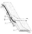
- the carrier tape storage unit 23 stores the carrier tape 900 shown in FIG. 2 in a folded state.
- the carrier tape 900 holds the insertion parts 800 in a row.
- the insertion part 800 has a lead 802.
- the lead 802 is inserted into an insertion hole 700a (shown in FIG. 10) of the electronic substrate 700 (hereinafter simply referred to as the substrate 700) and is electrically connected to an electric circuit formed on the substrate 700.
- the insertion part 800 includes a radial part such as a capacitor in which a plurality of leads 802 extend in the same direction and in parallel from one end of the main body 801, and a pair of leads from both ends of the main body.
- Axial parts (not shown) such as resistors are included.
- the carrier tape 900 is composed of a mount tape 901 and an adhesive tape 902.
- the adhesive tape 902 is affixed to the mount tape 901, and the lead 802 of the insert component 800 is sandwiched between the mount tape 901 and the insert component 800 is held on the mount tape 901.
- the mount tape 901 and the adhesive tape 902 are formed with engagement holes 901a and 902a at regular intervals in the longitudinal direction of these tapes.
- the tape feeder 21 has sprockets (not shown) that engage with the engagement holes 901a and 902a.
- the sprocket is driven by a sprocket servomotor (not shown), feeds the carrier tape 900 at every pitch between adjacent engagement holes 901a and 902a, and inserts the parts held by the carrier tape 900 into the tape feeder 21.
- a sprocket servomotor not shown
- the tape feeder 21 includes a guide 21b that changes the orientation of the carrier tape 900 so that the lead 802 of the insertion component 800 supplied to the component supply unit 21a faces the Z-axis direction.
- the tape feeder 21 includes a cutter 21 d that cuts the leads 802.
- the cutter 21d is driven by a cutter actuator.
- the tape feeder 21 is provided with a lead cutting device (not shown) for holding the lead 802 when the lead 802 is cut by the cutter 21d.
- the board transfer device 10 has a conveyor (not shown) for sequentially transferring the board 700 to the component insertion machine 100 on the downstream side in the X-axis direction, and a clamp for positioning and fixing at the mounting position in the transferred part insertion machine 100. is doing.
- two substrate transfer apparatuses 10 are arranged in parallel in the Y-axis direction on the base 41 of the component insertion unit 40.
- the component insertion unit 40 includes a guide rail 42, a Y-axis slide 43, a Y-axis servo motor 44, an X-axis slide 45, an X-axis servo motor (not shown), and a gripping device 70. .
- the Y-robot is composed of the guide rail 42, the Y-axis slide 43, and the Y-axis servo motor 44.
- the guide rail 42 is mounted and mounted on the base 41 in the Y-axis direction, and is disposed above the substrate transfer apparatus 10.
- the Y-axis slide 43 is provided so as to be movable along the guide rail 42 in the Y-axis direction.
- the Y-axis slide 43 is moved in the Y-axis direction by a ball screw mechanism having a ball screw connected to the output shaft of the Y-axis servo motor 44.
- the X robot is composed of the X axis slide 45 and the X axis servo motor.
- the X-axis slide 45 is provided on the Y-axis slide 43 so as to be movable in the X-axis direction.
- the Y-axis slide 43 is provided with an X-axis servo motor.
- the X-axis slide 45 is moved in the X-axis direction by a ball screw mechanism (not shown) connected to the output shaft of the X-axis servomotor.
- a substrate imaging device 46 and a mounting member 47 are provided at the lower end of the X-axis slide 45.
- the attachment member 47 is moved in the Z-axis direction by a Z-axis servomotor (not shown) provided on the X-axis slide 45.
- a gripping device 70 is detachably attached to the lower end of the attachment member 47. The gripping device 70 grips the lead 802 of the insertion component 800 supplied to the component supply unit 21 a and inserts it into the insertion hole 700 a formed in the substrate 700.
- the gripping device 70 will be described in detail later.
- the substrate imaging device 46 detects the position of the substrate 700 by imaging downward and imaging the reference mark 701 formed on the substrate 700.
- the board imaging device 46 has an imaging element and a lens, and is connected to the control unit 50 so as to be communicable.
- two reference marks 701 are formed on the diagonal line of the substrate 700.
- the lead imaging device 60 is attached to a base 41 between the tape feeder 21 and the substrate transport device 10.
- the lead imaging device 60 detects the tip position of the lead 802 by capturing an image of the lead 802 gripped by the gripping device 70 by capturing an image upward.
- the lead imaging device 60 includes an imaging element, a lens, and an illumination device, and is connected to the control unit 50 so as to be communicable.
- the gripping device 70 is moved onto the component supply unit 21a by the Y robot and the X robot, and the gripping device 70 grips the lead 802 of the insertion component 800 supplied to the component supply unit 21a (state in FIG. 2).
- the Y robot and the X robot move the gripping device 70 above the lead imaging device 60 and then position it.
- the lead imaging device 60 images the lead 802.
- the gripping device 70 is moved onto the substrate transfer device 10 by the Y robot and the X robot, and the gripping device 70 inserts the lead 802 of the insertion component 800 into the insertion hole 700a of the substrate (shown in FIG. 10).
- the above-mentioned X robot and Y robot are “moving devices” recited in the claims.
- the control unit 50 performs overall control of the component insertion machine 100.
- the control unit 50 includes an ECU that includes a CPU, a RAM, a storage unit 50a, and a bus connecting them.
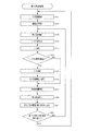
- the CPU executes a program corresponding to the flowchart shown in FIG.
- the RAM temporarily stores variables necessary for executing the program.
- the storage unit 50a is configured by a nonvolatile memory or the like, and stores the program and “substrate position”, “lead position”, and “lead intermediate position” described later.
- the control unit 50 controls these by outputting commands to the servomotors, actuators, and switching valves of the tape feeder 21, the board transport device 10, and the component insertion unit 40.
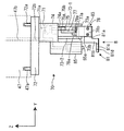
- the gripping device 70 includes a main body 71, an attachment 72, a pair of extending members 73-1, 73-2, a first cylinder 74, a first link member 75, a second link member 76, a third link member 77, a first One clamp mounting member 78, second clamp mounting member 79, first clamp member 81, second clamp member 82, and second cylinder 85 are provided.
- the surface of the gripping device 70 has a dark color such as black.
- the main body 71 has a block shape.
- An attachment portion 72 is attached to the upper end surface of the main body portion 71.
- a plurality of positioning protrusions 72 a are attached to the upper surface of the attachment portion 72.
- the positioning device 72 is positioned on the mounting member 47 by inserting the positioning projection 72 a into a positioning hole 47 a formed at the lower end of the mounting member 47.
- the gripping device 70 is attached to the attachment member 47 by a fastening member such as a screw or suction by air.
- an air flow path 72b is formed in the mounting portion 72.
- the air flow path 72 b opens at the upper end surface of the mounting portion 72, connects to the opening of the air flow path 47 b formed in the mounting member 47, and connects to the air flow path 71 a formed in the main body portion 71. ing.
- the air flow path 47b is connected to an air supply source (not shown) that supplies negative pressure or positive pressure air. The switching between the negative pressure and the positive pressure is performed by a switching valve that operates according to a command from the control unit 50.
- the pair of extending members 73-1 and 73-2 are opposed to each other with a space therebetween and extend downward from the lower end surface of the main body 71.
- First fulcrums 73a and 73b are formed at the lower ends of the extending members 73-1 and 73-2, respectively.
- the first cylinder 74 is attached in the main body 71.
- the first cylinder 74 has a first shaft 74a that protrudes downward from the lower end surface of the main body 71 and slides up and down by air.
- the first shaft 74a is disposed between the pair of extending members 73-1 and 73-2.
- the first cylinder 74 is connected to an air flow path 71 a formed in the main body 71.
- the first link member 75 is attached to the lower end of the first shaft 74a.
- the first link member 75 has a rod shape, and its longitudinal direction is the horizontal direction.
- a second fulcrum 75a and a third fulcrum 75b are formed.
- the upper end of the second link member 76 is pivotally attached to the second fulcrum 75a of the first link member 75.
- the second link member 76 has a rod shape, and its longitudinal direction is a vertical direction.
- a fourth fulcrum 76 a is formed at the lower end of the second link member 76.
- the upper end of the third link member 77 is pivotally attached to the third fulcrum 75b of the first link member 75.
- the third link member 77 has a rod shape, and its longitudinal direction is a vertical direction.
- a fifth fulcrum 77 a is formed at the lower end of the third link member 77.
- the first clamp mounting member 78 includes a base arm 78a and a mounting arm 78b connected to the tip of the base arm 78a.
- the first clamp mounting member 78 is bent at an intermediate portion thereof, and the longitudinal directions of the base arm 78a and the mounting arm 78b are different.
- the base end of the base arm 78 a is pivotally attached to the fourth fulcrum 76 a of the second link member 76.
- the connecting portion between the base arm 78a and the mounting arm 78b is pivotally attached to the first fulcrums 73a and 73b of the extending members 73-1 and 73-2.
- the second clamp mounting member 79 includes a base arm 79a and a mounting arm 79b connected to the tip of the base arm 79a.
- the second clamp attachment member 79 is bent at an intermediate portion thereof, and the longitudinal directions of the base arm 79a and the attachment arm 79b are different.
- the base end of the base arm 79 a is pivotally attached to the fifth fulcrum 77 a of the third link member 77.
- the connecting portion between the base arm 79a and the mounting arm 79b is pivotally attached to the first fulcrums 73a and 73b of the extending members 73-1 and 73-2.
- the first clamp mounting member 78 and the second clamp mounting member 79 intersect at the first fulcrum 73a, 73b.
- the 1st clamp member 81 is comprised from the attaching part 81a, the connection part 81b, and the 1st holding part 81c, and these are integrally formed.
- the attachment portion 81a is positioned and attached to the attachment arm 78b of the first clamp attachment member 78 by a plurality of fastening members 83 such as screws.
- the 1st holding part 81c is rod-shaped, The longitudinal direction is a horizontal direction.
- the connection portion 81b extends downward from the attachment portion 81a and connects the attachment portion 81a and the first gripping portion 81c.
- the second clamp member 82 includes an attachment portion 82a, a connection portion 82b, and a second gripping portion 82c, which are integrally formed.
- the attachment portion 82a is positioned and attached to the attachment arm 79b of the second clamp attachment member 79 by a plurality of fastening members 83 such as screws.
- the 2nd holding part 82c is rod shape, and the longitudinal direction is a horizontal direction.
- the connection part 82b extends downward from the attachment part 82a and connects the attachment part 82a and the second gripping part 82c.
- the first gripping portion 81c and the second gripping portion 82c are opposed to each other.
- the first shaft 74a slides downward, and the first link member 75, the second link member 76, the third link member 77, and the first clamp mounting member 78.
- the first gripping portion 81c and the second gripping portion 82c are opened (separated) by the link operation of the second clamp mounting member 79 (the state shown in FIGS. 4 and 6).
- negative pressure air is supplied to the first cylinder 74, the first shaft 74a slides upward, and the first link member 75, the second link member 76, the third link member 77, and the first clamp.
- the first gripping portion 81c and the second gripping portion 82c are closed by the link operation of the mounting member 78 and the second clamp mounting member 79 (the state shown in FIG. 7).
- the second cylinder 85 is attached to the main body 71.
- the second cylinder 85 is connected to the air flow path 72b.
- the second cylinder 85 has a second shaft 85a that protrudes downward from its lower end and slides in the vertical direction.
- the second shaft 85a is located above the first gripping portion 81c and the second gripping portion 82c in a state where the first gripping portion 81c and the second gripping portion 82c are closed.
- positive pressure air is supplied to the second cylinder 85
- the second shaft 85a slides downward and approaches the first gripping portion 81c and the second gripping portion 82c.
- negative pressure air is supplied to the second cylinder 85, the second shaft 85a slides upward.
- a pair of lead position restricting grooves 81d is formed on the surface of the first gripping portion 81c facing the second gripping portion 82c.
- the shape of the lead position regulating groove 81d is a V groove.
- the distance a between the bottoms of the pair of lead position regulating grooves 81d is the same as the distance b (shown in FIG. 2) between the pair of leads 802 of the insertion part 800, and the pair of insertions into which the pair of leads 802 are inserted. It is the same as the distance between the holes 700a.
- a pair of lead position restricting projections 82d is formed at the same position as the lead position restricting groove 81d in the longitudinal direction of the surface of the second gripping part 82c facing the first grasping part 81c. As shown in FIG. 7, when the first gripping portion 81c and the second gripping portion 82c are closed, the pair of lead position restricting projections 82d enters the pair of lead position restricting grooves 81d.
- control unit 50 carries in the board 700 from the component insertion machine 100 on the upstream side by controlling the servo motor that drives the conveyor of the board carrying apparatus 10. Next, the control unit 50 controls the servo motor that drives the clamp of the substrate transport apparatus 10 to position and fix the loaded substrate 700 with the clamp.
- the program proceeds to S12.
- the control unit 50 controls the Y-axis servo motor 44 and the X-axis servo motor to move the substrate imaging device 46 onto the reference mark 701 formed on the substrate 700.
- the reference mark 701 is imaged.
- the control unit 50 performs image analysis of the reference mark 701 imaged by the board imaging device 46 to thereby detect the position (X of the board 700) on the coordinates of the component insertion machine 100 (hereinafter referred to as “insertion machine coordinates”). , Including the position in the Y direction and the inclination, hereinafter abbreviated as “substrate position”), and stores the “substrate position” in the storage unit 50a.
- the program proceeds to S13.
- control unit 50 controls the sprocket servomotor to rotate the sprocket, feed the carrier tape 900 by one pitch, and supply the insertion component 800 to the component supply unit 21a.
- the program proceeds to S14.
- control unit 50 causes the pair of leads 802 of the insertion component 800 supplied to the component supply unit 21a to be gripped by the gripping device during lead cutting.
- the control unit 50 controls the Y-axis servo motor 44 and the X-axis servo motor to move the gripping device 70 to the component supply unit 21a, and the first gripping portion 81c and the second gripping portion 82c are separated from each other.
- the pair of leads 802 of the insertion component 800 supplied to the component supply unit 21a is sandwiched between the first holding unit 81c and the second holding unit 82c.
- the control unit 50 controls the switching valve to supply negative pressure air to the gripping device 70, thereby supplying negative pressure to the first cylinder 74, and the first gripping portion 81 c and the second gripping portion.
- the pair of leads 802 are gripped by the part 82c (state shown in FIGS. 2 and 7).
- the pair of leads 802 are respectively pushed into the lead position restricting grooves 81d by the pair of lead position restricting protrusions 82d. For this reason, even if the lead 802 of the insertion component 800 supplied to the component supply unit 21a is deformed, the lead 802 is pushed into the lead position regulating groove 81d, so that the distance between the pair of leads 802 is an appropriate distance between the leads.
- the lead 802 is positioned at the first gripping portion 81c and the second gripping portion 82c.
- the control unit 50 releases the gripping of the pair of leads 802 by the gripping device during lead cutting.
- S15 ends, the program proceeds to S16.
- the gripping device 70 is moved onto the lead imaging device 60 by controlling the Y-axis servomotor 44 and the X-axis servomotor.
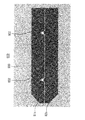
- the control unit 50 images the pair of leads 802 gripped by the first gripping portion 81c and the second gripping portion 82c from below with the lead imaging device 60, and generates a lead-containing image 600 (shown in FIG. 9). get.
- the lead-containing image 600 of FIG. 9 the brightest part is the lead 802
- the darkest part is the first gripping part 81c and the second gripping part 82c
- the other part is the background 999.
- the luminance values of the imaged portions of the first gripping portion 81 c and the second gripping portion 82 c are values close to the luminance value of the background 999 compared to the luminance value of the lead 802. If there is a sufficient difference between the luminance value of the lead 802 and the luminance value of a portion other than the lead 802, when the lead-containing image 600 is processed and the position of the lead 802 is recognized, the portion other than the lead 802 is detected. It is possible to prevent erroneous recognition of the lead 802.
- the luminance value of the part imaged by the lead imaging device 60 of the first grip part 81c and the second grip part 82c can be adjusted by changing any of the material, the color, and the surface processing method.
- the control unit 50 (lead position detection unit) performs gray processing for classifying the pixels of the lead-containing image 600 into a predetermined number of gradations from white to black, and detects the outer edge of the lead 802, whereby The center position of the tips of the pair of leads 802 (hereinafter referred to as “lead position”) on the “insertion machine coordinates” or “captured image coordinates” is acquired.
- the control unit 50 calculates an intermediate position of the lead 802 (hereinafter referred to as “lead intermediate position”) from the pair of “lead positions”, and stores the “lead intermediate position” in the storage unit 50a.
- the program proceeds to S19.
- the control unit 50 based on the “substrate position” and the “lead intermediate position” stored in the storage unit 50a, the pair of leads 802 gripped by the first gripping portion 81c and the second gripping portion 82c.
- the relative position with respect to the insertion hole 700a into which the pair of leads 802 are inserted is calculated, and the movement amount of the insertion part 800 gripped by the gripping device 70 (hereinafter referred to as “part movement amount”) is calculated.
- part movement amount the program proceeds to S20.
- the control unit 50 controls the X-axis servo motor and the Y-axis servo motor 44 to move the insertion part 800 gripped by the gripping device 70 by the “part movement amount” calculated in S19.
- the pair of leads 802 are moved directly above the pair of insertion holes 700a.
- the control unit 50 controls the Z-axis servo motor to lower the gripping device 70, and as shown in FIG. 10, the pair of leads 802 gripped by the gripping device 70 is paired with a pair of insertion holes 700a. Insert into.
- the program proceeds to S21.
- the control unit 50 controls the switching valve to supply positive pressure air to the gripping device 70, thereby supplying positive pressure air to the first cylinder 74 and the second cylinder 85, and clamping. While opening the members 81 and 82 and pressing the main body 801 with the second shaft 85a as shown in FIG. 10, the insertion component 800 is pushed into the substrate 700 side. As a result, the lead 802 is reliably inserted into the insertion hole 700a.
- the program proceeds to S22.
- the lead 802 is imaged in a state where the lead is held by the clamp members 81 and 82 (S17 in FIG. 8), and the “lead position” is detected (S18).
- the inclination of the insertion part 800 can be suppressed.
- the insertion part 800 other than the tip of the lead 802 is concealed by the clamp members 81 and 82 (FIG. 7)
- the base portion of the main body 801 from which the metallic lead 802 extends does not appear in the lead-containing image 600 ( FIG. 9). Therefore, the lead 802 can be identified from other parts, the tip of the lead 802 can be recognized, and the “lead position” can be detected.
- the control unit 50 moves the gripping device 70 by the X, Y robot (moving device) based on the “lead position” (S20). Therefore, when the gripping device 70 is detached from the mounting member 47 or when the clamp members 81 and 82 are replaced, even if the position where the clamp member 81 or 82 grips the lead 802 is misaligned, or the gripping device 70 In addition, the lead 802 can be surely inserted into the insertion hole 700a regardless of the manufacturing errors of the X and Y robots, and the insertion component 800 can be reliably inserted and mounted on the electronic substrate 700. As described above, the “lead position” is detected by the lead imaging device 60, and the insertion mounting is performed based on the “lead position”. Therefore, the position of the lead position regulating groove 81d of the first clamp member 81 is determined with high accuracy. Therefore, it is possible to reduce the man-hours necessary for the management, and to reduce the cost of insertion mounting.
- the first clamp member 81 is formed with a lead position restricting groove 81d for restricting the position of the lead 802 relative to the clamp members 81 and 82 when the lead 802 is gripped.
- the lead 802 is corrected by the lead position regulating groove 81d, so that the distance between the leads is corrected to an appropriate value, so that the lead 802 is securely inserted into the insertion hole. 700a can be inserted.
- the “part movement amount” is calculated based on the “lead position” stored in the storage unit 50a ( S19), the lead 802 is inserted into the insertion hole (S20).
- the tip of the lead 802 is corrected by the lead position regulating groove 81d (S14, FIG. 7).
- the tip of the lead 802 of the insertion component 800 supplied to the component supply unit 21a is corrected to the “lead position” without detecting the “lead position” every time.
- the lead 802 can be reliably inserted into the insertion hole 700a.
- the tact time for inserting the lead 802 into the insertion hole 700a can be shortened, and the insertion mounting Productivity is improved.
- the lead position regulating groove 81d is a V-groove.
- the lead 802 is gripped by the clamp members 81 and 82, the lead 802 is pushed into the bottom side of the lead position restricting groove 81d which is the V groove by the lead position restricting projection 82d, and the lead 802 is surely corrected. Can do.
- the lead 802 having a different wire diameter can be handled.
- the base of the insertion component 800 from which the lead 802 extends is a clamp member.
- the gripping device 70 is configured to be hidden by 81 and 82.
- the tip of the lead 802 can be reliably recognized, and the "lead” The “position” can be detected.
- the pair of clamp members 81 and 82 are dark, the pair of clamp members 81 and 82 have a light / dark difference with respect to the lead 802. As a result, the leading end of the lead 802 and the clamp members 81 and 82 can be reliably identified, the leading end of the lead 802 can be reliably recognized, and the “lead position” can be reliably detected.
- the lead position restricting groove 81 d is formed only in the first clamp member 81. However, there is no problem even in an embodiment in which lead position restricting grooves are formed in both the first clamp member 81 and the second clamp member 82. In the embodiment described above, the lead position restricting groove 81d is a V groove, but the lead position restricting groove 81d may be a U groove or the like.
- a “lead intermediate position” is calculated from a pair of “lead positions”.
- the embodiment may calculate the “component movement amount” from the “board position” and the pair of “lead positions” without calculating the “lead intermediate position”.
- the lead imaging device 60 is attached to the base 41.
- the lead imaging device 60 may be an embodiment provided in the X-axis slide 45 or the gripping device 70.
Landscapes
- Engineering & Computer Science (AREA)
- Manufacturing & Machinery (AREA)
- Microelectronics & Electronic Packaging (AREA)
- Operations Research (AREA)
- Supply And Installment Of Electrical Components (AREA)
- Automatic Assembly (AREA)
Abstract
Priority Applications (5)
| Application Number | Priority Date | Filing Date | Title |
|---|---|---|---|
| PCT/JP2013/071436 WO2015019456A1 (fr) | 2013-08-07 | 2013-08-07 | Appareil de détection de position de fil et machine d'insertion de composant |
| CN201380078711.4A CN105453717B (zh) | 2013-08-07 | 2013-08-07 | 引脚位置检测装置及元件插入机 |
| JP2015530613A JP6262736B2 (ja) | 2013-08-07 | 2013-08-07 | 部品挿入機 |
| EP13890896.7A EP3032932B1 (fr) | 2013-08-07 | 2013-08-07 | Appareil de détection de position de fil et machine d'insertion de composant |
| US14/910,589 US10285318B2 (en) | 2013-08-07 | 2013-08-07 | Lead position detecting apparatus and component inserting machine |
Applications Claiming Priority (1)
| Application Number | Priority Date | Filing Date | Title |
|---|---|---|---|
| PCT/JP2013/071436 WO2015019456A1 (fr) | 2013-08-07 | 2013-08-07 | Appareil de détection de position de fil et machine d'insertion de composant |
Publications (1)
| Publication Number | Publication Date |
|---|---|
| WO2015019456A1 true WO2015019456A1 (fr) | 2015-02-12 |
Family
ID=52460824
Family Applications (1)
| Application Number | Title | Priority Date | Filing Date |
|---|---|---|---|
| PCT/JP2013/071436 Ceased WO2015019456A1 (fr) | 2013-08-07 | 2013-08-07 | Appareil de détection de position de fil et machine d'insertion de composant |
Country Status (5)
| Country | Link |
|---|---|
| US (1) | US10285318B2 (fr) |
| EP (1) | EP3032932B1 (fr) |
| JP (1) | JP6262736B2 (fr) |
| CN (1) | CN105453717B (fr) |
| WO (1) | WO2015019456A1 (fr) |
Cited By (8)
| Publication number | Priority date | Publication date | Assignee | Title |
|---|---|---|---|---|
| CN107205335A (zh) * | 2016-03-17 | 2017-09-26 | 深圳市堃琦鑫华股份有限公司 | 一种自动化插件方法 |
| JPWO2017017730A1 (ja) * | 2015-07-24 | 2018-05-17 | 株式会社Fuji | 部品フィーダ |
| JPWO2017017729A1 (ja) * | 2015-07-24 | 2018-05-17 | 株式会社Fuji | 部品フィーダ |
| WO2018134912A1 (fr) * | 2017-01-18 | 2018-07-26 | 株式会社Fuji | Machine d'insertion de composant |
| CN108370663A (zh) * | 2015-12-24 | 2018-08-03 | 株式会社富士 | 信息处理装置、安装装置、信息处理方法及元件把持用具 |
| JP2020080434A (ja) * | 2020-03-04 | 2020-05-28 | 株式会社Fuji | 部品チャック装置 |
| JP2021044591A (ja) * | 2015-12-24 | 2021-03-18 | 株式会社Fuji | 実装装置 |
| JPWO2020084663A1 (ja) * | 2018-10-22 | 2021-03-18 | 株式会社Fuji | 電気部品供給装置、および電気部品供給方法 |
Families Citing this family (13)
| Publication number | Priority date | Publication date | Assignee | Title |
|---|---|---|---|---|
| JP6764259B2 (ja) * | 2016-05-31 | 2020-09-30 | 川崎重工業株式会社 | 電子部品挿入装置 |
| JP6761477B2 (ja) * | 2016-09-01 | 2020-09-23 | 株式会社Fuji | 部品実装装置および位置認識方法 |
| US11064639B2 (en) * | 2016-12-01 | 2021-07-13 | Fuji Corporation | Operation machine to control holding head |
| JP6534016B2 (ja) * | 2017-03-06 | 2019-06-26 | パナソニックIpマネジメント株式会社 | 部品実装装置及び部品実装方法 |
| CN108575086A (zh) * | 2017-03-08 | 2018-09-25 | 台达电子电源(东莞)有限公司 | 电子元器件接脚位置采集装置、识别装置及自动插件机 |
| JP7278706B2 (ja) * | 2017-11-27 | 2023-05-22 | 川崎重工業株式会社 | 把持装置及び実装装置 |
| JP7116596B2 (ja) * | 2018-05-31 | 2022-08-10 | 川崎重工業株式会社 | リード線挿入装置およびリード線挿入方法 |
| FR3092782B1 (fr) * | 2019-02-14 | 2021-07-09 | Mga Tech | Procede de prehension de composants electroniques comportant des broches |
| CN110381721B (zh) * | 2019-07-16 | 2020-07-31 | 深圳市中禾旭精密机械有限公司 | 一种卧式智能全自动高速插装系统 |
| CN114158249B (zh) * | 2020-09-08 | 2024-04-26 | 台达电子工业股份有限公司 | 自动插件设备 |
| TWI776229B (zh) * | 2020-09-08 | 2022-09-01 | 台達電子工業股份有限公司 | 自動插件設備 |
| CN112197875B (zh) * | 2020-11-04 | 2025-11-04 | 深圳市美思先端电子有限公司 | 用于红外传感器的测试系统 |
| JP7613198B2 (ja) * | 2021-03-26 | 2025-01-15 | セイコーエプソン株式会社 | ロボットシステムの制御方法、ロボットシステムおよびプログラム |
Citations (5)
| Publication number | Priority date | Publication date | Assignee | Title |
|---|---|---|---|---|
| JPS62143497A (ja) | 1985-12-18 | 1987-06-26 | 株式会社日立製作所 | 電子部品の自動組み込み装置 |
| JPH0563396A (ja) * | 1991-09-02 | 1993-03-12 | Tdk Corp | 電子部品挿入方法及び装置 |
| JPH0637492A (ja) * | 1992-07-15 | 1994-02-10 | Matsushita Electric Ind Co Ltd | 電子部品挿入装置 |
| JPH0758498A (ja) * | 1993-08-16 | 1995-03-03 | Tdk Corp | 電子部品の挿入方法及び装置 |
| JP2004103994A (ja) * | 2002-07-19 | 2004-04-02 | Matsushita Electric Ind Co Ltd | 部品挿入装置及び挿入方法 |
Family Cites Families (11)
| Publication number | Priority date | Publication date | Assignee | Title |
|---|---|---|---|---|
| US4705081A (en) * | 1986-02-21 | 1987-11-10 | Hewlett-Packard Company | System for sensing and forming objects such as leads of electronic components |
| JPH0249499A (ja) * | 1988-08-11 | 1990-02-19 | Hitachi Ltd | 電子部品の自動挿入装置 |
| JPH03284900A (ja) * | 1990-03-30 | 1991-12-16 | Taiyo Yuden Co Ltd | リード線付電子部品のリード線クランプ方法 |
| US5052606A (en) * | 1990-06-29 | 1991-10-01 | International Business Machines Corp. | Tape automated bonding feeder |
| JPH0521996A (ja) * | 1991-07-17 | 1993-01-29 | Matsushita Electric Ind Co Ltd | 電子部品挿入装置 |
| JPH0661273A (ja) * | 1992-08-06 | 1994-03-04 | Mitsubishi Electric Corp | リードフレーム処理方法及びそのための装置 |
| CN1299875C (zh) * | 1998-05-11 | 2007-02-14 | 松下电器产业株式会社 | 零件安装机 |
| JP3387881B2 (ja) * | 1999-03-17 | 2003-03-17 | ティーディーケイ株式会社 | 電子部品挿入ヘッドおよび電子部品挿入装置 |
| JP4576062B2 (ja) * | 2001-03-21 | 2010-11-04 | 富士機械製造株式会社 | リード位置検出方法,電気部品装着方法およびリード位置検出装置 |
| JP2003100781A (ja) * | 2001-09-25 | 2003-04-04 | Mitsubishi Electric Corp | 半導体製造装置、半導体装置の製造方法及び半導体装置 |
| DE112006001968T5 (de) * | 2005-08-22 | 2008-07-31 | Matsushita Electric Industrial Co. Ltd. | Komponentenmontageverfahren |
-
2013
- 2013-08-07 EP EP13890896.7A patent/EP3032932B1/fr active Active
- 2013-08-07 CN CN201380078711.4A patent/CN105453717B/zh active Active
- 2013-08-07 US US14/910,589 patent/US10285318B2/en active Active
- 2013-08-07 WO PCT/JP2013/071436 patent/WO2015019456A1/fr not_active Ceased
- 2013-08-07 JP JP2015530613A patent/JP6262736B2/ja active Active
Patent Citations (5)
| Publication number | Priority date | Publication date | Assignee | Title |
|---|---|---|---|---|
| JPS62143497A (ja) | 1985-12-18 | 1987-06-26 | 株式会社日立製作所 | 電子部品の自動組み込み装置 |
| JPH0563396A (ja) * | 1991-09-02 | 1993-03-12 | Tdk Corp | 電子部品挿入方法及び装置 |
| JPH0637492A (ja) * | 1992-07-15 | 1994-02-10 | Matsushita Electric Ind Co Ltd | 電子部品挿入装置 |
| JPH0758498A (ja) * | 1993-08-16 | 1995-03-03 | Tdk Corp | 電子部品の挿入方法及び装置 |
| JP2004103994A (ja) * | 2002-07-19 | 2004-04-02 | Matsushita Electric Ind Co Ltd | 部品挿入装置及び挿入方法 |
Non-Patent Citations (1)
| Title |
|---|
| See also references of EP3032932A4 |
Cited By (15)
| Publication number | Priority date | Publication date | Assignee | Title |
|---|---|---|---|---|
| EP3328177A4 (fr) * | 2015-07-24 | 2018-05-30 | Fuji Machine Mfg. Co., Ltd. | Dispositif d'alimentation en composants |
| JPWO2017017730A1 (ja) * | 2015-07-24 | 2018-05-17 | 株式会社Fuji | 部品フィーダ |
| JPWO2017017729A1 (ja) * | 2015-07-24 | 2018-05-17 | 株式会社Fuji | 部品フィーダ |
| EP3397041A4 (fr) * | 2015-12-24 | 2018-12-26 | Fuji Corporation | Dispositif de traitement d'informations, dispositif de montage, procédé de traitement d'informations, et outil de maintien de composants |
| CN108370663A (zh) * | 2015-12-24 | 2018-08-03 | 株式会社富士 | 信息处理装置、安装装置、信息处理方法及元件把持用具 |
| JP2021044591A (ja) * | 2015-12-24 | 2021-03-18 | 株式会社Fuji | 実装装置 |
| US11039559B2 (en) | 2015-12-24 | 2021-06-15 | Fuji Corporation | Information processing apparatus, mounting apparatus, information processing method, and component gripper |
| CN108370663B (zh) * | 2015-12-24 | 2021-06-29 | 株式会社富士 | 具备信息处理装置和元件把持用具的系统、具备信息处理装置和安装装置的系统、信息处理方法 |
| JP7365324B2 (ja) | 2015-12-24 | 2023-10-19 | 株式会社Fuji | 実装装置 |
| CN107205335A (zh) * | 2016-03-17 | 2017-09-26 | 深圳市堃琦鑫华股份有限公司 | 一种自动化插件方法 |
| WO2018134912A1 (fr) * | 2017-01-18 | 2018-07-26 | 株式会社Fuji | Machine d'insertion de composant |
| JPWO2018134912A1 (ja) * | 2017-01-18 | 2019-11-07 | 株式会社Fuji | 部品挿入機 |
| JPWO2020084663A1 (ja) * | 2018-10-22 | 2021-03-18 | 株式会社Fuji | 電気部品供給装置、および電気部品供給方法 |
| JP7012868B2 (ja) | 2018-10-22 | 2022-01-28 | 株式会社Fuji | 電気部品供給装置、および電気部品供給方法 |
| JP2020080434A (ja) * | 2020-03-04 | 2020-05-28 | 株式会社Fuji | 部品チャック装置 |
Also Published As
| Publication number | Publication date |
|---|---|
| EP3032932A4 (fr) | 2016-09-14 |
| CN105453717A (zh) | 2016-03-30 |
| JP6262736B2 (ja) | 2018-01-17 |
| EP3032932A1 (fr) | 2016-06-15 |
| JPWO2015019456A1 (ja) | 2017-03-02 |
| US10285318B2 (en) | 2019-05-07 |
| EP3032932B1 (fr) | 2017-11-22 |
| US20160198601A1 (en) | 2016-07-07 |
| CN105453717B (zh) | 2019-05-10 |
Similar Documents
| Publication | Publication Date | Title |
|---|---|---|
| JP6262736B2 (ja) | 部品挿入機 | |
| US11090774B2 (en) | Automatic assembling system and method | |
| EP2840597B1 (fr) | Système et procédé de montage automatique | |
| US20160203890A1 (en) | Production device for wire harness and production method therefor | |
| WO2015029123A1 (fr) | Dispositif de montage de composants | |
| US11304350B2 (en) | Board work machine and insertion method | |
| EP4045245B1 (fr) | Système d'insertion de module pour assemblage robotique | |
| JP2016219474A (ja) | 部品取出し装置および部品取出し方法ならびに部品実装装置 | |
| CN112449569B (zh) | 部件供给装置以及部件安装装置 | |
| JP2016219472A (ja) | 部品取出し装置および部品取出し方法ならびに部品実装装置 | |
| JP6442029B2 (ja) | 部品挿入機 | |
| CN105283063A (zh) | 电子部件安装装置以及电子部件安装方法 | |
| EP3439449A1 (fr) | Dispositif de vérification du fonctionnement d'une machine à monter un composant électronique | |
| US11039559B2 (en) | Information processing apparatus, mounting apparatus, information processing method, and component gripper | |
| CN114554830B (zh) | 作业机及安装方法 | |
| EP3771310B1 (fr) | Dispositif de montage de composant | |
| JP2016219473A (ja) | 部品取出し装置および部品取出し方法ならびに部品実装装置 | |
| JP5971930B2 (ja) | 電子部品実装装置 | |
| JP6952135B2 (ja) | ラジアルテープフィーダ | |
| CN110113931B (zh) | 确定电子元件取向的方法、传感器系统及装配机 | |
| JPWO2018100706A1 (ja) | 作業機 | |
| JPWO2018189862A1 (ja) | 作業機 | |
| JP6312814B2 (ja) | 電子回路組立装置 | |
| JPH0983199A (ja) | 部品実装装置及びその実装方法 | |
| JP2022000320A (ja) | 部品組み付け装置 |
Legal Events
| Date | Code | Title | Description |
|---|---|---|---|
| WWE | Wipo information: entry into national phase |
Ref document number: 201380078711.4 Country of ref document: CN |
|
| 121 | Ep: the epo has been informed by wipo that ep was designated in this application |
Ref document number: 13890896 Country of ref document: EP Kind code of ref document: A1 |
|
| REEP | Request for entry into the european phase |
Ref document number: 2013890896 Country of ref document: EP |
|
| WWE | Wipo information: entry into national phase |
Ref document number: 2013890896 Country of ref document: EP |
|
| ENP | Entry into the national phase |
Ref document number: 2015530613 Country of ref document: JP Kind code of ref document: A |
|
| WWE | Wipo information: entry into national phase |
Ref document number: 14910589 Country of ref document: US |
|
| NENP | Non-entry into the national phase |
Ref country code: DE |