WO2016181466A1 - Système de distribution, dispositif de commande et procédé de commande - Google Patents
Système de distribution, dispositif de commande et procédé de commande Download PDFInfo
- Publication number
- WO2016181466A1 WO2016181466A1 PCT/JP2015/063515 JP2015063515W WO2016181466A1 WO 2016181466 A1 WO2016181466 A1 WO 2016181466A1 JP 2015063515 W JP2015063515 W JP 2015063515W WO 2016181466 A1 WO2016181466 A1 WO 2016181466A1
- Authority
- WO
- WIPO (PCT)
- Prior art keywords
- dispenser
- robot
- liquid
- tip
- position information
- Prior art date
- Legal status (The legal status is an assumption and is not a legal conclusion. Google has not performed a legal analysis and makes no representation as to the accuracy of the status listed.)
- Ceased
Links
Images









Classifications
-
- G—PHYSICS
- G01—MEASURING; TESTING
- G01N—INVESTIGATING OR ANALYSING MATERIALS BY DETERMINING THEIR CHEMICAL OR PHYSICAL PROPERTIES
- G01N35/00—Automatic analysis not limited to methods or materials provided for in any single one of groups G01N1/00 - G01N33/00; Handling materials therefor
- G01N35/10—Devices for transferring samples or any liquids to, in, or from, the analysis apparatus, e.g. suction devices, injection devices
- G01N35/1009—Characterised by arrangements for controlling the aspiration or dispense of liquids
- G01N35/1011—Control of the position or alignment of the transfer device
-
- B—PERFORMING OPERATIONS; TRANSPORTING
- B01—PHYSICAL OR CHEMICAL PROCESSES OR APPARATUS IN GENERAL
- B01L—CHEMICAL OR PHYSICAL LABORATORY APPARATUS FOR GENERAL USE
- B01L3/00—Containers or dishes for laboratory use, e.g. laboratory glassware; Droppers
- B01L3/02—Burettes; Pipettes
- B01L3/021—Pipettes, i.e. with only one conduit for withdrawing and redistributing liquids
- B01L3/0217—Pipettes, i.e. with only one conduit for withdrawing and redistributing liquids of the plunger pump type
- B01L3/0237—Details of electronic control, e.g. relating to user interface
-
- B—PERFORMING OPERATIONS; TRANSPORTING
- B25—HAND TOOLS; PORTABLE POWER-DRIVEN TOOLS; MANIPULATORS
- B25J—MANIPULATORS; CHAMBERS PROVIDED WITH MANIPULATION DEVICES
- B25J15/00—Gripping heads and other end effectors
- B25J15/0019—End effectors other than grippers
-
- B—PERFORMING OPERATIONS; TRANSPORTING
- B25—HAND TOOLS; PORTABLE POWER-DRIVEN TOOLS; MANIPULATORS
- B25J—MANIPULATORS; CHAMBERS PROVIDED WITH MANIPULATION DEVICES
- B25J9/00—Program-controlled manipulators
- B25J9/0084—Program-controlled manipulators comprising a plurality of manipulators
- B25J9/0087—Dual arms
-
- B—PERFORMING OPERATIONS; TRANSPORTING
- B25—HAND TOOLS; PORTABLE POWER-DRIVEN TOOLS; MANIPULATORS
- B25J—MANIPULATORS; CHAMBERS PROVIDED WITH MANIPULATION DEVICES
- B25J9/00—Program-controlled manipulators
- B25J9/16—Program controls
- B25J9/1679—Program controls characterised by the tasks executed
-
- B—PERFORMING OPERATIONS; TRANSPORTING
- B25—HAND TOOLS; PORTABLE POWER-DRIVEN TOOLS; MANIPULATORS
- B25J—MANIPULATORS; CHAMBERS PROVIDED WITH MANIPULATION DEVICES
- B25J9/00—Program-controlled manipulators
- B25J9/16—Program controls
- B25J9/1679—Program controls characterised by the tasks executed
- B25J9/1684—Tracking a line or surface by means of sensors
-
- B—PERFORMING OPERATIONS; TRANSPORTING
- B25—HAND TOOLS; PORTABLE POWER-DRIVEN TOOLS; MANIPULATORS
- B25J—MANIPULATORS; CHAMBERS PROVIDED WITH MANIPULATION DEVICES
- B25J9/00—Program-controlled manipulators
- B25J9/16—Program controls
- B25J9/1694—Program controls characterised by use of sensors other than normal servo-feedback from position, speed or acceleration sensors, perception control, multi-sensor controlled systems, sensor fusion
- B25J9/1697—Vision controlled systems
-
- C—CHEMISTRY; METALLURGY
- C12—BIOCHEMISTRY; BEER; SPIRITS; WINE; VINEGAR; MICROBIOLOGY; ENZYMOLOGY; MUTATION OR GENETIC ENGINEERING
- C12M—APPARATUS FOR ENZYMOLOGY OR MICROBIOLOGY; APPARATUS FOR CULTURING MICROORGANISMS FOR PRODUCING BIOMASS, FOR GROWING CELLS OR FOR OBTAINING FERMENTATION OR METABOLIC PRODUCTS, i.e. BIOREACTORS OR FERMENTERS
- C12M1/00—Apparatus for enzymology or microbiology
-
- G—PHYSICS
- G01—MEASURING; TESTING
- G01N—INVESTIGATING OR ANALYSING MATERIALS BY DETERMINING THEIR CHEMICAL OR PHYSICAL PROPERTIES
- G01N35/00—Automatic analysis not limited to methods or materials provided for in any single one of groups G01N1/00 - G01N33/00; Handling materials therefor
- G01N35/0099—Automatic analysis not limited to methods or materials provided for in any single one of groups G01N1/00 - G01N33/00; Handling materials therefor comprising robots or similar manipulators
-
- Y—GENERAL TAGGING OF NEW TECHNOLOGICAL DEVELOPMENTS; GENERAL TAGGING OF CROSS-SECTIONAL TECHNOLOGIES SPANNING OVER SEVERAL SECTIONS OF THE IPC; TECHNICAL SUBJECTS COVERED BY FORMER USPC CROSS-REFERENCE ART COLLECTIONS [XRACs] AND DIGESTS
- Y10—TECHNICAL SUBJECTS COVERED BY FORMER USPC
- Y10S—TECHNICAL SUBJECTS COVERED BY FORMER USPC CROSS-REFERENCE ART COLLECTIONS [XRACs] AND DIGESTS
- Y10S901/00—Robots
- Y10S901/02—Arm motion controller
- Y10S901/09—Closed loop, sensor feedback controls arm movement
-
- Y—GENERAL TAGGING OF NEW TECHNOLOGICAL DEVELOPMENTS; GENERAL TAGGING OF CROSS-SECTIONAL TECHNOLOGIES SPANNING OVER SEVERAL SECTIONS OF THE IPC; TECHNICAL SUBJECTS COVERED BY FORMER USPC CROSS-REFERENCE ART COLLECTIONS [XRACs] AND DIGESTS
- Y10—TECHNICAL SUBJECTS COVERED BY FORMER USPC
- Y10S—TECHNICAL SUBJECTS COVERED BY FORMER USPC CROSS-REFERENCE ART COLLECTIONS [XRACs] AND DIGESTS
- Y10S901/00—Robots
- Y10S901/30—End effector
-
- Y—GENERAL TAGGING OF NEW TECHNOLOGICAL DEVELOPMENTS; GENERAL TAGGING OF CROSS-SECTIONAL TECHNOLOGIES SPANNING OVER SEVERAL SECTIONS OF THE IPC; TECHNICAL SUBJECTS COVERED BY FORMER USPC CROSS-REFERENCE ART COLLECTIONS [XRACs] AND DIGESTS
- Y10—TECHNICAL SUBJECTS COVERED BY FORMER USPC
- Y10S—TECHNICAL SUBJECTS COVERED BY FORMER USPC CROSS-REFERENCE ART COLLECTIONS [XRACs] AND DIGESTS
- Y10S901/00—Robots
- Y10S901/46—Sensing device
- Y10S901/47—Optical
Definitions
- the present disclosure relates to a dispensing system, a controller, and a control method.
- Patent Document 1 discloses a chip, a liquid feeding device that sucks a sample into the chip or discharges a sample in the chip, a chip transport mechanism, a detection unit that detects the liquid level of the sample, A supply / discharge robot including a liquid feeding power device and a control device for controlling the chip transport mechanism so that the tip end and the sample liquid level are kept in contact with each other based on the liquid level position of the sample during aspiration. It is disclosed.
- This disclosure is intended to provide a dispensing system, a dispensing method, a control device, and a control method capable of performing a more reliable dispensing operation.
- a dispensing system includes a robot that moves a dispenser for sucking a liquid to be dispensed, at least a tip of the dispenser, a liquid level, and a lower level than the liquid level.
- the image processing unit that acquires the position information of the tip of the injection device, and the position information of the tip, the position information of the liquid surface, and the position information of the boundary when the liquid is sucked into the dispenser And a descent controller that controls the robot to lower the dispenser.
- a dispensing system includes a robot that moves a dispenser for sucking a liquid to be dispensed, at least a tip of the dispenser, a liquid level, and a lower level than the liquid level.
- a camera for capturing an image including a non-dispensing object that is positioned, and based on the image, position information on the liquid level, position information on a boundary between the liquid and the non-dispensing object, and dispensing Obtaining the position information of the tip of the injection device, when sucking the liquid into the dispenser, based on the position information of the tip, the position information of the liquid level, and the position information of the boundary, And a circuit configured to perform control of the robot to lower the dispenser.
- the controller according to the present disclosure is based on an image including at least a tip of a dispenser for sucking a liquid to be dispensed, a liquid level of the liquid, and a non-dispensing target positioned below the liquid level.
- An image processing unit for acquiring position information on the liquid level, position information on the boundary between the liquid and the non-dispensing object, and position information on the tip of the dispenser; and the liquid in the dispenser And a descent controller that controls the robot to lower the dispenser based on the position information on the tip, the position information on the liquid level, and the position information on the boundary.
- the control method includes an image including at least a tip portion of a dispenser for sucking a liquid to be dispensed, a liquid level of the liquid, and a non-dispensing target positioned below the liquid level.
- an image including at least a tip portion of a dispenser for sucking a liquid to be dispensed, a liquid level of the liquid, and a non-dispensing target positioned below the liquid level.
- the dispensing system 1 is for performing a dispensing operation for selectively taking out the liquid stored in the container 80.
- the container 80 accommodates an object to be worked by the dispensing system 1.
- the container 80 is formed of a material that can transmit visible light or light of a specific wavelength.
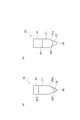
- the container 80 is a microtube, for example, and has a cylindrical side wall 81 and a bottom 82 (see FIGS. 2A and 2B).
- the lower portion 81a of the side wall 81 has a tapered shape that narrows toward the bottom 82 side.
- the container 80 is not limited to such a microtube, and may have any shape as long as it can accommodate an object and can transmit visible light or light of a specific wavelength.
- the object accommodated in the container 80 is separated into a liquid C1 to be dispensed and a non-dispensing object C2 by centrifugation or the like, and the liquid C1 forms a liquid surface SF1, and the non-dispensing object C2 Is located below the liquid level SF1.
- the non-dispensing object C2 include a solid precipitate or a liquid separated from the liquid C1.
- the boundary part BD1 between the liquid C1 and the non-dispensing object C2 is parallel to the liquid surface SF1 (see FIG. 2A).
- the boundary part BD1 may be inclined with respect to the liquid level SF1 (see FIG. 2B).
- the boundary portion BD1 is visible from the outside of the container 80. For example, if the transmissivity of light that can pass through the container 80 is different between the liquid C1 and the non-dispensing object C2, the boundary portion BD1 becomes visible. Even if the refractive index of the light that can pass through the container 80 is different between the liquid C1 and the non-dispensing object C2, the boundary portion BD1 is visible.
- the dispensing system 1 takes out the liquid C1 to be dispensed from the container 80 in a state where the non-dispensing object C2 remains in the container 80, and transfers the liquid C1 to another container 80.
- the non-dispensing object C2 is merely a “non-dispensing object” in the process of dispensing the liquid C1.
- the dispensing system 1 may further dispense the non-dispensing object C2 itself in the step after dispensing the liquid C1.
- each component of the dispensing system 1 will be described.
- the dispensing system 1 includes a robot 10 and a camera 40.
- the robot 10 is used for operations such as moving the dispenser 30.
- the dispenser 30 aspirates the liquid C1 to be dispensed.
- Examples of the dispenser 30 include an electric pipette or syringe that automatically sucks and discharges a liquid by a specific signal or a specific operation.
- the dispenser 30 may not be motorized, and may be a manual syringe or pipette, for example. In this case, as described later, the dispenser 30 may be operated by both arms of the double-armed robot 10.
- the dispenser 30 may be anything as long as it can suck the liquid C1, but the following illustrates a case where the dispenser 30 is an electric pipette.
- the dispenser 30 has a main body 31 and a chip 32.
- the main body 31 incorporates an electric pump, for example, and operates according to a command input.
- the chip 32 is detachably attached to the main body 31.
- the tip 32 has, for example, a pointed cylindrical shape and forms the distal end portion 30 a of the dispenser 30.
- the dispenser 30 decompresses the inside of the chip 32 by the main body 31, thereby sucking the liquid from the tip 30a and pressurizing the inside of the chip 32 to discharge the liquid from the tip 30a.
- the robot 10 may be anything as long as the operation of moving the dispenser 30 can be performed.
- the robot 10 may be a single arm type or a double arm type.
- FIG. 1 illustrates a double-armed robot 10.
- the robot 10 includes a trunk portion 11, a shoulder portion 12, a first arm 13A, and a second arm 13B.
- drum 11 stands with respect to a floor surface.
- the shoulder portion 12 is attached to the upper portion of the trunk portion 11 and is rotatable around a vertical axis.
- the arms 13A and 13B are, for example, serial link type articulated arms, and are attached to both ends of the shoulder portion 12, respectively.
- a gripping mechanism 14 is provided at the ends of the arms 13A and 13B.
- the gripping mechanism 14 is a robot hand having a plurality of finger portions 15, for example, and grips various work objects by opening and closing the finger portions 15.
- the camera 40 captures an image including at least the tip portion 30a of the dispenser 30, the liquid surface SF1 of the liquid C1, and the non-dispensing object C2.
- the camera 40 has an image pickup device such as a CCD (Charge Coupled Device) image sensor or a CMOS (Complementary Metal Oxide Semiconductor) image sensor, picks up an image in response to a command input, and outputs the image data.
- CCD Charge Coupled Device
- CMOS Complementary Metal Oxide Semiconductor
- the dispensing system 1 may further include a table 20.
- the table 20 is attached to the robot 10 and supports an object to be worked by the robot 10.
- the dispensing system 1 may further include a rack 60.
- the rack 60 holds the camera 40 and the container 80 together.
- the rack 60 may be anything as long as the positional relationship between the holding objects can be maintained.
- the rack 60 includes support plates 61A and 61B, a container holding unit 62, a camera holding unit 63, and a handle 65.
- the support plates 61A and 61B have a rectangular shape and are connected so as to be rotatable with respect to each other on one side. For example, one side of the support plates 61 ⁇ / b> A and 61 ⁇ / b> B is connected via a hinge 66.
- the support plates 61 ⁇ / b> A and 61 ⁇ / b> B are arranged on the table 20 such that the support plate 61 ⁇ / b> A overlaps the support plate 61 ⁇ / b> B and the hinge 66 is on the opposite side of the robot 10.
- the support plate 61B may be fixed to the table 20 by bolt fastening or the like. Even in a state where the support plate 61B is fixed to the table 20, the support plate 61A can rotate about the central axis of the hinge 66.
- the container holding part 62, the camera holding part 63, and the light holding part 64 are provided on the support plate 61A.
- the container holding unit 62 holds the container 80.
- the container holding unit 62 holds the container 80 so that the side wall 81 is perpendicular to the support plate 61A.
- the camera holding unit 63 captures an image including at least a part of the liquid level SF1 of the liquid C1 in the container 80, at least a part of the non-dispensing object C2, and the tip part 30a inserted into the container 80.
- the camera 40 is held in a posture that can be done.
- the camera holding unit 63 may be arranged so as to line up with the container holding unit 62 in a direction along the hinge 66, for example. In this case, the support plate 61A can be rotated around the axis line along the direction in which the container holding portion 62 and the light holding portion 64 are arranged.
- the handle 65 is provided on the opposite side of the hinge 66 on the support plate 61A, for example.
- the handle 65 is located on the robot 10 side.
- the handle 65 protrudes upward from the support plate 61 ⁇ / b> A, and its upper portion 65 a projects to the opposite side of the hinge 66.
- the support plate 61A can be rotated around the hinge 66 and the rack 60 can be tilted.
- tilt the rack 60 means that the object to be held in the rack 60 is tilted by tilting a part or the whole of the rack 60.
- the rack 60 may further include a stopper 67.
- the stopper 67 is a member that keeps the inclination of the rack 60 constant.
- the stopper 67 is provided on the opposite side of the hinge 66 on the support plate 61B.
- the stopper 67 protrudes upward from the support plate 61 ⁇ / b> B, and its upper portion 67 a projects to the opposite side of the hinge 66.
- the stopper 67 has a groove 67b facing the hinge 66 side. The edge of the support plate 61A can be fitted into the groove 67b.
- the stopper 67 is rotatable so that the groove 67b is moved closer to and away from the hinge 66.
- the base of the stopper 67 is connected to the support plate 61 ⁇ / b> B via a hinge 68 parallel to the hinge 66.
- FIG. 4B when the stopper 67 is tilted toward the hinge 66 while the support plate 61A is rotated and the edge of the support plate 61A is fitted into the groove 67b, the support plate 61A is restrained. . Thereby, the inclination of the rack 60 is kept constant.
- the dispensing system 1 may further include a backlight 50.
- the backlight 50 irradiates at least an imaging range by the camera 40.
- the light emitted from the backlight 50 may be transmitted through the container 80 and can be detected by the camera 40.
- the backlight 50 may emit red visible light.
- LED Light Emitting Diode
- the backlight 50 may be held on the rack 60 together with the camera 40 and the container 80 in an arrangement in which the container 80 is sandwiched between the backlight 40 and the camera 40.
- the rack 60 may further include a light holding unit 64 provided on the support plate 61 ⁇ / b> A in such a manner that the container holding unit 62 is sandwiched between the rack 60 and the camera holding unit 63.
- the light holding unit 64 holds the backlight 50 in a posture in which light is emitted to the container 80 side.
- the dispensing system 1 further includes a controller 100.
- the controller 100 acquires at least the position information of the liquid level SF1, the position information of the boundary part BD1, and the position information of the tip part 30a of the dispenser 30 based on the image captured by the camera 40.
- the dispenser 30 is lowered based on the position information of the distal end portion 30a, the position information of the liquid surface SF1, and the position information of the boundary portion BD1. Controlling the robot 10 is configured to execute.
- the controller 100 may have a console 70 as a user interface.
- the console 70 includes a monitor 71 and an input device 72 such as a keyboard.
- the console 70 may be a touch panel in which a monitor and an input device are integrated.
- the controller 100 may be of any type as long as it is configured to execute the above-described processing. Hereinafter, the configuration of the controller 100 will be described in detail with reference to FIGS. 1 and 5 to 7. Illustrate.
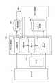
- the controller 100 includes a protocol construction unit 110, an image processing unit 120, a backlight control unit 125, a robot control unit 130, a dispenser control unit 140, a process storage unit 151, and a reference data storage as functional modules. Part 152.
- the protocol construction unit 110 sets work processes of the robot 10 including a plurality of types of dispensing operations, registers them in the process storage unit 151, and registers reference data for dispensing operations in the reference data storage unit 152.
- the reference data is data necessary for controlling the robot 10 and includes image processing data.
- the image processing data includes, for example, an image pattern for image recognition.
- the image processing unit 120 is based on the position information of the liquid surface SF1, the position information of the boundary part BD1, and the position of the tip part 30a. Get information and.
- the backlight control unit 125 switches the backlight 50 on and off. For example, the backlight control unit 125 turns off the backlight in at least a part of the time period when the imaging by the camera 40 is not performed. This can reduce the burden on the operator's eyes.
- the robot control unit 130 controls the robot 10 based on the position information acquired by the image processing unit 120 and the work process registered in the process storage unit 151.
- the dispenser control unit 140 controls the dispenser 30 in synchronization with the control of the robot 10 based on the work process registered in the process storage unit 151. For example, when the dispenser 30 is an electric type, the dispenser control unit 140 turns suction by the dispenser 30 on and off. The dispenser control unit 140 may control the robot 10 so as to operate an on / off switch of the dispenser 30 instead of controlling the dispenser 30 itself. Moreover, when the dispenser 30 is a manual type, the dispenser control part 140 may control the robot 10 so that the dispenser 30 may be operated.
- the dispenser control unit 140 grips the outer cylinder of the syringe by one of the arms 13A and 13B, and the plunger of the syringe by the other of the arms 13A and 13B.
- the robot 10 may be controlled to push and pull.
- the protocol construction unit 110 includes a process setting unit 111, a process confirmation unit 114, an interrupt unit 112, and a reference data registration unit 113.
- the process setting unit 111 sets a work process of the robot 10 including a plurality of types of dispensing work. Specifically, the process setting unit 111 acquires a work process of the robot 10 including a plurality of types of dispensing work from the console 70 and registers it in the process storage unit 151. Thus, the console 70 functions as a user interface for registering work processes.
- the process confirmation unit 114 confirms the work content that the robot control unit 130 intends to execute.
- the interrupting unit 112 stops the robot 10 via the robot control unit 130 when the robot 10 tries to perform a dispensing operation in which the reference data is not registered, and the robot 10 operates after the registration of the reference data. To resume.
- the reference data registration unit 113 displays a reference data setting screen on the console 70 when the interrupt unit 112 stops the robot 10, and acquires and registers the reference data from the console 70.
- the console 70 also functions as a user interface for registering reference data.
- the robot control unit 130 includes a container arrangement control unit 131, a dispenser arrangement control unit 132, a descent control unit 133, a reference distance setting unit 134, a boundary monitoring unit 135, a target position.
- a setting unit 136, a tilt detection unit 137, and a tilt control unit 138 are included.
- the container arrangement control unit 131 controls the robot 10 so that the container 80 is arranged in the field of view of the camera 40.
- the container arrangement control unit 131 controls the arm 13 ⁇ / b> B so that the container 80 is arranged on the container holding unit 62.
- the dispenser arrangement control unit 132 controls the arm 13A so as to arrange the dispenser 30 at the starting position of suction or discharge.
- the dispenser 30 When the descent controller 133 sucks the liquid C1 into the dispenser 30, the dispenser 30 is based on the position information of the tip 30a, the position information of the liquid C1, and the position information of the boundary BD1. The robot 10 is controlled to move down.
- the descent control unit 133 includes a first mode control unit 133a, a second mode control unit 133b, and a switching unit 133c.
- the first mode control unit 133a controls the robot 10 so as to lower the tip portion 30a following the lowering of the liquid C1.
- the second mode control unit 133b controls the robot 10 to lower the tip 30a to the final target position.
- the final target position is set in advance based on the position information of the boundary portion BD1.
- the switching unit 133c switches the control by the first mode control unit 133a to the control by the second mode control unit 133b in response to the leading end 30a approaching the final target position.
- the switching unit 133c controls the first mode control unit 133a according to the second mode control unit 133b as the distance from the tip 30a to the final target position becomes smaller than a preset reference distance. Switch to control by.
- the reference distance setting unit 134 sets the reference distance.
- the boundary monitoring unit 135 detects a change in the boundary part BD1 based on the image captured by the camera 40.
- the target position setting unit 136 sets the final target position based on the position information of the boundary part BD1.
- the inclination detecting unit 137 detects the inclination of the boundary part BD1 with respect to the liquid surface SF1 based on the image captured by the camera 40. Note that the inclination of the boundary portion BD1 with respect to the liquid level SF1 may occur when the container 80 is upright and the central axis is vertical in a state where the boundary portion BD1 is inclined with respect to the central axis of the container 80.
- the tilt control unit 138 controls the robot 10 so that the container 80 is tilted in a direction in which the boundary portion BD1 is gently inclined with respect to the liquid level SF1.
- the inclination control part 138 moves the container 80 and the dispenser 30 to the boundary part BD1 as the tip part 30a approaches the final target position.
- the robot 10 may be controlled so as to be tilted in a direction in which the tilt of the robot becomes gentle.
- the hardware of the controller 100 is not necessarily divided into the functional blocks described above.
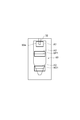
- a hardware configuration of the controller 100 for example, a circuit having a processor 101, a memory 102, a storage 103, an input / output port 104, and a driver 105 can be cited as shown in FIG.
- the driver 105 is a circuit for controlling the actuator of the robot 10.
- the input / output port 104 inputs / outputs data between the camera 40 and the console 70, outputs a suction or discharge on / off command to the dispenser 30, and sends a drive command for the actuator of the robot 10 to the driver 105. Output.
- the processor 101 configures each function of the controller 100 described above by executing a program in cooperation with at least one of the memory 102 and the storage 103.
- the camera 40, the console 70, and the controller 100 may be integrated on hardware or may be separated from each other.
- the controller 100 may be divided into a plurality of hardware.
- the separated hardware may be connected by either wire or wireless, and there is no limitation on the connection method.
- the circuit of the controller 100 acquires the position information of the liquid level SF1, the position information of the boundary portion BD1, and the position information of the tip portion 30a based on the image captured by the camera 40, and the liquid C1. Is sucked into the dispenser 30, the robot 10 is caused to lower the dispenser 30 based on the position information of the tip 30 a, the position information of the liquid level SF 1, and the position information of the boundary BD 1. Is configured to perform the control.
- the hardware configuration of the controller 100 is not necessarily limited to that configuring each functional module by executing a program.
- the controller 100 may constitute each function by a dedicated logic circuit or an ASIC (Application Specific Integrated Circuit) in which the controller 100 is integrated.
- ASIC Application Specific Integrated Circuit
- Protocol Construction Procedure (1) Overall Configuration Next, a protocol construction procedure by the controller 100 will be described as an example of a protocol construction method.
- step S101 the process setting unit 111 sets a work process of the robot 10 including a plurality of types of dispensing work.
- the process setting unit 111 acquires a work process of the robot 10 including a plurality of types of dispensing work from the console 70 and registers it in the process storage unit 151.
- FIG. 9 is a diagram illustrating an example of setting work processes.
- This work process includes steps S01 to S23.
- Step S01 is a step of injecting the first reagent into the first container 80 containing a sample such as a cell, and stirring the contents of the container 80 using, for example, a vortex mixer.
- Step S02 is a process of separating the contents of the first container 80 into the liquid C1 to be dispensed and the non-dispensing object C2 by centrifugation or the like.
- Step S03 is a step of taking out the liquid C1 to be dispensed in the first container 80 and transferring it to the second container 80.
- Step S11 is a process of injecting the second reagent into the second container 80 containing the liquid C1, and stirring the contents of the container 80 by, for example, a vortex mixer.
- Step S12 is a step of separating the contents of the second container 80 into the liquid C1 to be dispensed and the non-dispensing object C2 by centrifugation or the like.
- Step S13 is a step of discharging the liquid C1 to be dispensed in the second container 80.
- Step S21 is a step of injecting the third reagent into the second container 80 containing the remaining non-dispensing object C2, and stirring the contents of the container 80 by, for example, a vortex mixer.
- Step S22 is a step of separating the contents of the second container 80 into the liquid C1 to be dispensed and the non-dispensing object C2 by centrifugation or the like.
- Step S ⁇ b> 23 is a step of discharging the liquid C ⁇ b> 1 to be dispensed in the second container 80 and collecting the non-dispensing object C ⁇ b> 2 remaining in the container 80.
- steps S03, S13, and S23 correspond to the dispensing work.
- step S102 the robot control unit 130 controls the robot 10 to start execution of the process set in step S101.
- the robot control unit 130 executes step S102 in response to, for example, a command input by the user.
- step S103 the process confirmation unit 114 confirms whether or not the process to be executed is a dispensing operation.
- the controller 100 executes step S114.
- step S114 the robot control unit 130 controls the robot 10 to execute the process.
- step S115 the controller 100 proceeds with the process to step S115 described later.
- step S ⁇ b> 104 the robot control unit 130 controls the arm 13 ⁇ / b> B so that the container 80 is disposed on the container holding unit 62.
- the robot control unit 130 controls the arm 13B so as to remove the cap.
- step S105 the robot control unit 130 controls the arm 13A so as to start conveyance of the dispenser 30 to the container 80 side.
- step S106 the controller 100 executes step S106.
- step S ⁇ b> 106 the interrupt unit 112 checks whether or not the reference data for the dispensing work to be executed is registered in the reference data storage unit 152. If it is determined that the reference data is registered, the controller 100 advances the process to step S112 described later.
- step S ⁇ b> 107 the interrupt unit 112 acquires an image from the camera 40.
- step S108 based on the image acquired in step S107, the interrupt unit 112 determines whether or not the distal end portion 30a has reached the reference data registration position.
- the reference data registration position means a position that falls within the field of view of the camera 40 above the liquid level SF1.
- the interrupt unit 112 repeats steps S107 and S108 until the tip 30a reaches the reference data registration position.
- step S109 If it is determined in step S108 that the tip 30a has reached the reference data registration position, the controller 100 executes step S109.
- step S ⁇ b> 109 the interrupt unit 112 outputs a command to stop the transport of the dispenser 30 to the robot control unit 130.
- the robot control unit 130 controls the robot 10 to stop the transport of the dispenser 30 in response to a command from the interrupt unit 112.
- the interrupt unit 112 stops the robot 10 after the tip 30a enters the field of view of the camera 40 when the reference data is not registered.
- step S110 the reference data registration unit 113 performs registration of reference data.
- step S ⁇ b> 111 the interrupt unit 112 outputs a command for resuming conveyance of the dispenser 30 to the robot control unit 130.
- the robot control unit 130 controls the robot 10 so as to resume conveyance of the dispenser 30 in response to a command from the interrupt unit 112.
- the reference data registration unit 113 performs registration of the reference data when the interrupt unit 112 stops the robot 10, and the interrupt unit 112 resumes the operation of the robot 10 after the registration of the reference data.
- step S112 the robot control unit 130 controls the arm 13A so as to place the dispenser 30 at the suction start position.
- the starting position of the suction is set in advance at a position having a predetermined depth from the liquid level SF1, for example.
- step S113 the robot controller 130 and the dispenser controller 140 respectively control the robot 10 and the dispenser 30 so as to execute the dispensing operation.
- step S115 the robot control unit 130 determines whether or not the execution of all processes has been completed. When it is determined that the execution of all the processes has not been completed, the controller 100 executes Step S116. In step S116, the reference data registration unit 113 shifts the execution target to the next step. Thereafter, the controller 100 returns the process to step S103. Thereby, stopping the robot 10 when the reference data is not registered is executed by the interrupt unit 112 for each dispensing operation. Each time the interrupt unit 112 stops the robot 10, the reference data registration unit 113 executes registration of reference data corresponding to the dispensing operation scheduled to be executed next.
- step S115 If it is determined in step S115 that the execution of all processes has been completed, the controller 100 ends the process. This completes the protocol construction procedure.
- step S ⁇ b> 201 the backlight control unit 125 turns on the backlight 50, and the reference data registration unit 113 displays a reference data setting screen on the monitor 71 of the console 70.
- step S202 the reference data registration unit 113 acquires a first analysis region for searching the tip 30a outside the liquid C1 in the image from the console 70, and registers this as reference data in the reference data storage unit 152. To do.
- step S203 the reference data registration unit 113 acquires a second analysis region for searching for the liquid level SF1 in the image from the console 70, and registers this as reference data in the reference data storage unit 152.
- step S204 the reference data registration unit 113 acquires a third analysis region for searching the boundary portion BD1 in the image from the console 70, and registers this as reference data in the reference data storage unit 152.
- the execution order of steps S202 to S204 can be changed as appropriate.
- the reference data registration unit 113 may sequentially execute acquisition of the second analysis region, acquisition of the third analysis region, and acquisition of the first analysis region.
- FIG. 11 is a diagram illustrating an analysis area setting screen. This screen displays the image captured by the camera 40 and the analysis region input to the input device 72 by the user in an overlapping manner.
- An analysis area A1 in FIG. 11 indicates an area input for setting the first analysis area.
- the analysis region A1 is set so as to include the tip portion 30a outside the liquid C1.
- the analysis area A2 indicates an area input for setting the second analysis area.
- the analysis region A2 is set so as to include the liquid level SF1.
- the analysis area A3 indicates an area input for setting the third analysis area.
- the analysis region A3 is set so as to include the boundary portion BD1.
- the reference data registration unit 113 registers the analysis region A1 as the first analysis region in the reference data storage unit 152, registers the analysis region A2 as the second analysis region in the reference data storage unit 152, and sets the analysis region A3 as the first analysis region.
- the third analysis area is registered in the reference data storage unit 152.
- step S205 the reference data registration unit 113 acquires the image pattern of the tip portion 30a and registers it in the reference data storage unit 152 as reference data.
- FIG. 12 is a diagram illustrating an image pattern registration screen.
- This screen displays an image in the vicinity of the distal end portion 30a and a frame line P1 input to the input device 72 by the user in an overlapping manner.
- This screen may be an enlarged display of the analysis area A1 in FIG.
- a frame line P1 designates an area to be used as an image pattern.
- the reference data registration unit 113 registers the image of the area surrounded by the frame line P1 in the reference data storage unit 152 as an image pattern of the tip portion 30a.
- step S ⁇ b> 206 the reference data registration unit 113 outputs a command to insert the tip portion 30 a into the liquid C ⁇ b> 1 to the robot control unit 130.
- the robot control unit 130 controls the robot 10 to lower the dispenser 30 and insert the tip 30a into the liquid C1.
- Step S207 the reference data registration unit 113 acquires the image pattern of the tip portion 30a as in step S205, and registers this as reference data in the reference data storage unit 152. As described above, the reference data registration unit 113 registers the image pattern of the tip 30a outside the liquid C1 and the image pattern of the tip 30a in the liquid C1 as reference data. Thereafter, the backlight control unit 125 turns off the backlight 50.
- reference data registration unit 113 illustrated the case where the first analysis region, the second analysis region, the third analysis region, and the image pattern of the tip 30a inside and outside the liquid C1 are registered as reference data, It is not limited to this.
- the reference data registration unit 113 may register only a part of the reference data exemplified above.
- the reference data may be any data as long as it is necessary for the control of the robot 10. Therefore, the reference data registration unit 113 may register reference data different from those exemplified above. Good.
- Dispensing Control Execution Procedure (1) Overall Configuration Next, a dispensing control procedure executed by the controller 100 will be described as an example of a control method.
- FIG. 13 shows a control procedure when the liquid C1 in the container 80 is transferred to another container 80 as an example of the dispensing operation.
- the controller 100 first executes step S301.
- step S ⁇ b> 301 the container arrangement control unit 131 controls the arm 13 ⁇ / b> B so that the container 80 is arranged on the container holding unit 62.
- the container arrangement control unit 131 controls the arm 13B so as to remove the cap.
- step S302 the robot control unit 130 controls the arm 13A so as to place the distal end portion 30a of the dispenser 30 at a position for image acquisition.
- the image acquisition position means a position that falls within the field of view of the camera 40 above the liquid level SF1.
- the backlight control unit 125 turns on the backlight 50, and the image processing unit 120 acquires an image from the camera 40.
- This image includes at least the tip 30a, a part of the liquid level SF1, and a part of the non-dispensing object C2.
- step S303 the image processing unit 120 acquires the position information of the liquid surface SF1 and the position information of the tip 30a based on the image acquired in step S302.
- the image processing unit 120 acquires information on the second analysis region from the reference data storage unit 152, and acquires position information on the liquid level SF1 from within the second analysis region.
- the image processing unit 120 detects a linear portion passing through the second analysis region, and acquires the position as position information of the liquid surface SF1.
- the image processing unit 120 acquires the first analysis region information and the image pattern of the tip 30a outside the liquid C1 from the reference data storage unit 152, and based on the image pattern, the position information of the tip 30a is first. Obtain from within the analysis area.
- the image processing unit 120 acquires the position of a portion that matches the image pattern of the tip portion 30a as position information of the tip portion 30a in the first analysis region.
- the image processing unit 120 may further acquire position information of the boundary part BD1.
- the image processing unit 120 acquires information on the third analysis region from the reference data storage unit 152, and acquires position information on the boundary portion BD1 from within the third analysis region.
- the image processing unit 120 detects a linear portion passing through the third analysis region, and acquires the position as position information of the boundary portion BD1.
- step S304 the dispenser arrangement control unit 132 controls the arm 13A so that the distal end 30a is arranged at the suction start position OP1 (see FIG. 16A). Specifically, the dispenser arrangement control unit 132 moves based on the position information of the tip part 30a and the position information of the liquid level SF1 acquired in step S303 to move the tip part 30a at the start position OP1. Is calculated, and the arm 13A is controlled to move the tip 30a by the amount of movement.
- the start position OP1 is set in advance to a position at a predetermined depth (hereinafter referred to as “reference depth”) DP1 from the liquid level SF1.
- the reference depth DP1 is set in advance so as to satisfy the following conditions, for example.
- Condition 1-1) The depth is small compared to the depth from the liquid level SF1 to the boundary portion BD1.
- Condition 1-2) The tip 30a can be maintained in the liquid C1 even if a position control error occurs.
- step S305 the dispenser control unit 140 and the descent control unit 133 control the dispenser 30 and the robot 10 so as to perform the suction of the liquid C1.
- the dispenser controller 140 controls the dispenser controller 140 so that the liquid C1 is sucked from the container 80.
- the descent controller 133 sucks the liquid into the dispenser 30
- the dispenser 30 is based on the position information on the tip 30a, the position information on the liquid surface SF1, and the position information on the boundary BD1.
- the robot 10 is controlled to move down.
- the backlight control unit 125 turns off the backlight 50.
- step S306 the dispenser arrangement control unit 132 controls the arm 13A so as to pull out the tip 30a from the container 80.
- step S307 the container arrangement control unit 131 controls the arm 13B so as to replace the container 80 of the container holding unit 62 with another container 80.
- step S308 the dispenser arrangement control unit 132 controls the arm 13A so as to arrange the tip part 30a at the discharge start position.
- the discharge start position is set in advance to a position in the container 80.
- step S309 the dispenser controller 140 controls the dispenser controller 140 so that the liquid C1 is discharged into the container 80.
- step S ⁇ b> 310 the dispenser arrangement control unit 132 controls the arm 13 ⁇ / b> A so that the distal end portion 30 a is pulled out from the container 80. This completes the dispensing operation.
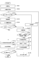
- step S401 the dispenser control unit 140 controls the dispenser 30 so as to start suction of the liquid C1 in the container 80.
- step S ⁇ b> 402 the image processing unit 120 acquires an image from the camera 40.
- This image includes at least the tip 30a, a part of the liquid level SF1, and a part of the non-dispensing object C2.
- step S403 the image processing unit 120 acquires the position information of the liquid surface SF1, the position information of the boundary portion BD1, and the position information of the tip portion 30a based on the image acquired in step S402.
- the image processing unit 120 acquires information on the second analysis region from the reference data storage unit 152, and acquires position information on the liquid level SF1 from within the second analysis region.
- the image processing unit 120 detects a linear portion passing through the second analysis region, and acquires the position as position information of the liquid surface SF1.
- the image processing unit 120 acquires information on the third analysis region from the reference data storage unit 152, and acquires position information on the boundary portion BD1 from within the third analysis region.
- the image processing unit 120 detects a linear portion passing through the third analysis region, and acquires the position as position information of the boundary portion BD1.
- the image processing unit 120 acquires the image pattern of the tip 30a in the liquid C1 from the reference data storage unit 152, and based on the image pattern of the tip 30a, the position information of the tip 30a from the second analysis region. get.
- the image processing unit 120 acquires the position of a portion that matches the image pattern of the tip portion 30a as position information of the tip portion 30a in the second analysis region.
- step S404 the inclination detection unit 137 detects the inclination of the boundary part BD1 based on the image acquired in step S402.
- the inclination detection unit 137 may detect the inclination of the boundary part BD1 based on the position information of the boundary part BD1 acquired by the image processing unit 120.
- step S405 the target position setting unit 136 sets the final target position GL1 (see FIG. 16B) based on the position information of the boundary part BD1 acquired in step S403.
- the target position setting unit 136 sets the final target position GL1 above the position of the boundary part BD1.
- the target position setting unit 136 sets the final target position GL1 so that the distance between the final target position GL1 and the boundary part BD1 in the vertical direction becomes a predetermined vertical offset value VO1.
- the vertical offset value VO1 is set in advance so as to satisfy the following condition, for example.
- Condition 2-1) The depth is small compared to the depth from the liquid level SF1 to the boundary portion BD1.
- Condition 2-2) The tip 30a does not reach the boundary BD1 even if a position control error occurs.
- the target position setting unit 136 uses the center position of the container 80 (for example, the central axis CL1 of the side wall 81) as a reference.
- the position shifted in the direction of decreasing the inclination of BD1 is set as the final target position GL1 (see FIG. 17B).
- the target position setting unit 136 sets the final target position GL1 so that the horizontal distance between the final target position GL1 and the central axis CL1 of the container 80 becomes a predetermined horizontal offset value HO1.
- the horizontal offset value HO1 is set in advance so as to satisfy the following condition, for example.
- the dispenser 30 does not interfere with the side wall 81 of the container 80. Also in this case, the target position setting unit 136 sets the final target position GL1 so that the distance between the final target position GL1 and the boundary portion BD1 in the vertical direction becomes the predetermined vertical offset value VO2.
- the vertical offset value VO2 is also set in advance so as to satisfy the same condition as the vertical offset value VO1.
- step S406 the image processing unit 120 acquires an image from the camera 40 as in step S402.
- step S407 the image processing unit 120 acquires the position information of the liquid surface SF1, the position information of the boundary part BD1, and the position information of the tip part 30a, as in step S403.
- step S408 the inclination detection unit 137 detects the inclination of the boundary part BD1 as in step S404.
- the first mode control unit 133a controls the robot 10 so as to lower the tip portion 30a following the lowering of the liquid level SF1 by lowering the dispenser 30 by the arm 13A (hereinafter, referred to as “the first mode control unit 133a”). This control is referred to as “first mode lowering control”).
- the first mode control unit 133a performs the first mode lowering control based on the position information of the liquid level SF1 and the position information of the tip part 30a. Specifically, the first mode control unit 133a executes the first mode lowering control so that the depth from the liquid level SF1 to the tip 30a is maintained at a value close to the reference depth DP1 (FIG. 16 ( b)).
- the reference distance setting unit 134 sets the reference distance RF1 (see FIG. 16B).
- the reference distance setting unit 134 may be configured to increase the reference distance RF1 as the moving speed of the distal end portion 30a increases.
- the reference distance setting unit 134 may be configured to set the reference distance RF1 to a value proportional to the descending speed of the distal end portion 30a.
- the descending speed of the tip portion 30a can be calculated based on, for example, the difference between the position information of the tip portion 30a acquired this time and the position information of the tip portion 30a acquired last time. It is also possible to calculate the descending speed based on the average value of the differences calculated over a plurality of times.
- step S411 the boundary monitoring unit 135 determines whether or not the boundary part BD1 has changed based on the position information of the boundary part BD1 acquired in step S407. If no change is detected at the boundary in step S411, the controller 100 advances the process to step S413.
- step S412 the target position setting unit 136 sets the final target position GL1 in the same manner as in step S405, based on the position information of the boundary part BD1 acquired in step S407. That is, the target position setting unit 136 updates the final target position GL1 based on the position information of the boundary part BD1 when the robot 10 moves the dispenser 30 downward. Further, the target position setting unit 136 updates the final target position GL1 when the boundary monitoring unit 135 detects a change in the boundary part BD1.
- step S413 the switching unit 133c determines whether the distance from the tip 30a to the final target position GL1 (hereinafter referred to as “first remaining distance”) LD1 is smaller than the reference distance RF1 set in advance in step S410. Determine whether or not.
- first remaining distance the distance from the tip 30a to the final target position GL1 (hereinafter referred to as “first remaining distance”) LD1 is smaller than the reference distance RF1 set in advance in step S410. Determine whether or not.
- the controller 100 returns the process to step S405. Thereby, the control by the first mode control unit 133a is continued.
- step S414 the switching unit 133c switches the control by the first mode control unit 133a to the control by the second mode control unit 133b.
- step S413 and S414 the switching unit 133c switches the control by the first mode control unit 133a to the control by the second mode control unit 133b in response to the leading end 30a approaching the final target position GL1. .
- step S415 the image processing unit 120 acquires an image from the camera 40 as in step S402.
- step S416 the image processing unit 120 acquires the position information of the liquid level SF1, the position information of the boundary part BD1, and the position information of the tip part 30a as in step S403.
- step S417 the inclination detection unit 137 further detects the inclination of the boundary part BD1 as in step S404.
- step S4108 the second mode control unit 133b controls the robot 10 so that the tip 30a is brought close to the final target position GL1 by lowering the dispenser 30 with the arm 13A (hereinafter, this control is referred to as “first control”). "Two-mode descent control").
- the second mode control unit 133b may perform control to suppress overshooting as compared to the first mode control unit 133a.
- the first mode control unit 133a may perform control to increase responsiveness compared to the second mode control unit 133b.
- feedforward control that compensates for delay in image processing is performed, and in the control by the second mode control unit 133b, the feedforward control is not performed. Is mentioned.
- the control by the first mode control unit 133a there is a configuration in which the gain for the deviation is set higher than the control by the second mode control unit 133b.
- Step S419 the controller 100 executes Step S419 similar to Step S411.
- the boundary monitoring unit 135 determines whether there is a change in the boundary part BD1 based on the position information of the boundary part BD1 acquired in step S416. If no change is detected in the boundary portion BD1 in step S419, the controller 100 advances the process to step S421.
- Step S419 when a change is detected in the boundary portion BD1, the controller 100 executes Step S420 similar to Step S412.
- the target position setting unit 136 updates the final target position GL1 based on the position information of the boundary part BD1 acquired in step S416.
- Step S421 the second mode control unit 133b detects whether or not the first remaining distance LD1 is equal to or less than zero. When it is determined that the first remaining distance LD1 is greater than zero (see FIG. 16C), the controller 100 returns the process to step S415. Thereby, the control by the second mode control unit 133b is continued.
- Step S422 the controller 100 executes Step S422.
- the second mode control unit 133b controls the robot 10 to stop the lowering of the dispenser 30.
- the descent control of the dispenser 30 by the descent control unit 133 is completed.
- the lowering control unit 133 controls the robot 10 to lower the tip 30a to the final target position GL1 by lowering the tip 30a following the lowering of the liquid level SF1. To do.
- step S423 the dispenser control unit 140 controls the dispenser 30 so as to stop the suction of the liquid C1 (see FIG. 16 (e)). Thereafter, the backlight control unit 125 turns off the backlight 50. This completes the suction procedure.
- the controller 100 is configured so that the boundary BD1 can be inclined with respect to the liquid level SF1 (for example, when the boundary BD1 is inclined with respect to the central axis CL1 of the container 80).
- the suction procedure of step S305 may be executed in a state where the container 80 is tilted in a direction in which the boundary portion BD1 is gently inclined with respect to the liquid level SF1.
- the lowering control unit 133 controls the robot 10 so as to lower the distal end portion 30a of the dispenser 30 in an oblique direction corresponding to the inclination of the container 80 (FIGS. 19A to 19). d)).
- Lowering the distal end portion 30 a in an oblique direction corresponding to the inclination of the container 80 means lowering the distal end portion 30 a so as not to contact the side wall 81 of the container 80.
- the lowering control unit 133 may control the robot 10 so as to lower the distal end portion 30a along the inclined central axis CL1 of the container 80.
- the controller 100 sets, as the final target position GL1, a position shifted in the direction of decreasing the inclination of the boundary portion BD1 with respect to the central axis CL1 of the container 80, and gently reduces the inclination of the boundary portion BD1 with respect to the liquid surface SF1. It may be configured to perform only one of making the container 80 tilted in the direction to be performed, or may be configured to perform both of these in combination.
- the container placement control unit 131 controls the robot 10 so as to place the container 80 on the container holding unit 62
- the tilt control unit 138 controls the robot 10 so that the container 80 is tilted by tilting the rack 60. Also good.
- the container placement control unit 131 may control the robot 10 so that the container 80 is placed on the container holding unit 62.
- the container 80 may be disposed so as to be inclined in a direction in which the inclination of the boundary portion BD1 with respect to the liquid surface SF1 becomes gentle before being transported from outside the field of view of the camera 40 into the field of view.
- the container placement control unit 131 may control the robot 10 so that the container 80 is transported from outside the field of view of the camera 40 and placed on the container holding unit 62 while maintaining the tilt of the container 80. Good.
- the controller 100 uses the stopper 67 to maintain the inclination of the rack 60 constant.
- the robot 10 may be controlled so as to maintain the above. For example, the controller 100 raises the upper portion 65a of the handle 65 with the arm 13B and tilts the support plate 61A, and the arm 13A tilts the stopper 67 toward the hinge 66 and fits the edge of the support plate 61A into the groove portion 67b.
- the robot 10 may be controlled so as to be included (see FIG. 20).
- the edge of the support plate 61A is fitted into the groove 67b, the inclination of the rack 60 is maintained by the stopper 67, so that the handle 65 and the stopper 67 can be released from the arms 13A and 13B.
- the arm 13A it is possible to cause the arm 13A to perform the operation of arranging the dispenser 30 at the position for image acquisition.
- the upper portion of the container 80 is closed with a cap, it is possible to cause the arm 13B to perform the operation of removing the cap.
- the dispenser 30 is a manual type, the dispenser 30 can be operated by cooperation of the arms 13A and 13B.
- the stopper 67 the arms 13A and 13B can be used for a wider range of work.
- the controller 100 may execute in the middle of step S305 that the container 80 is tilted in a direction in which the boundary of the boundary portion BD1 with respect to the liquid level SF1 becomes gentle.
- the tilt control unit 138 may control the robot 10 so that the container 80 is tilted by tilting the rack 60 while the robot 10 is lowering the distal end portion 30a (hereinafter referred to as “tilt control”). Called).
- the tilt control unit 138 may control the robot 10 so that the container 80 is tilted in accordance with the leading end 30a approaching the final target position GL1.
- FIG. 18 is a flowchart illustrating the tilt control procedure.
- the controller 100 first executes step S501.
- step S501 the tilt control unit 138 determines the distance from the liquid level SF1 to the boundary part BD1 (hereinafter referred to as “second remaining distance”) based on the position information acquired in any of steps S403, S406, and S414. .) Wait until LD2 becomes smaller than the reference distance RF3 (see FIGS. 21A and 21B).
- the reference distance RF3 is set in advance so that the tilting of the container 80 and the dispenser 30 is started before the liquid level SF1 reaches the boundary BD1.
- step S502 the controller 100 executes steps S502 to S506.
- the inclination detection unit 137 detects the inclination angle ⁇ of the boundary part BD1 with respect to the liquid level SF1 based on the image acquired in any of steps S402, S405, and S413 (see FIG. 21C).
- the inclination angle ⁇ can be calculated, for example, by complementing the shape of the boundary portion BD1 with the wire diameter.
- step S503 the tilt control unit 138 sets a target tilt angle RF5 corresponding to the tilt angle ⁇ .
- the tilt control unit 138 sets the target tilt angle RF5 to a value equal to the tilt angle ⁇ .
- step S504 the tilt control unit 138 controls the robot 10 to start tilting the container 80 and the dispenser 30 (see FIGS. 21D and 21E).
- the tilt control unit 138 controls the robot 10 to tilt the container 80 by tilting the rack 60 by raising the upper portion 65a of the handle 65 by the arm 13B (see FIG. 22).
- the rack 60 tilts around an axis along the direction in which the camera 40, the container 80, and the backlight 50 are arranged.
- the tilt control unit 138 controls the robot 10 so that the dispenser 30 is tilted by the arm 13A in accordance with the tilt of the container 80.
- step S505 the tilt control unit 138 waits for the tilt angle of the container 80 and the dispenser 30 to be equal to or greater than the target tilt angle RF5.
- step S506 the tilt control unit 138 controls the robot 10 so as to stop the tilt of the container 80 and the dispenser 30.
- the tilt angle ⁇ is determined substantially uniformly depending on the characteristics of the centrifuge and may be handled as a constant. In such a case, step S502 for detecting the tilt angle ⁇ may be omitted. 4). Effects of this embodiment
- the dispensing system 1 includes the robot 10 that moves the dispenser 30 for sucking the liquid C1 to be dispensed, the tip 30a of the dispenser 30, and the liquid C1.
- the camera 40 for capturing an image including the liquid level SF1 and the non-dispensing object C2 positioned below the liquid level SF1, the position information of the liquid level SF1, and the liquid C1 based on the image.
- the image processing unit 120 that acquires the position information of the boundary portion BD1 between the non-dispensing object C2 and the position information of the tip portion 30a of the dispenser 30 and the liquid C1 are sucked into the dispenser 30.
- a lowering control unit 133 that controls the robot 10 to lower the dispenser 30; Is provided.
- this dispensing system 1 it is possible to keep the tip 30a at a shallow position from the liquid surface SF1 by lowering the tip 30a based on the positional relationship between the liquid level SF1 and the tip 30a. Thereby, the liquid adhering to the outer periphery of the front-end
- tip part 30a is reduced.
- the tip portion 30a By lowering the tip portion 30a based on the positional relationship between the boundary portion BD1 and the tip portion 30a, the tip portion 30a can be brought closer to the boundary portion BD1. Thereby, the liquid C1 is sufficiently sucked.
- the tip portion 30a can be maintained in the liquid, and the occurrence of idle suction (gas suction) can be suppressed. Therefore, more reliable dispensing work can be executed.
- the position information of the tip 30a, the position information of the liquid surface SF1, and the position information of the boundary part BD1 are acquired for each dispensing operation based on the image information. Since the position information of the liquid surface SF1 and the position information of the boundary portion BD1 are likely to vary, a more reliable dispensing operation can be executed by acquiring these pieces of information for each dispensing operation.
- the chip 32 is detachable from the main body 31, the position of the tip 30 a relative to the main body 31 is likely to vary. For this reason, the effect of acquiring the positional information on the tip portion 30a, the positional information on the liquid level SF1, and the positional information on the boundary portion BD1 for each dispensing operation becomes more remarkable.
- the dispensing system 1 may further include a target position setting unit 136 that sets the final target position GL1 based on the position information of the boundary BD1, and the lowering control unit 133 follows the lowering of the liquid level SF1.
- the robot 10 may be controlled such that the tip 30a of the dispenser 30 is lowered and the tip 30a of the dispenser 30 is lowered to the final target position GL1.
- the tip part 30a can be more reliably maintained at a shallow position from the liquid level SF1.
- the tip part 30a can be brought closer to the boundary part BD1 more reliably. Therefore, more reliable dispensing work can be executed.
- the dispensing system 1 only needs to lower the dispenser 30 based on the position information of the tip portion 30a, the position information of the liquid level SF1, and the position information of the boundary portion BD1, so that the target It is not essential to further include the position setting unit 136, to lower the tip part 30a following the lowering of the liquid level SF1, and to lower the tip part 30a to the final target position GL1.
- the target position setting unit 136 may update the final target position GL1 based on the position information of the boundary part BD1 when the robot 10 lowers the dispenser 30. In this case, since the final target position GL1 can be updated according to the movement of the boundary portion BD1 even when the position of the boundary portion BD1 varies, the tip portion 30a can be brought closer to the boundary portion BD1 more reliably. It becomes possible. Therefore, more reliable dispensing work can be executed. However, it is not essential to update the final target position GL1 by the target position setting unit 136.
- the dispensing system 1 may further include a boundary monitoring unit 135 that detects a change in the boundary part BD1 based on the image, and the target position setting unit 136 detects a change in the boundary part BD1 by the boundary monitoring unit 135.
- the final target position GL1 may be updated based on the position information of the boundary portion BD1.
- the calculation load can be reduced by updating the final target position GL1 only when a change is detected in the boundary portion BD1.
- the target position setting unit 136 may be configured to update the final target position GL1 every time the position information of the boundary part BD1 is acquired.
- the lowering control unit 133 includes a first mode control unit 133a that controls the robot 10 to lower the tip part 30a of the dispenser 30 following the lowering of the liquid level SF1, and a tip part 30a of the dispenser 30.
- the second mode control unit 133b that controls the robot 10 to move down to the final target position GL1, and the control by the first mode control unit 133a as the tip 30a of the dispenser 30 approaches the final target position GL1.
- a switching unit 133c that switches to control by the second mode control unit 133b.
- priority is given to following the liquid level SF1, so that the tip 30a can be more reliably kept at a shallow position from the liquid level SF1.
- the first mode control unit 133a performs control to increase responsiveness compared to the second mode control unit 133b
- the second mode control unit 133b performs control to suppress overshoot compared to the first mode control unit 133a. May be.
- the delay of the tip 30a with respect to the lowering of the liquid level SF1 is reduced, so that the position of the tip 30a can be kept at a shallower position from the liquid level SF1.
- the second mode control unit 133b the amount of overshoot with respect to the final target position GL1 is reduced, so that the tip 30a can be brought closer to the boundary BD1 more reliably. Therefore, more reliable dispensing work can be executed.
- the switching unit 133c may switch the control by the first mode control unit 133a to the control by the second mode control unit 133b as the remaining distance LD1 becomes smaller than the preset reference distance RF1. In this case, switching from the first mode control unit 133a to the second mode control unit 133b can be more reliably performed by simplifying the determination criterion.
- the criterion for switching is not limited to this.
- the dispensing system 1 may further include a reference distance setting unit 134 that increases the reference distance RF1 as the moving speed of the tip 30a of the dispenser 30 increases.
- a reference distance setting unit 134 that increases the reference distance RF1 as the moving speed of the tip 30a of the dispenser 30 increases.
- the descending control unit 133 is configured so that the tip of the dispenser 30 corresponds to the inclination of the container 80 in a state where the liquid C1 and the non-dispensing object C2 are accommodated in the inclined container 80 in the field of view of the camera 40.
- the robot 10 may be controlled so that 30a is lowered in an oblique direction. In this case, it is possible to perform the suction of the liquid C1 in a state where the container 80 is inclined so that the inclination of the boundary portion BD1 with respect to the liquid level SF1 is gentle as compared with the case where the container 80 is upright.
- the dispensing system 1 conveys the container 80 from the outside of the field of view of the camera 40 while maintaining the state where the container 80 is inclined in a direction in which the inclination of the boundary BD1 with respect to the liquid level SF1 is moderated. You may further provide the container arrangement
- a tilt control unit 138 for controlling the robot 10 so as to tilt the container 80 in a direction in which the tilt of the boundary part BD1 with respect to the liquid level SF1 may be further provided.
- the container 80 can be tilted according to the state of the boundary portion BD1.
- the dispensing system 1 further includes an inclination detection unit 137 that detects the inclination of the boundary part BD1 with respect to the liquid surface SF1 based on the image, and the tilt control unit 138 detects the inclination of the boundary part BD1 by the inclination detection unit 137.
- the robot 80 tilts the container 80 and the dispenser 30 in a direction in which the inclination of the boundary BD1 becomes gentle as the tip 30a of the dispenser 30 approaches the final target position GL1. 10 may be controlled.
- the container 80 is tilted after the liquid C1 in the container 80 is reduced by suction, the leakage of the liquid C1 due to the tilting of the container 80 can be prevented more reliably.
- the tilt control unit 138 may control the robot 10 to tilt the container 80 and the dispenser 30 before the liquid level SF1 reaches the boundary BD1. In this case, the fluctuation of the boundary portion BD1 is more reliably suppressed. Thereby, since the position of the final target position GL1 is further stabilized, the tip portion 30a can be brought closer to the boundary portion BD1 more reliably.
- the dispensing system 1 may include a double-armed robot 10 having first and second arms 13A and 13B.
- the lowering control unit 133 controls the robot 10 so as to lower the dispenser 30 by the first arm 13A, and the tilt control unit 138 tilts the dispenser 30 by the first arm 13A, and the second arm
- the robot 10 may be controlled so that the container 80 is tilted by 13B.
- the two-arm robot 10 can be effectively used, and the suction procedure involving the tilting of the container 80 and the dispenser 30 can be made efficient.
- the robot 10 is of the double arm type.
- the dispensing system 1 may include a device that tilts the container 80 separately from the robot 10.
- the tilt detector 137 may detect the tilt angle ⁇ of the boundary BD1 with respect to the liquid level SF1 based on the image.
- the tilt control unit 138 may control the robot 10 to tilt the container 80 and the dispenser 30 at the target tilt angle RF5 corresponding to the tilt angle ⁇ .
- the fluctuation of the boundary portion BD1 is more reliably suppressed.
- the tip 30a can be brought closer to the boundary BD1 more reliably. Therefore, more reliable dispensing work can be executed.
- the target position setting unit 136 sets the position shifted in the direction of decreasing the inclination of the boundary part BD1 with respect to the center position of the container 80 as the final target. You may set as position GL1. In this case, the tip portion 30a can be advanced to a deeper position in the container 80, and more liquid C1 can be sucked (see FIGS. 17B to 17E). Therefore, more reliable dispensing work can be executed. However, it is not indispensable to set the position shifted in the direction in which the boundary portion BD1 is inclined downward with respect to the center position as the final target position GL1.
- the dispensing system 1 may further include a rack 60 that holds both the camera 40 and the container 80.
- the lowering control unit 133 may control the robot 10 to lower the distal end portion 30a of the dispenser 30 in an oblique direction in a state where the inclination of the container 80 is maintained by the rack 60.
- the container 80 is more reliably maintained within the field of view of the camera 40 even when the container 80 is tilted.
- the distance between the camera 40 and the container 80 is stabilized, blurring of the image is suppressed. Therefore, since the acquisition of various position information based on the image can be more reliably executed, a more reliable dispensing operation can be executed. However, it is not essential to provide the rack 60.
- the dispensing system 1 may further include a rack 60 that holds both the camera 40 and the container 80.
- the tilt control unit 138 may control the robot 10 so that the container 80 is tilted by tilting the rack 60.
- the container 80 is more reliably kept within the field of view of the camera 40.
- the distance between the camera 40 and the container 80 is stabilized, blurring of the image is suppressed. Therefore, since the acquisition of various position information based on the image can be more reliably executed, a more reliable dispensing operation can be executed. However, it is not essential to provide the rack 60.
- the dispensing system 1 may further include a backlight 50 that irradiates the container 80 with light.
- the backlight 50 may be held on the rack 60 together with the camera 40 and the container 80 in an arrangement in which the container 80 is sandwiched between the backlight 40 and the camera 40.
- the backlight 50 since the backlight 50 is also tilted together with the container 80, acquisition of various position information based on the image can be more reliably performed. Therefore, more reliable dispensing work can be executed. However, it is not essential to provide the backlight 50.
- the backlight 50 may emit red visible light. In this case, the detection sensitivity of the liquid level SF1 and the boundary portion BD1 in image processing can be increased.
- a backlight control unit 125 that turns off the backlight 50 in at least a part of the time zone when the camera 40 is not capturing an image may be further provided. In this case, the lighting time of the backlight 50 can be reduced and the burden on the operator's eyes can be reduced.
- the dispensing system 1 includes a console 70 for registering reference data for dispensing work performed by the robot 10, and the tip 30a of the dispenser 30 within the field of view of the camera 40 when the reference data is not registered.
- An interrupt unit 112 for stopping the robot 10 after entering and restarting the operation of the robot 10 after registration of the reference data, and a screen for setting reference data when the interrupt unit 112 stops the robot 10 May be further provided on the console 70, and a reference data registration unit 113 for acquiring and registering reference data from the console 70.
- the operation of the robot 10 is temporarily interrupted by the interrupt unit 112, and the reference data registration unit 113.
- the dispensing system 1 may further include a process setting unit 111 that sets a work process of the robot 10 including a plurality of types of dispensing work.
- the interrupt unit 112 executes stopping the robot 10 when the reference data is not registered for each dispensing operation, and the reference data registering unit 113 is configured so that the interrupt unit 112 stops the robot 10 every time. Next, reference data corresponding to the dispensing operation scheduled to be executed may be acquired and registered. In this case, even when an operation program including a plurality of types of dispensing operations is constructed, reference data for each dispensing operation can be appropriately set during the operation of the robot 10.
- the reference data registration unit 113 registers the image pattern of the tip 30a of the dispenser 30 as reference data, and the image processing unit 120 uses the image pattern of the tip 30a of the dispenser 30 based on the image pattern. You may acquire the positional information on the front-end
- the reference data registration unit 113 may register the image pattern of the tip 30a of the dispenser 30 outside the liquid C1 and the image pattern of the tip 30a of the dispenser 30 in the liquid C1. In this case, by properly using the image pattern outside the liquid C1 and the image pattern inside the liquid C1, it is possible to improve the accuracy of the position information of the distal end portion 30a.
- the reference data registration unit 113 searches for the first analysis region for searching the tip 30a of the dispenser 30 outside the liquid C1 in the image and the liquid level SF1 in the image as reference data.
- the second analysis region and the third analysis region for searching the boundary portion BD1 in the image may be further registered.
- the image processing unit 120 acquires the position information of the tip 30a of the dispenser 30 from the first or second analysis region, acquires the position information of the liquid level SF1 from the second analysis region,
- the position information of the boundary portion BD1 may be acquired from within the analysis region. In this case, by limiting the search area for position information, it is possible to further increase the processing speed and position information.
- the controller 100 may be configured to calculate subsequent position information based on the position information after the position information is once acquired by the image processing unit 120.
- the dispenser 30 is not limited to an electric pipette.
- the dispenser 30 may be a syringe, for example.
- the controller 100 may control the robot 10 such that either the arm 13A or 13B grips the outer cylinder of the syringe and the other arm 13A or 13B pushes and pulls the syringe plunger.
- This disclosure can be used for a dispensing system.
- tilt detection unit 138 ... tilt control unit, BD1 ... Boundary portion, C1 ... liquid to be dispensed, C2 ... non-dispensable object, CL ... center position, GL1 ... final target position, RF1 ... reference distance, .theta .... inclination angle.
Landscapes
- Engineering & Computer Science (AREA)
- Chemical & Material Sciences (AREA)
- Health & Medical Sciences (AREA)
- Robotics (AREA)
- Life Sciences & Earth Sciences (AREA)
- Mechanical Engineering (AREA)
- General Health & Medical Sciences (AREA)
- Biochemistry (AREA)
- Bioinformatics & Cheminformatics (AREA)
- Analytical Chemistry (AREA)
- Physics & Mathematics (AREA)
- General Physics & Mathematics (AREA)
- Immunology (AREA)
- Pathology (AREA)
- Biotechnology (AREA)
- Wood Science & Technology (AREA)
- Organic Chemistry (AREA)
- Zoology (AREA)
- General Engineering & Computer Science (AREA)
- Sustainable Development (AREA)
- Microbiology (AREA)
- Medicinal Chemistry (AREA)
- Genetics & Genomics (AREA)
- Biomedical Technology (AREA)
- Human Computer Interaction (AREA)
- Clinical Laboratory Science (AREA)
- Chemical Kinetics & Catalysis (AREA)
- Manipulator (AREA)
- Automatic Analysis And Handling Materials Therefor (AREA)
Abstract
La présente invention concerne un système de distribution (1) pourvu : d'un robot (10) qui déplace un distributeur (30) pour aspirer dans un liquide (C1) à distribuer; d'une caméra (40) pour capturer une image qui comprend au moins la pointe (30a) du distributeur (30), la surface du liquide (SF1) du liquide (C1), et un objet (C2) à ne pas distribuer qui est situé en dessous de la surface du liquide (SF1); d'une unité de traitement d'image (120) qui, sur la base de ladite image, acquiert des informations sur l'emplacement pour la surface du liquide (SF1), des informations sur l'emplacement pour une limite (BD1) entre le liquide (C1) et l'objet (C2) à ne pas distribuer, et des informations sur l'emplacement pour la pointe (30a) du distributeur (30); et d'une unité de commande d'abaissement (133) qui, lors de l'aspiration du liquide (C1) dans le distributeur (30), commande le robot (10) de manière à abaisser le distributeur (30) en fonction des informations sur l'emplacement pour la pointe (30a), des informations sur l'emplacement pour la surface de liquide (SF1) et des informations sur l'emplacement pour la limite (BD1).
Priority Applications (7)
| Application Number | Priority Date | Filing Date | Title |
|---|---|---|---|
| PCT/JP2015/063515 WO2016181466A1 (fr) | 2015-05-11 | 2015-05-11 | Système de distribution, dispositif de commande et procédé de commande |
| JP2015152910A JP6536263B2 (ja) | 2015-05-11 | 2015-07-31 | 分注用のラック及び分注システム |
| JP2017517582A JP6492273B2 (ja) | 2015-05-11 | 2015-07-31 | 分注システム、コントローラ及び制御方法 |
| PCT/JP2015/071887 WO2016181572A1 (fr) | 2015-05-11 | 2015-07-31 | Système de distribution, dispositif de commande et procédé de commande |
| EP15891896.1A EP3296069B1 (fr) | 2015-05-11 | 2015-07-31 | Système de distribution, dispositif de commande et procédé de commande |
| US15/146,291 US10837977B2 (en) | 2015-05-11 | 2016-05-04 | Rack for dispensing and dispensing system |
| US15/806,339 US10697991B2 (en) | 2015-05-11 | 2017-11-08 | Dispensing system, and dispensing method |
Applications Claiming Priority (1)
| Application Number | Priority Date | Filing Date | Title |
|---|---|---|---|
| PCT/JP2015/063515 WO2016181466A1 (fr) | 2015-05-11 | 2015-05-11 | Système de distribution, dispositif de commande et procédé de commande |
Publications (1)
| Publication Number | Publication Date |
|---|---|
| WO2016181466A1 true WO2016181466A1 (fr) | 2016-11-17 |
Family
ID=57247840
Family Applications (2)
| Application Number | Title | Priority Date | Filing Date |
|---|---|---|---|
| PCT/JP2015/063515 Ceased WO2016181466A1 (fr) | 2015-05-11 | 2015-05-11 | Système de distribution, dispositif de commande et procédé de commande |
| PCT/JP2015/071887 Ceased WO2016181572A1 (fr) | 2015-05-11 | 2015-07-31 | Système de distribution, dispositif de commande et procédé de commande |
Family Applications After (1)
| Application Number | Title | Priority Date | Filing Date |
|---|---|---|---|
| PCT/JP2015/071887 Ceased WO2016181572A1 (fr) | 2015-05-11 | 2015-07-31 | Système de distribution, dispositif de commande et procédé de commande |
Country Status (4)
| Country | Link |
|---|---|
| US (1) | US10697991B2 (fr) |
| EP (1) | EP3296069B1 (fr) |
| JP (2) | JP6492273B2 (fr) |
| WO (2) | WO2016181466A1 (fr) |
Cited By (1)
| Publication number | Priority date | Publication date | Assignee | Title |
|---|---|---|---|---|
| WO2025197372A1 (fr) * | 2024-03-22 | 2025-09-25 | 株式会社日立ハイテク | Dispositif d'analyse automatique |
Families Citing this family (18)
| Publication number | Priority date | Publication date | Assignee | Title |
|---|---|---|---|---|
| WO2018079702A1 (fr) | 2016-10-28 | 2018-05-03 | 株式会社Nrlファーマ | Protéine de fusion lactoferrine/albumine et son procédé de production |
| JP2018176295A (ja) * | 2017-04-03 | 2018-11-15 | 川崎重工業株式会社 | ロボット及びその動作方法 |
| WO2019064751A1 (fr) * | 2017-09-28 | 2019-04-04 | 日本電産株式会社 | Système d'apprentissage d'un robot, procédé d'apprentissage d'un robot, dispositif de commande et programme informatique |
| WO2019064752A1 (fr) * | 2017-09-28 | 2019-04-04 | 日本電産株式会社 | Système de formation de robot, procédé de formation de robot, dispositif de commande et programme informatique |
| JP2019117071A (ja) * | 2017-12-26 | 2019-07-18 | 川崎重工業株式会社 | 分注方法 |
| CN113519209B (zh) * | 2019-01-04 | 2023-01-24 | 捷普有限公司 | 提供电路板组件底部填充物分配器的设备、系统和方法 |
| JP7071301B2 (ja) * | 2019-01-25 | 2022-05-18 | 株式会社日立ハイテク | 生体試料検出装置 |
| JP7204587B2 (ja) * | 2019-06-17 | 2023-01-16 | 株式会社東芝 | 物体ハンドリング制御装置、物体ハンドリング装置、物体ハンドリング方法および物体ハンドリングプログラム |
| KR102701980B1 (ko) * | 2019-09-18 | 2024-09-02 | 엘지전자 주식회사 | 액체통에 담긴 액체의 수위를 산출하는 로봇 및 방법 |
| JP6725930B1 (ja) * | 2020-04-08 | 2020-07-22 | 株式会社エクサウィザーズ | 液体秤量方法、制御装置、コンピュータプログラム及び学習方法 |
| JP7597999B2 (ja) * | 2020-06-29 | 2024-12-11 | 澁谷工業株式会社 | 液体吸引排出装置 |
| EP4521120B1 (fr) * | 2020-12-21 | 2026-04-01 | Tecan Trading AG | Aspiration iterative de liquide |
| JP7600049B2 (ja) * | 2021-08-02 | 2024-12-16 | 株式会社日立ハイテク | 検体性状判別装置 |
| JPWO2023176401A1 (fr) * | 2022-03-17 | 2023-09-21 | ||
| JP2023147725A (ja) * | 2022-03-30 | 2023-10-13 | セイコーエプソン株式会社 | ロボット制御装置、ロボット制御方法およびロボット制御プログラム |
| CN119233880A (zh) * | 2022-05-20 | 2024-12-31 | 恩特格里斯公司 | 机械臂的臂末端附接件 |
| EP4293362B1 (fr) * | 2022-06-15 | 2025-09-17 | TECAN Trading AG | Procédé permettant de faire fonctionner un système de pipetage et système de pipetage |
| EP4296684A1 (fr) * | 2022-06-20 | 2023-12-27 | Tecan Trading AG | Estimation d'interface de liquide d'aspiration de liquide |
Citations (2)
| Publication number | Priority date | Publication date | Assignee | Title |
|---|---|---|---|---|
| JP2005304303A (ja) * | 2004-04-16 | 2005-11-04 | Olympus Corp | 給排ロボットおよび自動培養装置 |
| JP2013072806A (ja) * | 2011-09-28 | 2013-04-22 | Aoi Seiki Kk | 検査前処理装置、検査前処理方法、及び検体処理装置 |
Family Cites Families (69)
| Publication number | Priority date | Publication date | Assignee | Title |
|---|---|---|---|---|
| US4730435A (en) * | 1986-04-07 | 1988-03-15 | Aqua-Chem, Inc. | Sterile docking system for filling IV bags |
| US5341854A (en) * | 1989-09-28 | 1994-08-30 | Alberta Research Council | Robotic drug dispensing system |
| US5366896A (en) * | 1991-07-30 | 1994-11-22 | University Of Virginia Alumni Patents Foundation | Robotically operated laboratory system |
| US5337919A (en) * | 1993-02-11 | 1994-08-16 | Dispensing Technologies, Inc. | Automatic dispensing system for prescriptions and the like |
| US5431201A (en) * | 1993-12-03 | 1995-07-11 | Technology 2000 Incororated | Robotic admixture system |
| US5534222A (en) * | 1995-07-11 | 1996-07-09 | Purity Packaging A Division Of Great Pacific Enterprises | Method for sterilizing internal surfaces of an edible liquid packaging machine |
| US5805454A (en) * | 1995-08-10 | 1998-09-08 | Valerino, Sr.; Fred M. | Parenteral products automation system (PPAS) |
| US6048086A (en) * | 1995-08-10 | 2000-04-11 | Valerino, Sr.; Fred M. | Parenteral products automatic system (PPAS) with an oral/solid interface |
| US20010056311A1 (en) * | 1997-09-25 | 2001-12-27 | Fred M. Valerino | Automatic empty carrier storage, retrieval and distribuition system |
| US5797515A (en) * | 1995-10-18 | 1998-08-25 | Adds, Inc. | Method for controlling a drug dispensing system |
| US5925885A (en) * | 1996-05-22 | 1999-07-20 | Purepulse Technologies, Inc. | Parametric control in pulsed light sterilization of packages and their contents |
| US5786598A (en) * | 1996-05-22 | 1998-07-28 | Purepulse Technologies, Inc. | Sterilization of packages and their contents using high-intensity, short-duration pulses of incoherent, polychromatic light in a broad spectrum |
| KR100454611B1 (ko) * | 1996-10-30 | 2005-06-10 | 스미또모 가가꾸 고오교오 가부시끼가이샤 | 합성실험자동화시스템및분액처리장치와반응용기 |
| CA2276462C (fr) * | 1996-12-31 | 2007-06-12 | High Throughput Genomics, Inc. | Procede et dispositif d'analyse moleculaire multiplexee |
| US6066294A (en) * | 1997-08-21 | 2000-05-23 | Ethicon, Inc. | Multi-compartment sterilization system |
| US5941867A (en) * | 1997-07-15 | 1999-08-24 | Kao; Ti | Formulation of pharmaceutical solutions in free fall |
| US6213853B1 (en) * | 1997-09-10 | 2001-04-10 | Speedfam-Ipec Corporation | Integral machine for polishing, cleaning, rinsing and drying workpieces |
| US6902703B2 (en) * | 1999-05-03 | 2005-06-07 | Ljl Biosystems, Inc. | Integrated sample-processing system |
| US6037598A (en) * | 1998-01-28 | 2000-03-14 | Tetra Laval Holdings & Finance, Sa | Arrangement on an ultraviolet sterilization system |
| JP2004525673A (ja) * | 2000-12-14 | 2004-08-26 | ユーブイ−ソルーションズ・エルエルシー | 小型の物品を迅速に滅菌する方法及び装置 |
| US20030074223A1 (en) * | 2001-09-24 | 2003-04-17 | Scott Laboratories, Inc. | Methods and apparatuses for assuring quality and safety of drug administration and medical products and kits |
| US6604903B2 (en) * | 2001-11-30 | 2003-08-12 | Forhealth Technologies, Inc. | Automated drug vial safety cap removal |
| US7228198B2 (en) * | 2002-08-09 | 2007-06-05 | Mckesson Automation Systems, Inc. | Prescription filling apparatus implementing a pick and place method |
| US6915823B2 (en) * | 2002-12-03 | 2005-07-12 | Forhealth Technologies, Inc. | Automated apparatus and process for reconstitution and delivery of medication to an automated syringe preparation apparatus |
| US7753085B2 (en) * | 2002-12-03 | 2010-07-13 | Forhealth Technologies, Inc. | Automated drug preparation apparatus including automated drug reconstitution |
| US6832844B2 (en) * | 2002-12-03 | 2004-12-21 | Field Controls, L.L.C. | Ultraviolet lamp assembly |
| US7875245B2 (en) * | 2003-05-14 | 2011-01-25 | Dako Denmark A/S | Method and apparatus for automated pre-treatment and processing of biological samples |
| EP2413136B1 (fr) * | 2003-07-18 | 2013-07-03 | Bio-Rad Laboratories, Inc. | Système et procédé pour la détection multi-analytes |
| US7488451B2 (en) | 2003-09-15 | 2009-02-10 | Millipore Corporation | Systems for particle manipulation |
| US20060024690A1 (en) * | 2003-09-19 | 2006-02-02 | Kao H P | Normalization of data using controls |
| US20050226779A1 (en) * | 2003-09-19 | 2005-10-13 | Oldham Mark F | Vacuum assist for a microplate |
| US7570443B2 (en) * | 2003-09-19 | 2009-08-04 | Applied Biosystems, Llc | Optical camera alignment |
| JP2005201882A (ja) | 2003-12-16 | 2005-07-28 | Olympus Corp | 使い捨てチップの先端検出方法と使い捨てチップを用いた分注装置 |
| JP2007526479A (ja) | 2004-03-02 | 2007-09-13 | ダコ デンマーク アクティーゼルスカブ | 生物学的染色装置のための試薬送達システム、分配デバイスおよび容器 |
| US7343943B2 (en) * | 2004-05-13 | 2008-03-18 | Forhealth Technologies, Inc. | Medication dose underfill detection system and application in an automated syringe preparing system |
| US7128105B2 (en) * | 2004-04-07 | 2006-10-31 | Forhealth Technologies, Inc. | Device for reconstituting a drug vial and transferring the contents to a syringe in an automated matter |
| US7163035B2 (en) * | 2004-05-13 | 2007-01-16 | Forhealth Technologies, Inc. | Automated use of a vision system to detect foreign matter in reconstituted drugs before transfer to a syringe |
| US7017623B2 (en) * | 2004-06-21 | 2006-03-28 | Forhealth Technologies, Inc. | Automated use of a vision system to unroll a label to capture and process drug identifying indicia present on the label |
| US7726514B2 (en) * | 2004-07-07 | 2010-06-01 | Rxmedic Systems, Inc. | Automated article dispensation mechanism |
| US7783383B2 (en) * | 2004-12-22 | 2010-08-24 | Intelligent Hospital Systems Ltd. | Automated pharmacy admixture system (APAS) |
| US20060157507A1 (en) * | 2004-12-30 | 2006-07-20 | Chang Byeong S | Multi-functional container closure delivery system |
| JP2009520963A (ja) * | 2005-12-21 | 2009-05-28 | テカン・トレーディング・アクチェンゲゼルシャフト | 液体移送を点検する方法と装置 |
| US7876935B2 (en) | 2006-01-30 | 2011-01-25 | Protedyne Corporation | Sample processing apparatus with a vision system |
| EP2064557B1 (fr) * | 2006-09-22 | 2015-09-16 | Clondiag GmbH | Dispositif distributeur et procédé de distribution pour distribuer une substance sur un substrat |
| EP2136911A2 (fr) | 2007-01-19 | 2009-12-30 | Biodot, Inc. | Systèmes et procédés pour impression d'ensemble à vitesse élevée et hybridation |
| EP2148206B1 (fr) | 2008-07-25 | 2015-11-18 | F.Hoffmann-La Roche Ag | Système de laboratoire pour la manipulation de portoir de tubes d'échantillons, et élément d'alignement pour portoirs de tubes d'échantillons et ensemble recevant le plateau de portoirs |
| US8559699B2 (en) | 2008-10-10 | 2013-10-15 | Roboticvisiontech Llc | Methods and apparatus to facilitate operations in image based systems |
| JP2010096643A (ja) * | 2008-10-17 | 2010-04-30 | Hitachi High-Technologies Corp | 分注装置、及びそれを用いた検体処理装置,自動分析装置 |
| JP2010197047A (ja) * | 2009-02-20 | 2010-09-09 | Beckman Coulter Inc | 分注方法、分析装置および分析装置 |
| CN102803959B (zh) * | 2009-05-15 | 2015-07-08 | 生物梅里埃有限公司 | 用于样品中的微生物剂的快速的识别和/或表征的系统和方法 |
| EP2752668A3 (fr) * | 2010-07-23 | 2014-10-15 | Beckman Coulter, Inc. | Système ou procédé comprenant des unités analytiques |
| WO2012069925A1 (fr) | 2010-11-23 | 2012-05-31 | Andrew Alliance S.A | Dispositifs et procédés pour manipulation programmable de pipettes |
| JP5709678B2 (ja) | 2011-07-14 | 2015-04-30 | パナソニックヘルスケアホールディングス株式会社 | 分注装置 |
| AU2012287299C1 (en) * | 2011-07-22 | 2016-02-18 | Roche Diagnostics Hematology, Inc. | Fluid sample preparation systems and methods |
| US9404864B2 (en) | 2013-03-13 | 2016-08-02 | Denovo Sciences, Inc. | System for imaging captured cells |
| US9810704B2 (en) * | 2013-02-18 | 2017-11-07 | Theranos, Inc. | Systems and methods for multi-analysis |
| US10012664B2 (en) * | 2011-09-25 | 2018-07-03 | Theranos Ip Company, Llc | Systems and methods for fluid and component handling |
| FR2987896B1 (fr) | 2012-03-08 | 2014-04-25 | Noviloire | Automate d'analyse medicale et procede correspondant |
| JP6170917B2 (ja) * | 2012-06-25 | 2017-07-26 | 協和メデックス株式会社 | 容器把持装置 |
| US9962728B2 (en) | 2012-09-20 | 2018-05-08 | Te Connectivity Corporation | Fluid dispensing machine and method of dispensing fluid |
| US20140112829A1 (en) | 2012-10-22 | 2014-04-24 | Qiagen Gaithersburg, Inc. | Tube strip handling and heating apparatus |
| US10228382B2 (en) * | 2012-11-01 | 2019-03-12 | Leica Biosystems Melbourne Pty Ltd | Fluid transport system and method for treating one or more tissue samples on a slide |
| US8912007B2 (en) * | 2013-01-22 | 2014-12-16 | Tecan Trading Ag | Optical measuring apparatus and method for the analysis of samples contained in liquid drops |
| US9488576B2 (en) * | 2013-01-22 | 2016-11-08 | Tecan Trading Ag | Optical measuring apparatus and method for the analysis of samples contained in liquid drops |
| JP5928435B2 (ja) * | 2013-11-01 | 2016-06-01 | 株式会社安川電機 | ロボットシステム、検査方法および被検査物の生産方法 |
| WO2015066342A1 (fr) * | 2013-11-04 | 2015-05-07 | Siemens Healthcare Diagnostics Inc. | Méthodes et appareil pour déterminer un volume d'aspiration et/ou de distribution et/ou un positionnement de pipette |
| EP3101428B1 (fr) | 2014-01-27 | 2021-07-07 | Hitachi High-Tech Corporation | Appareil d'analyse automatique |
| US10837977B2 (en) * | 2015-05-11 | 2020-11-17 | Kabushiki Kaisha Yaskawa Denki | Rack for dispensing and dispensing system |
| US10518289B2 (en) * | 2015-10-15 | 2019-12-31 | The Boeing Company | Apparatuses for applying glutinous substances |
-
2015
- 2015-05-11 WO PCT/JP2015/063515 patent/WO2016181466A1/fr not_active Ceased
- 2015-07-31 JP JP2017517582A patent/JP6492273B2/ja active Active
- 2015-07-31 WO PCT/JP2015/071887 patent/WO2016181572A1/fr not_active Ceased
- 2015-07-31 JP JP2015152910A patent/JP6536263B2/ja not_active Expired - Fee Related
- 2015-07-31 EP EP15891896.1A patent/EP3296069B1/fr active Active
-
2017
- 2017-11-08 US US15/806,339 patent/US10697991B2/en active Active
Patent Citations (2)
| Publication number | Priority date | Publication date | Assignee | Title |
|---|---|---|---|---|
| JP2005304303A (ja) * | 2004-04-16 | 2005-11-04 | Olympus Corp | 給排ロボットおよび自動培養装置 |
| JP2013072806A (ja) * | 2011-09-28 | 2013-04-22 | Aoi Seiki Kk | 検査前処理装置、検査前処理方法、及び検体処理装置 |
Cited By (1)
| Publication number | Priority date | Publication date | Assignee | Title |
|---|---|---|---|---|
| WO2025197372A1 (fr) * | 2024-03-22 | 2025-09-25 | 株式会社日立ハイテク | Dispositif d'analyse automatique |
Also Published As
| Publication number | Publication date |
|---|---|
| WO2016181572A1 (fr) | 2016-11-17 |
| JP2016212077A (ja) | 2016-12-15 |
| JP6536263B2 (ja) | 2019-07-03 |
| EP3296069B1 (fr) | 2020-09-02 |
| EP3296069A1 (fr) | 2018-03-21 |
| US20180238923A1 (en) | 2018-08-23 |
| JP6492273B2 (ja) | 2019-04-03 |
| US10697991B2 (en) | 2020-06-30 |
| EP3296069A4 (fr) | 2019-03-13 |
| JPWO2016181572A1 (ja) | 2018-03-15 |
Similar Documents
| Publication | Publication Date | Title |
|---|---|---|
| WO2016181466A1 (fr) | Système de distribution, dispositif de commande et procédé de commande | |
| US10837977B2 (en) | Rack for dispensing and dispensing system | |
| US9409291B2 (en) | Robot system, method for inspection, and method for producing inspection object | |
| US10234364B2 (en) | Sample processing apparatus and rack | |
| JP5850625B2 (ja) | 分析装置及び位置確認方法 | |
| EP3112027B1 (fr) | Appareil de traitement de spécimen pour essais génétiques | |
| US10591709B2 (en) | Cell imaging apparatus and cell imaging method | |
| EP1652583A1 (fr) | Portoir pour cones de pipette | |
| EP3220149A1 (fr) | Dispositif de mesure de spécimen et procédé de mesure de spécimen | |
| JP6211391B2 (ja) | 自動分析装置 | |
| JP2019035624A (ja) | 検査システムおよび検査システムの起動方法 | |
| JP2009025249A (ja) | 分注装置および自動分析装置 | |
| JP2009074870A (ja) | 検体分析用液体吸入装置および検体分析装置 | |
| JP2003014770A (ja) | 開栓装置及び分注装置 | |
| US10245734B2 (en) | Manipulation system and control method thereof | |
| JP2009074874A (ja) | 検体分析用液体吸入装置および検体分析装置 | |
| EP3845911B1 (fr) | Analyseur automatisé | |
| US20220268794A1 (en) | Cell picking device | |
| JP2017207298A (ja) | 自動分析装置 | |
| JP2018044925A (ja) | 自動分析装置 | |
| JP6829438B2 (ja) | 点着量測定システム、点着量測定方法及びプログラム | |
| JP7399681B2 (ja) | 培養操作装置 | |
| US12270823B2 (en) | Automated analysis device | |
| JP2025127103A (ja) | 自動分注装置 | |
| JPS63111437A (ja) | 分注装置 |
Legal Events
| Date | Code | Title | Description |
|---|---|---|---|
| 121 | Ep: the epo has been informed by wipo that ep was designated in this application |
Ref document number: 15891792 Country of ref document: EP Kind code of ref document: A1 |
|
| NENP | Non-entry into the national phase |
Ref country code: DE |
|
| 122 | Ep: pct application non-entry in european phase |
Ref document number: 15891792 Country of ref document: EP Kind code of ref document: A1 |
|
| NENP | Non-entry into the national phase |
Ref country code: JP |