WO2017126415A1 - Dispositif d'essuie-glace de véhicule et son procédé de commande - Google Patents
Dispositif d'essuie-glace de véhicule et son procédé de commande Download PDFInfo
- Publication number
- WO2017126415A1 WO2017126415A1 PCT/JP2017/000877 JP2017000877W WO2017126415A1 WO 2017126415 A1 WO2017126415 A1 WO 2017126415A1 JP 2017000877 W JP2017000877 W JP 2017000877W WO 2017126415 A1 WO2017126415 A1 WO 2017126415A1
- Authority
- WO
- WIPO (PCT)
- Prior art keywords
- output shaft
- motor
- rotation
- rotation angle
- wiper
- Prior art date
- Legal status (The legal status is an assumption and is not a legal conclusion. Google has not performed a legal analysis and makes no representation as to the accuracy of the status listed.)
- Ceased
Links
Images







Classifications
-
- B—PERFORMING OPERATIONS; TRANSPORTING
- B60—VEHICLES IN GENERAL
- B60S—SERVICING, CLEANING, REPAIRING, SUPPORTING, LIFTING, OR MANOEUVRING OF VEHICLES, NOT OTHERWISE PROVIDED FOR
- B60S1/00—Cleaning of vehicles
- B60S1/02—Cleaning windscreens, windows or optical devices
- B60S1/04—Wipers or the like, e.g. scrapers
- B60S1/06—Wipers or the like, e.g. scrapers characterised by the drive
- B60S1/16—Means for transmitting drive
- B60S1/18—Means for transmitting drive mechanically
-
- B—PERFORMING OPERATIONS; TRANSPORTING
- B60—VEHICLES IN GENERAL
- B60S—SERVICING, CLEANING, REPAIRING, SUPPORTING, LIFTING, OR MANOEUVRING OF VEHICLES, NOT OTHERWISE PROVIDED FOR
- B60S1/00—Cleaning of vehicles
- B60S1/02—Cleaning windscreens, windows or optical devices
- B60S1/04—Wipers or the like, e.g. scrapers
- B60S1/06—Wipers or the like, e.g. scrapers characterised by the drive
- B60S1/08—Wipers or the like, e.g. scrapers characterised by the drive electrically driven
- B60S1/0814—Wipers or the like, e.g. scrapers characterised by the drive electrically driven using several drive motors; motor synchronisation circuits
-
- B—PERFORMING OPERATIONS; TRANSPORTING
- B60—VEHICLES IN GENERAL
- B60S—SERVICING, CLEANING, REPAIRING, SUPPORTING, LIFTING, OR MANOEUVRING OF VEHICLES, NOT OTHERWISE PROVIDED FOR
- B60S1/00—Cleaning of vehicles
- B60S1/02—Cleaning windscreens, windows or optical devices
- B60S1/04—Wipers or the like, e.g. scrapers
- B60S1/06—Wipers or the like, e.g. scrapers characterised by the drive
- B60S1/16—Means for transmitting drive
- B60S1/18—Means for transmitting drive mechanically
- B60S1/24—Means for transmitting drive mechanically by rotary cranks
-
- B—PERFORMING OPERATIONS; TRANSPORTING
- B60—VEHICLES IN GENERAL
- B60S—SERVICING, CLEANING, REPAIRING, SUPPORTING, LIFTING, OR MANOEUVRING OF VEHICLES, NOT OTHERWISE PROVIDED FOR
- B60S1/00—Cleaning of vehicles
- B60S1/02—Cleaning windscreens, windows or optical devices
- B60S1/04—Wipers or the like, e.g. scrapers
- B60S1/32—Wipers or the like, e.g. scrapers characterised by constructional features of wiper blade arms or blades
- B60S1/34—Wiper arms; Mountings therefor
- B60S1/3402—Wiper arms; Mountings therefor with means for obtaining particular wiping patterns
- B60S1/3409—Wiper arms; Mountings therefor with means for obtaining particular wiping patterns the wiper arms consisting of two or more articulated elements
-
- B—PERFORMING OPERATIONS; TRANSPORTING
- B60—VEHICLES IN GENERAL
- B60S—SERVICING, CLEANING, REPAIRING, SUPPORTING, LIFTING, OR MANOEUVRING OF VEHICLES, NOT OTHERWISE PROVIDED FOR
- B60S1/00—Cleaning of vehicles
- B60S1/02—Cleaning windscreens, windows or optical devices
- B60S1/04—Wipers or the like, e.g. scrapers
- B60S1/043—Attachment of the wiper assembly to the vehicle
- B60S1/0433—Attachement of a wiper modular assembly to the vehicle
Definitions
- the technology of the present disclosure relates to a vehicle wiper device that can change the position of a wiping range and a method for controlling the vehicle wiper device.
- a wiper arm to which a wiper blade is attached is reciprocated between a lower inversion position and an upper inversion position by a wiper motor.
- the trajectory of the operation of the wiper arm is substantially arc-shaped around the pivot axis of the wiper arm. Therefore, the wiping range, which is the area where the wiper blade wipes the windshield glass or the like, has a substantially sector shape with the pivot shaft as the center.
- the windshield glass of an automobile has a substantially isosceles trapezoidal shape. Therefore, in the parallel (tandem) type wiper device in which the two wiper arms simultaneously rotate in the same direction, when the pivot shaft is provided below the windshield glass, the upper reversing position of the wiper blade on the driver's seat side is approximately
- the windshield glass having an isosceles trapezoid shape is provided in parallel with the leg at a position close to the driver's leg (the vertical side of the isosceles trapezoid shape).
- the upper reversal position of the wiper blade on the passenger seat side of the tandem type wiper device is also provided in parallel with the driver seat side leg of the windshield glass in order to wipe off the windshield glass on the driver seat side preferentially.
- the wiping range of the wiper blade is substantially fan-shaped, so if the upper inversion position is provided at the above position, there is an area that is not wiped around the upper corner of the windshield glass on the passenger seat side. Arise.
- Japanese Patent Laid-Open No. 2000-25578 discloses that a wiper device link mechanism is a so-called four-bar link, so that the operating wiper arm can be moved to the non-wiped area to wipe the windshield glass on the passenger side.
- a wiper device that changes the position of the is disclosed.
- the wiper device described in Japanese Patent Application Laid-Open No. 2000-25578 transmits the driving force of the motor to the passenger seat side wiper arm 150P via the four-bar linkage mechanism 160, whereby the passenger seat side
- the wiper blade 154P wipes the wiping range Z12 between the lower inversion position P4P and the upper inversion position P3P.
- the wiping range Z10 is a wiping range in a wiper device that does not have the four-bar linkage mechanism 160 and moves the wiper arm about the pivot shaft.
- the wiper device described in Japanese Patent Laid-Open No. 2000-25578 is closer to the upper corner of the windshield glass 1 than the wiper device without the four-bar linkage mechanism 160. Wiping is possible.
- the technology of the present disclosure has been made in view of the above, and provides a vehicle wiper device and a control method for the vehicle wiper device that can reduce a sense of incongruity in a change in the position of the wiper arm wiping range. Objective.
- the vehicle wiper device has a first output shaft, and the rotation of the first output shaft causes the wiper arm to reciprocate around the fulcrum of the wiper arm.
- a first motor for reciprocally wiping the wiper blade connected to the tip of the wiper arm between two reversing positions provided at different positions of the windshield, and a second output shaft;
- the second motor is configured to start the operation of the second motor when the wiper blade in the center is located within a predetermined range near one of the two reversal positions. It includes a control unit for controlling the rotation.
- the second motor according to this vehicle wiper device is a drive source for changing the position of the wiping range of the windshield by the wiper blade.
- the wiper blade can be wiped to a region near the upper corner on the passenger seat side of the windshield.
- the vehicular wiper device when a command for operating the second motor is input from the operation switching unit, the vehicular wiper device has the second wiper blade after the wiper blade is positioned within a predetermined range near one of the two reversal positions.
- the motor is starting to operate.
- the wiper blade when the wiper blade reaches a predetermined range near one of the two reversal positions and reverses, it is possible to start the change in the position of the wiper arm, and feel uncomfortable with the change in the position of the wiper arm wiping range. Can be reduced.
- the vehicle wiper device is the vehicle wiper device according to the first aspect, wherein the second motor has the second output shaft connected to the wiper arm via a link mechanism, and the second output.
- the fulcrum of the wiper arm is moved between a first position and a second position away from the first position to the upper side of the passenger seat, and the control unit performs the wiping operation of the wiper blade.
- the operation of the second motor is started when the wiper blade during the wiping operation is located within a predetermined range near one of the two reversal positions.
- the rotation of the second motor so that the fulcrum of the wiper arm reciprocates between the first position and the second position until the wiper blade reaches the other of the two reversal positions. To your.
- the wiper arm fulcrum is moved away from the first position and the first position to the upper side of the passenger seat until the wiper blade moves from one reverse position to the other reverse position.
- the position of the wiping range of the wiper arm is changed by reciprocating between the positions.
- a vehicle wiper device is the vehicle wiper device according to the second aspect, further including a rotation angle detection unit that detects a rotation angle of the first output shaft, and the control unit includes When a command for operating two motors is input, the rotation angle of the first output shaft detected by the rotation angle detector corresponds to a predetermined range near one of the two reversal positions. Until the angle corresponding to the intermediate position between the two reversal positions is reached and the fulcrum of the wiper arm is moved from the first position to the second position by the rotation of the second output shaft.
- the rotation angle of the output shaft of the first motor becomes an angle corresponding to a predetermined range in the vicinity of one of the two reversal positions, and then an angle corresponding to an intermediate position between the two reversal positions (
- the output shaft of the second motor is rotated to move the fulcrum of the wiper arm from the first position to the second position until the wiper blade reaches between the two reversal positions.
- the rotation angle of the output shaft of the first motor detected by the rotation angle detection unit is between the intermediate angle and the angle corresponding to the other of the two reversal positions. 2
- the motor is rotated to return the fulcrum of the wiper arm to the position before the movement.
- the position of the wiping range on the passenger seat side of the windshield is changed by returning the position of the fulcrum of the wiper arm to the position before the movement until the wiper blade reaches the other of the two reversal positions. Can be executed without failure.
- the vehicle wiper apparatus is the vehicle wiper apparatus according to any one of the first to third aspects, and is capable of changing the degree of change in the position of the wiping range of the wiper arm.
- a control unit configured to output a signal indicating a degree of the second output shaft based on a rotation angle of the second output shaft according to a degree indicated by the signal input from the enlargement ratio changing unit. 2 Controls the rotation of the motor.
- the rotation angle of the output shaft of the second motor is changed according to the input degree to suppress the change in the position of the wiping range. It can be less likely to feel uncomfortable.
- the vehicle wiper apparatus is the vehicle wiper apparatus according to the fourth aspect of the present disclosure, wherein the control unit defines a rotation angle of the second output shaft with respect to a rotation angle of the first output shaft. Based on the rotation angle control map and the degree, the rotation angle of the second output shaft corresponding to the degree is determined.
- the rotation of the output shaft of the second motor is performed by using the rotation angle control map that defines the change in the rotation angle of the output shaft of the second motor with respect to the rotation angle of the output shaft of the first motor. Can be synchronized with the rotation of the output shaft of the first motor.
- a control method for a vehicle wiper device includes a first output shaft, and the rotation of the first output shaft causes the wiper arm to rotate about a fulcrum of the wiper arm.
- a second motor operation command detection step for detecting a command for operating a second motor that has a second output shaft and changes the position of the wiping range of the windshield by the wiper blade by the rotation of the second output shaft.
- One of the position change step wiping range for controlling the rotation of the second motor so as to start the operation of the second motor when located within a predetermined range around one of the reversing position includes a.
- the second motor according to the method for controlling the vehicle wiper device is a drive source for changing the position of the wiping range of the windshield by the wiper blade.
- the wiper blade when a command for operating the second motor is detected, the wiper blade has a predetermined position in the vicinity of one of two inversion positions provided at different positions of the windshield.
- the operation of the second motor is started after being positioned within the range.
- the wiping range position changing step is a second motor operation command detection step.
- the second output shaft is connected via the link mechanism.
- the rotation of the second output shaft causes the fulcrum of the wiper arm to move to the first position until the operation of the second motor connected to the wiper arm is started and the wiper blade reaches the other of the two reversal positions.
- the rotation of the second motor is controlled so as to reciprocate between a first position and a second position spaced upward from the first position toward the passenger seat.
- the fulcrum of the wiper arm is moved away from the first position and the first position to the upper side of the passenger seat until the wiper blade moves from one reverse position to the other reverse position.
- the position of the wiping range of the wiper arm is changed by reciprocating between the second position and the second position.
- a control method for a vehicle wiper apparatus further includes a rotation angle detection step of detecting a rotation angle of the first output shaft in the control method for a vehicle wiper apparatus according to the seventh aspect,
- the rotation angle of the first output shaft detected in the rotation angle detection step is determined.
- the second output shaft is rotated between an angle corresponding to a position in a predetermined range near one of the two inversion positions and an angle corresponding to an intermediate position between the two inversion positions.
- Control is performed to move the fulcrum of the wiper arm from the first position to the second position, and the rotation angle of the first output shaft detected in the rotation angle detection step is the two reversal positions.
- the second output shaft is rotated between the angle corresponding to the intermediate position and the angle corresponding to the other of the two reversal positions to move the fulcrum of the wiper arm from the second position to the second position. Control to move to one position.
- the rotation angle of the output shaft of the first motor becomes an angle corresponding to a position in a predetermined range near one of the two reversal positions, and then the intermediate position between the two reversal positions.
- Rotation of the second motor moves the wiper arm fulcrum from the first position to the second position until the wiper blade reaches the angle between the two reversal positions until the angle reaches an intermediate angle (intermediate angle).
- the second motor is moved in a predetermined direction until the rotation angle of the output shaft of the first motor reaches an angle corresponding to the other of the two reversal positions after the intermediate angle.
- the fulcrum of the wiper arm is returned to the position before the movement by rotating in the opposite direction.
- the wiper arm fulcrum is returned to the position before the movement until the wiper blade reaches the other of the two reversal positions. The change of position can be executed without failure.
- the vehicle wiper device control method is the vehicle wiper device control method according to any one of the sixth to eighth aspects, wherein a signal indicating a degree of change in the position of the wiper arm is detected.
- a wiping range position changing step that controls the rotation of the second motor based on the rotation angle of the second output shaft in accordance with the degree detected in the degree detection step. .
- the rotation angle of the output shaft of the second motor is changed according to the input degree to suppress the change in the position of the wiping range. It is possible to lessen the feeling of strangeness in the change of.
- the vehicle wiper device control method is the vehicle wiper device control method according to the ninth aspect, wherein the step of changing the position of the wiping range is the second of the rotation angle of the first output shaft. Based on the rotation angle control map defining the rotation angle of the output shaft and the degree, the rotation angle of the second output shaft corresponding to the degree is determined.
- the output of the second motor is obtained by using the rotation angle control map that defines the change in the rotation angle of the output shaft of the second motor with respect to the rotation angle of the output shaft of the first motor.
- the rotation of the shaft can be synchronized with the rotation of the output shaft of the first motor.
- the control unit is configured such that the rotation angle of the first output shaft detected by the rotation angle detection unit is the 2 The rotation speed of the first output shaft and the rotation speed of the second output shaft become closer to an angle corresponding to an intermediate position between the two reversal positions after reaching an angle corresponding to a predetermined range near one of the two reversal positions.
- the rotation angle detection step detects the first rotation angle detection step. As the rotation angle of one output shaft becomes an angle corresponding to a predetermined range near one of the two reversal positions, the rotation of the first output shaft approaches the angle corresponding to the intermediate position of the two reversal positions.
- the rotation of the first motor and the rotation of the second motor are controlled so that the speed and the rotation speed of the second output shaft are reduced.
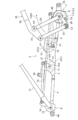
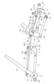
- FIG. 3 is a cross-sectional view of the second holder member along the line AA in FIG. 2. It is a top view in operation of the wiper device for vehicles concerning an embodiment of art of this indication. It is a top view in operation of the wiper device for vehicles concerning an embodiment of art of this indication. It is a top view in operation of the wiper device for vehicles concerning an embodiment of art of this indication. It is a top view in operation of the wiper device for vehicles concerning an embodiment of art of this indication. It is a top view in operation of the wiper device for vehicles concerning an embodiment of art of this indication. It is a top view in operation of the wiper device for vehicles concerning an embodiment of art of this indication.
- FIG. 1 It is a top view in operation of the wiper device for vehicles concerning an embodiment of art of this indication. It is a circuit diagram showing typically the circuit of the wiper system concerning an embodiment of art of this indication. An example of the 2nd output axis rotation angle map which prescribed
- an enlargement change process for changing the enlargement ratio (degree of extension) of the passenger-side wiper arm such as a change from the normal wiping operation to the enlarged wiping operation, etc. It is the flowchart which showed an example.
- FIG. 6 shows an example of a time-series change in the rotation angle of the output shaft of the second motor according to the embodiment of the technology of the present disclosure.
- FIG. An example of the 2nd output axis rotation angle map which prescribed
- FIG. 1 is a schematic diagram illustrating an example of a wiper system 100 including a vehicle wiper device (hereinafter referred to as “wiper device”) 2 according to an embodiment of the technology of the present disclosure.
- a wiper system 100 shown in FIG. 1 is for wiping a windshield glass 1 as a “windshield” provided in a vehicle such as a passenger car, for example, and includes a pair of wiper arms (driver seat side wiper arms described later). 17 and the passenger seat side wiper arm 35), the first motor 11, the second motor 12, the control circuit 52, the drive circuit 56, and the washer device 70.
- FIG. 1 shows the case of a right-hand drive vehicle
- the right side of the vehicle (left side of FIG. 1) is the driver's seat side
- the left side of the vehicle (right side of FIG. 1) is the passenger seat side.
- the left side of the vehicle (right side in FIG. 1) is the driver's seat side
- the right side of the vehicle (left side in FIG. 1) is the passenger seat side.
- the configuration of the wiper device 2 is opposite to the left and right.
- the first motor 11 reciprocates each of the driver seat side wiper arm 17 and the passenger seat side wiper arm 35 on the windshield glass 1 by rotating the output shaft forward and backward within a range of a predetermined rotation angle. It is a driving source.
- the driver's seat side wiper arm 17 operates so that the driver's seat side wiper blade 18 wipes the upper inversion position P1D from the lower inversion position P2D.
- the wiper arm 35 operates so that the passenger-side wiper blade 36 wipes the upper inversion position P1P from the lower inversion position P2P.
- the driver's seat side wiper arm 17 When the first motor 11 rotates in the reverse direction, the driver's seat side wiper arm 17 operates so that the driver's seat side wiper blade 18 wipes the upper inverted position P1D to the lower inverted position P2D, and the passenger seat side wiper arm 35
- the passenger-side wiper blade 36 operates so as to wipe from the upper inversion position P1P to the lower inversion position P2P.
- the outer edge portion of the windshield glass 1 is a light shielding portion 1A coated with a ceramic black pigment in order to block visible light and ultraviolet rays.
- the black pigment is applied to the outer edge of the windshield glass 1 on the vehicle interior side, and then melted by being heated at a predetermined temperature, and is fixed on the vehicle interior side surface of the windshield glass 1.
- the windshield glass 1 is fixed to the vehicle body by an adhesive applied to the outer edge portion.
- the light shielding portion 1A that does not transmit ultraviolet rays is provided at the outer edge portion, so that the adhesive by ultraviolet rays is provided. Suppresses deterioration.
- first predetermined rotation angle a predetermined rotation angle
- the second motor 12 is positive at a rotation angle from 0 ° to a predetermined rotation angle (hereinafter referred to as “second predetermined rotation angle”) of an output shaft of the second motor 12 (second output shaft 12A described later).
- second predetermined rotation angle a predetermined rotation angle
- This is a drive source that apparently extends the wiper arm 35 on the passenger seat side by rotating and reversely rotating.
- the passenger seat side wiper arm 35 is apparently extended upward on the passenger seat side, and the passenger seat side wiper blade 36 wipes the wiping range Z2.
- the magnitude of the second predetermined rotation angle it is possible to change the range in which the passenger seat side wiper arm 35 extends. For example, if the second predetermined rotation angle is increased, the range in which the passenger seat side wiper arm 35 extends is increased, and if the second predetermined rotation angle is decreased, the range in which the passenger seat side wiper arm 35 is extended is decreased.
- the first motor 11 and the second motor 12 are motors that can control the rotation direction of each output shaft to forward rotation and reverse rotation, and can also control the rotation speed of each output shaft. Either a DC motor with a brush or a brushless DC motor.
- a control circuit 52 for controlling each rotation is connected to the first motor 11 and the second motor 12.
- the control circuit 52 includes, for example, an absolute angle sensor (not shown) as a “rotation angle detector” provided near the output shaft ends of the first motor 11 and the second motor 12.
- the duty ratio of the voltage applied to each of the first motor 11 and the second motor 12 based on the detected rotation direction, rotation position, rotation speed, and rotation angle of the output shaft of each of the first motor 11 and the second motor 12. Is calculated.
- the voltage applied to each of the first motor 11 and the second motor 12 is a pulse width that modulates the voltage (approximately 12V) of the on-vehicle battery as a power source by turning on and off the switching element by a switching element.
- Generated by modulation PWM
- the duty ratio is a ratio of the time of one pulse generated when the switching element is turned on with respect to one period of a waveform of a voltage generated by PWM.
- One period of the waveform of the voltage generated by PWM is the sum of the time of the one pulse described above and the time during which the switching element is turned off and no pulse is generated.
- the drive circuit 56 turns on and off switching elements in the drive circuit 56 in accordance with the duty ratio calculated by the control circuit 52 to generate voltages to be applied to the first motor 11 and the second motor 12, and the generated voltages are supplied to the first circuit. The voltage is applied to each winding terminal of the first motor 11 and the second motor 12.
- each of the first motor 11 and the second motor 12 has a speed reduction mechanism composed of a worm gear
- the rotation direction, the rotation speed, and the rotation angle of each output shaft are the first
- the rotation speed and rotation angle of the motor 11 main body and the second motor 12 main body are not the same.
- each motor and each speed reduction mechanism are inseparably configured. Therefore, hereinafter, the rotation speed and the rotation angle of each output shaft of the first motor 11 and the second motor 12 are expressed as follows. The rotation direction, rotation speed, and rotation angle of each of the first motor 11 and the second motor 12 are considered.
- the absolute angle sensor is provided, for example, in each speed reduction mechanism of the first motor 11 and the second motor 12, and converts the magnetic field (magnetic force) of an excitation coil or a magnet that rotates in conjunction with each output shaft into a current. It is a sensor to detect, and as an example, a magnetic sensor such as an MR sensor.
- the control circuit 52 determines the position of the driver's seat side wiper blade 18 on the windshield glass 1 from the rotation angle of the output shaft of the first motor 11 detected by an absolute angle sensor provided near the output shaft end of the first motor.
- a computable microcomputer 58 is provided. The microcomputer 58 controls the drive circuit 56 so that the rotational speed of the output shaft of the first motor 11 changes according to the calculated position.
- the microcomputer 58 detects the rotation angle of the output shaft of the first motor 11 detected by the absolute angle sensor provided near the output shaft end of the first motor on the windshield glass 1 of the passenger side wiper blade 36. The position is calculated, and the drive circuit 56 is controlled so that the rotational speed of the output shaft of the second motor 12 changes according to the calculated position. Further, the microcomputer 58 calculates the degree of extension of the passenger seat side wiper arm 35 from the rotation angle of the output shaft of the second motor 12 detected by the absolute angle sensor provided near the output shaft end of the second motor 12.
- the control circuit 52 is provided with a memory 60 that is a storage device that stores data and programs used to control the drive circuit 56.
- the memory 60 stores the first motor 11 and the second motor 12 according to the rotation angle of the output shaft of the first motor 11 indicating the positions of the driver-side wiper blade 18 and the passenger-side wiper blade 36 on the windshield glass 1. Data and a program for calculating the rotation speed and the like (including the rotation angle) of each output shaft are stored.
- the microcomputer 58 is connected to a vehicle ECU (Electronic Control Unit) 90 that controls the vehicle engine and the like. Further, the vehicle ECU 90 includes a wiper switch 50, a direction indicator switch 54, a washer switch 62, a rain sensor 76, a vehicle speed sensor 92 for detecting the vehicle speed, an in-vehicle camera 94 for photographing the front of the vehicle, a GPS (Global Positioning System). ) A device 96 and a steering angle sensor 98 are connected.
- a vehicle ECU Electronic Control Unit
- the vehicle ECU 90 includes a wiper switch 50, a direction indicator switch 54, a washer switch 62, a rain sensor 76, a vehicle speed sensor 92 for detecting the vehicle speed, an in-vehicle camera 94 for photographing the front of the vehicle, a GPS (Global Positioning System). )
- a device 96 and a steering angle sensor 98 are connected.
- the wiper switch 50 is a switch that turns on or off the power supplied from the vehicle battery to the first motor 11.
- the wiper switch 50 is a low-speed operation mode selection position for operating the driver-side wiper blade 18 and the passenger-side wiper blade 36 at a low speed, a high-speed operation mode selection position for operating at a high speed, and an intermittent operation that operates intermittently at a constant cycle.
- the mode selection position can be switched to an AUTO (auto) operation mode selection position and a storage (stop) mode selection position that are operated when the rain sensor 76 detects raindrops. Further, a signal corresponding to the selected position of each mode is output to the microcomputer 58 via the vehicle ECU 90.
- the microcomputer 58 controls the memory 60 to control corresponding to the output signal from the wiper switch 50. This is done using stored data and programs.
- the wiper switch 50 is separately provided with an expansion mode switch for changing the wiping range of the passenger-side wiper blade 36 to the wiping range Z2.
- a predetermined signal is input to the microcomputer 58 via the vehicle ECU 90.
- the second motor 12 is configured to wipe the wiping range Z2.
- the direction indicator switch 54 is a switch for instructing the operation of a vehicle direction indicator (not shown).
- a signal for turning on the right or left direction indicator is operated to the vehicle ECU 90 by a driver's operation. Output.
- the vehicle ECU 90 causes the right or left direction indicator lamp to blink based on the signal output from the direction indicator switch 54.
- a signal output from the direction indicator switch 54 is also input to the microcomputer 58 via the vehicle ECU 90.
- the washer switch 62 is a switch for turning on or off the power supplied from the battery of the vehicle to the washer motor 64, the first motor 11 and the second motor 12.
- the washer switch 62 is provided integrally with an operating means such as a lever provided with the wiper switch 50 described above, and is turned on by an operation such as pulling the lever or the like by a passenger.
- the microcomputer 58 operates the washer motor 64 and the first motor 11.
- the wiper blade 36 on the passenger side wipes from the lower reverse position P2P to the upper reverse position P1P
- the microcomputer 58 wipes the wiper blade 36 from the upper reverse position P1P so as to wipe the wiping range Z2.
- the second motor 12 is controlled so as to wipe the wiping range Z1. With this control, the passenger seat side of the windshield glass 1 can be wiped widely.
- the washer pump 66 While the washer switch 62 is on, the washer pump 66 is driven by the rotation of the washer motor 64 provided in the washer device 70.
- the washer pump 66 pumps the washer liquid in the washer liquid tank 68 to the driver side hose 72A or the passenger side hose 72B.
- the driver seat side hose 72A is connected to a driver seat side nozzle 74A provided below the driver seat side of the windshield glass 1.
- the passenger seat side hose 72B is connected to a passenger seat side nozzle 74B provided below the windshield glass 1 on the passenger seat side.
- the pumped washer liquid is sprayed onto the windshield glass 1 from the driver seat side nozzle 74A and the passenger seat side nozzle 74B.
- the washer liquid adhering to the windshield glass 1 is wiped together with dirt on the windshield glass 1 by the operating driver side wiper blade 18 and the passenger seat side wiper blade 36.
- the microcomputer 58 controls the washer motor 64 so that it operates only while the washer switch 62 is on. Further, even when the washer switch 62 is turned off, the microcomputer 58 continues to operate until the driver seat side wiper blade 18 and the passenger seat side wiper blade 36 reach the lower reverse positions P2D and P2P. To control. Further, when the washer switch 62 is turned off when the driver-side wiper blade 18 and the passenger-side wiper blade 36 are wiped toward the upper inversion positions P1D and P1P, the microcomputer 58 The second motor 12 is controlled to wipe the wiping range Z2 until the wiper blade 18 and the passenger-side wiper blade 36 reach the upper inversion positions P1D and P1P by the rotation of the first motor 11.
- the rain sensor 76 is a kind of optical sensor provided on the vehicle interior side of the windshield glass 1, for example, and detects water droplets on the surface of the windshield glass 1.
- the rain sensor 76 includes, as an example, an LED that is an infrared light emitting element, a photodiode that is a light receiving element, a lens that forms an infrared optical path, and a control circuit. Infrared light emitted from the passenger compartment side by the LED is totally reflected by the windshield glass 1, but if there are water droplets on the surface of the windshield glass 1, some of the infrared rays pass through the water droplets and are emitted to the outside. The amount of reflection at the windshield glass 1 is reduced. As a result, the amount of light entering the photodiode that is the light receiving element is reduced. Based on the decrease in the amount of light, water droplets on the surface of the windshield glass 1 are detected.
- the vehicle speed sensor 92 is a sensor that detects the rotational speed of the vehicle wheel and outputs a signal indicating the rotational speed.
- the vehicle ECU 90 calculates the vehicle speed from the signal output from the vehicle speed sensor 92 and the circumference of the wheel.
- the in-vehicle camera 94 is a device that captures the front of the vehicle and acquires moving image data.
- the vehicle ECU 90 can determine whether the vehicle is approaching a curve or the like by performing image processing on moving image data acquired by the in-vehicle camera 94. Further, the vehicle ECU 90 can calculate the brightness in front of the vehicle from the luminance of the moving image data acquired by the in-vehicle camera 94.
- the rain sensor 76 and the in-vehicle camera 94 are provided on the vehicle side of the windshield glass 1.
- the rain sensor 76 detects raindrops and the like on the windshield glass 1 through the windshield glass 1 from the passenger compartment side, and the in-vehicle camera 94 images the front of the vehicle through the windshield glass 1.
- the GPS device is a device that calculates the current position of the vehicle based on a positioning signal received from a GPS satellite in the sky.
- the GPS device 96 dedicated to the wiper system 100 is used.
- the other GPS device may be used.
- the steering angle sensor 98 is a sensor that is provided on a rotating shaft (not shown) of the steering as an example and detects the rotating angle of the steering.
- the wiper device 2 has a plate-like central frame 3 and one end fixed to the central frame 3, and both sides of the central frame 3 in the vehicle width direction.
- a pair of pipe frames 4 and 5 are provided.
- a first holder member 6 including a driver seat side pivot shaft 15 of the driver seat side wiper arm 17 and the like is formed at the other end portion of the pipe frame 4.
- the second holder member 7 provided with the second passenger seat side pivot shaft 22 of the passenger seat side wiper arm 35 and the like is formed at the other end portion of the pipe frame 5.
- the wiper device 2 is supported on the vehicle by a support portion 3A provided on the central frame 3, and each of the fixing portion 6A of the first holder member 6 and the fixing portion 7A of the second holder member 7 is attached to the vehicle by a bolt or the like. By being fastened, it is fixed to the vehicle.
- the wiper device 2 includes a first motor 11 and a second motor 12 for driving the wiper device 2 on the back surface (the surface facing the passenger compartment side) of the central frame 3.
- the first output shaft 11A of the first motor 11 passes through the central frame 3 and protrudes from the surface of the central frame 3 (surface on the outside of the vehicle), and a first drive crank arm is provided at the tip of the first output shaft 11A.
- One end of 13 is fixed.
- the second output shaft 12A of the second motor 12 passes through the central frame 3 and protrudes from the surface of the central frame 3, and one end of the second drive crank arm 14 is fixed to the tip of the second output shaft 12A.
- a driver seat side pivot shaft 15 is rotatably supported by the first holder member 6, and one end of the driver seat side swing lever 16 is provided at the base end portion (the back side in FIG. 2) of the driver seat side pivot shaft 15.
- the arm head of the driver's seat side wiper arm 17 is fixed to the tip of the driver's seat side pivot shaft 15 (front side in FIG. 2).
- a driver seat side wiper blade 18 for wiping the driver seat side of the windshield glass 1 is connected to the tip of the driver seat side wiper arm 17.
- the other end of the first drive crank arm 13 and the other end of the driver seat side swing lever 16 are connected via a first connecting rod 19.
- the driver seat side swing lever 16 rotates, and the rotational force is transmitted to the driver seat side swing lever 16 via the first connecting rod 19, and the driver seat side swing lever 16. Sway.
- the driver seat side wiper arm 17 is also swung, and the driver seat side wiper blade 18 wipes the wiping range H1 between the lower inversion position P2D and the upper inversion position P1D.
- FIG. 3 is a cross-sectional view of the second holder member 7 taken along line AA in FIG.
- the first holder seat side pivot shaft 21 is supported on the second holder member 7 so as to be rotatable about the first axis L1
- the second passenger seat side pivot shaft 22 is secondly supported. It is supported so as to be rotatable about the axis L2.
- the first axis L1 and the second axis L2 are arranged on the same straight line L (concentric).
- FIG. 3 shows a state where the waterproof cover K shown in FIG. 2 and FIGS. 4 to 8 is removed.
- the cylindrical part 7B is formed in the second holder member 7, and the first passenger seat side pivot shaft 21 is rotatably supported via a bearing 23 on the inner peripheral side of the cylindrical part 7B.
- the first passenger seat side pivot shaft 21 is formed in a cylindrical shape, and the second passenger seat side pivot shaft 22 is rotatably supported via a bearing 24 on the inner peripheral side of the first passenger seat side pivot shaft 21. .
- first passenger seat side swing lever 25 is fixed to the base end portion of the first passenger seat side pivot shaft 21, and the first drive lever 26 has a first drive lever 26 attached to the distal end portion of the first passenger seat side pivot shaft 21. One end is fixed.
- the other end of the first passenger seat side swing lever 25 and the other end of the driver seat side swing lever 16 are connected by a second connecting rod 27. Accordingly, when the first motor 11 is driven and the driver's seat side swing lever 16 is pivoted, the second connecting rod 27 transmits the driving force to the first passenger's seat side swing lever 25 and the first passenger seat side swing lever. 25, the first drive lever 26 is swung (rotated) around the first axis L1.
- the second passenger seat side pivot shaft 22 is formed longer than the first passenger seat side pivot shaft 21, and the base end portion and the distal end portion of the second passenger seat side pivot shaft 22 are the first.
- One end of a second passenger seat side swinging lever 28 is fixed to the base end portion of the second passenger seat side pivot shaft 21 so as to protrude in the axial direction from the passenger seat side pivot shaft 21.
- One end of the second drive lever 29 is fixed to the tip portion.
- the other end of the second drive crank arm 14 and the other end of the second passenger seat side swing lever 28 are connected by a third connecting rod 31. Therefore, when the second motor 12 is driven, the second drive crank arm 14 rotates, and the third connecting rod 31 transmits the driving force of the second drive crank arm 14 to the second passenger seat side swing lever 28.
- the second drive lever 29 is swung (rotated) together with the second passenger seat-side rocking lever 28.
- the first passenger seat side pivot shaft 21 and the second passenger seat side pivot shaft 22 are provided coaxially, but the first passenger seat side pivot shaft 21 and the second passenger seat side pivot shaft 22 are not mutually connected.
- the first passenger seat side pivot shaft 21 and the second passenger seat side pivot shaft 22 are not interlocked and rotate independently of each other.
- the wiper device 2 includes a first driven lever having a base end portion coupled to a third axis L3 on the other end side of the first drive lever 26 so as to be rotatable. 32.
- the wiper device 2 has a base end portion coupled to be rotatable about a fourth axis L4 on the distal end side of the first driven lever 32 and a fifth axis L5 on the other end side of the second drive lever 29.
- An arm head 33 which is a second driven lever having a distal end connected to be rotatable about the center is provided.
- the arm head 33 constitutes a passenger-side wiper arm 35 together with a retainer 34 whose base end is fixed to the distal end of the arm head 33.
- a front passenger side wiper blade 36 for wiping the front passenger side of the windshield glass 1 is connected to the front end of the front passenger side wiper arm 35.
- the first drive lever 26, the second drive lever 29, the first driven lever 32, and the arm head 33 have a length from the first axis L1 (second axis L2) to the third axis L3, and from the fourth axis L4 to the fifth. It connects so that the length to the axis line L5 may become the same.
- the first drive lever 26, the second drive lever 29, the first driven lever 32, and the arm head 33 have a length from the third axis L3 to the fourth axis L4, and the first axis L1 (second axis L2) to the fifth. It connects so that the length to the axis line L5 may become the same.
- first drive lever 26 and the arm head 33 are kept parallel, and the second drive lever 29 and the first driven lever 32 are kept parallel.
- the first drive lever 26 and the second drive lever 29, the 1st driven lever 32, and the arm head 33 comprise the link mechanism of a substantially parallelogram shape.
- the fifth axis L5 is a fulcrum when the passenger-side wiper arm 35 operates.
- the passenger-side wiper arm 35 is rotated about the fifth axis L5 by the driving force of the first motor 11 to windshield glass. Reciprocates on 1.
- the second motor 12 passes the fifth axis L5 through a substantially parallelogram link mechanism including the first drive lever 26, the second drive lever 29, the first driven lever 32, and the arm head 33.
- the windshield glass 1 is moved more than in the case of FIGS.
- the passenger side wiper arm 35 is apparently extended. Accordingly, when the second motor 12 is operated together with the first motor 11, the passenger side wiper blade 36 wipes the wiping range Z2.
- the fifth axis L5 starts from the position shown in FIGS. 2, 7, and 8 (hereinafter referred to as “first position”). It does n’t move. Accordingly, the passenger side wiper arm 35 operates between the lower inversion position P2P and the upper inversion position P1P while drawing a substantially arc-shaped locus around the fifth axis L5 whose position does not change, and the passenger seat side wiper blade 36 The substantially fan-shaped wiping range Z1 is wiped.
- the wiping range Z2 is wiped when the passenger seat wiper blade 36 moves from the lower inversion position P2P to the upper inversion position P1P.
- the first motor 11 and the second motor 12 are each controlled.
- the first motor 11 and the second motor 12 are respectively controlled so as to wipe the wiping range Z1 when the passenger seat wiper blade 36 reversed at the upper reversing position P1P moves toward the lower reversing position P2P.
- the wiping range Z2 is wiped in the forward movement and the wiping range Z1 is wiped in the backward movement.
- the wiping range Z1 is wiped in the forward movement and the wiping range Z2 is wiped in the backward movement.
- a wide range of windshield glass 1 can be wiped off.
- the wiping range Z2 may be wiped at the time of forward movement and backward movement.
- the driver-seat-side wiper arm 17 and the driver-seat-side wiper blade 18 only operate around the driver-seat-side pivot shaft 15 according to the rotation of the first motor 11.
- the operation of the passenger side wiper blade 36 will be described in detail. Further, the following description of the operation of the wiper device 2 describes a case where enlarged wiping is performed during forward movement.
- FIG. 2 shows a state in which the passenger-side wiper blade 36 is positioned at the lower inversion position P2P, and the passenger-side wiper arm 35 is in the stop position.
- the first output shaft 11A of the first motor 11 is rotated in the rotation direction CC1 shown in FIG.
- the first drive lever 26 starts rotating
- the passenger seat side wiper arm 35 starts rotating around the fifth axis L5.
- the second output shaft 12A of the second motor 12 also starts to rotate in the rotational direction CC2 shown in FIG.
- the rotation in the rotation direction CC1 of the first output shaft 11A and the rotation in the rotation direction CC2 of the second output shaft 12A are defined as positive rotations in the respective output shafts.
- FIG. 4 shows a state where the passenger-side wiper blade 36 wipes the windshield glass 1 halfway (approximately 1/4 of the forward travel).
- the driving force generated by the rotation of the second motor 12 in the rotation direction CC ⁇ b> 2 is transmitted to the second drive lever 29.
- the second drive lever 29 to which the driving force of the second motor 12 is transmitted operates in the operation direction CW3, and the fifth axis L5, which is a fulcrum of the passenger seat side wiper arm 35, is located above the passenger seat side of the windshield glass 1. Move towards.
- FIG. 5 shows that when the first output shaft 11A is rotated to an intermediate rotation angle between 0 ° and the first predetermined angle, the first drive lever 26 is further rotated, and the front passenger side wiper blade 36 is in the lower inverted position. A case is shown in which a substantially intermediate point of the stroke (forward stroke) between P2P and the upper reversal position P1P is reached.
- the second output shaft 12A of the second motor 12 is also rotated to the second predetermined rotation angle in the rotation direction CC2 shown in FIG.
- the fifth axis L5 which is the fulcrum of the passenger-side wiper arm 35, is connected to the second drive crank arm 14, the third connecting rod 31, the second The passenger seat side swing lever 28 and the second drive lever 29 are lifted to the uppermost position (second position).
- the front end portion of the passenger seat side wiper blade 36 is moved to a position near the upper corner of the windshield glass 1 on the passenger seat side, as shown in FIG.
- the intermediate rotation angle described above is about half of the first predetermined rotation angle, but is set individually according to the shape of the windshield glass 1 and the like.
- the second position is a position at which the fifth axis L5 is disposed at the uppermost position in each magnification.
- the second position is determined when the first output shaft 11A is between 0 ° and the first predetermined angle when the passenger-side wiper blade wipes a range wider than the wiping range Z1 (for example, the wiping range Z2). This is the position at which the fifth axis L5 is arranged when rotated to the intermediate rotation angle.
- FIG. 6 shows that when the first drive lever 26 is further rotated, the passenger-side wiper blade 36 reaches approximately 3/4 of the stroke (forward stroke) between the lower inversion position P2P and the upper inversion position P1P. Shows the case.
- the rotation direction of the first output shaft 11A of the first motor 11 is the same as that of FIGS. 4 and 5, but the second output shaft 12A of the second motor 12 is opposite to the case of FIGS. It rotates in the rotation direction CW2 (reverse rotation).
- the second drive lever 29 operates in the operation direction CC3
- the fifth axis L5 which is a fulcrum of the passenger seat side wiper arm 35, is moved downward from the second position.
- the front passenger side wiper blade 36 moves on the windshield glass 1 while wiping the wiping range Z2 while drawing the locus indicated by the broken line above the wiping range Z2 shown in FIG.
- FIG. 7 shows a case where the first output shaft 11A of the first motor 11 rotates forward to the first predetermined rotation angle and the second output shaft 12A of the second motor 12 rotates reversely at the second predetermined rotation angle. Yes. Since the rotation angle of the first output shaft 11A of the first motor 11 in the forward rotation is maximized, the driver seat side wiper arm 17 and the driver seat side wiper blade 18 reach the upper inversion position P1D. Further, the second output shaft 12A of the second motor 12 is reversed at the second predetermined rotation angle from the state shown in FIG. 5 (the state where the second output shaft 12A has reached the second predetermined rotation angle by forward rotation).
- the fifth axis L5 which is the fulcrum of the passenger-side wiper arm 35, is at the first position, which is the position before the second output shaft 12A of the second motor 12 shown in FIG. I'm back.
- the passenger seat side wiper arm 35 and the passenger seat side wiper blade 36 reach the same upper inversion position P1P as the wiping range Z1 when the second motor 12 is not driven.
- FIG. 8 shows a state in which the driver's seat side wiper arm 17 and the driver's seat side wiper blade 18 and the passenger's seat side wiper arm 35 and the passenger's seat side wiper blade 36 move from the upper inverted positions P1D and P1P to the lower inverted positions P2D and P2P.
- the state (return stroke) is shown.
- the first output shaft 11A of the first motor 11 rotates in the reverse direction, and rotates in the rotation direction CW1 in the reverse direction to the case of FIGS.
- the second output shaft 12A of the second motor 12 does not rotate, and therefore the fifth axis L5, which is a fulcrum of the passenger seat side wiper arm 35, does not move from the first position, so the first output shaft 11A of the first motor 11 does not move.
- the passenger seat side wiper arm 35 draws a substantially arc-shaped locus.
- the passenger side wiper blade 36 connected to the front end of the passenger side wiper arm 35 wipes the wiping range Z1.
- the operation of the wiper device 2 when performing enlarged wiping during forward movement has been described.
- the first output shaft 11A of the first motor 11 is rotated in the rotational direction CW1
- the second output shaft 12A of the second motor 12 is illustrated.
- the extension of the passenger seat side wiper arm 35 is started.
- the second output shaft 12A is rotated to the second predetermined rotation angle.
- the passenger seat side wiper arm 35 is extended to the maximum.
- the second output shaft 12A is rotated in the rotational direction CW2 shown in FIG. 6 to converge the extended passenger seat side wiper arm 35.
- FIG. 9 is a circuit diagram schematically showing a circuit of the wiper system 100 according to the present embodiment. As shown in FIG. 9, the wiper system 100 includes a control circuit 52 and a drive circuit 56.
- control circuit 52 includes the microcomputer 58 and the memory 60.
- the microcomputer 58 includes a wiper switch 50, a direction indicator switch 54, a washer switch 62, a vehicle ECU 90 (not shown), A rain sensor 76, a vehicle speed sensor 92, an in-vehicle camera 94, a GPS device 96, and a steering angle sensor 98 are connected to each other.
- the drive circuit 56 includes a first pre-driver 104 and a first motor drive circuit 108 for driving the first motor 11, and a second pre-driver 106 and a second motor drive circuit 110 for driving the second motor 12. ing.
- the drive circuit 56 includes a relay drive circuit 78, an FET drive circuit 80, and a washer motor drive circuit 57 for driving the washer motor 64.
- the microcomputer 58 of the control circuit 52 rotates the first motor 11 via the second pre-driver 106 by turning on and off the switching elements constituting the first motor driving circuit 108 via the first pre-driver 104.
- the rotation of the second motor 12 is controlled by turning on and off the switching elements of the two-motor drive circuit 110.
- the microcomputer 58 controls the rotation of the washer motor 64 by controlling the relay drive circuit 78 and the FET drive circuit 80.
- the first motor drive circuit 108 and the second motor drive circuit 110 each include four switching elements.
- the switching element is, for example, an N-type FET (field effect transistor).
- the first motor drive circuit 108 includes FETs 108A to 108D.
- the FET 108 ⁇ / b> A has a drain connected to the power supply (+ B), a gate connected to the first pre-driver 104, and a source connected to one end of the first motor 11.
- the FET 108 ⁇ / b> B has a drain connected to the power supply (+ B), a gate connected to the first pre-driver 104, and a source connected to the other end of the first motor 11.
- the FET 108C has a drain connected to one end of the first motor 11, a gate connected to the first pre-driver 104, and a source grounded.
- the FET 108D has a drain connected to the other end of the first motor 11, a gate connected to the first pre-driver 104, and a source grounded.
- the first pre-driver 104 controls driving of the first motor 11 by switching a control signal supplied to the gates of the FETs 108A to 108D in accordance with a control signal from the microcomputer 58. That is, when the first pre-driver 104 rotates the first output shaft 11A of the first motor 11 in a predetermined direction (forward rotation), the first pre-driver 104 turns on the set of the FET 108A and the FET 108D and the first output of the first motor 11 When rotating the shaft 11A in the direction opposite to the predetermined direction (reverse rotation), the set of the FET 108B and the FET 108C is turned on. Further, the first pre-driver 104 performs PWM for intermittently turning on and off the FET 108A and the FET 108D based on a control signal from the microcomputer 58.
- the first pre-driver 104 controls the rotational speed of the first motor 11 in the forward rotation by changing the duty ratio related to the on / off of the FET 108A and the FET 108D by PWM. If the duty ratio is increased, the effective value of the voltage applied to the terminal of the first motor 11 during forward rotation is increased, and the rotation speed of the first motor 11 is increased.
- the first pre-driver 104 controls the rotational speed in the reverse rotation of the first motor 11 by changing the duty ratio related to on / off of the FET 108B and the FET 108C by PWM. If the duty ratio increases, the effective value of the voltage applied to the terminal of the first motor 11 during reverse rotation increases, and the rotation speed of the first motor 11 increases.
- the second motor drive circuit 110 includes FETs 110A to 110D.
- the FET 110 ⁇ / b> A has a drain connected to the power supply (+ B), a gate connected to the second pre-driver 106, and a source connected to one end of the second motor 12.
- the FET 110 ⁇ / b> B has a drain connected to the power supply (+ B), a gate connected to the second pre-driver 106, and a source connected to the other end of the second motor 12.
- the FET 110C has a drain connected to one end of the second motor 12, a gate connected to the second pre-driver 106, and a source grounded.
- the FET 110D has a drain connected to the other end of the second motor 12, a gate connected to the second pre-driver 106, and a source grounded.
- the second pre-driver 106 controls the driving of the second motor 12 by switching the control signal supplied to the gates of the FETs 110A to 110D in accordance with the control signal from the microcomputer 58. That is, when the second pre-driver 106 rotates the second output shaft 12A of the second motor 12 in a predetermined direction (forward rotation), the second pre-driver 106 turns on the set of the FET 110A and the FET 110D and outputs the second output of the second motor 12. When rotating the shaft 12A in the direction opposite to the predetermined direction (reverse rotation), the set of the FET 110B and the FET 110C is turned on.
- the second pre-driver 104 controls the rotational speed of the second motor 12 by performing PWM like the first pre-driver 104 described above based on the control signal from the microcomputer 58.
- a two-pole sensor magnet 112A is fixed to the output shaft end portion 112 of the first output shaft 11A in the speed reduction mechanism of the first motor 11, and a first absolute angle sensor 114 is provided so as to face the sensor magnet 112A. ing.
- a two-pole sensor magnet 116A is fixed to the output shaft end portion 116 of the second output shaft 12A in the speed reduction mechanism of the second motor 12, and a second absolute angle sensor 118 is provided so as to face the sensor magnet 116A. ing.
- the first absolute angle sensor 114 detects the magnetic field of the sensor magnet 112A
- the second absolute angle sensor 118 detects the magnetic field of the sensor magnet 116A, and outputs a signal corresponding to the detected magnetic field strength.
- the microcomputer 58 determines the rotational angle and rotational position of each of the first output shaft 11A of the first motor 11 and the second motor 12 based on the signals output from the first absolute angle sensor 114 and the second absolute angle sensor 118, respectively. The rotation direction and the rotation speed are calculated.
- the first absolute angle sensor 114 is an example of the “rotation angle detection unit” of the technology of the present disclosure.
- the position between the lower inversion position P2D and the upper inversion position P1D of the driver seat side wiper blade 18 can be calculated. Further, from the rotation angle of the second output shaft 12 ⁇ / b> A of the second motor 12, the degree of apparent extension (hereinafter simply referred to as extension) of the passenger-side wiper arm 35 can be calculated.
- the microcomputer 58 determines the rotation angle of the second output shaft 12A based on the position between the lower inversion position P2D and the upper inversion position P1D of the driver seat wiper blade 18 calculated from the rotation angle of the first output shaft 11A. By controlling the above, the operations of the first motor 11 and the second motor 12 are synchronized.
- the position (or the rotation angle of the first output shaft 11A) between the lower inversion position P2D and the upper inversion position P1D of the driver seat side wiper blade 18 and the rotation angle of the second output shaft 12A is stored in advance, and the rotation angle of the second output shaft 12A is controlled according to the rotation angle of the first output shaft 11A according to the map. .
- FIG. 10 shows an example of a second output shaft rotation angle map that defines the rotation angle of the second output shaft 12A according to the rotation angle of the first output shaft 11A in the present embodiment.
- the horizontal axis in FIG. 10 is the first output shaft rotation angle ⁇ A that is the rotation angle of the first output shaft 11A
- the vertical axis is the second output shaft rotation angle ⁇ B that is the rotation angle of the second output shaft 12A.
- the origin O in FIG. 10 shows a state in which the passenger seat side wiper blade 36 is at the lower inversion position P2P.
- ⁇ 1 indicates a state in which the passenger seat side wiper blade 36 is at the upper inversion position P1P as a result of the first output shaft 11A having rotated by the first predetermined rotation angle ⁇ 1 .
- the microcomputer 58 detects the rotation angle of the first output shaft 11A detected by the first absolute angle sensor 114 and the second output shaft. Check the rotation angle map. With this collation, the second output shaft rotation angle ⁇ B corresponding to the first output shaft rotation angle ⁇ A detected by the first absolute angle sensor 114 is calculated from the angle indicated by the curve 190 in FIG. so that the second output shaft rotation angle theta B controls the rotation angle of the second output shaft 12A of the second motor 12.
- the microcomputer 58 determines that the first absolute angle sensor 114 starts to change the rotation angle of the first output shaft 11A of the first motor 11 from 0 ° in the positive rotation direction. It is determined that the blade 36 has started to move from the lower inversion position P2P, and the second output shaft 12A starts to rotate forward. As described above, the microcomputer 58 determines the rotation angle of the second output shaft 12A corresponding to the rotation angle of the first output shaft 11A using the second output shaft rotation angle map. 2 The rotation angle of the second output shaft 12A is monitored based on the signal from the absolute angle sensor 118, and the rotation of the second motor 12 is controlled so as to be the rotation angle determined using the second output shaft rotation angle map. .
- the first output shaft rotation angle ⁇ A becomes an intermediate rotation angle ⁇ m between 0 ° and the first predetermined rotation angle ⁇ 1.
- the rotation angle in the forward rotation of the second output shaft 12A is set to be a second predetermined rotational angle theta 2.
- the fifth axis L5 which is the fulcrum of the passenger seat side wiper arm 35, is positioned above the passenger seat side on the windshield glass 1 ( To the second position).
- the second output shaft 12A After the rotation angle in the forward rotation of the second output shaft 12A reaches a second predetermined rotational angle theta 2, in accordance with the second output shaft rotation angle map, reduces the rotation angle of the second output shaft 12A. Specifically, when the rotation angle of the first output shaft 11A reaches the first predetermined rotation angle ⁇ 1 and the passenger seat side wiper blade 36 reaches the upper inversion position P1P, the second output shaft 12A is set to the second predetermined rotation angle. By rotating in reverse at the rotation angle ⁇ 2 , the rotation angle of the second output shaft 12A is reduced to 0 °. By the reverse rotation of the second output shaft 12A, the fifth axis L5 that is the fulcrum of the passenger seat side wiper arm 35 is returned to the original position (first position).
- the wiping range Z2 is wiped while the passenger seat side wiper blade 36 is moved from the lower inversion position P2P to the upper inversion position P1P.
- the rotation angle of the first output shaft 11A is reversed from 0 ° by the first absolute angle sensor 114.
- the change starts in the rotation direction it is determined that the passenger-side wiper blade 36 has started to move from the upper reversal position P1P, and the second output shaft 12A of the second motor 12 starts to rotate forward.
- the second output shaft rotation angle map shown in FIG. 10 is has a symmetrical curve 190 by an intermediate rotation angle theta m to the shaft, but is not limited thereto. The curve of the map is set individually according to the shape of the windshield glass 1 and the like.
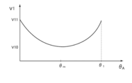
- the microcomputer 58 changes the wiping speed of the wiper blade based on the position between the lower inversion position P2D and the upper inversion position P1D of the driver seat side wiper blade 18 and the degree of enlargement of the passenger seat side wiper arm 35. It is also possible to perform control such as Hereinafter, an example of wiping speed control when the second predetermined rotation angle, which is the rotation angle of the second output shaft 12A, is set to be large and the degree of enlargement of the passenger-side wiper arm 35 is increased will be described. In such a case, the rotation speed of the first output shaft 11A is gradually reduced as the rotation angle of the first output shaft 11A of the first motor 11 approaches the intermediate rotation angle.
- the rotation angle of the first output shaft 11A reaches the intermediate rotation angle, that is, when the passenger seat side wiper arm 35 is extended to the maximum, control is performed so that the rotation speed of the first output shaft 11A is minimized.
- a map of the rotation speed of the first output shaft 11A defined according to the rotation angle of the first output shaft 11A is used for controlling the rotation speed of the first output shaft 11A.
- the rotational speed of the second output shaft 12A is also controlled in accordance with the rotational speed of the first output shaft 11A. For example, if the second output shaft rotation angle map as shown in FIG. 10 is used, the rotation of the second output shaft 12A can be synchronized with the rotation of the first output shaft 11A.
- the rotational speed of the second output shaft 12A can also be controlled. With this control, the speed at which the passenger-side wiper arm 35 is extended and the wiping speed of the passenger-side wiper blade 36 can be alleviated, and the possibility that the occupant feels an uncomfortable feeling that “the passenger-side wiper arm 35 has suddenly extended” can be reduced. .
- the washer motor drive circuit 57 includes a relay unit 84 incorporating two relays RLY1 and RLY2, and two FETs 86A and 86B.
- the relay coils of the relays RLY1 and RLY2 of the relay unit 84 are connected to the relay drive circuit 78, respectively.
- the relay drive circuit 78 switches the relays RLY1 and RLY2 on and off (excitation / excitation stop of the relay coil). When the relay coils are not excited, the relays RLY1 and RLY2 maintain the state in which the common terminals 84C1 and 84C2 are connected to the first terminals 84A1 and 84A2 (off state), respectively, and the relay coils are excited.
- the common terminals 84C1 and 84C2 are switched to the state of connecting to the second terminals 84B1 and 84B2, respectively.
- the common terminal 84C1 of the relay RLY1 is connected to one end of the washer motor 64, and the common terminal 84C2 of the relay RLY2 is connected to the other end of the washer motor 64.
- the first terminals 84A1 and 84A2 of the relays RLY1 and RLY2 are connected to the drain of the FET 86B, and the second terminals 84B1 and 84B2 of the relays RLY1 and RLY2 are connected to the power source (+ B).
- the FET 86B has a gate connected to the FET drive circuit 80 and a source grounded. The duty ratio related to the on / off of the FET 86B is controlled by the FET drive circuit 80.
- An FET 86A is provided between the drain of the FET 86B and the power source (+ B). The FET 86A is provided for the purpose of using a parasitic diode for absorbing a surge without switching on and off because no control signal is input to the gate.
- the relay driving circuit 78 and the FET driving circuit 80 control the driving of the washer motor 64 by switching on and off the two relays RLY1, RLY2 and the FET 86B. That is, when rotating the output shaft of the washer motor 64 in a predetermined direction (forward rotation), the relay drive circuit 78 turns on the relay RLY1 (relay RLY2 is off), and the FET drive circuit 80 turns on the FET 86B with a predetermined duty ratio. Let With the above control, the rotation speed of the output shaft of the washer motor 64 is controlled.
- FIG. 11 shows an example of a process for changing the position of the wiping range of the passenger-side wiper arm 35 such as a change from the normal wiping operation to the enlarged wiping operation in the wiper device 2 according to the present embodiment. It is a flowchart. A series of procedures shown in FIG. 11 is processed by the microcomputer 58 in the control circuit 52.
- step 110 it is determined whether or not a change signal indicating that the enlargement mode switch provided in the wiper switch 50 is turned on is input. If the determination is affirmative, the procedure proceeds to step 112, and In the case of determination, the process is returned.
- step 112 based on the first output shaft rotation angle theta A detected by the first absolute angle sensor 114, calculates the position of the passenger's side wiper blades 36, is the calculated position of the passenger side wiper blade 36 It is determined whether or not the upper inversion position P1P or the lower inversion position P2P.
- an enlarged wiping operation is performed during forward movement and a normal wiping operation is performed during backward movement, and a normal wiping operation is performed during forward movement and an enlarged wiping operation is performed during backward movement.
- expansion wiping operation at the time of backward movement.
- the passenger seat side wiper blade 36 starts to extend after the passenger seat side wiper blade 36 is inverted at the lower inversion position P2P.
- the reversal position P2P is reached, an affirmative determination is made.
- the extension of the passenger seat side wiper arm 35 starts after the passenger seat side wiper blade 36 is inverted at the upper inversion position P1P. Affirmative determination is made when reaches the upper inversion position P1P.
- FIG. 12 shows an example of a time-series change in the rotation angle (second output shaft rotation angle ⁇ B ) of the output shaft 12A of the second motor 12 according to the present embodiment.
- FIG. 12 shows a case where the expansion mode switch is turned on at time t 1 (0 ⁇ t 1 ⁇ t 2 ), but the angle curve 170 showing the change in the second output shaft rotation angle ⁇ B is 0 °. Therefore, the second output shaft 12A is not rotating.
- Step 114 is an example of the “wiping range position changing step” of the technique of the present disclosure.
- the passenger side wiper arm 35 is indicated by the first output shaft rotation angle theta A that it has reached the lower reversing position P2P or upper turning position P1P was first absolute angle sensor 114 detects First, the second output shaft 12A of the second motor 12 is started to be controlled in accordance with the enlarged wiping operation map 172, thereby rotating the second output shaft 12A.
- the extension of the passenger seat side wiper arm 35 is not performed immediately after the enlargement mode switch is turned on, but when the passenger seat side wiper blade 36 reaches the lower inversion position P2P or the upper inversion position P1P.
- the enlargement mode switch As a result, after the enlargement mode switch is operated, it is possible to control to start the enlargement wiping operation without a sense of incongruity.
- the technology of the present disclosure is not limited to this, and it may be determined whether or not the position of the passenger-side wiper blade 36 is located within a predetermined range near the upper reversal position P1P or the lower reversal position P2P. Good.
- the process which changes the position of the wiping range in step 114 of FIG. 11 illustrated the change from the normal wiping operation in which the enlargement rate is 0% to the enlarged wiping operation in which the enlargement rate is 100%.
- an enlargement ratio change switch that can arbitrarily set an enlargement ratio indicating the degree of extension of the passenger-side wiper arm 35 in the range of 0 to 100% may be provided separately.
- the enlargement ratio is an example of the “degree of change in the position of the wiping range” in the technology of the present disclosure.
- the enlargement ratio changing switch is an example of the “degree changing unit” in the technology of the present disclosure.
- the extension of the passenger-side wiper arm 35 is controlled in accordance with the wiping range expansion ratio X indicated by a numerical value of 0 to 1.0.
- the rotation angle of the second output shaft 12A so as to be the second output shaft rotation angle ⁇ B calculated by the enlargement factor X, the second output shaft rotation angle map shown in FIG. 13, and the following equation (1).
- ⁇ A in the above equation (1) is the first output shaft rotation angle ⁇ A that is the rotation angle of the first output shaft 11A shown in FIGS. f (theta A) is shown by curve 190 in FIG. 13, when the enlargement ratio X is 1.0 (100% equivalent), a second output shaft which is determined in response to the first output shaft rotation angle theta A The rotation angle is 12A.
- g ( ⁇ A ) is a second output shaft that is determined according to the first output shaft rotation angle ⁇ A when the enlargement ratio X is 0 (corresponding to 0%) shown by the curve 194 in FIG.
- the rotation angle is 12A.
- the rotation angle g ( ⁇ A ) of the second output shaft 12A is the value of the first output shaft rotation angle ⁇ A. Regardless of whether it is always 0 °.
- the driving of the first motor 11 that reciprocates the driver-side wiper arm 17 and the passenger-side wiper arm 35 also to the link mechanism that moves the fifth axis L5 that is the fulcrum of the passenger-side wiper arm 35 is performed.
- the force may be affected, and g ( ⁇ A ) may not always be 0 ° regardless of the value of the first output shaft rotation angle ⁇ A in practice.
- a curve 192 in FIG. 13 represents the second output shaft rotation angle ⁇ B when the enlargement ratio X calculated based on the above equation (1) is 0.5 (equivalent to 50%).
- the second output shaft rotation angle ⁇ B indicated by the curve 192 is approximately 1 ⁇ 2 of the angle indicated by the curve 190 when the enlargement ratio X is equivalent to 100%.
- FIG. 14 shows an example of a change in the wiping range according to the enlargement ratio X.
- the wiping range Z1 shows the case where the enlargement ratio X is equivalent to 0%
- the wiping range Z2 shows the case where the enlargement ratio X is equivalent to 100%
- the wiping range Z3 shows the case where the enlargement ratio X is equivalent to 50%. Yes.
- the operation that the passenger seat side wiper arm 35 is suddenly extended is further suppressed, and the enlargement wiping operation with less uncomfortable feeling is possible. become.
- the switch for performing the enlarged wiping operation when the switch for performing the enlarged wiping operation is turned on, the enlarged wiping operation is not started immediately after the switch is turned on.
- the position of the passenger-side wiper blade 36 indicated by the first output shaft rotation angle ⁇ A that is the rotation angle of the first output shaft 11A detected by the first absolute angle sensor 114 is the lower inversion position P2P or the upper position.
- the enlarged wiping operation is started.
- the enlarged wiping is not performed only on the condition that the switch for performing the enlarged wiping operation is turned on, and the rotation angle of the first output shaft 11A (first output shaft rotation angle ⁇ A ) is the passenger seat side wiper.
- the angle corresponds to the lower reversal position P2P or the upper reversal position P1P of the blade 36, the enlarged wiping operation is started.
- the passenger-seat-side wiper blade 36 that has reached the lower inversion position P2P or the upper inversion position P1P reverses immediately thereafter and starts moving forward or backward.
- the rotation angle (second phase) of the second output shaft 12A of the second motor 12 according to the map shown in FIGS. controlling the output shaft rotational angle theta B). Therefore, it is possible to provide a vehicle wiper device and a method for controlling the vehicle wiper device that can reduce a feeling of strangeness in the change in the position of the wiper arm wiping range.
- the first output shaft 11A of the first motor 11 and the second output shaft 12A of the second motor 12 are controlled to be able to rotate forward and backward (reciprocating).
- the present embodiment is limited to this. There is no.
- one of the first output shaft 11A and the second output shaft 12A may rotate in one direction.
- the rotation of the first output shaft 11A of the first motor 11 causes the driver-side wiper blade 18 and the passenger-side wiper blade 36 to move upside-down positions P1D and P1P and downside-inversion positions P2D and P2P.
- the first motor 11 includes a “driver's seat side first motor” and a “passenger's seat side first motor”, and the driver seat side wiper blade 18 is moved down to the upper inversion position P1D by the rotation of the driver seat side first motor.
- the structure may be such that the passenger seat side wiper blade 36 is moved between the upper inversion position P1P and the lower inversion position P2P by moving between the inversion position P2D and rotation of the first passenger seat side motor.
- the driver-side wiper blade 18 and the passenger-side wiper blade 36 are structured not to overlap in the vehicle width direction at the lower inversion positions P2D and P2P.
- the present invention is limited to this.
- the driver seat side wiper blade 18 side of the passenger seat side wiper blade 36 may be set longer.
- the length of the passenger seat side wiper blade 36 is set so that the driver seat side wiper blade 18 side of the passenger seat side wiper blade 36 overlaps the passenger seat side wiper blade 36 side of the driver seat side wiper blade 18. Also good. Thereby, when wiping the wiping range Z2 during the reciprocating motion, it is possible to reduce the non-wiping area that remains on the lower center side of the windshield glass.
- the passenger seat-side wiper arm 35 (passenger seat-side wiper blade 36) is extended to the vicinity of the intermediate angle at the predetermined rotation angle of the first output shaft 11A, and from the vicinity of the intermediate angle to the predetermined rotation angle.
- the passenger seat side wiper arm 35 (passenger seat side wiper blade 36) is controlled to be reduced, but the present invention is not limited to this.
- the passenger seat side wiper arm 35 may be controlled to gradually extend.
- the embodiment using the rotation angle of the first output shaft 11A of the first motor 11 and the rotation angle of the second output shaft 12A of the second motor 12 has been described.
- the rotational position of the first output shaft 11A and the rotational position of the second output shaft 12A may be used.
- the area of the wiper arm wiping range Z2 when the wiper arm wiping range position is changed is larger than the wiper arm wiping range Z1 (see FIG. 1) when the wiper arm wiping range position is not changed. Yes.
- the technology of the present disclosure is not limited to this.
- the wiping range Z1 and the wiping range Z2 may be the same, and the wiping range Z2 may be smaller than the wiping range Z1.
- Wind shield glass (wind shield), 1A ... Light-shielding part, 2 ... Wiper apparatus, 3 ... Center frame, 3A ... Support part, 4 ... Pipe frame, 5 ... Pipe frame, 6 ... 1st holder member, 6A ... Fixed 7, second holder member, 7 A, fixed portion, 7 B, cylindrical portion, 11, first motor, 11 A, first output shaft, 12, second motor, 12 A, second output shaft, 13, first.
- first Predriver 106 106
- Second predriver 108
- First motor drive circuit 110
- Second motor drive circuit 112
- Sensor magnet 114
- First absolute angle sensor 116
- Output shaft End part 116A
- sensor magnet 118
- second absolute angle sensor 122A, 122B
- area 135 ... passenger side wiper arm 136
- passenger side wiper blade 150P ... passenger side wiper arm 140 ... arrow 142 ... Trajectory, 150P ... passenger side wiper arm, 154P ... passenger side wiper blade, 158 ... non-wiping range, 16 0 ... 4 link mechanism, 164 ... enlarged wiping operation map, 170 ... angle curve, 172 ... enlarged wiping operation map, 190,192,194 ...
Landscapes
- Engineering & Computer Science (AREA)
- Mechanical Engineering (AREA)
- Control Of Direct Current Motors (AREA)
Abstract
Priority Applications (4)
| Application Number | Priority Date | Filing Date | Title |
|---|---|---|---|
| JP2017562537A JP6801678B2 (ja) | 2016-01-21 | 2017-01-12 | 車両用ワイパ装置及び車両用ワイパ装置の制御方法 |
| US16/069,169 US10479323B2 (en) | 2016-01-21 | 2017-01-12 | Vehicle wiper device and vehicle wiper device control method |
| CN201780007648.3A CN108473111B (zh) | 2016-01-21 | 2017-01-12 | 车辆用刮水器装置及车辆用刮水器装置的控制方法 |
| DE112017000449.7T DE112017000449T5 (de) | 2016-01-21 | 2017-01-12 | Fahrzeugwischervorrichtung und Verfahren zur Steuerung einer Fahrzeugwischervorrichtung |
Applications Claiming Priority (2)
| Application Number | Priority Date | Filing Date | Title |
|---|---|---|---|
| JP2016010044 | 2016-01-21 | ||
| JP2016-010044 | 2016-01-21 |
Publications (1)
| Publication Number | Publication Date |
|---|---|
| WO2017126415A1 true WO2017126415A1 (fr) | 2017-07-27 |
Family
ID=59362342
Family Applications (1)
| Application Number | Title | Priority Date | Filing Date |
|---|---|---|---|
| PCT/JP2017/000877 Ceased WO2017126415A1 (fr) | 2016-01-21 | 2017-01-12 | Dispositif d'essuie-glace de véhicule et son procédé de commande |
Country Status (5)
| Country | Link |
|---|---|
| US (1) | US10479323B2 (fr) |
| JP (1) | JP6801678B2 (fr) |
| CN (1) | CN108473111B (fr) |
| DE (1) | DE112017000449T5 (fr) |
| WO (1) | WO2017126415A1 (fr) |
Families Citing this family (4)
| Publication number | Priority date | Publication date | Assignee | Title |
|---|---|---|---|---|
| US11420594B2 (en) | 2017-08-28 | 2022-08-23 | Rosemount Aerospace Inc. | Configurable variable sweep variable speed wiper system |
| JP2023069757A (ja) * | 2021-11-08 | 2023-05-18 | 株式会社デンソー | 融雪装置 |
| DE102023123442A1 (de) | 2023-08-31 | 2025-03-06 | Bayerische Motoren Werke Aktiengesellschaft | Scheibenwischvorrichtung sowie Verfahren |
| CN120621291B (zh) * | 2025-08-15 | 2025-10-17 | 上海技涵电子科技有限公司 | 双电机雨刮器的控制方法、装置、电子设备及存储介质 |
Citations (7)
| Publication number | Priority date | Publication date | Assignee | Title |
|---|---|---|---|---|
| JPS4636568B1 (fr) * | 1966-12-02 | 1971-10-27 | ||
| JPS474247B1 (fr) * | 1967-11-30 | 1972-02-05 | ||
| GB2227926A (en) * | 1989-02-10 | 1990-08-15 | Delco Prod Overseas | Windscreen wiper assembly |
| JP2000095067A (ja) * | 1998-09-22 | 2000-04-04 | Denso Corp | ワイパー装置 |
| JP2001106031A (ja) * | 1999-10-06 | 2001-04-17 | Jidosha Denki Kogyo Co Ltd | ワイパ装置 |
| JP2010264931A (ja) * | 2009-05-18 | 2010-11-25 | Mitsuba Corp | 車両用ワイパ装置 |
| WO2016203906A1 (fr) * | 2015-06-17 | 2016-12-22 | アスモ 株式会社 | Dispositif d'essuie-glace de véhicule |
Family Cites Families (29)
| Publication number | Priority date | Publication date | Assignee | Title |
|---|---|---|---|---|
| FR2589806B1 (fr) | 1985-11-13 | 1991-04-26 | Champion Spark Plug Europ | Systeme d'essuie-glace pour vehicules a moteur |
| JPS6490849A (en) * | 1987-09-30 | 1989-04-07 | Asmo Co Ltd | Wiper device |
| US5306991A (en) | 1989-06-01 | 1994-04-26 | Nippon Cable System Inc. | Window wiper and wiper actuating mechanism |
| US5408719A (en) * | 1994-06-06 | 1995-04-25 | Chrysler Corporation | Single arm windshield wiper assembly with a telescoping wiper blade |
| JP3228713B2 (ja) | 1997-12-11 | 2001-11-12 | アスモ株式会社 | 車両用ワイパ装置 |
| EP0952056B1 (fr) * | 1998-04-22 | 2006-12-13 | Mitsuba Corporation | Méthode de contrôle d'un dispositif d'essuyage à balayage inversé et dispositif à balayage inversé |
| JP3787691B2 (ja) * | 1998-07-15 | 2006-06-21 | 自動車電機工業株式会社 | ワイパ装置 |
| JP3957273B2 (ja) | 2002-01-28 | 2007-08-15 | 自動車電機工業株式会社 | ワイパ装置とその制御方法 |
| DE10236887A1 (de) * | 2002-08-12 | 2004-02-26 | Valeo Auto-Electric Wischer Und Motoren Gmbh | Verfahren zum Betreiben einer Wischeranlage und Wischeranlage |
| JP4410524B2 (ja) | 2003-09-30 | 2010-02-03 | 株式会社ミツバ | ワイパ装置制御方法 |
| FR2848935B1 (fr) | 2002-12-20 | 2005-04-29 | Valeo Vision | Procede de detection de virages sur une route et systeme de mise en oeuvre |
| JP4199063B2 (ja) | 2003-07-10 | 2008-12-17 | 株式会社小糸製作所 | 車両用照明装置 |
| JP4326999B2 (ja) | 2003-08-12 | 2009-09-09 | 株式会社日立製作所 | 画像処理システム |
| JP2005206032A (ja) | 2004-01-22 | 2005-08-04 | Mitsuba Corp | 車両用ワイパ装置 |
| DE102004007350A1 (de) * | 2004-02-16 | 2005-09-22 | Volkswagen Ag | Fahrzeug mit einer Scheibenwischeranlage |
| JP4492725B2 (ja) | 2008-03-25 | 2010-06-30 | 株式会社デンソー | ライト制御装置 |
| DE102009028940A1 (de) * | 2009-08-27 | 2011-03-03 | Robert Bosch Gmbh | Antriebsvorrichtung für eine Scheibenwischereinrichtung |
| JP2012020625A (ja) | 2010-07-13 | 2012-02-02 | Kanto Auto Works Ltd | 自動車のワイパ |
| JP5122666B2 (ja) | 2011-04-20 | 2013-01-16 | アスモ株式会社 | 車両用ワイパ装置 |
| JP5808625B2 (ja) * | 2011-09-13 | 2015-11-10 | 株式会社ミツバ | ワイパ装置 |
| WO2013098979A1 (fr) | 2011-12-27 | 2013-07-04 | トヨタ自動車株式会社 | Dispositif essuie-glace de véhicule |
| US9031390B2 (en) * | 2012-03-26 | 2015-05-12 | Asmo Co., Ltd. | Wiper device |
| US9061657B2 (en) * | 2012-07-10 | 2015-06-23 | Asmo Co., Ltd. | Wiper device |
| CN202847648U (zh) * | 2012-10-19 | 2013-04-03 | 西南交通大学 | 一种大型机动车辆无盲区雨刮装置 |
| JP2014083993A (ja) | 2012-10-24 | 2014-05-12 | Mitsuba Corp | ワイパ装置 |
| JP2015140041A (ja) * | 2014-01-27 | 2015-08-03 | アスモ株式会社 | ワイパ装置 |
| JP2016010044A (ja) | 2014-06-25 | 2016-01-18 | キヤノン株式会社 | 撮像装置、撮像装置の制御方法、プログラム、及び記憶媒体 |
| KR101628605B1 (ko) * | 2015-02-03 | 2016-06-21 | 현대자동차주식회사 | 자동차용 와이퍼 장치 |
| CN104742864A (zh) * | 2015-02-13 | 2015-07-01 | 北京理工大学 | 一种能扩大扫掠面积的雨刷器 |
-
2017
- 2017-01-12 WO PCT/JP2017/000877 patent/WO2017126415A1/fr not_active Ceased
- 2017-01-12 JP JP2017562537A patent/JP6801678B2/ja not_active Expired - Fee Related
- 2017-01-12 CN CN201780007648.3A patent/CN108473111B/zh not_active Expired - Fee Related
- 2017-01-12 US US16/069,169 patent/US10479323B2/en not_active Expired - Fee Related
- 2017-01-12 DE DE112017000449.7T patent/DE112017000449T5/de not_active Withdrawn
Patent Citations (7)
| Publication number | Priority date | Publication date | Assignee | Title |
|---|---|---|---|---|
| JPS4636568B1 (fr) * | 1966-12-02 | 1971-10-27 | ||
| JPS474247B1 (fr) * | 1967-11-30 | 1972-02-05 | ||
| GB2227926A (en) * | 1989-02-10 | 1990-08-15 | Delco Prod Overseas | Windscreen wiper assembly |
| JP2000095067A (ja) * | 1998-09-22 | 2000-04-04 | Denso Corp | ワイパー装置 |
| JP2001106031A (ja) * | 1999-10-06 | 2001-04-17 | Jidosha Denki Kogyo Co Ltd | ワイパ装置 |
| JP2010264931A (ja) * | 2009-05-18 | 2010-11-25 | Mitsuba Corp | 車両用ワイパ装置 |
| WO2016203906A1 (fr) * | 2015-06-17 | 2016-12-22 | アスモ 株式会社 | Dispositif d'essuie-glace de véhicule |
Also Published As
| Publication number | Publication date |
|---|---|
| US10479323B2 (en) | 2019-11-19 |
| JPWO2017126415A1 (ja) | 2018-11-15 |
| CN108473111B (zh) | 2020-12-08 |
| JP6801678B2 (ja) | 2020-12-16 |
| DE112017000449T5 (de) | 2018-10-18 |
| CN108473111A (zh) | 2018-08-31 |
| US20190009748A1 (en) | 2019-01-10 |
Similar Documents
| Publication | Publication Date | Title |
|---|---|---|
| JP6790688B2 (ja) | 車両用ワイパ装置及び車両用ワイパ装置の制御方法 | |
| JP6962038B2 (ja) | 車両用洗浄システム | |
| WO2018110328A1 (fr) | Dispositif d'essuie-glace de véhicule et procédé de commande de dispositif d'essuie-glace de véhicule | |
| WO2017126415A1 (fr) | Dispositif d'essuie-glace de véhicule et son procédé de commande | |
| JP2019018659A (ja) | 車両用ワイパ装置 | |
| JP2019018614A (ja) | 車両用ワイパ装置 | |
| JP6724376B2 (ja) | 払拭範囲可変ワイパ装置及び払拭範囲可変ワイパ装置の制御方法 | |
| WO2017122826A1 (fr) | Dispositif essuie-glace de véhicule et procédé de commande d'essuie-glace de véhicule | |
| JP6665680B2 (ja) | 払拭範囲拡大ワイパ装置及び払拭範囲拡大ワイパ装置の制御方法 | |
| JP6724469B2 (ja) | 払拭範囲可変ワイパ装置及び払拭範囲可変ワイパ装置の制御方法 | |
| WO2017126526A1 (fr) | Dispositif d'essuie-glace de véhicule et procédé de commande de dispositif d'essuie-glace de véhicule | |
| JP2017159800A (ja) | 払拭範囲拡大ワイパ装置及び払拭範囲拡大ワイパ装置の制御方法 | |
| JP2019018683A (ja) | 車両用ワイパ装置 | |
| WO2018079248A1 (fr) | Dispositif d'essuie-glace de véhicule et procédé de commande d'un dispositif d'essuie-glace de véhicule | |
| JP6769081B2 (ja) | 払拭範囲拡大ワイパ装置及び払拭範囲拡大ワイパ装置の制御方法 | |
| JP6724382B2 (ja) | 払拭範囲可変ワイパ装置及び払拭範囲可変ワイパ装置の制御方法 | |
| JP2019018756A (ja) | 車両用ワイパ装置 | |
| JP6922484B2 (ja) | 車両用ワイパ装置及び車両用ワイパ装置の制御方法 | |
| JP6891679B2 (ja) | 車両用ワイパ装置 | |
| WO2017164182A1 (fr) | Dispositif d'essuie-glace de véhicule et procédé pour commander un dispositif d'essuie-glace de véhicule | |
| JP2018095044A (ja) | 車両用ワイパ装置及び車両用ワイパ装置の制御方法 | |
| WO2017183560A1 (fr) | Dispositif d'essuie-glace de véhicule et procédé de commande d'un dispositif d'essuie-glace de véhicule | |
| JP6724372B2 (ja) | 車両用ワイパ装置及び車両用ワイパ制御プログラム | |
| JP2017124761A (ja) | 車両用ワイパ装置及び車両用ワイパ制御プログラム | |
| JP6828263B2 (ja) | 払拭範囲可変ワイパ装置及び払拭範囲可変ワイパ装置の制御方法 |
Legal Events
| Date | Code | Title | Description |
|---|---|---|---|
| 121 | Ep: the epo has been informed by wipo that ep was designated in this application |
Ref document number: 17741295 Country of ref document: EP Kind code of ref document: A1 |
|
| ENP | Entry into the national phase |
Ref document number: 2017562537 Country of ref document: JP Kind code of ref document: A |
|
| WWE | Wipo information: entry into national phase |
Ref document number: 112017000449 Country of ref document: DE |
|
| 122 | Ep: pct application non-entry in european phase |
Ref document number: 17741295 Country of ref document: EP Kind code of ref document: A1 |