WO2019049596A1 - 取付具 - Google Patents
取付具 Download PDFInfo
- Publication number
- WO2019049596A1 WO2019049596A1 PCT/JP2018/029819 JP2018029819W WO2019049596A1 WO 2019049596 A1 WO2019049596 A1 WO 2019049596A1 JP 2018029819 W JP2018029819 W JP 2018029819W WO 2019049596 A1 WO2019049596 A1 WO 2019049596A1
- Authority
- WO
- WIPO (PCT)
- Prior art keywords
- state
- suction
- plate surface
- pad
- fixture
- Prior art date
- Legal status (The legal status is an assumption and is not a legal conclusion. Google has not performed a legal analysis and makes no representation as to the accuracy of the status listed.)
- Ceased
Links
Images






Classifications
-
- B—PERFORMING OPERATIONS; TRANSPORTING
- B23—MACHINE TOOLS; METAL-WORKING NOT OTHERWISE PROVIDED FOR
- B23Q—DETAILS, COMPONENTS, OR ACCESSORIES FOR MACHINE TOOLS, e.g. ARRANGEMENTS FOR COPYING OR CONTROLLING; MACHINE TOOLS IN GENERAL CHARACTERISED BY THE CONSTRUCTION OF PARTICULAR DETAILS OR COMPONENTS; COMBINATIONS OR ASSOCIATIONS OF METAL-WORKING MACHINES, NOT DIRECTED TO A PARTICULAR RESULT
- B23Q3/00—Devices holding, supporting, or positioning work or tools, of a kind normally removable from the machine
- B23Q3/02—Devices holding, supporting, or positioning work or tools, of a kind normally removable from the machine for mounting on a work-table, tool-slide, or analogous part
- B23Q3/06—Work-clamping means
- B23Q3/08—Work-clamping means other than mechanically-actuated
- B23Q3/088—Work-clamping means other than mechanically-actuated using vacuum means
-
- B—PERFORMING OPERATIONS; TRANSPORTING
- B25—HAND TOOLS; PORTABLE POWER-DRIVEN TOOLS; MANIPULATORS
- B25B—TOOLS OR BENCH DEVICES NOT OTHERWISE PROVIDED FOR, FOR FASTENING, CONNECTING, DISENGAGING, OR HOLDING
- B25B11/00—Work holders not covered by any preceding group in the subclass, e.g. magnetic work holders, vacuum work holders
- B25B11/005—Vacuum work holders
-
- B—PERFORMING OPERATIONS; TRANSPORTING
- B25—HAND TOOLS; PORTABLE POWER-DRIVEN TOOLS; MANIPULATORS
- B25J—MANIPULATORS; CHAMBERS PROVIDED WITH MANIPULATION DEVICES
- B25J15/00—Gripping heads and other end effectors
- B25J15/06—Gripping heads and other end effectors with vacuum or magnetic holding means
- B25J15/0616—Gripping heads and other end effectors with vacuum or magnetic holding means with vacuum
- B25J15/0683—Details of suction cup structure, e.g. grooves or ridges
-
- B—PERFORMING OPERATIONS; TRANSPORTING
- B23—MACHINE TOOLS; METAL-WORKING NOT OTHERWISE PROVIDED FOR
- B23Q—DETAILS, COMPONENTS, OR ACCESSORIES FOR MACHINE TOOLS, e.g. ARRANGEMENTS FOR COPYING OR CONTROLLING; MACHINE TOOLS IN GENERAL CHARACTERISED BY THE CONSTRUCTION OF PARTICULAR DETAILS OR COMPONENTS; COMBINATIONS OR ASSOCIATIONS OF METAL-WORKING MACHINES, NOT DIRECTED TO A PARTICULAR RESULT
- B23Q2240/00—Machine tools specially suited for a specific kind of workpiece
- B23Q2240/002—Flat workpieces
Definitions
- the present invention relates to a fixture capable of setting a plate-like work in an inclined state.
- the suction member moves the suction member toward the work by the suction force and brings the work into close contact with the work, so that the work is attached with a strong force. It is in the state of being fixed by suction. Therefore, in the above-mentioned prior art, there has been a problem that it is difficult to maintain a state in which the work is attracted to the fixture with a relatively weak force which can easily adjust the position of the work.
- a fixture capable of setting a plate-like workpiece in an inclined state.
- the fixture includes a support that supports the set workpiece in an inclined state by abutting against the plate surface along the plate surface of the workpiece.
- the fixture has a base portion and a lip portion annularly projecting on the surface of the base portion, and this lip portion can be brought into contact with the plate surface of the work supported by the support. It is equipped with the said pad.
- the mounting tool sucks the plate surface of the work by applying a negative pressure in the space surrounded by the plate and the pad.
- the negative pressure unit has a stop state in which the suction state is not realized, a rough pull state in which the suction state is realized in a state in which the negative pressure is relatively weak, and the suction state in a state in which the negative pressure is relatively strong. It is possible to switch between the actual book state to be realized.
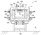
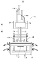
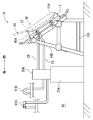
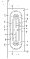
- FIG. 10 It is a front view showing fixture 10 concerning Embodiment 1 of the present invention. It is a top view showing the fixture 10 of FIG. It is a left side view showing mounting tool 10 of Drawing 1A. It is an IV line enlarged arrow view of FIG. FIG. 5 is an end view taken along line V-V of FIG. 4; FIG. 6 is an end elevation similar to FIG. 5 representing a third state of the invention.
- FIG. 10 It is a front view showing the embodiment which remodeled the fixture 10 of FIG.
- It is a front view showing the fixture 30 concerning Embodiment 2 of this invention.
- FIG. 10 is a left side view of the fixture 30 of FIG. 9; It is the XII line enlarged arrow view of FIG.
- FIG. 13 is an end view taken along line XIII-XIII of FIG. 12; It is an end elevation similar to FIG.
- this fixture 10 sets a plate-like work (for example, the front door panel 90 of a car) in an inclined state, and performs predetermined processing on this work (for example, a process for folding the edge of the front door panel 90) ) Is possible.
- a plate-like work for example, the front door panel 90 of a car
- predetermined processing on this work for example, a process for folding the edge of the front door panel 90
- the fixture 10 is arrange
- the pressure of the compressed air supplied by the air pressure source 91A is set to be smaller than the pressure of the compressed air supplied by the air pressure source 91B.
- the mounting tool 10 abuts on the front door panel 90 set as a work against the plate surface 90 A along the plate surface 90 A of the front door panel 90, thereby the front door panel 90.
- the support 11 is formed in a rectangular frame shape (see FIGS. 1 and 2) having a through hole 11A at the center, and only a portion of the plate surface 90A of the front door panel 90 which becomes an edge portion of the front door panel 90. It comes in contact with the
- the fixture 10 is rigidly joined to the leg 10A exhibiting a two-layer one-span three-dimensional rigid frame structure and the upper rim of the three-dimensional rigid frame structure of the leg 10A. And two provided in-arms 10B. As shown in FIG. 2 and FIG. 3, these combination palms 10 B are formed by combining two climbing ridges into a mountain shape and rigidly joining them, and the support 11 is attached to one of these climbing ridges in an inclined state Be As a result, as shown in FIG. 3, the support 11 brings the front door panel 90 in contact with the support 11 into an inclined state.
- the legs 10A collectively support the weight of the two doubled palms 10B and the load applied to the doubled palms 10B (for example, the load received from the front door panel 90).
- the side (the right side in FIG. 3) to which the support 11 is attached in the joined palm 10B of the mounting tool 10 is referred to as the “front side” of the mounting tool 10 and the side opposite the front side (the left side in FIG. 3) Will be described as the “rear side” of the fixture 10.
- the fixture 10 is provided with a rectangular parallelepiped casing 20A on the rear side of the leg 10A.
- the housing 20A is placed on a remote control type control unit 23A installed on the floor of the facility 91. Further, air pressure sources 91A and 91B of the facility 91 are connected to the rear side of the housing 20A.
- the control unit 23A controls the operation of the electric actuator 23B by controlling the electric energy supplied to the electric actuator 23B (see FIG. 7) housed in the housing 20A.
- the pad 12 faces the side of the support 11 in contact with the plate surface 90A of the front door panel 90 at the inner edge on the upper side of the rectangular frame. It is attached.
- the pad 12 has a configuration in which an elastomeric lip 12A protrudes annularly from the surface of a metal base 12B.
- the pad 12 can be made to contact
- the pad 12 can be brought into contact with the surface 90A of the front door panel 90.
- the lip portion 12A is inserted into the groove 12D formed in the base portion 12B in the shape of an oval ring (see FIG. 4), and the projecting portion 12J protrudes uniformly from the surface of the base portion 12B.
- the base portion 12B is formed such that an area 12C inside the ring (see FIG. 4) formed by the lip portion 12A in the base portion 12B is planar.
- the pad 12 is provided with a first suction passage 24 and a second suction passage 25 which are separately opened in the area 12C of the base portion 12B.
- the second suction passage 25 has one end opened at the central portion of the oval in the area 12C (see the opening 25B in FIG. 4) and the other end opened in the casing 20A (FIG. 7). Reference).
- the first suction passage 24 is a bifurcated bifurcated pipe (see FIG. 7) bifurcated in the pad 12 and the two ends on the bifurcated side have two openings in the area 12C. It is opened as 24B. As shown in FIGS. 4 and 5, these openings 24B are arranged so as to sandwich the opening 25B of the second suction passage 25 from both sides in the longitudinal direction of the area 12C (both left and right in FIG. 4).
- the end of the first suction passage 24 not open to the area 12C is a filter 24A (see FIG. 7) opened in the housing 20A.
- the pad 12 has a plurality of projections projecting from the area 12C to the side (upper side in FIG. 5) which is the side of the plate surface 90A of the front door panel 90 in the contact state.
- a unit 12H is provided.
- the projecting dimension (see the projecting dimension 12I in FIG. 5) from which the projecting portion 12H projects from the base portion 12B is made to be the same size in any portion of the projecting portion 12H.
- the protrusion dimension 12I of the protrusion 12H with respect to the base 12B is smaller than the protrusion dimension 12J of the lip 12A with respect to the base 12B.
- each of the projecting portions 12H forms a plurality (four in FIG. 4) of convex stripes extending in the longitudinal direction (left and right direction as viewed in FIG. 4) of the oval of the area 12C.
- the protrusion 12H is an elastomeric rectangular string fitted in a groove 12F formed linearly in the area 12C of the base 12B.
- the pad 12 is provided with two packing portions 12G which are protruded from the area 12C to the side of the front door panel 90 which is the side of the plate surface 90A in the contact state.
- the protrusion dimension (see the protrusion dimension 12K in FIG. 5) from which the packing portion 12G protrudes from the base portion 12B is made to be the same size at any portion in the packing portion 12G.
- the protrusion dimension 12I of the protrusion 12H with respect to the base 12B is larger than the protrusion dimension 12J of the lip 12A with respect to the base 12B.
- the packing portion 12G is disposed in such a manner as to surround the periphery of each of the two openings 24B in the area 12C.
- the packing portion 12G is an angular ring made of an elastomer fitted in a groove 12E formed annularly in the area 12C of the base portion 12B.
- the negative pressure unit 20 having the air pressure sources 91A and 91B as a power source is housed in the housing 20A of the fixture 10.
- the negative pressure unit 20 is provided with a rough suction device 21 which is constantly driven by a relatively low pressure air pressure source 91A and sucks air from the suction port 21A.
- the negative pressure unit 20 is provided with a main suction device 22 which is always driven by a relatively high pressure air pressure source 91B and sucks air from the suction port 22A with a suction force stronger than the rough suction device 21.
- the rough suction device 21 is an ejector pump provided with a silencer 21B.
- the main suction device 22 is an ejector pump provided with a silencer 22B.
- the negative pressure unit 20 includes the filter 24A of the first suction passage 24, the filter 25A of the second suction passage 25, the suction port 21A of the rough suction device 21, and the suction port 22A of the true suction device 22.
- a switching system 23 connected to each other.
- the switching system 23 has an electric actuator 23B, and in accordance with the operation of the electric actuator 23B, the connection states of the respective components connected to the switching system 23 will be described below (A) (B) (C) It is supposed to switch to any of the states).
- the electric actuator 23B operates in accordance with the operation of a remote control (not shown) of the control unit 23A. However, the electric actuator 23B can also be set to operate according to a robot program previously input to the control unit 23A.
- the method to perform desired processing to the front door panel 90 is demonstrated using the fixture 10 which has each structure mentioned above.
- the operator operates the remote control (not shown) of the control unit 23A in advance to switch the switching system 23 of the negative pressure unit 20 to the state of (A) described above. Switch on.
- This state is an abutting state in which both the suction of air via the first suction passage 24 and the suction of air via the second suction passage 25 are stopped, and the “first state” in the present invention It corresponds to
- the switching system 23 of the negative pressure unit 20 is switched from the state of (A) described above to the state of (B) described above.
- the negative pressure unit 20 starts suction of air through the first suction path 24 by the rough suction device 21, and the plate surface 90 A of the front door panel 90 and the packing portion 12 G of the pad 12 Negative pressure is applied in the enclosed space 90D (see FIG. 5).
- the packing portion 12G is deformed so as to be crushed by the atmospheric pressure applied to the front door panel 90 from the opposite side to the space 90D which is a negative pressure, as shown by an imaginary line in FIG. Then, the distance 90C between the base 12B of the pad 12 and the plate surface 90A of the front door panel 90 becomes short, and the lip 12A of the pad 12 abuts on the plate surface 90A of the front door panel 90.
- the negative pressure unit 20 brings the plate surface 90A of the front door panel 90 into a suction state where the plate surface 90A is suctioned to the pad 12.
- This state is an adsorption state in which air is sucked through the first suction passage 24 and the flow of air through the second suction passage 25 is stopped, and the “second state” in the present invention It corresponds to In other words, the negative pressure unit 20 switches from the first state to the second state.
- the front door panel 90 In the second state, since the suction force acting on the front door panel 90 is relatively weak, the front door panel 90 is temporarily fixed so as to be able to move in a shear on the support 11 of the fixture 10. Therefore, the operator can easily adjust the position of the front door panel 90 that has been temporarily fixed.
- a distance 90C between the plate surface 90A of the front door panel 90 and the base 12B of the pad 12 is a projection dimension 12I from which the projection 12H is projected from the base 12B (see FIG. 5) It will be longer than).
- the protrusion 12H of the pad 12 is positioned with a gap (see the phantom line in FIG. 6) with the plate surface 90A of the front door panel 90.
- the switching system 23 of the negative pressure unit 20 is switched to the state of (C) described above.
- the negative pressure unit 20 performs suction of air through the first suction passage 24 by the rough suction device 21 to suction of air through the second suction passage 25 by the real suction device 22. Switch. Then, the negative pressure unit 20 reduces the air pressure in the space 90B surrounded by the plate surface 90A of the front door panel 90 and the lip portion 12A of the pad 12 to a pressure lower than the air pressure in the space 90D.
- the negative pressure unit 20 brings the plate surface 90A of the front door panel 90 into a state of being attracted by the pad 12 with a relatively strong force.
- This state is an adsorption state where air is sucked through the second suction path 25 and the flow of air through the first suction path 24 is stopped, and the “third state” in the present invention It corresponds to In other words, the negative pressure unit 20 switches from the second state to the third state.
- the suction force acting on the front door panel 90 causes the front door panel 90 to be held stably with respect to the fixture 10. Then, the operator performs desired processing on the front door panel 90 in the holding state.
- the amount of deformation of the protrusion 12H due to the force received from the plate surface 90A of the front door panel 90 is as small as negligible.
- the protrusion 12H may be deformed (not shown) so as to be crushed by the plate surface 90A of the front door panel 90.
- the distance 90C between the base 12B of the pad 12 and the plate surface 90A of the front door panel 90 is a protrusion 12I (see FIG. 5) from which the protrusion 12H is projected from the base 12B. It becomes below.
- the switching system 23 of the negative pressure unit 20 is switched to the state of (A) described above.
- the filter 24A of the first suction passage 24 and the filter 25A of the second suction passage 25 are opened to the outside air, and the negative pressure in the space 90D and the space 90B disappears.
- the front door panel 90 can be freely removed from the fixture 10. Then, the operator removes the front door panel 90 from the fixture 10 to complete the operation.
- the fixture 10 described above is a switching system of the negative pressure unit 20 as to whether the front door panel 90 is adsorbed by the rough suction device 21 with relatively weak suction force or the main suction device 22 with relatively strong suction force. It can be switched by 23. Thereby, the state in which the front door panel 90 is adsorbed to the fixture 10 by the rough suction device 21 having a relatively weak suction force is maintained for a long time, and the position adjustment of the front door panel 90 is performed while this state is maintained. It becomes easy to do.
- the fixture 10 stops the flow of air through the first suction passage 24.
- air can be sucked from the first suction passage 24 and the suction force of the front door panel 90 can be prevented from being weakened.
- the mounting tool 10 sucks the front door panel 90 by the suction device 22 having a relatively strong suction force, air is sucked from the first suction passage 24 of the packing portion 12G of the pad 12. It can function as a packing to avoid
- the protrusion 12H of the pad 12 can function as a spacer. This prevents the negative pressure from bending the front door panel 90 and the bending of the front door panel 90 from collapsing the space 90 B where suction is performed.
- the mounting tool 10 sucks the front door panel 90 by the rough suction device 21 which has a relatively weak suction force, there is a clearance between the protrusion 12H of the pad 12 and the plate surface 90A of the front door panel 90. Position on Thus, the protrusion 12H of the pad 12 can be prevented from interfering with the suction of air by the rough suction device 21.
- Embodiment 2 which is one of the embodiments for implementing this invention is demonstrated using drawing.
- the fixture 30 is a modification of the fixture 10 according to the first embodiment described above. Therefore, about the composition which is common with each composition of the above-mentioned fitting 10 in fitting 30, the code which added "20" to the code attached to these each composition is made to correspond, and the detailed explanation is omitted. .
- the fixture 30 is, as shown in FIGS. 9 to 11, an oil rotary vacuum having a rotational speed control function instead of the negative pressure unit 20 (see FIG. 7) powered by two pneumatic pressure sources 91A and 91B.
- a negative pressure unit 40 consisting of a pump is provided.
- the negative pressure unit 40 changes the rotational speed of the oil rotary vacuum pump to suck air at a relatively weak negative pressure, suck air at a relatively strong negative pressure, and air It is possible to switch to the stop state where the suction is not performed.
- the negative pressure unit 40 is provided with only one suction passage 45 for suctioning air. That is, in place of the pad 12 (see FIG. 5), which allows both suction of air through the first suction passage 24 and suction of air through the second suction passage 25, the fixture 30 can be used.
- a pad 32 capable of suctioning air via a suction passage 45 is provided.
- the pad 32 does not have a configuration corresponding to the opening 24B and the packing portion 12G (see FIG. 4) provided in the pad 12 as shown in FIGS. 12 to 14.
- the pad 32 is provided so as to border the base portion 32B, and is a skirt portion which is projected to surround the ring formed by the lip portion 32A. 32E is provided.
- the skirt portion 32E is configured to be flexible but not breathable (for example, a closed-cell rubber sponge).
- the skirt portion 32E is provided with an end edge portion 32G which is formed in a strip shape which can be largely reduced against an external force.
- the edge portion 32G is on the side of the plate surface 90A (upper side in FIG. 13) in the contact state (see the imaginary line in FIG. 13) in which the pad 32 is in contact with the plate surface 90A of the front door panel 90. It is protruded in the state where it was inclined toward the outside of.
- the skirt portion 32E has flexibility to allow the end edge portion 32G to move in the direction along the surface of the base portion 32B (in the left and right direction in FIG. 13).
- a projecting dimension 32K in which the end edge portion 32G of the skirt portion 32E is projected from the base portion 32B is larger than a projecting dimension 32J in which the lip portion 32A is projected from the base portion 32B.
- the negative pressure unit 40 is switched from the stop state to a state where suction of air is performed with relatively weak negative pressure, and a space 90D surrounded by the plate surface 90A of the front door panel 90 and the skirt portion 32E of the pad 32 (see FIG. Make negative pressure in the inside).
- the end edge 32G of the skirt portion 32E is deformed so as not to be pushed by the atmospheric pressure applied to the front door panel 90 from the opposite side to the space 90D which is a negative pressure, as shown by an imaginary line in FIG. Do.
- the negative pressure unit 40 brings the plate surface 90A of the front door panel 90 into a suction state where the plate surface 90A is sucked by the pad 32.
- This state corresponds to the "roughing state" in the present invention, and the distance 90C between the base portion 32B and the plate surface 90A of the front door panel 90 in the roughing state is smaller than the above-described projecting dimension 32K.
- the distortion of the edge portion 32G of the skirt portion 32E is negligibly small compared with the proportional limit of the skirt portion 32E.
- the front door panel 90 is temporarily fixed so as to be movable in the direction along the surface of the base portion 32B (horizontal direction in FIG. 13) within the elastic limit of the skirt portion 32E while maintaining the suctioned state. . Therefore, the operator can easily adjust the position of the front door panel 90 in the temporarily fixed state.
- the force applied to the front door panel 90 is a force applied by switching the negative pressure unit 40 to a state where suction of air is performed with a relatively strong negative pressure, even if the operator applies the pressure by pressing the front door panel 90. It may be.
- the operator performs desired processing on the front door panel 90.
- the suction force acting on the front door panel 90 is insufficient to hold the front door panel 90 stably to the fixture 30, the operator strongly strengthens the negative pressure generated by the negative pressure unit 40. Operations can be performed. Therefore, the operator brings the front door panel 90 to the fixture 30 in the main pulling state (see the phantom line in FIG. 14) that achieves the suction state of the front door panel 90 with a relatively strong negative pressure by the negative pressure unit 40.
- a stable holding state can be achieved.
- the operator switches the negative pressure unit 40 to the stop state.
- the suction path 45 is opened to the outside air, and the negative pressure in the space 90D disappears.
- the front door panel 90 can be freely removed from the fixture 30. Then, the operator removes the front door panel 90 from the fixture 30 to complete the operation.
- the negative pressure unit 40 can switch whether the front door panel 90 is attracted by the attachment 30 described above, which is a rough pulling state in which the suction force is relatively weak or a main pulling state in which the suction force is relatively strong. As a result, the state in which the front door panel 90 is adsorbed to the fixture 30 is maintained for a long time due to the rough pulling state where the suction force is relatively weak, and the position adjustment of the front door panel 90 is facilitated while this state is maintained. It will be possible to do.
- the attachment 30 attracts the front door panel 90 in a rough pull state where the suction force is relatively weak
- the front door panel within the elastic limit of the skirt portion 32E while maintaining the adsorbed state. 90 can be moved in the direction along the surface of the base 32B.
- the operator can easily adjust the position of the front door panel 90 that has been temporarily fixed.
- the fixture 10 shown in FIGS. 1 to 3 has its support 11 formed in the shape of a rectangular frame, and has only one pad 12 at the upper inner edge of the rectangular frame.
- the number and arrangement of the pads provided on the fixture can vary.
- a total of four pads 12 are arranged at each edge of the rectangular frame support 11.
- the shape and size of the support provided in the fixture can be changed in accordance with the material, shape, size, etc. of the work set in the fixture.
- the rough suction device and the suction device of the negative pressure unit are not limited to the ejector pump driven by the pneumatic pressure source that supplies compressed air of different pressures. That is, for example, the rough suction device is an oil rotary pump, and the main suction device is a pump assembly incorporating a mechanical booster pump, etc., thereby changing a specific device used as a rough suction device or a main suction device. be able to.
- the number and specific shape of the protrusions provided in the area inside the ring formed by the lip can be changed. Also, one or both of these protrusions or packing may be omitted from the pad of the fixture.
- the fixture 30 shown in FIG. 9 has a skirt 32E whose pad 32 has a non-breathable configuration.
- a configuration in which air leaks out can be employed.
- This configuration may be, for example, a hole or a gap set on the periphery of the skirt bordering the base, or an incomplete seal between the base and the skirt.
- the negative pressure generated by the negative pressure unit is weakened by the leakage of air from the skirt portion and works on the work. The power is reduced.
Landscapes
- Engineering & Computer Science (AREA)
- Mechanical Engineering (AREA)
- Robotics (AREA)
- Manipulator (AREA)
- Jigs For Machine Tools (AREA)
Abstract
取付具(10)は、フロントドアパネル(90)(ワーク)を傾斜状態に支持する支持体(11)、フロントドアパネル(90)の板面(90A)に当接可能なパッド(12)、パッド(12)がフロントドアパネル(90)の板面(90A)に当接された状態において、この板面(90A)とパッド(12)とで囲まれるスペース内を負圧にしてフロントドアパネル(90)の板面(90A)を吸着状態にする負圧ユニット(20)を備える。この負圧ユニット(20)は、上記吸着状態を実現しない停止状態と、負圧を比較的弱くした状態で上記吸着状態を実現するあら引き状態と、上記負圧を比較的強くした状態で上記吸着状態を実現する本引き状態と、の切り替えが可能である。
Description
本発明は、板状のワークを傾斜状態にセットすることが可能な取付具に関する。
従来、板状のワークを加工する際に、このワークを取付具に傾斜状態にセットすることが行われている。この取付具に関しては、例えば特開2004-179472号公報に記載された技術が知られている。この技術では、ワークを傾斜状態に支持する支持体に開けられた貫通孔内に空気を吸引する吸着部材を配して、その吸引力により手などで押さえた状態のワークを取付具に吸着させる。ここで、ワークは、吸着部材による空気の吸引開始後しばらくの間は比較的弱い力で取付具に吸着され、吸着部材による空気の吸引を続けるとより強い力で取付具に吸着固定される。
特開2004-179472号公報に記載された従来の技術においては、空気の吸引を続ける吸着部材がその吸引力によりワークに向かって動いてこのワークと密接することで、ワークが強い力で取付具に吸着固定された状態となる。したがって、上記従来の技術においては、ワークが、このワークの位置調整を容易に行うことが可能な比較的弱い力で取付具に吸着された状態を維持することが難しいという課題があった。
本発明の1つの特徴によると、板状のワークを傾斜状態にセットすることが可能な取付具が提供される。この取付具は、ワークの板面に沿ってこの板面に当接することで、セットされたワークを傾斜状態に支持する支持体を備えている。また、取付具は、ベース部とこのベース部の表面に環状に突出されたリップ部とを有し、このリップ部を支持体に支持された状態のワークの板面に当接させることが可能とされたパッドを備えている。また、取付具は、パッドがワークの板面に当接された当接状態において、この板面とパッドとで囲まれるスペース内を負圧にすることで、ワークの板面をパッドに吸着された吸着状態にする負圧ユニットを備えている。この負圧ユニットは、上記吸着状態を実現しない停止状態と、負圧を比較的弱くした状態で上記吸着状態を実現するあら引き状態と、上記負圧を比較的強くした状態で上記吸着状態を実現する本引き状態と、の切り替えが可能とされている。
以下に、本発明を実施するための実施形態の1つである実施形態1にかかる取付具10について、図面を用いて説明する。この取付具10は、図3に示すように、板状のワーク(例えば車のフロントドアパネル90)を傾斜状態にセットして、このワークに対する所定の加工(例えばフロントドアパネル90の縁部を折り返す加工)を可能とするものである。
取付具10は、図1ないし図3に示すように、複数の空圧源91A、91Bが配備された施設91に配設される。これらの空圧源91A、91Bは、それぞれ異なる圧力の圧縮空気を導管により供給するものである。ここで、空圧源91Aが供給する圧縮空気の圧力は、空圧源91Bにより供給される圧縮空気の圧力よりも小さくなるように設定されている。
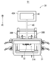
また、取付具10は、図3に示すように、ワークとしてセットされたフロントドアパネル90に対して、このフロントドアパネル90の板面90Aに沿ってこの板面90Aに当接することで、フロントドアパネル90を下側から支持する支持体11を備えている。この支持体11は、中央に貫通孔11Aを備えた方形枠状(図1および図2を参照)に形成されて、フロントドアパネル90の板面90Aのうちフロントドアパネル90の縁部となる部分のみに当接するようになっている。
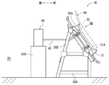
また、取付具10は、図1および図3に示すように、2層1スパンの立体ラーメン構造を呈する脚部10Aと、この脚部10Aの立体ラーメン構造の上縁に剛接合された状態に設けられた2つの合掌10Bとを備えている。これらの合掌10Bは、図2および図3に示すように、2本の登りばりを山形に組み合わせて剛接合させたものであり、これらの登りばりの一方に支持体11が傾いた状態に取り付けられる。これにより、支持体11は、図3に示すように、この支持体11に当接するフロントドアパネル90を、傾斜状態にセットされた状態とする。
また、脚部10Aは、図3に示すように、2つの合掌10Bの重量およびこれらの合掌10Bにかかる荷重(例えばフロントドアパネル90から受ける荷重)をまとめて支持する。なお、以下においては、取付具10の合掌10Bにおいて支持体11が取り付けられる側(図3では右側)を取付具10の「前側」とし、この前側とは反対となる側(図3では左側)を取付具10の「後側」として説明を行う。
また、取付具10は、その脚部10Aの後側に直方体状のきょう体20Aを備えている。このきょう体20Aは、施設91の床の上に設置されたリモコン式のコントロールユニット23Aの上に載せられた状態とされている。また、きょう体20Aにおいて後側となる面には、施設91の空圧源91A、91Bがそれぞれ接続されている。ここで、コントロールユニット23Aは、きょう体20Aの中に収納された電気アクチュエーター23B(図7参照)に供給される電気エネルギーをコントロールすることで、この電気アクチュエーター23Bの動作を制御するものである。
ところで、合掌10Bにより傾いた状態に支持される支持体11には、その方形枠において上側となる内縁部に、支持体11においてフロントドアパネル90の板面90Aに当接する側を向けてパッド12が取り付けられている。このパッド12は、図1および図4に示すように、金属製のベース部12Bの表面からエラストマー製のリップ部12Aを環状に突出させた構成を有している。
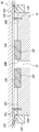
そして、パッド12は、図6に示すように、そのリップ部12Aを支持体11が支持するフロントドアパネル90の板面90Aに当接させることができるようになっている。言いかえると、パッド12は、フロントドアパネル90の板面90Aに当接された当接状態とすることが可能とされている。なお、本実施形態においては、リップ部12Aは、ベース部12Bに長円の環状(図4参照)に形成された溝12Dにはめ込まれて、ベース部12Bの表面から一様な突出寸法12J(図5参照)で突出されたエラストマー製の角リングである。また、ベース部12Bは、このベース部12Bにおいてリップ部12Aがなす環(図4参照)の内側となるエリア12Cが平面状となるように形成されている。
また、パッド12には、そのベース部12Bのエリア12Cにそれぞれ別個に開口された第1の吸引路24と第2の吸引路25とが設けられている。この第2の吸引路25は、その一端がエリア12Cの長円における中心部分に開口され(図4の開口25Bを参照)、その他端がきょう体20A内にて開口されたフィルター25A(図7参照)とされている。
また、第1の吸引路24は、パッド12内において二叉に分岐された二叉分岐管(図7参照)であり、分岐された側にある2つの端部は、エリア12Cにおいて2つの開口24Bとして開口されている。これらの開口24Bは、図4および図5に示すように、エリア12Cの長手方向両側(図4では左右両側)から第2の吸引路25の開口25Bを挟み込むように配置されている。また、第1の吸引路24においてエリア12Cに開口されない側の端部は、きょう体20A内にて開口されたフィルター24A(図7参照)とされている。
また、パッド12には、図5および図6に示すように、そのエリア12Cから上記当接状態においてフロントドアパネル90の板面90A側となる側(図5では上側)に突出された複数の突出部12Hが設けられている。ここで、突出部12Hがベース部12Bから突出される突出寸法(図5の突出寸法12Iを参照)は、突出部12Hにおけるどの部分においても同じ大きさとなるようにされている。なお、図5に示すように、ベース部12Bに対する突出部12Hの突出寸法12Iは、ベース部12Bに対するリップ部12Aの突出寸法12Jよりも小さい。
また、突出部12Hは、図4に示すように、それぞれがエリア12Cの長円の長手方向(図4で見て左右方向)に伸びる複数本(図4では4本)の凸条をなすように配設されている。本実施形態においては、突出部12Hは、ベース部12Bのエリア12Cに直線状に形成された溝12Fにはめ込まれたエラストマー製の角ひもである。
また、パッド12には、図5および図6に示すように、そのエリア12Cから上記当接状態においてフロントドアパネル90の板面90A側となる側に突出された2つのパッキン部12Gが設けられている。ここで、パッキン部12Gがベース部12Bから突出される突出寸法(図5の突出寸法12Kを参照)は、パッキン部12Gにおけるどの部分においても同じ大きさとなるようにされている。なお、図5に示すように、ベース部12Bに対する突出部12Hの突出寸法12Iは、ベース部12Bに対するリップ部12Aの突出寸法12Jよりも大きい。
また、パッキン部12Gは、図4に示すように、エリア12Cにおける2つの開口24Bのそれぞれに対し、その周囲を取り囲んだ状態となるように配設されている。本実施形態においては、パッキン部12Gは、ベース部12Bのエリア12Cに円環状に形成された溝12Eにはめ込まれたエラストマー製の角リングである。
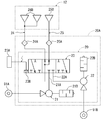
さて、取付具10のきょう体20Aの中には、図7に示すように、空圧源91A、91Bを動力源とした負圧ユニット20が収納されている。この負圧ユニット20は、比較的低圧の空圧源91Aにより常時駆動されて、吸引口21Aから空気を吸引するあら引き吸引装置21を備えている。また、負圧ユニット20は、比較的高圧の空圧源91Bにより常時駆動されて、あら引き吸引装置21よりも強い吸引力で吸引口22Aから空気を吸引する本引き吸引装置22を備えている。本実施形態においては、あら引き吸引装置21は、サイレンサー21Bが付設されたエジェクターポンプである。また、本引き吸引装置22は、サイレンサー22Bが付設されたエジェクターポンプである。
また、負圧ユニット20は、第1の吸引路24のフィルター24Aと、第2の吸引路25のフィルター25Aと、あら引き吸引装置21の吸引口21Aと、本引き吸引装置22の吸引口22Aとがそれぞれ接続された切り替えシステム23を備えている。この切り替えシステム23は、電気アクチュエーター23Bを有して、この電気アクチュエーター23Bの動作に応じて、切り替えシステム23に接続された各構成の接続状態を、以下に記載する(A)(B)(C)の状態のいずれかに切り替えるようになっている。
(A)吸引口21Aおよび吸引口22Aのそれぞれが閉塞され、フィルター24Aおよびフィルター25Aのそれぞれが外気に開放された状態。この状態においては、第1の吸引路24を介した空気の吸引および第2の吸引路25を介した空気の吸引の両方が停止される。これにより、負圧ユニット20は、パッド12のパッキン部12Gがフロントドアパネル90の板面90Aに当接した場合でもこの板面90Aを吸着状態としない停止状態となる。
(B)フィルター25Aおよび吸引口22Aのそれぞれが閉塞され、フィルター24Aと吸引口21Aとが接続された状態。この状態においては、あら引き吸引装置21は第1の吸引路24を介して空気を吸引する。また、第2の吸引路25を介した空気の吸引は停止される。このとき、負圧ユニット20におけるパッド12のパッキン部12Gがフロントドアパネル90の板面90Aに当接すると、この板面90Aが比較的弱い負圧で吸着状態とされるあら引き状態となる。
(C)吸引口21Aおよびフィルター24Aのそれぞれが閉塞され、フィルター25Aと吸引口22Aとが接続された状態。この状態においては、本引き吸引装置22は第2の吸引路25を介して空気を吸引する。また、第1の吸引路24を介した空気の吸引は停止される。このとき、負圧ユニット20におけるパッド12のパッキン部12Gがフロントドアパネル90の板面90Aに当接すると、この板面90Aが比較的強い負圧で吸着状態とされる本引き状態となる。
なお、電気アクチュエーター23Bは、コントロールユニット23Aのリモコン(図示せず)の操作に従って動作する。ただし、電気アクチュエーター23Bは、コントロールユニット23Aに前もって入力されたロボットプログラムに従って動作するように設定することもできる。
続いて、上述した各構成を有する取付具10を使用して、フロントドアパネル90に所望の加工を施す方法について説明する。取付具10の使用に際しては、オペレーター(図示せず)は、前もってコントロールユニット23Aのリモコン(図示せず)を操作することで、負圧ユニット20の切り替えシステム23を上述した(A)の状態に切り替えておく。
そして、オペレーターは、取付具10の支持体11にフロントドアパネル90を立てかけて、このフロントドアパネル90を取付具10に対して傾斜状態にセットされた状態にする。このとき、オペレーターは、フロントドアパネル90を手で押さえることで、パッド12のパッキン部12Gの全体がフロントドアパネル90の板面90Aに当接された当接状態(図5の仮想線を参照)を実現させる。この状態は、第1の吸引路24を介した空気の吸引および第2の吸引路25を介した空気の吸引の両方が停止された当接状態であり、本発明における「第1の状態」に相当する。
この後、負圧ユニット20の切り替えシステム23は、上述した(A)の状態から上述した(B)の状態へと切り替えられる。これに対して、負圧ユニット20は、あら引き吸引装置21による第1の吸引路24を介した空気の吸引を開始して、フロントドアパネル90の板面90Aとパッド12のパッキン部12Gとで囲まれるスペース90D(図5参照)内を負圧にする。
このとき、パッキン部12Gは、図6に仮想線で示すように、負圧となるスペース90Dとは反対側からフロントドアパネル90にかかる大気圧によって、押しつぶされるように変形する。そして、パッド12のベース部12Bとフロントドアパネル90の板面90Aとの距離90Cは短くなり、パッド12のリップ部12Aはフロントドアパネル90の板面90Aに当接する。
これにより、負圧ユニット20は、フロントドアパネル90の板面90Aをパッド12に吸着された吸着状態にする。この状態は、第1の吸引路24を介して空気が吸引され、かつ、第2の吸引路25を介した空気の流通が停止された吸着状態であり、本発明における「第2の状態」に相当する。言いかえると、負圧ユニット20は、上記第1の状態から上記第2の状態への切り替えを行う。
なお、上記第2の状態においてフロントドアパネル90にはたらく吸着力は比較的弱いため、フロントドアパネル90は、取付具10の支持体11上でずり動かすことが可能な仮固定状態となる。このため、オペレーターは、上記仮固定状態となったフロントドアパネル90の位置調整を容易に行うことができる。
また、上記第2の状態においては、パッド12のリップ部12Aにはたらく上記吸着力の反作用が比較的弱くなるため、この反作用によるリップ部12Aの変形量は無視できるほど小さくなる。このため、上記第2の状態においては、フロントドアパネル90の板面90Aとパッド12のベース部12Bとの距離90Cは、このベース部12Bから突出部12Hが突出される突出寸法12I(図5参照)よりも長くなる。言いかえると、上記第2の状態においては、パッド12の突出部12Hがフロントドアパネル90の板面90Aとの間に隙間を有する状態(図6の仮想線を参照)に位置される。
さて、上記第2の状態においてフロントドアパネル90の位置調整が適宜に行われた後、負圧ユニット20の切り替えシステム23は、上述した(C)の状態に切り替えられる。これに対して、負圧ユニット20は、あら引き吸引装置21による第1の吸引路24を介した空気の吸引を、本引き吸引装置22による第2の吸引路25を介した空気の吸引に切り替える。そして、負圧ユニット20は、フロントドアパネル90の板面90Aとパッド12のリップ部12Aとで囲まれるスペース90B内の気圧を、スペース90D内の気圧よりもさらに低い気圧に低下させる。
これにより、負圧ユニット20は、フロントドアパネル90の板面90Aをパッド12に比較的強い力で吸着された吸着状態にする。この状態は、第2の吸引路25を介して空気が吸引され、かつ、第1の吸引路24を介した空気の流通が停止された吸着状態であり、本発明における「第3の状態」に相当する。言いかえると、負圧ユニット20は、上記第2の状態から上記第3の状態への切り替えを行う。
なお、上記第3の状態においてフロントドアパネル90にはたらく吸着力は、このフロントドアパネル90を取付具10に対して安定的に保持された保持状態とする。そして、オペレーターは、上記保持状態となったフロントドアパネル90に対して所望の加工を施す。
また、上記第3の状態においては、パッド12のリップ部12Aにはたらく上記吸着力の反作用が比較的強くなるため、この反作用によりリップ部12Aは押しつぶされるように変形する(図6の実線を参照)。このため、上記第2の状態から上記第3の状態への切り替えに伴って、パッド12のベース部12Bとフロントドアパネル90の板面90Aとの距離90Cは短くなり、突出部12Hはフロントドアパネル90の板面90Aに当接してこの板面90Aを支持する(図6の実線を参照)。ここで、パッキン部12Gは、開口24Bの周囲を取り囲んでいるため、この周囲のスペース90Bと開口24Bとの間の空気の流通を遮断する。
ここで、図6においては、フロントドアパネル90の板面90Aから受ける力による突出部12Hの変形量は無視できるほど小さいものとなっている。しかしながら、上記第3の状態において、突出部12Hは、フロントドアパネル90の板面90Aによって押しつぶされるように変形する(図示省略)可能性があるものである。言いかえると、パッド12のベース部12Bとフロントドアパネル90の板面90Aとの距離90Cは、上記第3の状態において、ベース部12Bから突出部12Hが突出される突出寸法12I(図5参照)以下となる。
ところで、上記第3の状態においてフロントドアパネル90に対して所望の加工が施された後、負圧ユニット20の切り替えシステム23は、上述した(A)の状態に切り替えられる。このとき、第1の吸引路24のフィルター24Aと、第2の吸引路25のフィルター25Aとはそれぞれが外気に開放され、スペース90D内およびスペース90B内の負圧はなくなる。これにより、フロントドアパネル90は、取付具10から自由に取り外すことができる状態になる。そして、オペレーターは、フロントドアパネル90を取付具10から取り外して作業を終了させる。
上述した取付具10は、比較的吸引力が弱いあら引き吸引装置21または比較的吸引力が強い本引き吸引装置22のいずれによってフロントドアパネル90が吸着されるかを、負圧ユニット20の切り替えシステム23により切り替えることができる。これにより、比較的吸引力が弱いあら引き吸引装置21によりフロントドアパネル90が取付具10に吸着された状態を長時間維持して、この状態が維持されている間にフロントドアパネル90の位置調整を容易に行うことが可能となる。
また、取付具10は、比較的吸引力が強い本引き吸引装置22によりフロントドアパネル90の吸着が行われているときに、第1の吸引路24を介した空気の流通を停止させる。これにより、この第1の吸引路24から空気が吸引されてフロントドアパネル90の吸着力が弱まることをさけることができる。また、取付具10は、比較的吸引力が強い本引き吸引装置22によるフロントドアパネル90の吸着を行う際に、パッド12のパッキン部12Gを、第1の吸引路24から空気が吸引されることをさけるためのパッキンとして機能させることができる。
また、取付具10は、比較的吸引力が強い本引き吸引装置22によるフロントドアパネル90の吸着を行う際に、パッド12の突出部12Hをスペーサーとして機能させることができる。これにより、負圧によりフロントドアパネル90がたわむこと、および、このフロントドアパネル90のたわみにより吸引が行われるスペース90Bがつぶれることをさけることができる。また、取付具10は、比較的吸引力が弱いあら引き吸引装置21によるフロントドアパネル90の吸着を行うときには、パッド12の突出部12Hをフロントドアパネル90の板面90Aとの間に隙間を有する状態に位置させる。これにより、パッド12の突出部12Hがあら引き吸引装置21による空気の吸引を妨げることをさけることができる。
続いて、本発明を実施するための実施形態の1つである実施形態2にかかる取付具30について、図面を用いて説明する。この取付具30は、上述した実施形態1にかかる取付具10を改造したものである。したがって、取付具30において上記取付具10の各構成と共通する構成については、これらの各構成に付した符号に「20」を加算した符号を付して対応させ、その詳細な説明を省略する。
取付具30は、図9ないし図11に示すように、2つの空圧源91A、91Bを動力源とする負圧ユニット20(図7参照)の代わりに、回転数制御機能を有する油回転真空ポンプからなる負圧ユニット40を備えている。この負圧ユニット40は、その油回転真空ポンプの回転数を変更することで、比較的弱い負圧で空気の吸引を行う状態と、比較的強い負圧で空気の吸引を行う状態と、空気の吸引を行わない停止状態とに切り替えることが可能とされている。
ここで、負圧ユニット40は、空気の吸引を行うための吸引路45を1本だけ備えている。すなわち、取付具30は、第1の吸引路24を介した空気の吸引および第2の吸引路25を介した空気の吸引の両方が可能とされたパッド12(図5参照)の代わりに、吸引路45を介した空気の吸引が可能とされたパッド32を備えている。このパッド32は、図12ないし図14に示すように、パッド12に設けられた開口24Bおよびパッキン部12G(図4参照)に相当する構成を備えていない。
また、パッド32には、図12および図13に示すように、ベース部32Bを縁取るように設けられて、リップ部32Aがなす環の周囲を取り囲んだ状態となるように突出されたスカート部32Eが設けられている。このスカート部32Eは、可とう性を有するが通気性は有さない構成(例えば独立気泡ゴムスポンジ)とされている。
また、スカート部32Eは、外力に対して大きくしなうことができる帯状に形成された端縁部32Gを備えている。この端縁部32Gは、フロントドアパネル90の板面90Aにパッド32が当接された当接状態(図13の仮想線を参照)における板面90A側(図13では上側)に、ベース部32Bの外側に向けて傾いた状態で突出される。これにより、スカート部32Eには、その端縁部32Gがベース部32Bの表面に沿う方向(図13では左右方向)に移動することを許容する可とう性が担保される。なお、スカート部32Eの端縁部32Gがベース部32Bから突出される突出寸法32Kは、リップ部32Aがベース部32Bから突出される突出寸法32Jよりも大きい。
続いて、上述した各構成を有する取付具30を使用して、フロントドアパネル90に所望の加工を施す方法について説明する。取付具30の使用に際しては、オペレーター(図示せず)は、前もってコントロールユニット43Aのリモコン(図示せず)を操作することで、負圧ユニット40を停止状態に切り替えておく。
そして、オペレーターは、取付具30の支持体31にフロントドアパネル90を立てかけて、このフロントドアパネル90を取付具30に対して傾斜状態にセットされた状態にする。このとき、パッド32は、その端縁部32Gにおいてフロントドアパネル90の板面90Aに当接する。
この後、負圧ユニット40は、停止状態から比較的弱い負圧で空気の吸引を行う状態へと切り替えられ、フロントドアパネル90の板面90Aとパッド32のスカート部32Eとで囲まれるスペース90D(図13参照)内を負圧にする。このとき、スカート部32Eの端縁部32Gは、図13に仮想線で示すように、負圧となるスペース90Dとは反対側からフロントドアパネル90にかかる大気圧に押されて、しなうように変形する。これにより、パッド32のベース部32Bとフロントドアパネル90の板面90Aとの距離90Cは短くなるが、端縁部32Gの弾発力により、パッド32のリップ部32Aとフロントドアパネル90の板面90Aとは離間された状態を維持する。
これにより、負圧ユニット40は、フロントドアパネル90の板面90Aをパッド32に吸着された吸着状態にする。この状態は、本発明における「あら引き状態」に相当し、このあら引き状態におけるベース部32Bとフロントドアパネル90の板面90Aとの距離90Cは、上述した突出寸法32Kよりも小さくなる。また、あら引き状態においては、スカート部32Eの端縁部32Gのひずみはスカート部32Eの比例限度と比して無視できるほど小さい。このため、フロントドアパネル90は、その吸着状態を維持したまま、スカート部32Eの弾性限度の範囲内でベース部32Bの表面に沿う方向(図13では左右方向)に移動可能な仮固定状態となる。したがって、オペレーターは、上記仮固定状態となったフロントドアパネル90の位置調整を容易に行うことができる。
上記あら引き状態においてフロントドアパネル90の位置調整が適宜に行われた後、このフロントドアパネル90には、パッド32のベース部32Bに向かう向き(図14では下向き)の力がかけられる。これにより、パッド12のリップ部32Aは、その全体がフロントドアパネル90の板面90Aに当接された当接状態(図14の実線を参照)となり、フロントドアパネル90がベース部32Bの表面に沿う方向に移動することを抑制する。なお、フロントドアパネル90にかけられる力は、オペレーターがフロントドアパネル90を押さえつけることでかけられる力であっても、負圧ユニット40を比較的強い負圧で空気の吸引を行う状態に切り替えることでかけられる力であってもよい。
しかる後に、オペレーターは、フロントドアパネル90に対して所望の加工を施す。このとき、フロントドアパネル90にはたらく吸着力が、このフロントドアパネル90を取付具30に対して安定的に保持させるには力不足である場合、オペレーターは、負圧ユニット40が生じさせる負圧を強くする操作を行うことができる。したがって、オペレーターは、負圧ユニット40により、比較的強い負圧でフロントドアパネル90の吸着状態を実現する本引き状態(図14の仮想線を参照)とし、このフロントドアパネル90を取付具30に対して安定的に保持された保持状態とすることができる。
フロントドアパネル90に対して所望の加工が施された後、オペレーターは、負圧ユニット40を停止状態に切り替える。このとき、吸引路45は外気に開放され、スペース90D内の負圧はなくなる。これにより、フロントドアパネル90は、取付具30から自由に取り外すことができる状態になる。そして、オペレーターは、フロントドアパネル90を取付具30から取り外して作業を終了させる。
上述した取付具30は、比較的吸引力が弱いあら引き状態または比較的吸引力が強い本引き状態のいずれによってフロントドアパネル90が吸着されるかを、負圧ユニット40により切り替えることができる。これにより、比較的吸引力が弱いあら引き状態によりフロントドアパネル90が取付具30に吸着された状態を長時間維持して、この状態が維持されている間にフロントドアパネル90の位置調整を容易に行うことが可能となる。
また、取付具30は、比較的吸引力が弱いあら引き状態でフロントドアパネル90の吸着が行われているときに、その吸着状態を維持したまま、スカート部32Eの弾性限度の範囲内でフロントドアパネル90をベース部32Bの表面に沿う方向に移動させることができる。これにより、オペレーターは、上記仮固定状態となったフロントドアパネル90の位置調整を容易に行うことができる。
以上、本発明を実施するための形態について、上述した実施形態1および実施形態2によって説明した。しかしながら、当業者であれば、本発明の目的を逸脱することなく種々の代用、手直し、変更が可能であることは明らかである。すなわち、本発明を実施するための形態は、本明細書に添付した請求の範囲の精神および目的を逸脱しない全ての代用、手直し、変更を含みうるものである。例えば、本発明を実施するための形態として、以下のような各種の形態を実施することができる。
(1)図1ないし図3に示す取付具10は、その支持体11が方形枠状に形成されて、この方形枠において上側となる内縁部に、パッド12を1つだけ有するものである。しかしながら、取付具に設けられるパッドの数および配置は変更することができるものである。ここで、図8に示された、取付具10を改造した実施形態では、合計4つのパッド12が、方形枠をなす支持体11の各縁部に配置されている。また、取付具に設けられる支持体の形状およびサイズは、取付具にセットされるワークの材質、形状およびサイズなどにあわせて変更できるものである。
(2)負圧ユニットのあら引き吸引装置および本引き吸引装置は、それぞれ異なる圧力の圧縮空気を供給する空圧源により駆動されるエジェクターポンプに限定されない。すなわち、例えばあら引き吸引装置を油回転ポンプとし、本引き吸引装置をメカニカルブースターポンプが組み込まれたポンプアッセンブリとするなど、あら引き吸引装置または本引き吸引装置として用いられる具体的な装置を変更することができる。
(3)取付具のパッドにおいて、リップ部がなす環の内側となるエリアに設けられる突出部の数および具体的な形状は、変更することができる。また、これらの突出部あるいはパッキン部の一方もしくは両方を取付具のパッドから省略することもできる。
(4)図9に示す取付具30は、そのパッド32が通気性のない構成のスカート部32Eを有するものである。しかしながら、取付具のパッドがスカート部を有するものである場合、このスカート部に空気の漏れ出しが生じる構成を採用することができる。この構成は、例えばベース部を縁取るスカート部の周上に設定された孔あるいは隙間であっても、ベース部とスカート部との間のシールを不完全にしたものであってもよい。この構成によれば、スカート部に当接するワークの板面がリップ部から離間されている間、負圧ユニットが発生させる負圧がスカート部からの空気の漏れ出しによって弱められ、ワークにはたらく吸着力が小さくなる。また、ワークの板面がリップ部に当接すると、上記スカート部からの空気の漏れ出しの影響がなくなってワークにはたらく吸着力が大きくなる。したがって、出力の制御ができない構造の負圧ユニットを用いながら、この負圧ユニットに、比較的弱い負圧でワークを吸着するあら引き状態と、比較的強い負圧でワークを吸着する本引き状態と、の切り替えを実現させることができる。
Claims (6)
- 板状のワークを傾斜状態にセットすることが可能な取付具であって、
前記ワークの板面に沿って当該板面に当接することで、セットされた前記ワークを前記傾斜状態に支持する支持体と、
ベース部と当該ベース部の表面に環状に突出されたリップ部とを有し、当該リップ部を前記支持体に支持された状態の前記ワークの前記板面に当接させることが可能とされたパッドと、
前記パッドが前記ワークの前記板面に当接された当接状態において、当該板面と前記パッドとで囲まれるスペース内を負圧にすることで、前記ワークの前記板面を前記パッドに吸着された吸着状態にする負圧ユニットと、
を備え、
前記負圧ユニットは、前記吸着状態を実現しない停止状態と、前記負圧を比較的弱くした状態で前記吸着状態を実現するあら引き状態と、前記負圧を比較的強くした状態で前記吸着状態を実現する本引き状態と、の切り替えが可能とされている、
取付具。 - 請求項1に記載された取付具であって、
前記負圧ユニットは、
前記パッドの前記ベース部において前記リップ部がなす環の内側となるエリアに開口された第1の吸引路と接続されることで、当該第1の吸引路を介して空気を吸引するあら引き吸引装置と、
前記パッドの前記エリアに前記第1の吸引路とは別個に開口された第2の吸引路と接続されることで、当該第2の吸引路を介して前記あら引き吸引装置よりも強い吸引力で空気を吸引する本引き吸引装置と、
前記第1の吸引路を介した空気の吸引と前記第2の吸引路を介した空気の吸引との両方が停止された前記当接状態である第1の状態から、
前記第1の吸引路を介して空気が吸引され、かつ、前記第2の吸引路を介した空気の流通が停止された前記あら引き状態である第2の状態への切り替え、および、
当該第2の状態から、
前記第2の吸引路を介して空気が吸引され、かつ、前記第1の吸引路を介した空気の流通が停止された前記本引き状態である第3の状態への切り替えの両方を行う切り替えシステムと、
を備えている、
取付具。 - 請求項2に記載された取付具であって、
前記パッドは、前記第2の状態にあるときよりも前記第3の状態にあるときのほうが前記ベース部と前記ワークの前記板面との距離が短くなるように構成され、
前記パッドには、前記ベース部の前記エリアから前記当接状態において前記ワークの前記板面側となる側に突出された突出部が設けられ、
前記突出部は、当該突出部が前記ベース部から突出される突出寸法が、前記第2の状態における前記ベース部と前記ワークの前記板面との距離よりも短く、かつ、前記第3の状態における前記ベース部と前記ワークの前記板面との距離以上となるように形成されている、
取付具。 - 請求項2または請求項3に記載された取付具であって、
前記パッドには、前記ベース部の前記エリアから前記当接状態において前記ワークの前記板面側となる側に突出されたパッキン部が設けられ、
前記パッキン部は、当該パッキン部が前記ベース部から突出される突出寸法が前記第3の状態における前記ベース部と前記ワークの前記板面との距離以上となる状態、かつ、前記パッキン部が前記第1の吸引路における前記エリア内の開口の周囲を取り囲んだ状態となるように配設されている、
取付具。 - 請求項1に記載された取付具であって、
前記パッドには、前記ベース部から前記当接状態において前記ワークの前記板面側となる側に突出されたスカート部が、前記リップ部がなす環の周囲を取り囲んだ状態となるように設けられ、
前記スカート部は、当該スカート部が前記ベース部から突出される突出寸法が、前記あら引き状態における前記ベース部と前記ワークの前記板面との距離よりも大きくなる状態となるように配設されている、
取付具。 - 請求項5に記載された取付具であって、
前記スカート部において前記ベース部から突出される端縁部が前記ベース部の表面に沿う方向に移動することを許容する可とう性が前記スカート部に備えられている、
取付具。
Priority Applications (4)
| Application Number | Priority Date | Filing Date | Title |
|---|---|---|---|
| CN201880056520.0A CN111050991A (zh) | 2017-09-07 | 2018-08-08 | 固定装置 |
| JP2018560682A JP6692928B2 (ja) | 2017-09-07 | 2018-08-08 | 取付具 |
| US16/644,030 US20200346312A1 (en) | 2017-09-07 | 2018-08-08 | Fixture |
| EP18854556.0A EP3680061A4 (en) | 2017-09-07 | 2018-08-08 | FASTENING TOOL |
Applications Claiming Priority (2)
| Application Number | Priority Date | Filing Date | Title |
|---|---|---|---|
| JP2017-172116 | 2017-09-07 | ||
| JP2017172116 | 2017-09-07 |
Publications (1)
| Publication Number | Publication Date |
|---|---|
| WO2019049596A1 true WO2019049596A1 (ja) | 2019-03-14 |
Family
ID=65634005
Family Applications (1)
| Application Number | Title | Priority Date | Filing Date |
|---|---|---|---|
| PCT/JP2018/029819 Ceased WO2019049596A1 (ja) | 2017-09-07 | 2018-08-08 | 取付具 |
Country Status (5)
| Country | Link |
|---|---|
| US (1) | US20200346312A1 (ja) |
| EP (1) | EP3680061A4 (ja) |
| JP (1) | JP6692928B2 (ja) |
| CN (1) | CN111050991A (ja) |
| WO (1) | WO2019049596A1 (ja) |
Cited By (2)
| Publication number | Priority date | Publication date | Assignee | Title |
|---|---|---|---|---|
| IT202000017167A1 (it) * | 2020-07-15 | 2022-01-15 | Prussiani Eng S P A | Dispositivo di posizionamento e bloccaggio per materiale in lastra o parte di essa |
| JP2025080256A (ja) * | 2023-11-14 | 2025-05-26 | トライエンジニアリング株式会社 | 吸引パッド、加工装置および加工方法 |
Families Citing this family (3)
| Publication number | Priority date | Publication date | Assignee | Title |
|---|---|---|---|---|
| CN112296700B (zh) * | 2020-10-30 | 2021-09-21 | 永固集团股份有限公司 | 用于断路器零部件加工的吸附结构 |
| CN113070740B (zh) * | 2021-04-07 | 2023-05-30 | 昆明弘固机械制造有限公司 | 一种薄壁氧化铝陶瓷结构件的高效加工方法及负压夹具 |
| CN114887795B (zh) * | 2022-05-05 | 2025-12-05 | 兰州交通大学 | 一种基于高熵合金表面涂层用固定装置 |
Citations (5)
| Publication number | Priority date | Publication date | Assignee | Title |
|---|---|---|---|---|
| JPS62100835U (ja) * | 1985-12-16 | 1987-06-26 | ||
| JPS6364442U (ja) * | 1986-10-18 | 1988-04-28 | ||
| JP2004179472A (ja) | 2002-11-28 | 2004-06-24 | Noritake Co Ltd | ワーク固定装置 |
| WO2009081621A1 (ja) * | 2007-12-21 | 2009-07-02 | Mitsuboshi Diamond Industrial Co., Ltd. | レーザ加工装置およびレーザ加工方法 |
| JP2010142891A (ja) * | 2008-12-17 | 2010-07-01 | Linkstar Japan Co Ltd | 基板テーブルおよびそれを用いたレーザ加工装置 |
Family Cites Families (23)
| Publication number | Priority date | Publication date | Assignee | Title |
|---|---|---|---|---|
| JPS524979U (ja) * | 1975-06-24 | 1977-01-13 | ||
| US4527783A (en) * | 1983-04-26 | 1985-07-09 | Grumman Aerospace Corporation | Universal contoured parts holding fixture |
| JPH0638447B2 (ja) * | 1987-05-29 | 1994-05-18 | テラダイン株式会社 | ウエハ位置決め方法 |
| JPH01104796U (ja) * | 1987-12-30 | 1989-07-14 | ||
| JP2763261B2 (ja) * | 1993-12-21 | 1998-06-11 | セントラル硝子株式会社 | 吸着パッド |
| JPH081604A (ja) * | 1994-06-21 | 1996-01-09 | Marunaka Kakoki Kk | 木製パネル用吸着装置 |
| JPH0866841A (ja) * | 1994-08-25 | 1996-03-12 | Canon Inc | 物品の保持方法及びその装置 |
| JPH08197470A (ja) * | 1995-01-18 | 1996-08-06 | Toyota Auto Body Co Ltd | 真空吸着カップ |
| JPH10128633A (ja) * | 1996-10-28 | 1998-05-19 | Nippon Telegr & Teleph Corp <Ntt> | 真空吸着装置 |
| JPH10249770A (ja) * | 1997-03-12 | 1998-09-22 | Aida Eng Ltd | バキュームカップ |
| JPH11130278A (ja) * | 1997-10-31 | 1999-05-18 | Kawasaki Steel Corp | 真空吸着パッドおよび真空吸着装置 |
| JP2004034195A (ja) * | 2002-07-01 | 2004-02-05 | Central Glass Co Ltd | 吸着パッド |
| DE602004025084D1 (de) * | 2003-01-29 | 2010-03-04 | Mitsuboshi Diamond Ind Co Ltd | Vakuum saugkopf |
| JP3769618B2 (ja) * | 2003-04-21 | 2006-04-26 | 防衛庁技術研究本部長 | 真空吸着装置 |
| JP2006224199A (ja) * | 2005-02-15 | 2006-08-31 | Nissan Motor Co Ltd | 吸着装置 |
| JP2007253249A (ja) * | 2006-03-20 | 2007-10-04 | Honda Motor Co Ltd | 吸着装置及びこの吸着装置を用いた吸着方法 |
| US8079578B2 (en) * | 2007-09-05 | 2011-12-20 | Hgs Aerospace, Inc. | Universal holding fixture |
| JP5436999B2 (ja) * | 2009-09-24 | 2014-03-05 | 株式会社ディスコ | 被加工物保持装置 |
| KR101126685B1 (ko) * | 2010-03-03 | 2012-03-29 | 한동희 | 필름 부착장치 및 부착방법 |
| DE102011107381A1 (de) * | 2011-06-29 | 2013-01-03 | Brötje-Automation GmbH | Handhabungswerkzeug |
| JP6140966B2 (ja) * | 2011-10-14 | 2017-06-07 | キヤノン株式会社 | インプリント装置、それを用いた物品の製造方法 |
| JP2014200888A (ja) * | 2013-04-05 | 2014-10-27 | ローム株式会社 | 吸引保持装置およびウエハ研磨装置 |
| JP6340277B2 (ja) * | 2014-07-18 | 2018-06-06 | 株式会社ディスコ | 加工装置 |
-
2018
- 2018-08-08 US US16/644,030 patent/US20200346312A1/en not_active Abandoned
- 2018-08-08 WO PCT/JP2018/029819 patent/WO2019049596A1/ja not_active Ceased
- 2018-08-08 EP EP18854556.0A patent/EP3680061A4/en not_active Withdrawn
- 2018-08-08 JP JP2018560682A patent/JP6692928B2/ja not_active Expired - Fee Related
- 2018-08-08 CN CN201880056520.0A patent/CN111050991A/zh active Pending
Patent Citations (5)
| Publication number | Priority date | Publication date | Assignee | Title |
|---|---|---|---|---|
| JPS62100835U (ja) * | 1985-12-16 | 1987-06-26 | ||
| JPS6364442U (ja) * | 1986-10-18 | 1988-04-28 | ||
| JP2004179472A (ja) | 2002-11-28 | 2004-06-24 | Noritake Co Ltd | ワーク固定装置 |
| WO2009081621A1 (ja) * | 2007-12-21 | 2009-07-02 | Mitsuboshi Diamond Industrial Co., Ltd. | レーザ加工装置およびレーザ加工方法 |
| JP2010142891A (ja) * | 2008-12-17 | 2010-07-01 | Linkstar Japan Co Ltd | 基板テーブルおよびそれを用いたレーザ加工装置 |
Non-Patent Citations (1)
| Title |
|---|
| See also references of EP3680061A4 * |
Cited By (3)
| Publication number | Priority date | Publication date | Assignee | Title |
|---|---|---|---|---|
| IT202000017167A1 (it) * | 2020-07-15 | 2022-01-15 | Prussiani Eng S P A | Dispositivo di posizionamento e bloccaggio per materiale in lastra o parte di essa |
| JP2025080256A (ja) * | 2023-11-14 | 2025-05-26 | トライエンジニアリング株式会社 | 吸引パッド、加工装置および加工方法 |
| JP7781443B2 (ja) | 2023-11-14 | 2025-12-08 | トライエンジニアリング株式会社 | 吸引パッド、加工装置および加工方法 |
Also Published As
| Publication number | Publication date |
|---|---|
| JP6692928B2 (ja) | 2020-05-13 |
| CN111050991A (zh) | 2020-04-21 |
| JPWO2019049596A1 (ja) | 2019-11-07 |
| EP3680061A4 (en) | 2021-06-09 |
| EP3680061A1 (en) | 2020-07-15 |
| US20200346312A1 (en) | 2020-11-05 |
Similar Documents
| Publication | Publication Date | Title |
|---|---|---|
| WO2019049596A1 (ja) | 取付具 | |
| JP6592567B2 (ja) | 剥離装置 | |
| JP6663354B2 (ja) | 吸引装置および吸引ロボット | |
| TWI733020B (zh) | 工作夾台 | |
| TW201447256A (zh) | 氣密測試設備及氣密測試方法 | |
| CN107073659A (zh) | O型环安装装置及方法 | |
| JP2019502563A (ja) | 吸着装置 | |
| JP2017213663A (ja) | 吸着装置、飛行ロボット | |
| CN108582957A (zh) | 贴合装置及贴合方法 | |
| JP2005288595A (ja) | 吸着パッド装置 | |
| CN108025587B (zh) | 粘贴装置和粘贴方法 | |
| WO2022024897A1 (ja) | 部品保持治具、ロボットシステム及び部品取付方法 | |
| CN204369096U (zh) | 吸盘装置 | |
| JP5506511B2 (ja) | フィルム貼り合わせ装置 | |
| JP2017127929A (ja) | 吸着器 | |
| JPH1126553A (ja) | 吸着コレット | |
| JP2002144270A (ja) | 吸着ジグ及び被搬送物の搬送方法 | |
| CN118156204A (zh) | 晶圆搬运设备及其吸盘模块 | |
| JP2004076916A (ja) | 差動排気シール装置 | |
| WO2025142720A1 (ja) | 吸着治具、吸着装置および搬送装置 | |
| CN113280203A (zh) | 一种正负压便捷式切换方法 | |
| CN206561234U (zh) | 固定用治具及超声波点焊固定机构 | |
| CN215172250U (zh) | 气阀组件、气流驱动组件及输送系统 | |
| JPS6320553Y2 (ja) | ||
| CN211277548U (zh) | Cnc方格超强力磁盘 |
Legal Events
| Date | Code | Title | Description |
|---|---|---|---|
| ENP | Entry into the national phase |
Ref document number: 2018560682 Country of ref document: JP Kind code of ref document: A |
|
| 121 | Ep: the epo has been informed by wipo that ep was designated in this application |
Ref document number: 18854556 Country of ref document: EP Kind code of ref document: A1 |
|
| NENP | Non-entry into the national phase |
Ref country code: DE |
|
| ENP | Entry into the national phase |
Ref document number: 2018854556 Country of ref document: EP Effective date: 20200407 |