WO2019049596A1 - Outil de fixation - Google Patents
Outil de fixation Download PDFInfo
- Publication number
- WO2019049596A1 WO2019049596A1 PCT/JP2018/029819 JP2018029819W WO2019049596A1 WO 2019049596 A1 WO2019049596 A1 WO 2019049596A1 JP 2018029819 W JP2018029819 W JP 2018029819W WO 2019049596 A1 WO2019049596 A1 WO 2019049596A1
- Authority
- WO
- WIPO (PCT)
- Prior art keywords
- state
- suction
- plate surface
- pad
- fixture
- Prior art date
- Legal status (The legal status is an assumption and is not a legal conclusion. Google has not performed a legal analysis and makes no representation as to the accuracy of the status listed.)
- Ceased
Links
Images






Classifications
-
- B—PERFORMING OPERATIONS; TRANSPORTING
- B23—MACHINE TOOLS; METAL-WORKING NOT OTHERWISE PROVIDED FOR
- B23Q—DETAILS, COMPONENTS, OR ACCESSORIES FOR MACHINE TOOLS, e.g. ARRANGEMENTS FOR COPYING OR CONTROLLING; MACHINE TOOLS IN GENERAL CHARACTERISED BY THE CONSTRUCTION OF PARTICULAR DETAILS OR COMPONENTS; COMBINATIONS OR ASSOCIATIONS OF METAL-WORKING MACHINES, NOT DIRECTED TO A PARTICULAR RESULT
- B23Q3/00—Devices holding, supporting, or positioning work or tools, of a kind normally removable from the machine
- B23Q3/02—Devices holding, supporting, or positioning work or tools, of a kind normally removable from the machine for mounting on a work-table, tool-slide, or analogous part
- B23Q3/06—Work-clamping means
- B23Q3/08—Work-clamping means other than mechanically-actuated
- B23Q3/088—Work-clamping means other than mechanically-actuated using vacuum means
-
- B—PERFORMING OPERATIONS; TRANSPORTING
- B25—HAND TOOLS; PORTABLE POWER-DRIVEN TOOLS; MANIPULATORS
- B25B—TOOLS OR BENCH DEVICES NOT OTHERWISE PROVIDED FOR, FOR FASTENING, CONNECTING, DISENGAGING, OR HOLDING
- B25B11/00—Work holders not covered by any preceding group in the subclass, e.g. magnetic work holders, vacuum work holders
- B25B11/005—Vacuum work holders
-
- B—PERFORMING OPERATIONS; TRANSPORTING
- B25—HAND TOOLS; PORTABLE POWER-DRIVEN TOOLS; MANIPULATORS
- B25J—MANIPULATORS; CHAMBERS PROVIDED WITH MANIPULATION DEVICES
- B25J15/00—Gripping heads and other end effectors
- B25J15/06—Gripping heads and other end effectors with vacuum or magnetic holding means
- B25J15/0616—Gripping heads and other end effectors with vacuum or magnetic holding means with vacuum
- B25J15/0683—Details of suction cup structure, e.g. grooves or ridges
-
- B—PERFORMING OPERATIONS; TRANSPORTING
- B23—MACHINE TOOLS; METAL-WORKING NOT OTHERWISE PROVIDED FOR
- B23Q—DETAILS, COMPONENTS, OR ACCESSORIES FOR MACHINE TOOLS, e.g. ARRANGEMENTS FOR COPYING OR CONTROLLING; MACHINE TOOLS IN GENERAL CHARACTERISED BY THE CONSTRUCTION OF PARTICULAR DETAILS OR COMPONENTS; COMBINATIONS OR ASSOCIATIONS OF METAL-WORKING MACHINES, NOT DIRECTED TO A PARTICULAR RESULT
- B23Q2240/00—Machine tools specially suited for a specific kind of workpiece
- B23Q2240/002—Flat workpieces
Definitions
- the present invention relates to a fixture capable of setting a plate-like work in an inclined state.
- the suction member moves the suction member toward the work by the suction force and brings the work into close contact with the work, so that the work is attached with a strong force. It is in the state of being fixed by suction. Therefore, in the above-mentioned prior art, there has been a problem that it is difficult to maintain a state in which the work is attracted to the fixture with a relatively weak force which can easily adjust the position of the work.
- a fixture capable of setting a plate-like workpiece in an inclined state.
- the fixture includes a support that supports the set workpiece in an inclined state by abutting against the plate surface along the plate surface of the workpiece.
- the fixture has a base portion and a lip portion annularly projecting on the surface of the base portion, and this lip portion can be brought into contact with the plate surface of the work supported by the support. It is equipped with the said pad.
- the mounting tool sucks the plate surface of the work by applying a negative pressure in the space surrounded by the plate and the pad.
- the negative pressure unit has a stop state in which the suction state is not realized, a rough pull state in which the suction state is realized in a state in which the negative pressure is relatively weak, and the suction state in a state in which the negative pressure is relatively strong. It is possible to switch between the actual book state to be realized.
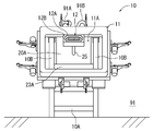
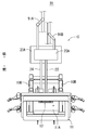
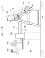
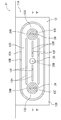
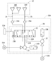
- FIG. 10 It is a front view showing fixture 10 concerning Embodiment 1 of the present invention. It is a top view showing the fixture 10 of FIG. It is a left side view showing mounting tool 10 of Drawing 1A. It is an IV line enlarged arrow view of FIG. FIG. 5 is an end view taken along line V-V of FIG. 4; FIG. 6 is an end elevation similar to FIG. 5 representing a third state of the invention.
- FIG. 10 It is a front view showing the embodiment which remodeled the fixture 10 of FIG.
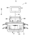
- It is a front view showing the fixture 30 concerning Embodiment 2 of this invention.
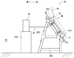
- FIG. 10 is a left side view of the fixture 30 of FIG. 9; It is the XII line enlarged arrow view of FIG.
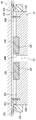
- FIG. 13 is an end view taken along line XIII-XIII of FIG. 12; It is an end elevation similar to FIG.
- this fixture 10 sets a plate-like work (for example, the front door panel 90 of a car) in an inclined state, and performs predetermined processing on this work (for example, a process for folding the edge of the front door panel 90) ) Is possible.
- a plate-like work for example, the front door panel 90 of a car
- predetermined processing on this work for example, a process for folding the edge of the front door panel 90
- the fixture 10 is arrange
- the pressure of the compressed air supplied by the air pressure source 91A is set to be smaller than the pressure of the compressed air supplied by the air pressure source 91B.
- the mounting tool 10 abuts on the front door panel 90 set as a work against the plate surface 90 A along the plate surface 90 A of the front door panel 90, thereby the front door panel 90.
- the support 11 is formed in a rectangular frame shape (see FIGS. 1 and 2) having a through hole 11A at the center, and only a portion of the plate surface 90A of the front door panel 90 which becomes an edge portion of the front door panel 90. It comes in contact with the
- the fixture 10 is rigidly joined to the leg 10A exhibiting a two-layer one-span three-dimensional rigid frame structure and the upper rim of the three-dimensional rigid frame structure of the leg 10A. And two provided in-arms 10B. As shown in FIG. 2 and FIG. 3, these combination palms 10 B are formed by combining two climbing ridges into a mountain shape and rigidly joining them, and the support 11 is attached to one of these climbing ridges in an inclined state Be As a result, as shown in FIG. 3, the support 11 brings the front door panel 90 in contact with the support 11 into an inclined state.
- the legs 10A collectively support the weight of the two doubled palms 10B and the load applied to the doubled palms 10B (for example, the load received from the front door panel 90).
- the side (the right side in FIG. 3) to which the support 11 is attached in the joined palm 10B of the mounting tool 10 is referred to as the “front side” of the mounting tool 10 and the side opposite the front side (the left side in FIG. 3) Will be described as the “rear side” of the fixture 10.
- the fixture 10 is provided with a rectangular parallelepiped casing 20A on the rear side of the leg 10A.
- the housing 20A is placed on a remote control type control unit 23A installed on the floor of the facility 91. Further, air pressure sources 91A and 91B of the facility 91 are connected to the rear side of the housing 20A.
- the control unit 23A controls the operation of the electric actuator 23B by controlling the electric energy supplied to the electric actuator 23B (see FIG. 7) housed in the housing 20A.
- the pad 12 faces the side of the support 11 in contact with the plate surface 90A of the front door panel 90 at the inner edge on the upper side of the rectangular frame. It is attached.
- the pad 12 has a configuration in which an elastomeric lip 12A protrudes annularly from the surface of a metal base 12B.
- the pad 12 can be made to contact
- the pad 12 can be brought into contact with the surface 90A of the front door panel 90.
- the lip portion 12A is inserted into the groove 12D formed in the base portion 12B in the shape of an oval ring (see FIG. 4), and the projecting portion 12J protrudes uniformly from the surface of the base portion 12B.
- the base portion 12B is formed such that an area 12C inside the ring (see FIG. 4) formed by the lip portion 12A in the base portion 12B is planar.
- the pad 12 is provided with a first suction passage 24 and a second suction passage 25 which are separately opened in the area 12C of the base portion 12B.
- the second suction passage 25 has one end opened at the central portion of the oval in the area 12C (see the opening 25B in FIG. 4) and the other end opened in the casing 20A (FIG. 7). Reference).
- the first suction passage 24 is a bifurcated bifurcated pipe (see FIG. 7) bifurcated in the pad 12 and the two ends on the bifurcated side have two openings in the area 12C. It is opened as 24B. As shown in FIGS. 4 and 5, these openings 24B are arranged so as to sandwich the opening 25B of the second suction passage 25 from both sides in the longitudinal direction of the area 12C (both left and right in FIG. 4).
- the end of the first suction passage 24 not open to the area 12C is a filter 24A (see FIG. 7) opened in the housing 20A.
- the pad 12 has a plurality of projections projecting from the area 12C to the side (upper side in FIG. 5) which is the side of the plate surface 90A of the front door panel 90 in the contact state.
- a unit 12H is provided.
- the projecting dimension (see the projecting dimension 12I in FIG. 5) from which the projecting portion 12H projects from the base portion 12B is made to be the same size in any portion of the projecting portion 12H.
- the protrusion dimension 12I of the protrusion 12H with respect to the base 12B is smaller than the protrusion dimension 12J of the lip 12A with respect to the base 12B.
- each of the projecting portions 12H forms a plurality (four in FIG. 4) of convex stripes extending in the longitudinal direction (left and right direction as viewed in FIG. 4) of the oval of the area 12C.
- the protrusion 12H is an elastomeric rectangular string fitted in a groove 12F formed linearly in the area 12C of the base 12B.
- the pad 12 is provided with two packing portions 12G which are protruded from the area 12C to the side of the front door panel 90 which is the side of the plate surface 90A in the contact state.
- the protrusion dimension (see the protrusion dimension 12K in FIG. 5) from which the packing portion 12G protrudes from the base portion 12B is made to be the same size at any portion in the packing portion 12G.
- the protrusion dimension 12I of the protrusion 12H with respect to the base 12B is larger than the protrusion dimension 12J of the lip 12A with respect to the base 12B.
- the packing portion 12G is disposed in such a manner as to surround the periphery of each of the two openings 24B in the area 12C.
- the packing portion 12G is an angular ring made of an elastomer fitted in a groove 12E formed annularly in the area 12C of the base portion 12B.
- the negative pressure unit 20 having the air pressure sources 91A and 91B as a power source is housed in the housing 20A of the fixture 10.
- the negative pressure unit 20 is provided with a rough suction device 21 which is constantly driven by a relatively low pressure air pressure source 91A and sucks air from the suction port 21A.
- the negative pressure unit 20 is provided with a main suction device 22 which is always driven by a relatively high pressure air pressure source 91B and sucks air from the suction port 22A with a suction force stronger than the rough suction device 21.
- the rough suction device 21 is an ejector pump provided with a silencer 21B.
- the main suction device 22 is an ejector pump provided with a silencer 22B.
- the negative pressure unit 20 includes the filter 24A of the first suction passage 24, the filter 25A of the second suction passage 25, the suction port 21A of the rough suction device 21, and the suction port 22A of the true suction device 22.
- a switching system 23 connected to each other.
- the switching system 23 has an electric actuator 23B, and in accordance with the operation of the electric actuator 23B, the connection states of the respective components connected to the switching system 23 will be described below (A) (B) (C) It is supposed to switch to any of the states).
- the electric actuator 23B operates in accordance with the operation of a remote control (not shown) of the control unit 23A. However, the electric actuator 23B can also be set to operate according to a robot program previously input to the control unit 23A.
- the method to perform desired processing to the front door panel 90 is demonstrated using the fixture 10 which has each structure mentioned above.
- the operator operates the remote control (not shown) of the control unit 23A in advance to switch the switching system 23 of the negative pressure unit 20 to the state of (A) described above. Switch on.
- This state is an abutting state in which both the suction of air via the first suction passage 24 and the suction of air via the second suction passage 25 are stopped, and the “first state” in the present invention It corresponds to
- the switching system 23 of the negative pressure unit 20 is switched from the state of (A) described above to the state of (B) described above.
- the negative pressure unit 20 starts suction of air through the first suction path 24 by the rough suction device 21, and the plate surface 90 A of the front door panel 90 and the packing portion 12 G of the pad 12 Negative pressure is applied in the enclosed space 90D (see FIG. 5).
- the packing portion 12G is deformed so as to be crushed by the atmospheric pressure applied to the front door panel 90 from the opposite side to the space 90D which is a negative pressure, as shown by an imaginary line in FIG. Then, the distance 90C between the base 12B of the pad 12 and the plate surface 90A of the front door panel 90 becomes short, and the lip 12A of the pad 12 abuts on the plate surface 90A of the front door panel 90.
- the negative pressure unit 20 brings the plate surface 90A of the front door panel 90 into a suction state where the plate surface 90A is suctioned to the pad 12.
- This state is an adsorption state in which air is sucked through the first suction passage 24 and the flow of air through the second suction passage 25 is stopped, and the “second state” in the present invention It corresponds to In other words, the negative pressure unit 20 switches from the first state to the second state.
- the front door panel 90 In the second state, since the suction force acting on the front door panel 90 is relatively weak, the front door panel 90 is temporarily fixed so as to be able to move in a shear on the support 11 of the fixture 10. Therefore, the operator can easily adjust the position of the front door panel 90 that has been temporarily fixed.
- a distance 90C between the plate surface 90A of the front door panel 90 and the base 12B of the pad 12 is a projection dimension 12I from which the projection 12H is projected from the base 12B (see FIG. 5) It will be longer than).
- the protrusion 12H of the pad 12 is positioned with a gap (see the phantom line in FIG. 6) with the plate surface 90A of the front door panel 90.
- the switching system 23 of the negative pressure unit 20 is switched to the state of (C) described above.
- the negative pressure unit 20 performs suction of air through the first suction passage 24 by the rough suction device 21 to suction of air through the second suction passage 25 by the real suction device 22. Switch. Then, the negative pressure unit 20 reduces the air pressure in the space 90B surrounded by the plate surface 90A of the front door panel 90 and the lip portion 12A of the pad 12 to a pressure lower than the air pressure in the space 90D.
- the negative pressure unit 20 brings the plate surface 90A of the front door panel 90 into a state of being attracted by the pad 12 with a relatively strong force.
- This state is an adsorption state where air is sucked through the second suction path 25 and the flow of air through the first suction path 24 is stopped, and the “third state” in the present invention It corresponds to In other words, the negative pressure unit 20 switches from the second state to the third state.
- the suction force acting on the front door panel 90 causes the front door panel 90 to be held stably with respect to the fixture 10. Then, the operator performs desired processing on the front door panel 90 in the holding state.
- the amount of deformation of the protrusion 12H due to the force received from the plate surface 90A of the front door panel 90 is as small as negligible.
- the protrusion 12H may be deformed (not shown) so as to be crushed by the plate surface 90A of the front door panel 90.
- the distance 90C between the base 12B of the pad 12 and the plate surface 90A of the front door panel 90 is a protrusion 12I (see FIG. 5) from which the protrusion 12H is projected from the base 12B. It becomes below.
- the switching system 23 of the negative pressure unit 20 is switched to the state of (A) described above.
- the filter 24A of the first suction passage 24 and the filter 25A of the second suction passage 25 are opened to the outside air, and the negative pressure in the space 90D and the space 90B disappears.
- the front door panel 90 can be freely removed from the fixture 10. Then, the operator removes the front door panel 90 from the fixture 10 to complete the operation.
- the fixture 10 described above is a switching system of the negative pressure unit 20 as to whether the front door panel 90 is adsorbed by the rough suction device 21 with relatively weak suction force or the main suction device 22 with relatively strong suction force. It can be switched by 23. Thereby, the state in which the front door panel 90 is adsorbed to the fixture 10 by the rough suction device 21 having a relatively weak suction force is maintained for a long time, and the position adjustment of the front door panel 90 is performed while this state is maintained. It becomes easy to do.
- the fixture 10 stops the flow of air through the first suction passage 24.
- air can be sucked from the first suction passage 24 and the suction force of the front door panel 90 can be prevented from being weakened.
- the mounting tool 10 sucks the front door panel 90 by the suction device 22 having a relatively strong suction force, air is sucked from the first suction passage 24 of the packing portion 12G of the pad 12. It can function as a packing to avoid
- the protrusion 12H of the pad 12 can function as a spacer. This prevents the negative pressure from bending the front door panel 90 and the bending of the front door panel 90 from collapsing the space 90 B where suction is performed.
- the mounting tool 10 sucks the front door panel 90 by the rough suction device 21 which has a relatively weak suction force, there is a clearance between the protrusion 12H of the pad 12 and the plate surface 90A of the front door panel 90. Position on Thus, the protrusion 12H of the pad 12 can be prevented from interfering with the suction of air by the rough suction device 21.
- Embodiment 2 which is one of the embodiments for implementing this invention is demonstrated using drawing.
- the fixture 30 is a modification of the fixture 10 according to the first embodiment described above. Therefore, about the composition which is common with each composition of the above-mentioned fitting 10 in fitting 30, the code which added "20" to the code attached to these each composition is made to correspond, and the detailed explanation is omitted. .
- the fixture 30 is, as shown in FIGS. 9 to 11, an oil rotary vacuum having a rotational speed control function instead of the negative pressure unit 20 (see FIG. 7) powered by two pneumatic pressure sources 91A and 91B.
- a negative pressure unit 40 consisting of a pump is provided.
- the negative pressure unit 40 changes the rotational speed of the oil rotary vacuum pump to suck air at a relatively weak negative pressure, suck air at a relatively strong negative pressure, and air It is possible to switch to the stop state where the suction is not performed.
- the negative pressure unit 40 is provided with only one suction passage 45 for suctioning air. That is, in place of the pad 12 (see FIG. 5), which allows both suction of air through the first suction passage 24 and suction of air through the second suction passage 25, the fixture 30 can be used.
- a pad 32 capable of suctioning air via a suction passage 45 is provided.
- the pad 32 does not have a configuration corresponding to the opening 24B and the packing portion 12G (see FIG. 4) provided in the pad 12 as shown in FIGS. 12 to 14.
- the pad 32 is provided so as to border the base portion 32B, and is a skirt portion which is projected to surround the ring formed by the lip portion 32A. 32E is provided.
- the skirt portion 32E is configured to be flexible but not breathable (for example, a closed-cell rubber sponge).
- the skirt portion 32E is provided with an end edge portion 32G which is formed in a strip shape which can be largely reduced against an external force.
- the edge portion 32G is on the side of the plate surface 90A (upper side in FIG. 13) in the contact state (see the imaginary line in FIG. 13) in which the pad 32 is in contact with the plate surface 90A of the front door panel 90. It is protruded in the state where it was inclined toward the outside of.
- the skirt portion 32E has flexibility to allow the end edge portion 32G to move in the direction along the surface of the base portion 32B (in the left and right direction in FIG. 13).
- a projecting dimension 32K in which the end edge portion 32G of the skirt portion 32E is projected from the base portion 32B is larger than a projecting dimension 32J in which the lip portion 32A is projected from the base portion 32B.
- the negative pressure unit 40 is switched from the stop state to a state where suction of air is performed with relatively weak negative pressure, and a space 90D surrounded by the plate surface 90A of the front door panel 90 and the skirt portion 32E of the pad 32 (see FIG. Make negative pressure in the inside).
- the end edge 32G of the skirt portion 32E is deformed so as not to be pushed by the atmospheric pressure applied to the front door panel 90 from the opposite side to the space 90D which is a negative pressure, as shown by an imaginary line in FIG. Do.
- the negative pressure unit 40 brings the plate surface 90A of the front door panel 90 into a suction state where the plate surface 90A is sucked by the pad 32.
- This state corresponds to the "roughing state" in the present invention, and the distance 90C between the base portion 32B and the plate surface 90A of the front door panel 90 in the roughing state is smaller than the above-described projecting dimension 32K.
- the distortion of the edge portion 32G of the skirt portion 32E is negligibly small compared with the proportional limit of the skirt portion 32E.
- the front door panel 90 is temporarily fixed so as to be movable in the direction along the surface of the base portion 32B (horizontal direction in FIG. 13) within the elastic limit of the skirt portion 32E while maintaining the suctioned state. . Therefore, the operator can easily adjust the position of the front door panel 90 in the temporarily fixed state.
- the force applied to the front door panel 90 is a force applied by switching the negative pressure unit 40 to a state where suction of air is performed with a relatively strong negative pressure, even if the operator applies the pressure by pressing the front door panel 90. It may be.
- the operator performs desired processing on the front door panel 90.
- the suction force acting on the front door panel 90 is insufficient to hold the front door panel 90 stably to the fixture 30, the operator strongly strengthens the negative pressure generated by the negative pressure unit 40. Operations can be performed. Therefore, the operator brings the front door panel 90 to the fixture 30 in the main pulling state (see the phantom line in FIG. 14) that achieves the suction state of the front door panel 90 with a relatively strong negative pressure by the negative pressure unit 40.
- a stable holding state can be achieved.
- the operator switches the negative pressure unit 40 to the stop state.
- the suction path 45 is opened to the outside air, and the negative pressure in the space 90D disappears.
- the front door panel 90 can be freely removed from the fixture 30. Then, the operator removes the front door panel 90 from the fixture 30 to complete the operation.
- the negative pressure unit 40 can switch whether the front door panel 90 is attracted by the attachment 30 described above, which is a rough pulling state in which the suction force is relatively weak or a main pulling state in which the suction force is relatively strong. As a result, the state in which the front door panel 90 is adsorbed to the fixture 30 is maintained for a long time due to the rough pulling state where the suction force is relatively weak, and the position adjustment of the front door panel 90 is facilitated while this state is maintained. It will be possible to do.
- the attachment 30 attracts the front door panel 90 in a rough pull state where the suction force is relatively weak
- the front door panel within the elastic limit of the skirt portion 32E while maintaining the adsorbed state. 90 can be moved in the direction along the surface of the base 32B.
- the operator can easily adjust the position of the front door panel 90 that has been temporarily fixed.
- the fixture 10 shown in FIGS. 1 to 3 has its support 11 formed in the shape of a rectangular frame, and has only one pad 12 at the upper inner edge of the rectangular frame.
- the number and arrangement of the pads provided on the fixture can vary.
- a total of four pads 12 are arranged at each edge of the rectangular frame support 11.
- the shape and size of the support provided in the fixture can be changed in accordance with the material, shape, size, etc. of the work set in the fixture.
- the rough suction device and the suction device of the negative pressure unit are not limited to the ejector pump driven by the pneumatic pressure source that supplies compressed air of different pressures. That is, for example, the rough suction device is an oil rotary pump, and the main suction device is a pump assembly incorporating a mechanical booster pump, etc., thereby changing a specific device used as a rough suction device or a main suction device. be able to.
- the number and specific shape of the protrusions provided in the area inside the ring formed by the lip can be changed. Also, one or both of these protrusions or packing may be omitted from the pad of the fixture.
- the fixture 30 shown in FIG. 9 has a skirt 32E whose pad 32 has a non-breathable configuration.
- a configuration in which air leaks out can be employed.
- This configuration may be, for example, a hole or a gap set on the periphery of the skirt bordering the base, or an incomplete seal between the base and the skirt.
- the negative pressure generated by the negative pressure unit is weakened by the leakage of air from the skirt portion and works on the work. The power is reduced.
Landscapes
- Engineering & Computer Science (AREA)
- Mechanical Engineering (AREA)
- Robotics (AREA)
- Manipulator (AREA)
- Jigs For Machine Tools (AREA)
Abstract
La présente invention porte sur un outil de fixation (10) comprenant: un corps de support (11) qui supporte un panneau de porte avant (90) (pièce à travailler) dans un état incliné; un tampon (12) qui peut entrer en contact avec une surface de plaque (90A) du panneau de porte avant (90); et une unité de pression négative (20) qui met l'intérieur d'un espace entouré par la surface de plaque (90A) et le tampon (12) sous pression négative et met la surface de plaque (90A) du panneau de porte avant (90) dans un état aspiré. L'unité de pression négative (20) peut être commutée entre un état d'arrêt dans lequel l'état aspiré n'est pas atteint, un état de pompage grossier dans lequel l'état aspiré est atteint tandis que la pression négative est relativement affaiblie, et un état de pompage principal dans lequel l'état aspiré est atteint tandis que la pression négative est relativement renforcée.
Priority Applications (4)
| Application Number | Priority Date | Filing Date | Title |
|---|---|---|---|
| CN201880056520.0A CN111050991A (zh) | 2017-09-07 | 2018-08-08 | 固定装置 |
| JP2018560682A JP6692928B2 (ja) | 2017-09-07 | 2018-08-08 | 取付具 |
| US16/644,030 US20200346312A1 (en) | 2017-09-07 | 2018-08-08 | Fixture |
| EP18854556.0A EP3680061A4 (fr) | 2017-09-07 | 2018-08-08 | Outil de fixation |
Applications Claiming Priority (2)
| Application Number | Priority Date | Filing Date | Title |
|---|---|---|---|
| JP2017-172116 | 2017-09-07 | ||
| JP2017172116 | 2017-09-07 |
Publications (1)
| Publication Number | Publication Date |
|---|---|
| WO2019049596A1 true WO2019049596A1 (fr) | 2019-03-14 |
Family
ID=65634005
Family Applications (1)
| Application Number | Title | Priority Date | Filing Date |
|---|---|---|---|
| PCT/JP2018/029819 Ceased WO2019049596A1 (fr) | 2017-09-07 | 2018-08-08 | Outil de fixation |
Country Status (5)
| Country | Link |
|---|---|
| US (1) | US20200346312A1 (fr) |
| EP (1) | EP3680061A4 (fr) |
| JP (1) | JP6692928B2 (fr) |
| CN (1) | CN111050991A (fr) |
| WO (1) | WO2019049596A1 (fr) |
Cited By (2)
| Publication number | Priority date | Publication date | Assignee | Title |
|---|---|---|---|---|
| IT202000017167A1 (it) * | 2020-07-15 | 2022-01-15 | Prussiani Eng S P A | Dispositivo di posizionamento e bloccaggio per materiale in lastra o parte di essa |
| JP2025080256A (ja) * | 2023-11-14 | 2025-05-26 | トライエンジニアリング株式会社 | 吸引パッド、加工装置および加工方法 |
Families Citing this family (3)
| Publication number | Priority date | Publication date | Assignee | Title |
|---|---|---|---|---|
| CN112296700B (zh) * | 2020-10-30 | 2021-09-21 | 永固集团股份有限公司 | 用于断路器零部件加工的吸附结构 |
| CN113070740B (zh) * | 2021-04-07 | 2023-05-30 | 昆明弘固机械制造有限公司 | 一种薄壁氧化铝陶瓷结构件的高效加工方法及负压夹具 |
| CN114887795B (zh) * | 2022-05-05 | 2025-12-05 | 兰州交通大学 | 一种基于高熵合金表面涂层用固定装置 |
Citations (5)
| Publication number | Priority date | Publication date | Assignee | Title |
|---|---|---|---|---|
| JPS62100835U (fr) * | 1985-12-16 | 1987-06-26 | ||
| JPS6364442U (fr) * | 1986-10-18 | 1988-04-28 | ||
| JP2004179472A (ja) | 2002-11-28 | 2004-06-24 | Noritake Co Ltd | ワーク固定装置 |
| WO2009081621A1 (fr) * | 2007-12-21 | 2009-07-02 | Mitsuboshi Diamond Industrial Co., Ltd. | Appareil et procédé de traitement laser |
| JP2010142891A (ja) * | 2008-12-17 | 2010-07-01 | Linkstar Japan Co Ltd | 基板テーブルおよびそれを用いたレーザ加工装置 |
Family Cites Families (23)
| Publication number | Priority date | Publication date | Assignee | Title |
|---|---|---|---|---|
| JPS524979U (fr) * | 1975-06-24 | 1977-01-13 | ||
| US4527783A (en) * | 1983-04-26 | 1985-07-09 | Grumman Aerospace Corporation | Universal contoured parts holding fixture |
| JPH0638447B2 (ja) * | 1987-05-29 | 1994-05-18 | テラダイン株式会社 | ウエハ位置決め方法 |
| JPH01104796U (fr) * | 1987-12-30 | 1989-07-14 | ||
| JP2763261B2 (ja) * | 1993-12-21 | 1998-06-11 | セントラル硝子株式会社 | 吸着パッド |
| JPH081604A (ja) * | 1994-06-21 | 1996-01-09 | Marunaka Kakoki Kk | 木製パネル用吸着装置 |
| JPH0866841A (ja) * | 1994-08-25 | 1996-03-12 | Canon Inc | 物品の保持方法及びその装置 |
| JPH08197470A (ja) * | 1995-01-18 | 1996-08-06 | Toyota Auto Body Co Ltd | 真空吸着カップ |
| JPH10128633A (ja) * | 1996-10-28 | 1998-05-19 | Nippon Telegr & Teleph Corp <Ntt> | 真空吸着装置 |
| JPH10249770A (ja) * | 1997-03-12 | 1998-09-22 | Aida Eng Ltd | バキュームカップ |
| JPH11130278A (ja) * | 1997-10-31 | 1999-05-18 | Kawasaki Steel Corp | 真空吸着パッドおよび真空吸着装置 |
| JP2004034195A (ja) * | 2002-07-01 | 2004-02-05 | Central Glass Co Ltd | 吸着パッド |
| DE602004025084D1 (de) * | 2003-01-29 | 2010-03-04 | Mitsuboshi Diamond Ind Co Ltd | Vakuum saugkopf |
| JP3769618B2 (ja) * | 2003-04-21 | 2006-04-26 | 防衛庁技術研究本部長 | 真空吸着装置 |
| JP2006224199A (ja) * | 2005-02-15 | 2006-08-31 | Nissan Motor Co Ltd | 吸着装置 |
| JP2007253249A (ja) * | 2006-03-20 | 2007-10-04 | Honda Motor Co Ltd | 吸着装置及びこの吸着装置を用いた吸着方法 |
| US8079578B2 (en) * | 2007-09-05 | 2011-12-20 | Hgs Aerospace, Inc. | Universal holding fixture |
| JP5436999B2 (ja) * | 2009-09-24 | 2014-03-05 | 株式会社ディスコ | 被加工物保持装置 |
| KR101126685B1 (ko) * | 2010-03-03 | 2012-03-29 | 한동희 | 필름 부착장치 및 부착방법 |
| DE102011107381A1 (de) * | 2011-06-29 | 2013-01-03 | Brötje-Automation GmbH | Handhabungswerkzeug |
| JP6140966B2 (ja) * | 2011-10-14 | 2017-06-07 | キヤノン株式会社 | インプリント装置、それを用いた物品の製造方法 |
| JP2014200888A (ja) * | 2013-04-05 | 2014-10-27 | ローム株式会社 | 吸引保持装置およびウエハ研磨装置 |
| JP6340277B2 (ja) * | 2014-07-18 | 2018-06-06 | 株式会社ディスコ | 加工装置 |
-
2018
- 2018-08-08 US US16/644,030 patent/US20200346312A1/en not_active Abandoned
- 2018-08-08 WO PCT/JP2018/029819 patent/WO2019049596A1/fr not_active Ceased
- 2018-08-08 EP EP18854556.0A patent/EP3680061A4/fr not_active Withdrawn
- 2018-08-08 JP JP2018560682A patent/JP6692928B2/ja not_active Expired - Fee Related
- 2018-08-08 CN CN201880056520.0A patent/CN111050991A/zh active Pending
Patent Citations (5)
| Publication number | Priority date | Publication date | Assignee | Title |
|---|---|---|---|---|
| JPS62100835U (fr) * | 1985-12-16 | 1987-06-26 | ||
| JPS6364442U (fr) * | 1986-10-18 | 1988-04-28 | ||
| JP2004179472A (ja) | 2002-11-28 | 2004-06-24 | Noritake Co Ltd | ワーク固定装置 |
| WO2009081621A1 (fr) * | 2007-12-21 | 2009-07-02 | Mitsuboshi Diamond Industrial Co., Ltd. | Appareil et procédé de traitement laser |
| JP2010142891A (ja) * | 2008-12-17 | 2010-07-01 | Linkstar Japan Co Ltd | 基板テーブルおよびそれを用いたレーザ加工装置 |
Non-Patent Citations (1)
| Title |
|---|
| See also references of EP3680061A4 * |
Cited By (3)
| Publication number | Priority date | Publication date | Assignee | Title |
|---|---|---|---|---|
| IT202000017167A1 (it) * | 2020-07-15 | 2022-01-15 | Prussiani Eng S P A | Dispositivo di posizionamento e bloccaggio per materiale in lastra o parte di essa |
| JP2025080256A (ja) * | 2023-11-14 | 2025-05-26 | トライエンジニアリング株式会社 | 吸引パッド、加工装置および加工方法 |
| JP7781443B2 (ja) | 2023-11-14 | 2025-12-08 | トライエンジニアリング株式会社 | 吸引パッド、加工装置および加工方法 |
Also Published As
| Publication number | Publication date |
|---|---|
| JP6692928B2 (ja) | 2020-05-13 |
| CN111050991A (zh) | 2020-04-21 |
| JPWO2019049596A1 (ja) | 2019-11-07 |
| EP3680061A4 (fr) | 2021-06-09 |
| EP3680061A1 (fr) | 2020-07-15 |
| US20200346312A1 (en) | 2020-11-05 |
Similar Documents
| Publication | Publication Date | Title |
|---|---|---|
| WO2019049596A1 (fr) | Outil de fixation | |
| JP6592567B2 (ja) | 剥離装置 | |
| JP6663354B2 (ja) | 吸引装置および吸引ロボット | |
| TWI733020B (zh) | 工作夾台 | |
| TW201447256A (zh) | 氣密測試設備及氣密測試方法 | |
| CN107073659A (zh) | O型环安装装置及方法 | |
| JP2019502563A (ja) | 吸着装置 | |
| JP2017213663A (ja) | 吸着装置、飛行ロボット | |
| CN108582957A (zh) | 贴合装置及贴合方法 | |
| JP2005288595A (ja) | 吸着パッド装置 | |
| CN108025587B (zh) | 粘贴装置和粘贴方法 | |
| WO2022024897A1 (fr) | Gabarit de maintien de pièces, système de robot et procédé de montage de pièces | |
| CN204369096U (zh) | 吸盘装置 | |
| JP5506511B2 (ja) | フィルム貼り合わせ装置 | |
| JP2017127929A (ja) | 吸着器 | |
| JPH1126553A (ja) | 吸着コレット | |
| JP2002144270A (ja) | 吸着ジグ及び被搬送物の搬送方法 | |
| CN118156204A (zh) | 晶圆搬运设备及其吸盘模块 | |
| JP2004076916A (ja) | 差動排気シール装置 | |
| WO2025142720A1 (fr) | Gabarit de fixation par aspiration, dispositif de fixation par aspiration et dispositif de transport | |
| CN113280203A (zh) | 一种正负压便捷式切换方法 | |
| CN206561234U (zh) | 固定用治具及超声波点焊固定机构 | |
| CN215172250U (zh) | 气阀组件、气流驱动组件及输送系统 | |
| JPS6320553Y2 (fr) | ||
| CN211277548U (zh) | Cnc方格超强力磁盘 |
Legal Events
| Date | Code | Title | Description |
|---|---|---|---|
| ENP | Entry into the national phase |
Ref document number: 2018560682 Country of ref document: JP Kind code of ref document: A |
|
| 121 | Ep: the epo has been informed by wipo that ep was designated in this application |
Ref document number: 18854556 Country of ref document: EP Kind code of ref document: A1 |
|
| NENP | Non-entry into the national phase |
Ref country code: DE |
|
| ENP | Entry into the national phase |
Ref document number: 2018854556 Country of ref document: EP Effective date: 20200407 |