WO2019093143A1 - Capteur d'élément - Google Patents
Capteur d'élément Download PDFInfo
- Publication number
- WO2019093143A1 WO2019093143A1 PCT/JP2018/039656 JP2018039656W WO2019093143A1 WO 2019093143 A1 WO2019093143 A1 WO 2019093143A1 JP 2018039656 W JP2018039656 W JP 2018039656W WO 2019093143 A1 WO2019093143 A1 WO 2019093143A1
- Authority
- WO
- WIPO (PCT)
- Prior art keywords
- substrate
- tube
- convex portion
- component sensor
- end side
- Prior art date
- Legal status (The legal status is an assumption and is not a legal conclusion. Google has not performed a legal analysis and makes no representation as to the accuracy of the status listed.)
- Ceased
Links
Images

Classifications
-
- G—PHYSICS
- G01—MEASURING; TESTING
- G01N—INVESTIGATING OR ANALYSING MATERIALS BY DETERMINING THEIR CHEMICAL OR PHYSICAL PROPERTIES
- G01N21/00—Investigating or analysing materials by the use of optical means, i.e. using sub-millimetre waves, infrared, visible or ultraviolet light
- G01N21/17—Systems in which incident light is modified in accordance with the properties of the material investigated
- G01N21/55—Specular reflectivity
- G01N21/552—Attenuated total reflection
-
- G—PHYSICS
- G01—MEASURING; TESTING
- G01N—INVESTIGATING OR ANALYSING MATERIALS BY DETERMINING THEIR CHEMICAL OR PHYSICAL PROPERTIES
- G01N21/00—Investigating or analysing materials by the use of optical means, i.e. using sub-millimetre waves, infrared, visible or ultraviolet light
- G01N21/84—Systems specially adapted for particular applications
- G01N21/85—Investigating moving fluids or granular solids
-
- G—PHYSICS
- G01—MEASURING; TESTING
- G01J—MEASUREMENT OF INTENSITY, VELOCITY, SPECTRAL CONTENT, POLARISATION, PHASE OR PULSE CHARACTERISTICS OF INFRARED, VISIBLE OR ULTRAVIOLET LIGHT; COLORIMETRY; RADIATION PYROMETRY
- G01J3/00—Spectrometry; Spectrophotometry; Monochromators; Measuring colours
- G01J3/28—Investigating the spectrum
- G01J3/42—Absorption spectrometry; Double beam spectrometry; Flicker spectrometry; Reflection spectrometry
-
- G—PHYSICS
- G01—MEASURING; TESTING
- G01J—MEASUREMENT OF INTENSITY, VELOCITY, SPECTRAL CONTENT, POLARISATION, PHASE OR PULSE CHARACTERISTICS OF INFRARED, VISIBLE OR ULTRAVIOLET LIGHT; COLORIMETRY; RADIATION PYROMETRY
- G01J5/00—Radiation pyrometry, e.g. infrared or optical thermometry
- G01J5/02—Constructional details
- G01J5/08—Optical arrangements
-
- G—PHYSICS
- G01—MEASURING; TESTING
- G01J—MEASUREMENT OF INTENSITY, VELOCITY, SPECTRAL CONTENT, POLARISATION, PHASE OR PULSE CHARACTERISTICS OF INFRARED, VISIBLE OR ULTRAVIOLET LIGHT; COLORIMETRY; RADIATION PYROMETRY
- G01J5/00—Radiation pyrometry, e.g. infrared or optical thermometry
- G01J5/58—Radiation pyrometry, e.g. infrared or optical thermometry using absorption; using extinction effect
-
- G—PHYSICS
- G01—MEASURING; TESTING
- G01N—INVESTIGATING OR ANALYSING MATERIALS BY DETERMINING THEIR CHEMICAL OR PHYSICAL PROPERTIES
- G01N21/00—Investigating or analysing materials by the use of optical means, i.e. using sub-millimetre waves, infrared, visible or ultraviolet light
- G01N21/01—Arrangements or apparatus for facilitating the optical investigation
- G01N21/03—Cuvette constructions
-
- G—PHYSICS
- G01—MEASURING; TESTING
- G01N—INVESTIGATING OR ANALYSING MATERIALS BY DETERMINING THEIR CHEMICAL OR PHYSICAL PROPERTIES
- G01N21/00—Investigating or analysing materials by the use of optical means, i.e. using sub-millimetre waves, infrared, visible or ultraviolet light
- G01N21/17—Systems in which incident light is modified in accordance with the properties of the material investigated
- G01N21/25—Colour; Spectral properties, i.e. comparison of effect of material on the light at two or more different wavelengths or wavelength bands
- G01N21/27—Colour; Spectral properties, i.e. comparison of effect of material on the light at two or more different wavelengths or wavelength bands using photo-electric detection ; circuits for computing concentration
-
- G—PHYSICS
- G01—MEASURING; TESTING
- G01N—INVESTIGATING OR ANALYSING MATERIALS BY DETERMINING THEIR CHEMICAL OR PHYSICAL PROPERTIES
- G01N21/00—Investigating or analysing materials by the use of optical means, i.e. using sub-millimetre waves, infrared, visible or ultraviolet light
- G01N21/17—Systems in which incident light is modified in accordance with the properties of the material investigated
- G01N21/25—Colour; Spectral properties, i.e. comparison of effect of material on the light at two or more different wavelengths or wavelength bands
- G01N21/31—Investigating relative effect of material at wavelengths characteristic of specific elements or molecules, e.g. atomic absorption spectrometry
- G01N21/35—Investigating relative effect of material at wavelengths characteristic of specific elements or molecules, e.g. atomic absorption spectrometry using infrared light
- G01N21/3577—Investigating relative effect of material at wavelengths characteristic of specific elements or molecules, e.g. atomic absorption spectrometry using infrared light for analysing liquids, e.g. polluted water
Definitions
- the present disclosure relates to a device such as a fluid component detection device that detects the concentration of a fluid component by using absorption characteristics of light such as infrared light.
- Patent Document 1 A component sensor using an ATR method using a prism is known (Patent Document 1).
- a component sensor using an infrared ray transmitting fiber in a sample container is known as a method of improving the performance of a component sensor that measures a component of a fluid using an ATR (Attenuated Total Reflection) method (Patented Patent Documents 2 and 3).
- this indication aims to solve the above-mentioned problem and to provide a ingredient sensor which improved detection accuracy of a detection subject.
- the component sensor of the present disclosure has the following configuration. That is, a tube portion having a tube side to which a fluid can flow, a substrate provided on the tube portion, a first convex portion provided on one end side of the substrate, and a first portion provided on the other end side of the substrate And a light emitting portion that emits infrared light toward the first convex portion, and a light receiving portion that receives infrared light.
- the infrared light incident on the substrate from the first convex portion is totally reflected in the substrate and emitted from the second convex portion toward the light receiving portion.
- the tube side surface is provided with two through holes penetrating the inside and outside of the tube portion. The substrate is inserted from the through hole, and the central portion of the substrate is disposed inside the tube.
- One end side of the substrate provided with the first convex portion and the other end side of the substrate provided with the second convex portion are disposed outside the tube portion.
- the present disclosure improves the sensitivity of the component sensor by allowing the substrate to pass through the tube, and improves the detection accuracy of the component of the detection target because deformation of the substrate through which infrared rays pass is small. be able to.
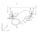
- a perspective view of a component sensor according to an embodiment of the present disclosure II-II cross section of the same component sensor The perspective view of the modification of the same ingredient sensor
- FIG. 1 is a perspective view of the component sensor according to the embodiment
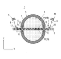
- FIG. 2 is a cross-sectional view of the component sensor taken along line II-II.
- the infrared ray trajectory is indicated by a straight line.
- FIG. 2 shows the fluid to be detected.
- the component sensor 1 includes a tube portion 3 to which the fluid 2 to be detected can flow, a substrate 5 which penetrates the tube side surface 4 of the tube portion 3 and both ends are outside the tube portion 3, and a substrate A light emitting portion for emitting an infrared ray 8 toward the first convex portion 6 provided on one end side of the second convex portion 7 provided on the other end side of the substrate 5 and the first convex portion 6
- a light receiving unit 10 is provided to receive the infrared rays 8 emitted from the second protrusion 7 and the second protrusion 7.
- the substrate 5 is sealed in the tube portion 3 by the sealing member 11.
- fuel of a car can be considered.
- the fuel is composed of a hydrocarbon-forming component, ethanol, water and the like.
- the hydrocarbon-forming component is, for example, an aromatic type, an olefin type, or a paraffin type.
- the extending direction of the tube portion 3 is orthogonal to the X-axis direction, the direction connecting the both ends of the substrate 5 extending from the tube portion 3 to the Y-axis direction, both the X-axis direction and the Y-axis direction Will be described as the Z-axis direction.
- the tube portion 3 is formed in a cylindrical shape and extends in the X-axis direction. Since the fluid 2 flows inside the tube portion 3, in the description of the component sensor 1, the direction in which the fluid 2 flows inside the tube portion 3 is described as the direction in which the tube portion 3 extends.
- the tube portion 3 is not limited to a cylindrical shape, and may be a curved shape, but in the embodiment, the tube portion 3 will be described using the cylindrical shape tube portion 3 shown in FIG.
- the shape of the cross section of the tube portion 3 in the YZ plane direction is not limited to a circular shape, and may be another shape such as an elliptical shape, a rectangular shape, or a polygonal shape. Openings 12 are provided at both ends of the tube portion 3 in the X-axis direction.
- the fluid 2 to be detected flows in or out from the opening 12.
- the tube portion 3 has a tube side 4 sandwiched by two openings 12.
- Two through holes 13 for inserting the substrate 5 are provided in the tube side surface 4, and the substrate 5 is inserted into the through holes 13.
- the central portion of the substrate 5 in the Y-axis direction is disposed inside the tube portion 3.
- One end side of the substrate 5 on which the first convex portion 6 is provided and the other end side of the substrate 5 on which the second convex portion 7 is provided are disposed outside the pipe portion 3. ing.
- the substrate 5 is formed of silicon, and the first major surface 14 and the second major surface 15 on the back surface of the first major surface 14, and the substrate side surface between the first major surface 14 and the second major surface 15. There are sixteen.
- the material of the substrate 5 is not limited to silicon, but can be easily processed by forming it with silicon.
- a first convex portion 6 and a second convex portion 7 are provided in a region of the substrate 5 disposed outside the tube portion 3.
- the first convex portion 6 and the second convex portion 7 are positioned on the first main surface 14 of the substrate 5 on the opposite side of the pipe portion 3 with the first convex portion 6 and the second convex portion 7 interposed therebetween. It is provided to do.
- the first convex portion 6, the pipe portion 3, and the second convex portion 7 are arranged in order in the Y-axis direction.
- the first convex portion 6 and the second convex portion 7 are provided on the first major surface 14 of the substrate 5, the present invention is not limited to this.
- the first convex portion 6 may be a first major surface 14 and the second protrusion 7 may be provided on the second major surface 15.
- the first convex portion 6 and the second convex portion 7 are prisms, and since the first convex portion 6 and the second convex portion 7 are provided integrally with the substrate 5, the first convex portion 6 and the second convex portion 7 are integrated.
- the two convex portions 7 can be easily formed.
- the first convex portion 6 is provided with a first inclined surface 17.
- Infrared rays 8 enter the substrate 5 from the first inclined surface 17 of the first convex portion 6.
- the refractive index of the substrate 5 is larger than the refractive index of the fluid 2.
- the infrared rays 8 incident from the first convex portion 6 into the substrate 5 are the first interface 18 between the first major surface 14 of the substrate 5 and the fluid 2, the second major surface 15, and the fluid 2
- the total reflection is repeated at the second interface 19 and advances toward the second convex portion 7.
- the infrared rays 8 reaching the second convex portion 7 are emitted from the second inclined surface 20 of the second convex portion 7 to the outside of the substrate 5.
- the first inclined surface 17 and the second inclined surface 20 are formed by anisotropic etching.
- the first and second inclined surfaces 17 and 20 can be easily formed by anisotropic etching.
- the plane orientation of the first inclined surface 17 and the second inclined surface 20 is (111), and the angle ⁇ with respect to the second major surface 15 is 54.7 °.
- the infrared rays 8 form the first interface 18 between the substrate 5 and the fluid 2 and Total reflection occurs at the second interface 19.
- the angle ⁇ of the first inclined surface 17 and the second inclined surface 20 with respect to the second major surface 15 may be other than 54.7 °, but the angle of 54.7 ° corresponds to the first inclined surface 17
- the second inclined surface 20 can be easily processed.
- the substrate 5 penetrates the tube portion 3, the evanescent wave penetrates into the fluid 2 outside the substrate 5 when the infrared rays 8 are totally reflected at the first interface 18 and the second interface 19, and the fluid 2 Absorbed and attenuated.
- the component of the fluid 2 can be detected by detecting this amount of attenuation.
- silicon is used as the substrate 5, and the substrate 5 is less likely to be deformed even under the pressure of the fluid 2. Therefore, the substrate 5 is more than the conventional component sensor as shown in Patent Documents 2 and 3 The decrease in the detection accuracy of the component sensor 1 due to the deformation of is small.
- Length L1 in a direction connecting the two substrate side surfaces 16 of the first main surface 14 and the second main surface 15 Is longer than a length L2 in the direction connecting the first major surface 14 and the second major surface 15 of the substrate side 16 (hereinafter referred to as the width of the substrate side 16).
- the width L1 of the first major surface 14 and the width L1 of the second major surface 15 are described as being equal for convenience of description, the present invention is not limited to this.
- the first major surface 14 and the second major surface 15 are provided so as to be parallel to the extending direction (X-axis direction) of the pipe portion 3.
- the first main surface 14 and the second main surface 15 are parallel to the X-axis direction
- the pressure that the substrate 5 receives from the fluid 2 can be reduced.
- deformation of the substrate 5 due to the pressure received from the fluid 2 can be reduced, so that the decrease in detection accuracy of the component sensor 1 can be suppressed.
- substrate 5 in FIG. 3 is shown. As shown in FIG.
- the substrate 5 is disposed in a direction in which the first major surface 14 is orthogonal to the X-axis direction (the direction in which the first major surface 14 and the second major surface 15 are parallel to the YZ plane)
- the pressure received from the fluid 2 can be reduced by arranging the first major surface 14 so as not to be orthogonal to the X-axis direction.
- the same effect can be obtained by arranging the substrate 5 in the direction in which the pressure received from the fluid 2 is minimized.
- the substrate 5 is sealed using a sealing member 11 in a sealing region R in which the through holes 13 are provided.
- a metal packing covered with a reflection film such as gold or silver that easily reflects the infrared rays 8 is used.
- the amount of attenuation when the infrared rays 8 are reflected by the sealing region sealed by the sealing member 11 is reduced.
- the infrared rays 8 are reflected by the sealing area, the infrared rays 8 are absorbed by the sealing member 11 so that the infrared rays 8 are attenuated and the sensitivity of the component sensor 1 is lowered.
- the sealing member 11 is covered with gold or silver as in the component sensor 1, the absorption of the infrared rays 8 by the sealing member 11 can be suppressed, so that the sensitivity of the component sensor 1 can be improved.
- the positional relationship between the light emitting portion 9 and the first convex portion 6 may be adjusted, and the angle of the infrared ray 8 may be adjusted so that the infrared ray does not reflect in the sealing region R. Since the infrared rays 8 are not absorbed by the sealing member 11 by making the infrared rays 8 incident at such an angle, the sensitivity of the component sensor 1 can be improved.
- the light emitting unit 9 uses a platinum thin film resistive element capable of emitting the infrared light 8.
- a light emitting diode capable of emitting infrared rays 8 may be used.
- a semiconductor bare chip may be used as the light emitting diode.
- the light emitting unit 9 is provided on the side of the first main surface 14 of the substrate 5, and is disposed such that the infrared light 8 is incident on the first convex portion 6.
- the light emitting unit 9 emits infrared light 8 having a wavelength that is easily absorbed by the fluid 2 to be detected.
- infrared rays 8 having a wavelength of 2 ⁇ m or more and 15 ⁇ m or less are used.
- the concentration of the fluid 2 to be detected can be detected accurately.
- the wavelength range can be narrowed with an optical band pass filter (not shown) or the like that matches the absorption wavelength specific to the two components of the fluid to be measured.
- the light emission part 9 may have two or more light sources from which a wavelength differs.
- a semiconductor bare chip is used for the light receiving unit 10.
- an element other than a semiconductor bare chip such as a pyroelectric element or a photodiode may be used.
- the light receiving unit 10 is disposed at a position where the infrared light 8 emitted from the second convex portion 7 on the side where the substrate 5 of the tube portion 3 is provided can be detected.
- the light receiving unit 10 has two light receiving elements (not shown) and two optical filters (not shown) provided at positions corresponding to the two light receiving elements, respectively. The two optical filters transmit infrared rays 8 of different wavelengths.
- One of the optical filters transmits infrared rays 8 of a wavelength at which the absorption amount of the fluid 2 is large, and the other optical filter transmits infrared rays 8 of a wavelength at which the absorption amount of the fluid 2 is small.
- the component sensor 1 uses two light receiving elements and two optical filters in order to detect the components of the fluid 2 with high accuracy, but the components of the fluid 2 can be detected even if one light receiving element and one optical filter are used. I can do it.
- three or more light receiving elements and three or more optical filters may be provided. The types of detectable components can be increased by increasing the number of light receiving elements and optical filters.
- the light emitting unit 9 and the light receiving unit 10 are housed in a housing and attached to the pipe unit 3, and the infrared rays 8 are incident from the first convex portion 6 into the substrate 5 to form a second convex. It is fixed so as to emit from the portion 7 toward the light receiving portion 10.
- the component sensor of the present disclosure can detect the component of the fluid with high accuracy, and thus is suitable for detection of the concentration of the fuel component of a vehicle.
Landscapes
- Physics & Mathematics (AREA)
- General Physics & Mathematics (AREA)
- Spectroscopy & Molecular Physics (AREA)
- Health & Medical Sciences (AREA)
- Life Sciences & Earth Sciences (AREA)
- Chemical & Material Sciences (AREA)
- Analytical Chemistry (AREA)
- Biochemistry (AREA)
- General Health & Medical Sciences (AREA)
- Immunology (AREA)
- Pathology (AREA)
- Engineering & Computer Science (AREA)
- Mathematical Physics (AREA)
- Theoretical Computer Science (AREA)
- Investigating Or Analysing Materials By Optical Means (AREA)
- Optical Measuring Cells (AREA)
Abstract
La présente invention améliore la précision de détection d'élément fluide d'un capteur d'élément. Ce capteur d'élément comprend : une section de tube (3) ayant une surface latérale de tube (4), à partir de laquelle un fluide (2) peut circuler ; un substrat (5) qui est disposé dans la section de tube (3) ; une première section en saillie (6) qui est disposée sur une extrémité du substrat (5) ; une seconde section en saillie (7) qui est disposée sur l'autre extrémité du substrat (5) ; une section d'émission de lumière (9) qui émet une lumière infrarouge (8) vers la première section en saillie (6) ; et une section de réception de lumière (10) qui reçoit la lumière infrarouge (8). La lumière infrarouge (8) appliquée sur le substrat (5) à partir de la première section en saillie (6) est totalement réfléchie dans le substrat (5), et est émise vers la section de réception de lumière à partir de la seconde section en saillie (7). La surface latérale de tube (4) est pourvue de deux trous traversants (13) qui pénètrent dans la section de tube (3) de l'intérieur vers l'extérieur de la section de tube. Le substrat (5) est inséré à partir des trous traversants (13), et une partie centrale du substrat (5) est disposée à l'intérieur de la section de tube (3). Une extrémité du substrat (5), ladite extrémité étant pourvue de la première section en saillie (6), et l'autre extrémité du substrat (5), ladite autre extrémité étant pourvue de la seconde section en saillie (7), sont disposées à l'extérieur de la section de tube (3).
Priority Applications (1)
| Application Number | Priority Date | Filing Date | Title |
|---|---|---|---|
| US16/639,148 US11320372B2 (en) | 2017-11-07 | 2018-10-25 | Component sensor |
Applications Claiming Priority (2)
| Application Number | Priority Date | Filing Date | Title |
|---|---|---|---|
| JP2017214414A JP6850969B2 (ja) | 2017-11-07 | 2017-11-07 | 成分センサ |
| JP2017-214414 | 2017-11-07 |
Publications (1)
| Publication Number | Publication Date |
|---|---|
| WO2019093143A1 true WO2019093143A1 (fr) | 2019-05-16 |
Family
ID=66437900
Family Applications (1)
| Application Number | Title | Priority Date | Filing Date |
|---|---|---|---|
| PCT/JP2018/039656 Ceased WO2019093143A1 (fr) | 2017-11-07 | 2018-10-25 | Capteur d'élément |
Country Status (3)
| Country | Link |
|---|---|
| US (1) | US11320372B2 (fr) |
| JP (1) | JP6850969B2 (fr) |
| WO (1) | WO2019093143A1 (fr) |
Citations (8)
| Publication number | Priority date | Publication date | Assignee | Title |
|---|---|---|---|---|
| JPS57111435A (en) * | 1980-12-27 | 1982-07-10 | Horiba Ltd | Measuring device for absorption intensity of infrared ray by atr method |
| JPS57111423A (en) * | 1980-12-27 | 1982-07-10 | Horiba Ltd | Measuring device for absorption intensity of infrared ray by atr method |
| JPS61178622A (ja) * | 1985-02-04 | 1986-08-11 | Tokyo Gas Co Ltd | 気体の分光装置 |
| JPS63154941A (ja) * | 1986-12-19 | 1988-06-28 | Ricoh Co Ltd | 流体の物性値測定装置 |
| JPH02162244A (ja) * | 1988-12-16 | 1990-06-21 | Hisankabutsu Glass Kenkyu Kaihatsu Kk | ファイバーを用いた赤外分光分析方法 |
| JPH08313430A (ja) * | 1995-05-18 | 1996-11-29 | Nippon Telegr & Teleph Corp <Ntt> | ガスセンサ |
| US6016372A (en) * | 1997-10-16 | 2000-01-18 | World Precision Instruments, Inc. | Chemical sensing techniques employing liquid-core optical fibers |
| US6819811B1 (en) * | 2000-11-09 | 2004-11-16 | Quantum Group Inc. | Nano-size gas sensor systems |
Family Cites Families (8)
| Publication number | Priority date | Publication date | Assignee | Title |
|---|---|---|---|---|
| JPH0720046A (ja) | 1993-07-06 | 1995-01-24 | Canon Inc | 液体クロマトグラフ用赤外分光セル |
| US6096564A (en) * | 1999-05-25 | 2000-08-01 | Wisconsin Alumni Research Foundation | Plasma-aided treatment of surfaces against bacterial attachment and biofilm deposition |
| JP2002286636A (ja) * | 2001-01-19 | 2002-10-03 | Advantest Corp | 化学物質検出方法及び装置 |
| US7255835B2 (en) * | 2001-09-04 | 2007-08-14 | North Carolina State University | Single pass attenuated total reflection fourier transform infrared microscopy apparatus and method for identifying protein secondary structure, surface charge and binding affinity |
| EP1478913B1 (fr) * | 2002-02-25 | 2016-12-07 | Waters Technologies Corporation | Cuve ou tube de guidage de lumière en fluoropolymère amorphe avec un dopant noir |
| US20050141843A1 (en) * | 2003-12-31 | 2005-06-30 | Invitrogen Corporation | Waveguide comprising scattered light detectable particles |
| CN100462711C (zh) * | 2005-06-10 | 2009-02-18 | 鸿富锦精密工业(深圳)有限公司 | 纳米材料相转移侦测装置及方法 |
| US9897541B1 (en) * | 2017-01-20 | 2018-02-20 | The United States Of America, As Represented By The Secretary Of Commerce | Attenuated total reflection flow cell |
-
2017
- 2017-11-07 JP JP2017214414A patent/JP6850969B2/ja not_active Expired - Fee Related
-
2018
- 2018-10-25 WO PCT/JP2018/039656 patent/WO2019093143A1/fr not_active Ceased
- 2018-10-25 US US16/639,148 patent/US11320372B2/en active Active
Patent Citations (8)
| Publication number | Priority date | Publication date | Assignee | Title |
|---|---|---|---|---|
| JPS57111435A (en) * | 1980-12-27 | 1982-07-10 | Horiba Ltd | Measuring device for absorption intensity of infrared ray by atr method |
| JPS57111423A (en) * | 1980-12-27 | 1982-07-10 | Horiba Ltd | Measuring device for absorption intensity of infrared ray by atr method |
| JPS61178622A (ja) * | 1985-02-04 | 1986-08-11 | Tokyo Gas Co Ltd | 気体の分光装置 |
| JPS63154941A (ja) * | 1986-12-19 | 1988-06-28 | Ricoh Co Ltd | 流体の物性値測定装置 |
| JPH02162244A (ja) * | 1988-12-16 | 1990-06-21 | Hisankabutsu Glass Kenkyu Kaihatsu Kk | ファイバーを用いた赤外分光分析方法 |
| JPH08313430A (ja) * | 1995-05-18 | 1996-11-29 | Nippon Telegr & Teleph Corp <Ntt> | ガスセンサ |
| US6016372A (en) * | 1997-10-16 | 2000-01-18 | World Precision Instruments, Inc. | Chemical sensing techniques employing liquid-core optical fibers |
| US6819811B1 (en) * | 2000-11-09 | 2004-11-16 | Quantum Group Inc. | Nano-size gas sensor systems |
Also Published As
| Publication number | Publication date |
|---|---|
| JP6850969B2 (ja) | 2021-03-31 |
| US11320372B2 (en) | 2022-05-03 |
| JP2019086382A (ja) | 2019-06-06 |
| US20200232917A1 (en) | 2020-07-23 |
Similar Documents
| Publication | Publication Date | Title |
|---|---|---|
| CN102869980B (zh) | 具有辐射导管的气体传感器 | |
| KR102246478B1 (ko) | 농도 측정 장치 | |
| TW201840999A (zh) | 垂直腔表面發射雷射低發散角近接感測器 | |
| CN107532995B (zh) | 光学分析装置及其制造方法 | |
| CN110383043A (zh) | 光学气体传感器 | |
| KR101067348B1 (ko) | 편광각 투과 유도 프리즘 및 이를 이용한 신호 대 잡음비 향상을 위한 형광검출장치 | |
| KR102522728B1 (ko) | 침착물 센서를 구비한 광 센서 | |
| CN110779892B (zh) | 液滴传感器 | |
| JP6850969B2 (ja) | 成分センサ | |
| US9188528B2 (en) | Sensor for monitoring a medium | |
| US10025077B2 (en) | Device for measuring solution concentration | |
| KR102223821B1 (ko) | 다종 가스 측정 장치 | |
| JP5199083B2 (ja) | 流路センサ及びそれに用いるチューブ固定具 | |
| TWI915692B (zh) | 濃度測定裝置 | |
| CN115552205A (zh) | 用于检测气体和悬浮物的光学检测器 | |
| JP2023109050A (ja) | 光学式物理量測定装置 | |
| JP2015102455A (ja) | センサ装置および測定方法 | |
| JP2004177242A (ja) | 筒内物理量検出装置 | |
| JP2024124340A (ja) | 光学式物理量測定装置 | |
| KR102265564B1 (ko) | 산란광 측정 방식의 가스 센싱 시스템 | |
| WO2018105455A1 (fr) | Capteur de composant | |
| WO2024116593A1 (fr) | Dispositif de mesure de concentration | |
| JP2018013349A (ja) | 流路セルと、この流路セルを備えたセンサ | |
| CN206594056U (zh) | 水分测定装置 | |
| WO2016121338A1 (fr) | Capteur |
Legal Events
| Date | Code | Title | Description |
|---|---|---|---|
| 121 | Ep: the epo has been informed by wipo that ep was designated in this application |
Ref document number: 18876018 Country of ref document: EP Kind code of ref document: A1 |
|
| NENP | Non-entry into the national phase |
Ref country code: DE |
|
| 122 | Ep: pct application non-entry in european phase |
Ref document number: 18876018 Country of ref document: EP Kind code of ref document: A1 |