WO2019123990A1 - 二軸配向熱可塑性樹脂フィルム - Google Patents
二軸配向熱可塑性樹脂フィルム Download PDFInfo
- Publication number
- WO2019123990A1 WO2019123990A1 PCT/JP2018/043483 JP2018043483W WO2019123990A1 WO 2019123990 A1 WO2019123990 A1 WO 2019123990A1 JP 2018043483 W JP2018043483 W JP 2018043483W WO 2019123990 A1 WO2019123990 A1 WO 2019123990A1
- Authority
- WO
- WIPO (PCT)
- Prior art keywords
- film
- less
- thermoplastic resin
- biaxially oriented
- height
- Prior art date
- Legal status (The legal status is an assumption and is not a legal conclusion. Google has not performed a legal analysis and makes no representation as to the accuracy of the status listed.)
- Ceased
Links
Images


Classifications
-
- B—PERFORMING OPERATIONS; TRANSPORTING
- B32—LAYERED PRODUCTS
- B32B—LAYERED PRODUCTS, i.e. PRODUCTS BUILT-UP OF STRATA OF FLAT OR NON-FLAT, e.g. CELLULAR OR HONEYCOMB, FORM
- B32B3/00—Layered products comprising a layer with external or internal discontinuities or unevennesses, or a layer of non-planar shape; Layered products comprising a layer having particular features of form
- B32B3/26—Layered products comprising a layer with external or internal discontinuities or unevennesses, or a layer of non-planar shape; Layered products comprising a layer having particular features of form characterised by a particular shape of the outline of the cross-section of a continuous layer; characterised by a layer with cavities or internal voids ; characterised by an apertured layer
- B32B3/30—Layered products comprising a layer with external or internal discontinuities or unevennesses, or a layer of non-planar shape; Layered products comprising a layer having particular features of form characterised by a particular shape of the outline of the cross-section of a continuous layer; characterised by a layer with cavities or internal voids ; characterised by an apertured layer characterised by a layer formed with recesses or projections, e.g. hollows, grooves, protuberances, ribs
-
- C—CHEMISTRY; METALLURGY
- C08—ORGANIC MACROMOLECULAR COMPOUNDS; THEIR PREPARATION OR CHEMICAL WORKING-UP; COMPOSITIONS BASED THEREON
- C08J—WORKING-UP; GENERAL PROCESSES OF COMPOUNDING; AFTER-TREATMENT NOT COVERED BY SUBCLASSES C08B, C08C, C08F, C08G or C08H
- C08J5/00—Manufacture of articles or shaped materials containing macromolecular substances
- C08J5/18—Manufacture of films or sheets
-
- B—PERFORMING OPERATIONS; TRANSPORTING
- B29—WORKING OF PLASTICS; WORKING OF SUBSTANCES IN A PLASTIC STATE IN GENERAL
- B29C—SHAPING OR JOINING OF PLASTICS; SHAPING OF MATERIAL IN A PLASTIC STATE, NOT OTHERWISE PROVIDED FOR; AFTER-TREATMENT OF THE SHAPED PRODUCTS, e.g. REPAIRING
- B29C55/00—Shaping by stretching, e.g. drawing through a die; Apparatus therefor
- B29C55/02—Shaping by stretching, e.g. drawing through a die; Apparatus therefor of plates or sheets
- B29C55/10—Shaping by stretching, e.g. drawing through a die; Apparatus therefor of plates or sheets multiaxial
- B29C55/12—Shaping by stretching, e.g. drawing through a die; Apparatus therefor of plates or sheets multiaxial biaxial
Definitions
- the present invention relates to a biaxially oriented thermoplastic resin film having fine projections on the surface.
- Thermoplastic resins are used in various industrial fields because of their good processability.
- products obtained by processing these thermoplastic resins into a film form play an important role in today's life such as industrial applications, optical products applications, packaging applications, magnetic recording tape applications and the like.
- processability of films used in the manufacture of electronic information devices there is a demand for improvement in processability of films used in the manufacture of electronic information devices.
- many methods are adopted in which other materials are laminated on the film surface and optical processing such as a photoresist is performed on the film. For this reason, in order to improve the processability of a film, it is a general means to improve the smoothness of the film while maintaining the transparency of the film.
- Patent Document 1 a technique for improving the slipperiness by roughening the surface with an additive without containing particles in the film
- Patent Document 2 encloses organic resin particles on the film surface.
- a technique for improving the slipperiness by constructing a coat layer that exhibits slipperiness is disclosed.
- An object of the present invention is to provide a biaxially oriented thermoplastic resin film having good smoothness and slipperiness, and further having improved scratch resistance in film forming and processing steps.
- the present invention takes the following composition. That is, [I] The surface of at least one side has a maximum protrusion height of less than 20 nm, the number of protrusions having a height of 1 nm or more and less than 2 nm is A (pieces / mm 2 ), and the number of protrusions having a height of 3 nm or more and less than 20 nm is B The biaxially-oriented thermoplastic resin film whose B / A is 0.001 or more and 5.000 or less when (in / mm 2 ).
- thermoplastic resin constituting the biaxially oriented thermoplastic resin film is any one of polyester resin, polyethylene resin, polypropylene resin, polyphenylene sulfide resin, and polyimide resin as a main component [I] to [VII]
- the biaxially oriented thermoplastic resin film of the present invention has good transparency, smoothness and slipperiness, and further has scratch resistance in the film forming and processing steps.
- R top R 1 nm as measured by AFM (Atomic Force Microscope)
- R 2nm R 3nm
- the two-layer configuration diagram of the biaxially oriented thermoplastic resin film of the present invention Three-layer configuration diagram of the biaxially oriented thermoplastic resin film of the present invention
- Three-layer structure diagram of the biaxially oriented thermoplastic resin film of the present invention It is a conceptual diagram showing the cross section of the permite
- the present invention relates to biaxially oriented thermoplastic resin films.
- the thermoplastic resin as referred to in the present invention is a resin which exhibits plasticity when heated.
- Representative resins include polyethylene terephthalate, polyethylene naphthalate, polybutylene terephthalate, polyethylene ⁇ , ⁇ -dicarboxylate, polymer from P-hexahydroxylylene terephthalate, polymer from 1,4 cyclohexane dimethanol, poly-P -Polyester resins having an ester bond in the main chain as typified by ethylene oxybenzoate, polyarylate, polycarbonate and the like and copolymers thereof, further nylon 6, nylon 66, nylon 610, nylon 12, nylon 11, etc.
- Polyamide resins having an adduct bond in the main chain as typified by: polyethylene, polypropylene, ethylene vinyl acetate copolymer, polymethylpentene, polybutene, polyisobutylene, polystyrene etc.
- Typical examples are polyolefin resins consisting mainly of hydrocarbon, such as polyether sulfone (PES), polyphenylene oxide (PPO), polyetheretherketone (PEEK), polyethylene oxide, polypropylene oxide, polyoxymethylene, etc.
- Polyether resins polyvinyl chloride, halogenated polymer resins represented by polyvinylidene chloride, polyvinylidene fluoride, polychlorotrifluoroethylene, etc., and polyphenylene sulfide (PPS) resin, polysulfone resin and copolymers thereof And modified products, polyimide resins and the like.
- PPS polyphenylene sulfide
- the thermoplastic resin used in the present invention is preferably composed mainly of polyester resin, polyolefin resin, polyphenylene sulfide (PPS) resin and polyimide (PI) resin from the viewpoint of transparency and film forming property, and among them, especially, among them, especially Polyester is further preferred.
- the term "main component” as used herein refers to a component containing more than 50% by weight and 100% by weight or less in 100% by weight of all components of the film.
- the polyester resin said by this invention is formed by polycondensing a dicarboxylic acid structural component and a diol structural component.
- a component shows the thing of the minimum unit which can be obtained by hydrolyzing a polyester resin.
- dicarboxylic acid component constituting such polyester resin examples include terephthalic acid, isophthalic acid, phthalic acid, 1,4-naphthalenedicarboxylic acid, 1,5-naphthalenedicarboxylic acid, 2,6-naphthalenedicarboxylic acid, 1,8- Aromatic dicarboxylic acids such as naphthalene dicarboxylic acid, 4,4'-diphenyl dicarboxylic acid, 4,4'-diphenyl ether dicarboxylic acid, or ester derivatives thereof can be mentioned.
- diol component which comprises this polyester resin
- ethylene glycol 1, 2- propanediol, 1, 3- propanediol, 1, 4- butanediol, 1, 2- butanediol, 1, 3- butane diol
- Aliphatic diols such as diols, cycloaliphatic diols such as cyclohexanedimethanol, spiroglycol, and the like, and those in which a plurality of the above-mentioned diols are linked are exemplified.
- biomass include sugar resources such as sugar cane and sugar beet, and starch resources such as corn, rice and potato.
- polyester resins polyethylene terephthalate (PET), polyethylene-2,6-naphthalenedicarboxylate (PEN), and some dicarboxylic acid components of PET are isophthalic acid and naphthalene from the viewpoint of mechanical properties and transparency.
- PET polyethylene terephthalate
- PEN polyethylene-2,6-naphthalenedicarboxylate
- the biaxially oriented thermoplastic resin film of the present invention needs to be biaxially oriented.
- the mechanical strength of the film can be improved and the slipperiness can be improved.
- the term "biaxial orientation" as used herein refers to those exhibiting a biaxial orientation pattern by wide-angle X-ray diffraction.
- a biaxially oriented thermoplastic resin film can be obtained by stretching a thermoplastic resin sheet in an unstretched state in the sheet longitudinal direction and the width direction, and then performing heat treatment to complete crystal orientation. Details will be described later.
- the maximum height (maximum protrusion height) of the protrusions measured by AFM (Atomic Force Microscope) according to the method described later is at least one surface of the thermoplastic resin film and R top (nm)
- the number of protrusions having R top (nm) of less than 20 nm and having a height of 1 nm or more and less than 2 nm is A (pieces / mm 2 )
- the number of protrusions having a height of 3 nm or more and less than 20 nm is B (pieces / mm)
- B / A needs to be 0.001 or more and 5.000 or less (hereinafter, the maximum projection height is less than 20 nm, and B / A is 0.001 or more and 5.000 or less
- a film surface may be simply referred to as the surface).
- R top (nm) in the present invention reflects the height of the projection having the largest projection height present on the film surface.
- R top (nm) is 20 nm or more
- the film when the film is wound in a roll, defects occur on the other side of the film, or when laminating another layer on the surface of the film, the projection is formed on another layer Give a defect.
- the processability of the film may be reduced, or the haze of the film may be increased to lose transparency of the film, which may cause defects in optical processing of a photoresist or the like.
- R top when R top is small, the film has no protrusion having a certain protrusion height or more, and the slipperiness of the film may be deteriorated.
- R top (nm) is preferably 3 nm or more and less than 20 nm, more preferably 3 nm or more and 15 nm or less, still more preferably 3 nm or more and 10 nm or less, and most preferably 3 nm or more and 5 nm or less.
- the number A (pieces / mm 2 ) of protrusions having a height of 1 nm or more and less than 2 nm in the present invention reflects the number of protrusions present in the film ground portion of the surface.
- the area when contacting with another surface hereinafter, the area when contacting with another surface may be referred to as a contact area
- the slipperiness of the film is improved.
- the slipperiness of the film may be high, and thus the winding shift may occur at the time of film winding.
- the number A (pieces / mm 2 ) of projections having a height of 1 nm or more and less than 2 nm is preferably 1.0 ⁇ 10 7 pieces / mm 2 or more and 1.0 ⁇ 10 9 pieces / mm 2 or less, more preferably 2 It is not less than 0 ⁇ 10 7 pieces / mm 2 and not less than 5.0 ⁇ 10 8 pieces / mm 2 .
- the number B (pieces / mm 2 ) of protrusions having a height of 3 nm or more and less than 20 nm in the present invention reflects the number of protrusions present at positions away from the ground portion of the surface, and the height present on the ground portion It has the effect of preventing the contact of projections of 1 nm or more and less than 2 nm with other surfaces and further improving the slipperiness of the film. Is a value calculated using the height 1nm or more number of 2nm below projections A number of (pieces / mm 2) and a height of less than 3nm than 20nm protrusion B (number / mm 2) B / A is, both It reflects the balance of the number of projections.
- B / A In the case where B / A is large, the percentage of projections having a height of 1 nm or more and less than 2 nm contributing to the slipperiness is reduced, so that the slipperiness is reduced, and the film formation / processing suitability of the film is reduced. In addition, when B / A is small, the ratio of projections having a height of 3 nm or more and less than 20 nm is decreased, and the area in which the other surface contacts the film base portion is increased. ⁇ The processing accuracy decreases. In addition to this, many scratches occur due to the friction between the film and the process roll. A more preferable range of B / A is 0.010 or more and 2.000 or less, and a further preferable range is 0.010 or more and 0.080 or less.
- the number of less than height 3 nm 20 nm protrusions B (number / mm 2) and the height 1nm or more number of 2nm below the projections A (number / mm 2), the number A is when trying to increase the number B
- the B / A can be controlled to the above-mentioned range by the method described later in the present invention.
- the number C (pieces / mm 2 ) of protrusions having a height of 2 nm or more and less than 3 nm in the present invention is the number A (pieces / mm 2 ) of protrusions having a height of 1 nm or more and less than 2 nm and the height 3 nm to less than 20 nm
- the number of projections present at an intermediate position of the number of projections B (pieces / mm 2 ) is reflected.
- the number of projections C (number / mm 2 ) is not particularly limited, but when R top (nm) which is the maximum projection height is 5 nm or less, the influence can not be neglected, and the projections having a height of 1 nm or more and less than 2 nm. It has been found that the scratch resistance may change depending on the value of C / A, which is a ratio to the number A (pieces / mm 2 ) of. Specifically, it is preferable that the value of C / A is 0.100 or more and 2.000 or less when R top (nm) is 5 nm or less. More preferably, it is 0.200 or more and 0.400 or less.
- the value of C / A is less than 0.100, even if the value of C / A is within the preferable range, the influence of the other surface coming into contact with the ground surface can not be ignored, and the scratch resistance may decrease.
- the value of C / A is greater than 2.000, the base portion is no different from being present at a protrusion having a height of 2 nm or more and less than 3 nm, and the scratch resistance of the film may be reduced.
- the number of protrusions having a height of 1 nm or more and less than 10 nm on the surface of the biaxially oriented thermoplastic resin film of the present invention is D (pieces / mm 2 )
- the number D is the height of protrusions from the vicinity of the ground existing on the surface It represents the total number of protrusions present at a high position less than 10 nm, and the total number of protrusions that play a role in preventing adhesion (blocking) between the films and the associated wrinkles when the film is wound on a roll.
- the roll may be tightened depending on the storage temperature when the roll is stored for a long time.
- the film in a roll state receives a large pressure in the thickness direction.
- the inventors of the present invention have intensively studied, among the protrusions present on the surface, the protrusions having a protrusion height of 10 nm or more contribute to pressure dispersion, while the height of the protrusions becomes high and the difference in height from the ground portion causes wrinkles. It has been found that it may contribute to the occurrence of surface defects.
- the number of protrusions D with a protrusion height of 1 nm or more and less than 10 nm is 5.0 ⁇ 10 7 to 6.0 ⁇ 10 9 pieces / mm 2 It is preferable that When the number of protrusions D is less than 5.0 ⁇ 10 7 pieces / mm 2 , the contact area between the films in the roll state is increased to cause adhesion, making it difficult to unroll the film, or During storage in the condition, wrinkles and surface defects may occur frequently.
- the number of protrusions D exceeds 6.0 ⁇ 10 9 pieces / mm 2 , blocking of the films can be suppressed, but there may be a case where the film is misaligned to lower productivity.
- the preferable range of the number of protrusions D is 1.7 ⁇ 10 8 to 1.0 ⁇ 10 9 pieces / mm 2 , and more preferably 2.0 ⁇ 10 8 to 8.0 ⁇ 10 8 pieces / mm 2 . is there.
- the surface of the biaxially oriented thermoplastic resin film of the present invention preferably has an arithmetic average roughness Ra of 3.0 nm or less, more preferably 0.5 nm or more and 3.0 nm or less. . If it is less than 0.5 nm, there are few projections effective to reduce the contact area, and slipperiness (slidability) may be reduced. On the other hand, when it exceeds 3.0 nm, since there are coarse projections, when the biaxially oriented thermoplastic resin film of the present invention is wound, unevenness may be transferred and the smoothness of the film may be lost.
- the surface of the biaxially oriented thermoplastic resin film of the present invention is determined by AFM measurement described later, and the average value D1 nm of the circle equivalent diameter of the cross section of the protrusion at a position 1 nm high from the reference surface is 15 nm or more and 30 nm or less Is preferred.
- the average equivalent circle diameter is less than 15 nm, even if the above-mentioned projections are present in large numbers (in high density), they are easily deformed at the time of contact with other surfaces, and serve to reduce the contact area It may not be.
- the average value of the equivalent circle diameter exceeds 30 nm, the projections are coarse, the number of projections having a height of 1 nm or more and less than 2 nm may be reduced, and as a result, the slipperiness of the film may be reduced.
- the atmospheric pressure is in the range of 700 Torr to 780 Torr.
- a film to be treated is introduced between the opposite electrode and the earth roll, a plasma exciting gas is introduced into the apparatus, and the gas is plasma excited by applying a high frequency voltage between the electrodes.
- a glow discharge is performed between the electrodes. Thereby, the film surface is finely processed to form projections.
- the plasma-exciting gas refers to a gas that can be plasma-excited under the conditions as described above.
- plasma-exciting gases include rare gases such as argon, helium, neon, krypton and xenon, nitrogen, carbon dioxide, oxygen, fluorocarbons such as tetrafluoromethane, and mixtures thereof.
- the plasma-exciting gas may be used alone or in combination of two or more at an arbitrary mixing ratio. From the viewpoint of increasing the activity when excited by plasma, it is preferable to contain at least one of argon, oxygen and carbon dioxide, and it is more preferable to contain oxygen.
- the frequency of the high frequency voltage in plasma processing is preferably in the range of 1 kHz to 100 kHz.
- the discharge treatment strength (E value) determined by the following method is preferably in the range of 10 to 2000 W ⁇ min / m 2 from the viewpoint of protrusion formation, more preferably 40 to 500 W ⁇ min / m 2 is there. If the discharge treatment strength (E value) is too low, projections may not be formed sufficiently, and if the discharge treatment strength (E value) is too high, the thermoplastic resin film may be damaged or ashing proceeds And preferred projections may not be formed.
- E Vp ⁇ Ip / (S ⁇ Wt)
- E E value (W ⁇ min / m 2 )
- Vp Applied voltage
- Ip Applied current
- S Processing speed (m / min)
- Wt Processing width (m)
- FIG. 1 A conceptual diagram showing R top , R 1 nm , R 2 nm, R 3 nm and R 20 nm measured by AFM is shown in FIG.
- the reference surface is a height determined such that the distance from the reference surface on the measurement surface is 0 (a positive value if higher than the reference surface, a negative value if lower than the reference surface). Value).
- thermoplastic resin film particularly a film having an amorphous part and a crystalline part such as PET or PEN
- it is processed from a soft amorphous part.
- finely dividing the crystal part and the amorphous part finer protrusions can be formed by atmospheric pressure glow discharge treatment, and the soft amorphous part is deeply scraped by increasing the crystal part. Can increase the height of the protrusions.
- the intrinsic viscosity (IV) of the layer having the surface of the thermoplastic resin film of the present invention is preferably 0.55 dl / g or more, more preferably 0.70 dl / g or more.
- IV is a number reflecting the length of the molecular chain, and the longer the molecular chain, the crystallographic part and the amorphous part are easily formed clearly in the same molecular chain, so by atmospheric pressure glow discharge treatment It is preferable because formation of finer projections is facilitated.
- IV is less than 0.55 dl / g, crystallization is likely to progress due to the short molecular chain, so breakage may frequently occur in the stretching step, making film formation difficult.
- R top (nm) tends to be increased by dispersing other thermoplastic resin components in the nano-order size in the thermoplastic resin constituting the film. Further, it is also effective means to increase the strength of the atmospheric pressure glow discharge treatment and the activity of the plasma exciting gas used in the atmospheric pressure glow discharge treatment.
- the biaxially oriented thermoplastic resin film of the present invention may have a single-layer structure or a structure of two or more layers in which other resins are laminated.
- P1 layer When the layer having the surface is referred to as P1 layer and the layer to be laminated is referred to as P2 layer, P1 layer / P2 layer configuration in which the surface having the protrusion of P1 layer is the outermost layer Is preferred.
- P1 layer / P2 layer / P1 layer In the case of a three-layer structure, it may be a two-kind three-layer structure (P1 layer / P2 layer / P1 layer) or a different three-layer structure (P1 layer / P2 layer / P3 layer) in which another resin is laminated. .
- the method for laminating other resin layers such as P1 layer and P2 layer or P3 layer is not particularly limited, but coextrusion method to be described later, or another resin layer raw material is added to the film in the middle of film formation
- a method of melt extruding and laminating while extruding from a die (melt laminating method), a method of laminating films after film formation with an adhesive layer, and the like can be used, among them.
- a coextrusion process which can be performed is preferably used.
- the coefficient of friction ( ⁇ k) between the metal and the surface having the projections under the measurement conditions described later is preferably 0.20 or more and 0.55 or less. More preferably, it is 0.20 or more and 0.40 or less, and most preferably 0.20 or more and 0.37 or less. If it exceeds 0.55, the slipperiness is not sufficient and the film of the present invention can not be formed and processed. When it is less than 0.20, winding deviation may occur when winding the film of the present invention.
- the haze of the film is preferably 0.60% or less.
- the haze of the film exceeds 0.60%, transmitted light is scattered when the film is used, and for example, in dry film resist support applications, defects occur in the resist wiring. More preferably, it is 0.50% or less, still more preferably 0.45% or less.
- the biaxially oriented thermoplastic resin film of the present invention may contain organic particles and / or inorganic particles as long as the properties of the present invention are not impaired, but in order to obtain the maximum properties of the present invention Is preferably substantially free of particles.
- the phrase "containing substantially no particles” means that the content of particles with respect to the thermoplastic resin film is 500 ppm or less, more preferably 50 ppm or less, and most preferably 10 ppm or less.
- the biaxially oriented thermoplastic resin film of the present invention adds an AS agent (antistatic agent) for the purpose of preventing electrification or imparts optical characteristics according to the intended use within the range that does not impair the characteristics of the present invention.
- AS agent antistatic agent
- Dyes, dyes, and organic and inorganic wavelength conversion materials may be added for the purpose.
- thermoplastic resin film of the present invention will be described by taking a biaxially oriented polyester resin film as an example, but the present invention is interpreted as being limited to only those obtained by this example. It is not a thing.
- a polymerization method by a conventional method can be adopted.
- melt polymerization It can be obtained by conducting a reaction.
- the solid phase polymerization reaction may be performed on the polyester resin obtained by the melt polymerization reaction below the melting point temperature of the polyester resin.
- the biaxially oriented thermoplastic resin film of the present invention can be obtained by the conventionally known production method, but by producing the stretching and heat treatment steps under the following conditions, the formation of projections is controlled and it has the preferable physical properties as described above. It can be a surface.
- the biaxially oriented thermoplastic resin film of the present invention uses a method (melt casting method) in which the dried raw material is heated and melted in an extruder if necessary, and extruded from a die onto a cast drum cooled can do.
- a method melting method
- the raw material is dissolved in a solvent, and the solution is extruded from a die onto a support such as a cast drum or an endless belt to form a film, and then the solvent is removed by drying from the film layer to form a sheet.
- a method (solution casting method) or the like can also be used.
- an extruder is used for each layer constituting the laminated polyester film to melt the raw materials of each layer, and these are provided between the extruder and the die.
- a method (co-extrusion method) of laminating in a molten state with a joining device, guiding to a die, and extruding from a die onto a cast drum to process into a sheet shape is suitably used.
- the laminated sheet is solidified by contact cooling and solidified by static electricity on a drum cooled to a surface temperature of 20 ° C. or more and 60 ° C. or less to produce an unstretched film.
- the temperature of the casting drum is more preferably 25 ° C. or more and 60 ° C.
- atmospheric pressure glow discharge treatment described later may be applied to form projections on the film surface after biaxial stretching. If the temperature exceeds 60 ° C., the film may stick to the cast drum, making it difficult to obtain an unstretched film.
- the unstretched film obtained here is subjected to surface treatment such as plasma treatment by atmospheric pressure glow discharge.
- surface treatment such as plasma treatment by atmospheric pressure glow discharge.
- These surface treatments may be performed immediately after obtaining the unstretched film, after being slightly stretched, or after stretching in the longitudinal and / or transverse directions, but in the present invention, it is preferable to surface treat the unstretched films.
- the surface to be surface-treated may be either the surface (drum surface) in contact with the cast drum or the surface (non-drum surface) not in contact with the cast drum.
- the unstretched film is biaxially stretched and biaxially oriented.
- a stretching method sequential biaxial stretching method or simultaneous biaxial stretching method can be used.
- a sequential biaxial stretching method in which stretching is performed first in the longitudinal direction and then in the width direction is effective for obtaining the biaxially oriented thermoplastic resin film of the present invention without stretching breakage.
- the stretching conditions in the case of biaxial stretching an unstretched film are not particularly limited, but when the biaxially oriented thermoplastic resin film of the present invention is mainly made of a polyester resin, as stretching in the longitudinal direction, It is preferable that the unstretched film be introduced into a group of rolls heated to 70 ° C. or higher, stretched in the longitudinal direction (longitudinal direction, ie, the sheet traveling direction), and cooled by a group of rolls at a temperature of 20 to 50 ° C.
- the lower limit of the heating roll temperature in stretching in the longitudinal direction is not particularly limited as long as the stretchability of the sheet is not impaired, but the glass transition temperature + 5 ° C of the polyester resin to be used is preferable.
- the preferable range of the stretching ratio in the longitudinal direction is 2.5 times to 5 times.
- a more preferable range is 3.0 times to 3.5 times.
- the draw ratio in the longitudinal direction is 2.5 times or less, the orientation crystallization does not proceed and the film strength is significantly reduced.
- the draw ratio is more than 4.5 times, the orientation crystallization of the polyester resin accompanying the drawing proceeds to make the film brittle and may cause breakage during film formation.
- the film is guided to a tenter while gripping both ends of the film with clips, and is orthogonal to the longitudinal direction in an atmosphere heated to a temperature of 70 to 160 ° C.
- the tenter device set temperature may generally be set so that the maximum temperature in the tenter is 200 ° C. or more and 250 ° C.
- thermoplastic resin when another thermoplastic resin is used as the main component, it is preferable to set the melting point of the thermoplastic resin to ⁇ 55 ° C. or less and the melting point to ⁇ 5 ° C. or less.
- the heat treatment temperature is less than 200 ° C.
- the other thermoplastic resin when the other thermoplastic resin is the main component, the melting point of the thermoplastic resin is less than -55 ° C.
- the protrusions formed by the atmospheric pressure glow discharge treatment may not grow sufficiently, and as a result, it may be difficult to form the protrusions in the above-mentioned preferable range.
- thermoplastic resin when polyethylene terephthalate is the main component and heat treatment is carried out over 250 ° C., in the case where another thermoplastic resin is the main component, heat treatment is carried out over the melting point -5 ° C. of the thermoplastic resin. In some cases, the film melts and breaks frequently, resulting in a decrease in productivity.
- a more preferable range of the heat treatment temperature when polyethylene terephthalate is the main component is 220 ° C. or more and 245 ° C. or less.
- Tmeta which represents the heat history temperature which the film received at the time of heat treatment, when it is mainly composed of polyethylene terephthalate, it is preferable to be 190 ° C. or more and 245 ° C. or less from the above-mentioned reason.
- a more preferable range is 210 ° C. or more and 240 ° C. or less.
- a relaxation (relaxation) treatment may be performed in the range of 0% or more and 6% or less for the purpose of imparting dimensional stability to the film.
- the stretching ratio is 3 to 5 times in the longitudinal direction and the width direction, but the area ratio (longitudinal stretching ratio x transverse stretching ratio) is preferably 9 to 20 times, more preferably 9 to 15 times. preferable.
- the area magnification is less than 9 times, the durability of the obtained biaxially stretched film is insufficient, and when the area magnification is more than 20 times, the film tends to be easily broken during drawing.
- the longitudinal force applied during stretching in this tenter is generally one of the factors that generate bowing, and the Poisson deformation of the film (stretching force in the longitudinal direction) in the stretching zone in the tenter, and the stretching zone And the difference in film stiffness at each temperature as it travels to the higher temperature heat treatment zone.
- the greater the longitudinal force the more the film is drawn toward the longitudinal stretching zone.
- the stress at the time of stretching can be made uniform, and a projection in the above range can be formed.
- the film is highly oriented in the width direction by increasing the mechanical draw ratio in the width direction more than the mechanical draw ratio in the longitudinal direction.
- the mechanical draw ratio in the longitudinal direction is X (%) and the mechanical magnification in the width direction is Y (%)
- the value calculated by Y / X is 1.00 or more More preferably, it is 1.05 or more, more preferably 1.10 or more, and most preferably 1.20 or more.
- the value of Y / X is less than 1.00, the effect of reducing the stress in the longitudinal direction can not be obtained, and the projection may not be controlled to a preferable range.
- Step-up temperature of temperature in tenter Stretching by gradually raising the temperature in the tenter from 80 ° C and raising the maximum temperature of the stretching zone, lowering the maximum temperature of the heat treatment zone, lowering the starting temperature without changing the maximum temperature of the heat treatment zone, etc. This can be achieved by reducing the temperature difference between the zone and the heat treatment zone.
- the temperature difference between the stretching zone and the heat treatment zone is preferably 160 ° C. or less. More preferably, it is 100 ° C. or less, and most preferably 40 ° C. or less.
- the stretching temperature of the film is low, uniform stretching in the width direction can not be performed, and when the occurrence of thickness unevenness and flatness deteriorate, or the temperature of the heat treatment zone is high and the film melts and breaks However, there are cases where productivity may decline.
- Additional stretching in heat treatment zone This can be achieved by stretching in the width direction again in the heat treatment zone disposed behind the stretching zone in the tenter.
- stretching is preferably performed at a mechanical draw ratio of 1.05 times to 1.50 times in the width direction.
- the draw ratio in the width direction is smaller than 1.05, the effect of suppressing the longitudinal force may not be obtained.
- the draw ratio in the width direction is larger than 1.50 times, the film becomes brittle due to the increase in the degree of crystallization, and the uniformity of drawing may be broken or breakage may occur frequently, which may lower productivity. is there.
- the film of the present invention obtained as described above has good smoothness and slipperiness, and is also excellent in scratch resistance in film forming and processing steps. Taking advantage of the characteristics, for example, it is suitably used as a release film (in particular, a release film of a polarizing plate or a release film used for producing a laminated ceramic capacitor) or a support of a magnetic recording medium.
- the polarizing plate is a cross nicol method (two polarizing plates have their polarization planes orthogonal to each other as foreign material contamination or defect inspection, and the film is sandwiched between the polarization planes of the polarizing plate whose longitudinal direction and width direction are orthogonal to each other). Visual inspection of human beings)).
- thermoplastic resin film of the present invention can suppress the occurrence of such problems while having excellent releasability, and thus can be suitably used as a release film of a polarizing plate.
- thermoplastic resin film of the present invention has good smoothness and slipperiness, and is also excellent in scratch resistance in film forming and processing steps, so it should be suitably used as a release film used for producing a laminated ceramic capacitor. Can.
- thermoplastic resin film when used as a support of a magnetic recording medium, it has the following problems.
- magnetic recording media have been required to achieve higher density recording.
- it is effective to make the magnetic layer thin and use fine particle magnetic materials to further improve the smoothness of the surface of the magnetic layer.
- the thickness of the magnetic layer, the nonmagnetic layer, the backcoat layer, and further the support itself is reduced. Not only the smooth surface but also the roughening of the running surface is restricted.
- the projections formed on the running surface are transferred to the magnetic surface, and a depression is formed on the smooth magnetic layer surface to deteriorate the smoothness of the magnetic layer surface.
- the characteristics deteriorate. Only by reducing the diameter and reducing the concentration of the particles contained on the running surface side of the support in order to enhance the smoothness of the magnetic layer surface, the phenomenon that the added particles overlap in the thickness direction and the particles are pushed up to the surface As it happens, the coarse projections can not be improved yet.
- the smoothness of the film is enhanced, the slipperiness between the film and the process roll tends to decrease, and therefore, the transportability of the film in the processing step decreases.
- thermoplastic resin film of the present invention can suppress the occurrence of such problems while having excellent releasability, and therefore, as a support of a magnetic recording medium, particularly as a support of a coating type digital recording system It can be used suitably.
- the threshold height (Threshold Height) of the protrusion height is set to 1 nm, 2 nm, and so on every 1 nm, the number of protrusions obtained by each threshold is counted, and the threshold number at which the number of protrusions counted becomes zero for the first time
- the 1 nm lower threshold is taken as R top (nm) of the measurement image.
- the analysis is performed on all 20 measurement images of each sample, and the average value is taken as the maximum projection height R top (nm) of the sample.
- the threshold value (Threshold Height) of protrusion height calculated with attached analysis software is an average value (Density line) of protrusion density per 1 ⁇ m 2 at 1 nm (R 1 nm ),
- the value of Mean row value converted to 1 mm 2 is N 1 nm (pieces / mm 2 ), and the average value of protrusion density per 1 ⁇ m 2 at 2 nm (R 2 nm ) is 1 mm (Density row, Mean row value)
- N 2 nm (pieces / mm 2 ) is a value converted to 2 per unit
- the value determined by the following equation is the number A (pieces / mm 2 ) of protrusions having a height of 1 nm or more and less than 2 nm.
- a (pieces / mm 2 ) N 1 nm (pieces / mm 2 ) -N 2 nm (pieces / mm 2 )
- the above analysis is performed on all 20 measurement images of each sample, and the average value thereof is the number A (pieces / mm 2 ) of protrusions having a height of 1 nm or more and less than 2 nm of the sample.
- the threshold value (Threshold Height) of protrusion height calculated with attached analysis software is the average value (Density line) of protrusion density per 1 ⁇ m 2 at 3 nm (R 3 nm ),
- the value of Mean row values converted to 1 mm 2 is N 3 nm (pieces / mm 2 ), and the average value of protrusion density per 1 ⁇ m 2 at 20 nm (R 20 nm ) (Density row, Mean row values) is 1 mm
- the numerical value converted to 2 is N 20 nm (pieces / mm 2 )
- the value obtained by the following equation be the number B (pieces / mm 2 ) of protrusions having a height of 3 nm or more and less than 20 nm in the measurement image.
- B (pieces / mm 2 ) N 3 nm (pieces / mm 2 ) -N 20 nm (pieces / mm 2 )
- the analysis is performed on all 20 measurement images of each sample, and the average value thereof is the number B (pieces / mm 2 ) of protrusions having a height of 3 nm or more and less than 20 nm.
- the threshold value (Threshold Height) of protrusion height calculated with attached analysis software is an average value (Density line) of protrusion density per 1 ⁇ m 2 at 2 nm (R 2 nm ),
- the value of Mean column value converted to 1 mm 2 is N 2 nm (pieces / mm 2 ), and the average value of the density of projections per 1 ⁇ m 2 at 3 nm (R 3 nm ) is 1 mm
- N 3 nm (pieces / mm 2 ) be the value converted to 2 and let the value B calculated by the following equation be the number B (pieces / mm 2 ) of protrusions with a height of 2 nm or more and less than 3 nm.
- C (pieces / mm 2 ) N 2 nm (pieces / mm 2 ) -N 3 nm (pieces / mm 2 ) (Vi) Protrusion number ratio C / A Regarding each measurement image, the number of protrusions in the image is the value obtained by dividing C (pieces / mm 2 ) obtained in the preceding paragraph (v) by A (pieces / mm 2 ) obtained in the paragraph (ii) Let C / A be, and let the average value of C / A of all the 20 measurement images of each sample be the number ratio C / A of projections having the sample.
- the threshold value (Threshold Height) of protrusion height calculated with attached analysis software is an average value (Density line) of protrusion density per 1 ⁇ m 2 at 1 nm (R 1 nm ),
- the value of Mean row value converted to 1 mm 2 is N 1 nm (pieces / mm 2 ), and the average value (density row, mean row value) of protrusion density per 1 ⁇ m 2 at 10 nm (R 10 nm ) is 1 mm
- the numerical value converted to 2 is N 10 nm (pieces / mm 2 )
- the value obtained by the following equation be the number D (pieces / mm 2 ) of protrusions having a height of 1 nm or more and less than 10 nm in the measurement image.
- D (pieces / mm 2 ) N 1 nm (pieces / mm 2 ) -N 10 nm (pieces / mm 2 ) (Viii) Average value D 1 nm of equivalent circular diameters of protrusions at 1 nm height
- the threshold value (Threshold Height) of the projection height is the average value of the circle equivalent diameter of the projection at 1 nm (the value of the Diameter row and the value of the Mean column) calculated by the attached analysis software in the same manner as in the preceding paragraph (i). Let D 1 nm (nm), and let the number ratio of protrusions having sample D 1 nm (nm) be the average value of D 1 nm of all 20 measurement images of each sample.
- AFM measurement method ⁇ Device: Atomic force microscope (AFM) made by Bruker Dimention Icon with ScanAsyst ⁇ Cantilever: Silicon nitride probe ScanAsyst Air ⁇ Scan mode: ScanAsyst Scanning speed: 0.977 Hz -Scanning direction: Scanning in the width direction of the measurement sample prepared by the method described later-Measurement field of view: 1 ⁇ m square-Sample line: 512 ⁇ Peak Force SetPoint: 0.0195V to 0.0205V ⁇ Feedback Gain: 10 to 20 ⁇ LP Deflection BW: 40 kHz ⁇ Sample preparation: 23 ° C, 65% RH, 24 hours standing ⁇ AFM measurement environment: 23 ° C, 65% RH Method for preparing a measurement sample: A double-sided tape is attached to one side of an AFM sample disk (diameter 15 mm), and the AFM sample disk and the biaxially oriented thermoplastic resin of the present invention cut out
- Measured value The aforementioned analysis is performed on the measured 20 images, each value is measured, and the average value is treated as each value of the sample.
- Flatten Order 3rd Flatten Z Threshholding Direction: No theresholding ⁇ Find Threshold for: the whole image Flatten Z Threshold%: 0.00% -Mark Excluded Data: Yes [Particle Analysis mode setting] (Detect tab) ⁇ Threshold Height: Input according to each value ⁇ Feature Direction: Above ⁇ X Axis: Absolute ⁇ Number Histogram Bins: 512 ⁇ Histogram Filter Cutoff: 0.00 nm ⁇ Min Peak to Peak: 1.00 nm ⁇ Left Peak Cutoff: 0.00000% ⁇ Right Peak Cutoff: 0.00000% (Modify tab) ⁇ Beughbirhood Size: 3 ⁇ Number Pixels Off: 1 Do not perform any Dilate / Erode operations.
- the number of scratches increased 0 to 1.
- A The number of flaws increases 2-5.
- B The increase number of scratches is five to ten.
- C The number of scratches increased by 11 or more.
- D The scratch resistance is good in A to C, and among them, A is the best.
- Thickness ( ⁇ m) The film thickness was measured at arbitrary five places in a state in which ten sheets of the film were stacked, using a dial gauge and according to JIS K 7130 (1992) A-2. The average value was divided by 10 to obtain the film thickness of the sample.
- the thickness of each layer was determined by the following method.
- the film cross section is cut with a microtome in a direction parallel to the film width direction.
- the cross section is observed with a scanning electron microscope at a magnification of 5000 to determine the thickness ratio of each laminated layer.
- the thickness of each layer is calculated from the determined lamination ratio and the film thickness described above.
- Intrinsic viscosity IV of film (dl / g)
- [ ⁇ ] (dl / g) is calculated by the following equation (a), and the obtained value is taken as the intrinsic viscosity (IV).
- the IV of the layer having the surface (P1 layer) is obtained by shaving only the P1 layer by a conventional method and the measurement is performed by the above-mentioned method.
- Terminal carboxyl group amount (described as COOH amount in the table) About the amount of terminal carboxyl groups, it measured by the following method according to the method of Maulice. (Documents M. J. Maurice, F. Huizinga, Anal. Chim. Acta, 22 363 (1960)) In 50 mL of o-cresol / chloroform (weight ratio 7/3) was dissolved 2 g of a measurement sample (polyester resin (raw material) or a sheet obtained by separating only the P1 layer of a sheet for protecting the back of a solar cell) at a temperature of 80 ° C.
- a measurement sample polyyester resin (raw material) or a sheet obtained by separating only the P1 layer of a sheet for protecting the back of a solar cell
- the solution was titrated with a 05 N KOH / methanol solution to measure the terminal carboxyl group concentration, and the value was shown by the value of equivalent / ton of polyester resin.
- the indicator at the time of titration used phenol red, and made the point which changed from yellow green to pink as the end point of titration.
- the solution is filtered to measure the weight of the insoluble matter, and a value obtained by subtracting the weight of the insoluble matter from the measurement sample weight is measured weight The correction was made.
- H Film forming stability
- the film forming stability was evaluated as follows from the presence or absence of film breakage during continuous collection of 20000 m of the biaxially oriented thermoplastic resin film of the present invention. There is no film breakage during film formation of 20000 m. : A During film formation of 20000 m, film breakage occurred 1 to 3 times. : B During film formation of 20000 m, film breakage occurred 4 to 10 times. : C During film formation of 20000 m, film breakage occurred 10 times or more. : D The film formation stability is good in A to C, and among them, A is the most excellent.
- Tm Melting point
- Tmeta micro endothermic peak
- the surface of the biaxially oriented thermoplastic resin film of the present invention is stacked so as to be in contact with the resist layer, and a biaxially oriented thermoplastic resin film is laminated on the resist layer using a rubber roller, A reticle patterned with chromium metal is placed, and exposure is performed using an I-line (ultraviolet light having a peak at a wavelength of 365 nm) stepper from above the reticle. c. After peeling the polyester film from the resist layer, the resist layer is placed in a container containing developer NA5 and development is carried out for about 1 minute. Thereafter, it is removed from the developer and washed with water for about 1 minute.
- I-line ultraviolet light having a peak at a wavelength of 365 nm
- the number of missing chips is 5 or less: A The number of missing pieces is 6 to 10: B The number of missing pieces is 11 to 15: C More than 16 missing pieces: D The photoresist properties are good at A to C, and among them, A is the best.
- Blocking resistance A roll obtained by winding 10,000 m of the biaxially oriented thermoplastic resin film of the present invention was left at a temperature of 35 ° C. for 1 week, and then blocking resistance was evaluated as follows from the film state when the film was unwound. .
- the film can be easily unwound and no wrinkles or surface defects can be identified. : A Although the film is easily unwound and there is no surface defect, wrinkles can be confirmed. : B Although the film can be easily unwound, surface defects or surface defects and wrinkles can be identified. : C It is difficult to unroll the film, or many wrinkles and surface defects can be identified. : D The blocking resistance is good at A to C, among which A is the best.
- the obtained ceramic slurry is applied and dried by a die coater on the surface of the release film on which the release layer was provided in section a of the release film, so that the thickness after drying is 2 ⁇ m, and wound up.
- the green sheet wound up as described above is drawn out and observed visually in a state where it is not peeled off from the release film, and the presence or absence of pinholes and the coated state of the sheet surface and the end portion are confirmed.
- the area to be observed is 300 mm in width and 500 mm in length.
- the shape transfer defect evaluation of the biaxially oriented thermoplastic resin film of the present invention was performed by the following method.
- the biaxially oriented thermoplastic resin film of the present invention slit to a width of 1 m is transported under a tension of 200 N, and a coating solution for forming a nonmagnetic layer and a magnetic layer described later on the surface side of the biaxially oriented thermoplastic resin film of the present invention Multilayer application with a forming coating solution, and a coating solution for backcoat layer formation to be described later is applied to the side opposite to the surface, and further slit to a width of 12.65 mm (1/2 inch) to make pancake Do.
- parts means “parts by mass”
- Coating solution for magnetic layer formation Barium ferrite magnetic powder 100 parts (plate diameter: 20.5 nm, plate thickness: 7.6 nm, Plate ratio: 2.7, Hc: 191 kA / m ( ⁇ 2400 Oe)
- Saturation magnetization 44 Am 2 / kg, BET specific surface area: 60 m 2 / g)
- Polyurethane resin 12 parts Mass average molecular weight 10,000 Sulfonic acid functional group 0.5 meq / g Alpha-alumina HIT60 (Sumitomo Chemical Co., Ltd.) 8 parts Carbon black # 55 (Asahi Carbon Co.) Particle size 0.015 ⁇ m 0.5 part Stearic acid 0.5 part Butyl stearate 2 parts Methyl ethyl ketone 180 parts Cyclohexanone 100 parts Coating liquid for forming the nonmagnetic layer
- Non-magnetic powder ⁇ -iron oxide 100 parts Average major axis length 0.09
- the coating solution was pumped through a horizontal sand mill containing 65% of the 1.0 mm diameter zirconia beads to the volume of the dispersion portion, and kept at 2,000 rpm for 120 minutes (the time substantially remaining in the dispersion portion) ), Dispersed.
- To the resulting dispersion add polyisocyanate to the coating of the nonmagnetic layer, 5.0 parts, to the coating of the magnetic layer, add 2.5 parts, and add 3 parts of methyl ethyl ketone to obtain a filter with an average pore diameter of 1 ⁇ m.
- the mixture was filtered to prepare coating solutions for forming the nonmagnetic layer and for forming the magnetic layer.
- the obtained nonmagnetic layer-forming coating solution was applied and dried on the surface of the biaxially oriented thermoplastic resin film of the present invention such that the thickness after drying was 0.8 ⁇ m. Thereafter, the coating solution for forming a magnetic layer is applied so that the thickness of the dried magnetic layer is 0.07 ⁇ m, and cobalt having a magnetic force of 6,000 G (600 mT) while the magnetic layer is still in a wet state.
- the magnet was oriented and dried by a solenoid having a magnetic force of 6,000 G (600 mT).
- a coating liquid for forming a backcoat layer carbon black average particle size: 17 nm 100 parts, calcium carbonate average particle size: 40 nm 80 parts
- a coating liquid for forming a backcoat layer carbon black average particle size: 17 nm 100 parts, calcium carbonate average particle size: 40 nm 80 parts
- the thickness after calendering becomes 0.5 ⁇ m on the side opposite to the surface .
- Alpha.-alumina Average particle size 200 nm 5 parts of polyurethane resin and polyisocyanate were dispersed.
- curing was carried out at 65 ° C. for 72 hours.
- the non-woven fabric and the razor blade were attached to a device having a slit product delivery and winding device so that the non-woven fabric and the razor blade were pressed against the magnetic surface, and the surface of the magnetic layer was cleaned with a tape cleaning device to obtain a magnetic tape.
- the obtained tape stock was slit to a width of 12.65 mm (1/2 inch), and incorporated into a case for LTO to make a data storage cartridge having a magnetic recording tape length of 960 m.
- This data storage was recorded in an environment of 23 ° C. and 50% RH (recording wavelength 0.55 ⁇ m) using an IBM LTO 7 drive, and then the cartridge was stored for 7 days in an environment of 50 ° C. and 80% RH. After the cartridge was stored at room temperature for 1 day, the full length was regenerated, and the error rate of the signal at the time of regeneration was measured.
- the error rate is calculated by the following equation (b) from error information (error bit number) output from the drive.
- Error rate (number of error bits) / (number of write bits) The error rate is less than 1.0 ⁇ 10 -6 .
- a The error rate is 1.0 ⁇ 10 ⁇ 6 or more and less than 1.0 ⁇ 10 ⁇ 5 .
- B The error rate is 1.0 ⁇ 10 ⁇ 5 or more and less than 1.0 ⁇ 10 ⁇ 4 .
- PET-1 From terephthalic acid and ethylene glycol, polymerization was carried out according to a conventional method using antimony trioxide as a catalyst to obtain melt-polymerized PET substantially free of particles.
- the glass transition temperature of the obtained melt-polymerized PET was 81 ° C., the melting point was 255 ° C., and the intrinsic viscosity was 0.62.
- solid phase polymerization was carried out by a conventional method to obtain solid phase polymerized PET.
- the glass transition temperature of the obtained solid phase polymerized PET was 81 ° C., the melting point was 255 ° C., and the intrinsic viscosity was 0.81.
- PET-2 Polymerization was carried out in the same manner as in the preceding paragraph PET-1 to obtain a solid phase polymerized PET having a glass transition temperature of 81 ° C., a melting point of 255 ° C. and an intrinsic viscosity of 0.72.
- PES RESIN A-643 GEX manufactured by Takamatsu Yushi Co., Ltd.
- methyl cellulose resin methyl cellulose resin
- SM-15 methyl cellulose resin
- n polyoxyethylene
- Example 1 After drying PET-1 at 180 ° C. for 2 and a half hours under reduced pressure, it is fed to an extruder, melt-extruded, filtered by a filter, and kept at 37 ° C. using a die by electrostatic spray casting on a cooling roll. The resultant was wound around a casting drum, solidified by cooling, and an unstretched film was obtained. The unstretched film was introduced between the opposing electrode and the earth roll, nitrogen gas was introduced into the apparatus, and atmospheric pressure glow discharge treatment was performed under the condition that the E value was 160 W ⁇ min / m 2 .
- the unstretched film after the treatment is sequentially 3.3 times (330%) in the longitudinal direction and 3.6 times (360%) in the width direction under the conditions described in Table 2 using the sequential biaxial stretching machine. It was stretched 11.9 times and then heat-treated at 240 ° C. under constant length. Thereafter, a relaxation treatment was applied in the width direction to obtain a biaxially oriented film with a thickness of 18 ⁇ m.
- Tables 4 and 5 show physical properties, surface protrusion shapes, and characteristic evaluations of the obtained biaxially oriented film. The slidability was in a preferable range although slightly inferior, and the film was excellent in both scratch resistance, film formation stability, photoresist characteristics and blocking resistance.
- Example 2-5 A biaxially oriented film having a thickness of 18 ⁇ m was obtained in the same manner as in Example 1 except that the film forming conditions were changed as shown in Table 2 and Table 3.
- Tables 4 and 5 show physical properties, surface protrusion shapes, and characteristic evaluations of the obtained biaxially oriented film.
- Example 2 when the heat treatment temperature was lowered than in Example 1, the number of protrusions having a height of 3 nm or more and less than 20 nm was reduced, and thus the ratio B / A of the number of protrusions was reduced. Although the scratch resistance was lower than Example 1, it was a good film including film forming stability, photoresist characteristics, and blocking resistance.
- Example 3 when the heat treatment temperature was raised more than Example 1, B / A which is a projection number ratio increased because the number of projections having a height of 1 nm or more and less than 2 nm decreased.
- the slipperiness and the blocking resistance decreased in comparison with Example 1, and the film forming stability also deteriorated, but it was within the practical range.
- both the scratch resistance and the photoresist characteristics were good films.
- Example 4 when the mechanical draw ratio is set to 4.0 times (400%) in the longitudinal direction and 4.5 times (450%) in the width direction, and the film is stretched 18.0 times in total, protrusion growth by stretching progresses.
- B / A which is the number ratio of protrusions is increased.
- the slipperiness and the blocking resistance were lower than those in Example 1, but they were within the practical range, and the film was excellent in both the scratch resistance, the film forming property and the photoresist characteristics.
- Example 5 when the tenter temperature was raised stepwise according to Table 3 from Example 1, the number of protrusions having a height of 1 nm or more and less than 2 nm increased significantly, and B / A which is the number ratio of protrusions decreased.
- the film has no problem in all of slipperiness, scratch resistance, film formation stability, photoresist characteristics and blocking resistance.
- Examples 6, 7 In Examples 6 and 7, as the low area magnification condition, the condition (Example 6) in which the mechanical draw ratio is 3.3 times (330%) in the longitudinal direction and 3.6 times (360%) in the width direction, and high Tenter heat treatment according to the conditions described in Tables 2 and 3 under the conditions (Example 7) under the conditions of 4.0 times (400%) in the longitudinal direction and 4.5 times (450%) in the width direction as the area magnification conditions. Stretching was performed in the zone. Tables 4 and 5 show physical properties, surface protrusion shapes, and characteristic evaluations of the obtained biaxially oriented film.
- Example 6 is in contrast to Example 1, and Example 7 is in contrast to Example 4 because the number of protrusions having a height of 1 nm or more and less than 2 nm is decreased, so that the ratio of the number of protrusions is increased, and the metal friction coefficient is also decreased. .
- the film has no problem in all of slipperiness, scratch resistance, film formation stability, photoresist characteristics and blocking resistance.
- Example 8 and 9 In Examples 8 and 9, the mechanical draw ratio in the longitudinal direction is 3.6 times (360%) according to the conditions described in Table 2 and Table 3 as “transverse tension of film” from Example 5 and Example 7, respectively. ), In the width direction was set to 4.5 times (450%). Tables 4 and 5 show physical properties, surface protrusion shapes, and characteristic evaluations of the obtained biaxially oriented film. As a result, Examples 8 and 9 both resulted in a film having no problems in all of slipperiness, scratch resistance, film formation stability, photoresist characteristics and blocking resistance.
- Example 10 and 11 In Examples 10 and 11, similarly, PET-1 as a P1 layer raw material and PET-2 as a P2 layer raw material are dried at 180 ° C. for 2 and a half hours under reduced pressure, then supplied to an extruder, melt-extruded and filtered by a filter Then, films of Example 10 (two-layer structure) and Example 11 (three-layer structure) were obtained in the same manner as in Example 1 except that the electrostatic application casting method was used on a cooling roll through a die. The physical properties, surface protrusion shape and characteristic evaluation of the obtained biaxially oriented film are as shown in Tables 4 and 5. Both Examples 10 and 11 have slipperiness, scratch resistance, film forming stability, photoresist characteristics, It became a problem-free film in all of the blocking resistance.
- Example 12 The raw material of the P1 layer was changed to a mixture with a polyimide resin-based PET resin (a mixture of PI and PET; melting point 255 ° C.) (Example 12), and to polypropylene resin (PP; melting point 165 ° C.) (Example 13)
- Example 12 in which PI is used, the photoresist property is reduced compared to Example 7 There was no problem in practicality, and in all of Examples 12 to 14, the films were all free of problems in slipperiness, scratch resistance, film formation stability, and blocking resistance.
- Example 15 The same procedure as in Example 10 was carried out except that PET-1 and MB-A, which is a fine silica particle master pellet, were blended with the raw material of the P1 layer so that the fine silica particles become the amount described in Table 1, and supplied to the extruder. A biaxially oriented film was obtained. The physical properties, surface protrusion shape, and property evaluations of the obtained biaxially oriented film are as shown in Tables 4 and 5. In Example 15, the ratio of the number of protrusions, B / A, is increased relative to Example 10. Although scratch resistance and blocking resistance were slightly inferior, there was no problem in practical use, and the slip property, film formation stability, and photoresist characteristics became a film without problems.
- Example 16 A biaxially oriented film with a thickness of 18 ⁇ m was obtained in the same manner as in Example 8 except that the raw material of the P1 layer was changed to PET-2.
- Tables 4 and 5 show physical properties, surface protrusion shapes, and characteristic evaluations of the obtained biaxially oriented film.
- Example 17 and 18 As described in Table 3, Example 17 and Example 18 were obtained in the same manner as in Examples 8 and 9 except that the film thickness was 30 ⁇ m. Physical properties, surface protrusion shape, and characteristic evaluations of the obtained biaxially oriented thermoplastic resin film are as shown in Tables 6 and 7. As in Examples 8 and 9, Examples 17 and 18 resulted in films having no problem in all of slip, scratch resistance, film formation stability, photoresist characteristics, and blocking resistance.
- the biaxially oriented thermoplastic resin films of Examples 17 and 18 were evaluated for green sheet assuming a film for forming a green sheet according to the method described above, and as shown in Tables 6 and 7, both were good. These results are suitable for use as a support film for forming a green sheet.
- Example 19 and 20 As described in Table 3, Example 19 and Example 20 were obtained in the same manner as in Examples 8 and 9 except that the film thickness was 4.5 ⁇ m. Physical properties, surface protrusion shape, and characteristic evaluations of the obtained biaxially oriented thermoplastic resin film are as shown in Tables 6 and 7. In Examples 19 and 20, as in Examples 8 and 9, the films have no problem in all of slip, scratch resistance, film formation stability, photoresist characteristics and blocking resistance.
- the biaxially oriented thermoplastic resin films of Examples 19 and 20 were subjected to the error rate evaluation assuming the base film for a magnetic recording medium by the above-described method. As a result, as shown in Tables 6 and 7, both results were good. It can be suitably used as a base film for magnetic recording media.
- a biaxially oriented film is obtained by the same method as in Example 1 except that the film is introduced into the continuous biaxial stretching machine without performing atmospheric pressure glow discharge treatment. Obtained.
- the physical properties, surface protrusion shape and characteristic evaluation of the obtained biaxially oriented film are as shown in Tables 4 and 5. Since atmospheric pressure glow discharge treatment was not carried out, the formation of projections was insufficient, and the ratio of the number of projections B / A was reduced to 0. As a result, a film having significantly inferior slipperiness, scratch resistance and blocking resistance was obtained.
- Example 3 From Example 1, a biaxially oriented film was obtained in the same manner as in Example 1 except that the heat treatment temperature was raised to 255 ° C.
- the physical properties, surface protrusion shape and characteristic evaluation of the obtained biaxially oriented film are as shown in Tables 4 and 5.
- B / A which is the ratio of the number of protrusions, increases until it exceeds 5 and the slip property is significantly deteriorated.
- the heat treatment temperature was raised to the vicinity of the melting point of the polyester resin, the film breakage at the outlet of the tenter occurred frequently and stable film formation could not be carried out.
- Example 4 From Example 1, a biaxially oriented film was obtained in the same manner as in Example 1 except that the heat treatment temperature was lowered to 200 ° C.
- the physical properties, surface protrusion shape and characteristic evaluation of the obtained biaxially oriented film are as shown in Tables 4 and 5.
- the ratio B / A of protrusions is reduced to 0.
- a film having significantly inferior slipperiness and scratch resistance is obtained.
- PET-1 and MB-B which is a large diameter silica particle master pellet are blended so that the large diameter silica particles become the amount described in Table 1, and a PET-1 is extruded as a raw material of P2 layer.
- a biaxially oriented film was obtained in the same manner as in Example 1 except that the film was supplied to.
- the physical properties, surface protrusion shape and characteristic evaluation of the obtained biaxially oriented film are as shown in Tables 4 and 5.
- the maximum protrusion height is more than 20 nm, the haze is increased, the photoresist properties are significantly deteriorated, and film unwinding from the roll is easy, but surface defects derived from protrusions with a protrusion height of 20 nm or more on the film surface And the film became inferior in blocking resistance.
- Example 6 The same method as in Example 1 was used except that PET-1 as a raw material for the P1 layer and sodium stearate (crystal nucleating agent-1) as a crystal nucleating agent as additives were blended in amounts described in Table 1. A biaxially oriented film was obtained. The physical properties, surface protrusion shape and characteristic evaluation of the obtained biaxially oriented film are as shown in Tables 4 and 5. While the number A of protrusions having a height of 1 nm or more and less than 2 nm is reduced, the number of protrusions B having a height of 3 nm or more and less than 20 nm is increased. It worsened from Example 1.
- Example 7 After obtaining an unstretched film in the same manner as in Example 1, the film is stretched 3.3 times (330%) in the longitudinal direction when introduced into a sequential biaxial stretching machine without performing atmospheric pressure glow discharge treatment. Thereafter, coating solution 1 was applied, and then the film was stretched 3.6 times (360%) in the width direction and dried to obtain a biaxially oriented film having a coating layer with a thickness of 0.3 ⁇ m.
- the physical properties, surface protrusion shape and characteristic evaluation of the obtained biaxially oriented film are as shown in Tables 4 and 5.
- the slip property, film formation stability, photoresist characteristics, and blocking resistance have no problem in practical use, but they are coated. There were many scratches due to the layer being scraped, and the scratch resistance significantly deteriorated.
- Comparative Examples 8 and 9 As described in Table 3, Comparative Example 8 and Comparative Example 9 were respectively obtained in the same manner as Comparative Examples 1 and 2 except that the film thickness was 30 ⁇ m. Physical properties, surface protrusion shape, and characteristic evaluations of the obtained biaxially oriented thermoplastic resin film are as shown in Tables 6 and 7.
- the films of Comparative Examples 8 and 9 were significantly inferior in slipperiness, scratch resistance and blocking resistance to the films of Comparative Examples 1 and 2, respectively.
- the biaxially oriented thermoplastic resin films of Comparative Examples 8 and 9 were subjected to green sheet evaluation on the assumption of a support film for forming a green sheet according to the method described above. As a result, as shown in Tables 6 and 7, the green sheet evaluation was significantly inferior to those of Examples 17 and 18 as shown in Tables 6 and 7.
- Comparative Examples 10 and 11 As described in Table 3, Comparative Example 10 and Comparative Example 11 were respectively obtained in the same manner as Comparative Examples 1 and 2 except that the film thickness was 4.5 ⁇ m. Physical properties, surface protrusion shape, and characteristic evaluations of the obtained biaxially oriented thermoplastic resin film are as shown in Tables 6 and 7.
- the films of Comparative Examples 10 and 11 were significantly inferior in slipperiness, scratch resistance and blocking resistance to the films of Comparative Examples 1 and 2, respectively.
- the error rate evaluation assuming the base film for a magnetic recording medium was carried out by the method described above on the films of Comparative Examples 10 and 11, many scratches occurred on the surface due to the friction between the process roll and the film during winding. As shown in Tables 6 and 7, both films were significantly inferior in error rate evaluation to Examples 19 and 20.
- thermoplastic resin film of the present invention has good transparency, smoothness, and slipperiness, and can also improve scratch resistance in the film forming and processing steps, so that the photosensitive resin composition can be bulked on one side. It can be suitably used as a polyester film for a dry film resist support used, a film for an optical device substrate, a release film for a ceramic capacitor, and a film for a magnetic recording medium.
Landscapes
- Chemical & Material Sciences (AREA)
- Engineering & Computer Science (AREA)
- Manufacturing & Machinery (AREA)
- Organic Chemistry (AREA)
- Chemical Kinetics & Catalysis (AREA)
- Medicinal Chemistry (AREA)
- Polymers & Plastics (AREA)
- Materials Engineering (AREA)
- Health & Medical Sciences (AREA)
- Manufacture Of Macromolecular Shaped Articles (AREA)
- Laminated Bodies (AREA)
- Shaping By String And By Release Of Stress In Plastics And The Like (AREA)
- Materials For Photolithography (AREA)
- Fixed Capacitors And Capacitor Manufacturing Machines (AREA)
- Magnetic Record Carriers (AREA)
- Mechanical Engineering (AREA)
- Manufacturing Of Magnetic Record Carriers (AREA)
Abstract
Description
[I]少なくとも片側の表面が、最大突起高さが20nm未満であり、高さ1nm以上2nm未満の突起の個数をA(個/mm2)、高さ3nm以上20nm未満の突起の個数をB(個/mm2)とした場合に、B/Aが0.001以上5.000以下である二軸配向熱可塑性樹脂フィルム。
[II]前記表面が、高さ2nm以上3nm未満の突起の個数をC(個/mm2)とした場合、C/Aが0.100以上2.000以下である[I]に記載の二軸配向熱可塑性樹脂フィルム。
[III]前記表面の算術平均粗さRaが3.0nm以下である[I]または[II]に記載の二軸配向熱可塑性樹脂フィルム。
[IV]前記表面を有する層が実質的に粒子を含有しない[I]~[III]のいずれかに記載の二軸配向熱可塑性樹脂フィルム。
[V]前記表面の突起において高さ1nmにおける突起断面の円相当径の平均値が15nm以上30nm以下である[I]~[IV]のいずれかに記載の二軸配向熱可塑性樹脂フィルム。
[VI]前記高さ1nm以上2nm未満の突起の個数Aが1.0×10⁷個/mm2以上1.0×109個/mm2以下である[I]~[V]のいずれかに記載の二軸配向熱可塑性樹脂フィルム。
[VII]前記表面の高さ1nm以上10nm未満の突起の個数をD(個/mm2)とした場合、突起個数Dが5.0×107~6.0×109個/mm2である[I]~[VI]のいずれかに記載の二軸配向熱可塑性樹脂フィルム。
[VIII]前記二軸配向熱可塑性樹脂フィルムを構成する熱可塑性樹脂が、ポリエステル樹脂、ポリエチレン樹脂、ポリプロピレン樹脂、ポリフェニレンスルフィド樹脂、ポリイミド樹脂のいずれかを主成分とする[I]~[VII]に記載のフィルム
[IX]離型用フィルムとして用いられる[I]~[VIII]のいずれかに記載の二軸配向熱可塑性樹脂フィルム。
[X]ドライフィルムレジスト支持体用フィルムとして用いられる[I]~[VIII]のいずれかに記載の二軸配向熱可塑性樹脂フィルム。
[XI]積層セラミックコンデンサーを製造する工程においてグリーンシート成形の支持体用フィルムとして用いられる[I]~[VIII]のいずれかに記載の二軸配向熱可塑性樹脂フィルム。
[XII]磁気記録媒体用ベースフィルムに用いられる、[I]~[VIII]のいずれかに記載の二軸配向熱可塑性樹脂フィルム。
<放電処理強度(E値)の求め方>
E=Vp×Ip/(S×Wt)
E:E値(W・min/m2)
Vp:印加電圧(V)
Ip:印加電流(A)
S:処理速度(m/min)
Wt:処理幅(m)
AFMで測定されるRtop、R1nm、R2nm、R3nm、R20nmをあらわす概念図を図1に示す。図1中、基準面とは、測定表面における基準面からの距離が0となるように定められる高さである(基準面よりも高い場合は正の値、基準面よりも低い場合は負の値となる)。
未延伸フィルムを二軸延伸する場合の延伸条件に関しては特に制限されるものでは無いが、本発明の二軸配向熱可塑性樹脂フィルムがポリエステル樹脂を主成分とする場合、長手方向の延伸としては、未延伸フィルムを70℃以上に加熱されたロール群に導き、長手方向(縦方向、すなわちシートの進行方向)に延伸し、20~50℃の温度のロール群で冷却することが好ましい。長手方向の延伸における加熱ロール温度の下限についてはシートの延伸性を損なわない限り特に制限はないが、使用するポリエステル樹脂のガラス転移温度+5℃が好ましい。また、長手方向の延伸倍率の好ましい範囲は2.5倍~5倍である。より好ましい範囲としては3.0倍~3.5倍である。長手方向の延伸倍率が2.5倍以下であると、配向結晶化が進行せずフィルム強度が著しく低下する。一方で、延伸倍率が4.5倍を超える場合、延伸に伴うポリエステル樹脂の配向結晶化が進行することで脆くなると共に製膜時の破れが発生する場合がある。
続いて、長手方向に直角な方向(幅方向)の延伸に関しては、フィルムの両端をクリップで把持しながらテンターに導き、70~160℃の温度に加熱された雰囲気中にて、長手方向に直角な方向(幅方向)への3~5倍の延伸、およびその後、延伸されたフィルムを熱処理し、フィルム内部の分子配向構造の安定化を行うことが好ましい。熱処理時にフィルムの受けた熱履歴温度に関しては、後述する示差走査熱量計(DSC)にて測定される融点温度の直下に現れる微小吸熱ピーク(以下、Tmetaと称することがある。)温度にて確認することができるが、テンター装置設定温度としては例えばポリエチレンテレフタレート(融点255℃)が主成分である場合には、一般にテンター内の最高温度が200℃以上250℃以下であるように設定することが好ましく、他の熱可塑性樹脂を主成分とする際は、当該熱可塑性樹脂の融点-55℃以下融点-5℃以下に設定することが好ましい。ポリエチレンテレフタレートが主成分である場合においては、熱処理温度が200℃を下回る場合、他の熱可塑性樹脂を主成分とする場合においては、当該熱可塑性樹脂の融点-55℃を下回る場合、前記、大気圧グロー放電処理により形成された突起が十分に成長できず結果として前述の好ましい範囲の突起を形成することが困難になる場合がある。一方、ポリエチレンテレフタレートが主成分であり、250℃を超えて熱処理を施す場合、他の熱可塑性樹脂を主成分とする場合においては、当該熱可塑性樹脂の融点-5℃を超えて熱処理を施す場合、フィルムが融解し破れが多発し生産性が低下する場合がある。ポリエチレンテレフタレートが主成分である場合の熱処理温度のより好ましい範囲としては220℃以上245℃以下である。
更に熱処理した後に、フィルムに寸法安定性を付与することを目的として、0%以上6%以下の範囲でリラックス(弛緩)処理を行ってもよい。
延伸倍率は、長手方向と幅方向それぞれ3~5倍とするが、その面積倍率(縦延伸倍率×横延伸倍率)は9~20倍であることが好ましく、9~15倍であることがより好ましい。面積倍率が9倍未満であると、得られる二軸延伸フィルムの耐久性が不十分となり、面積倍率が20倍を超えると延伸時に破れを生じ易くなる傾向がある。
フィルムの幅方向高配向度化は、長手方向の機械延伸倍率よりも幅方向の機械延伸倍率を大きくすることで実施される。具体的には長手方向の機械延伸倍率をX(%)、幅方向の機械倍倍率をY(%)とした時、Y/Xにて算出される値が1.00以上であることが好ましい、より好ましくは1.05以上、更に好ましくは1.10以上、最も好ましくは1.20以上である。Y/Xの値が1.00を下回る場合、前記長手方向の応力を低下させる効果が得られず、突起を好ましい範囲に制御できない場合がある。
テンター内温度を80℃から段々と昇温していき、延伸ゾーンの最高温度を上げること、熱処理ゾーンの最高温度を下げること、熱処理ゾーンの最高温度をそのままに開始温度を下げることなどで、延伸ゾーンと熱処理ゾーンの温度差を低減することで達成できる。具体的には延伸ゾーンと熱処理ゾーンとの温度差が160℃以下であることが好ましい。さらに好ましくは100℃以下、最も好ましくは40℃以下である。温度差が160℃を超える場合、フィルムの延伸温度が低く、幅方向に均一な延伸ができず、厚みムラの発生や平面性が悪化する場合、もしくは熱処理ゾーンの温度が高くフィルムが融解し破れが多発、生産性が低下する場合がある。
テンター内、延伸ゾーンの後ろに配する熱処理ゾーンにて再度幅方向に延伸を行うことで達成できる。具体的には熱処理ゾーンにて幅方向に1.05倍以上1.50倍以下で機械延伸倍率にて延伸することが好ましい。幅方向の延伸倍率が1.05倍より小さい場合、前記長手方向の力を抑制する効果が得られない場合がある。一方、幅方向の延伸倍率が1.50倍より大きい場合、フィルムの結晶化度が上がることで脆くなり、延伸の均一性が崩れたり破れが多発したりすることで生産性が低下する場合がある。
A.AFM(Atomic Force Microscope)による評価
(i)最大突起高さRtop(nm)
以下の測定方法によって得られるフィルム表面の画像を、付属の解析ソフト(NanoScope Analysis Version 1.40)を用い解析する。得られるフィルム表面のHeight Sensor画像を下記するFlatten処理のみを施した後、Particle Analysis解析モードを下記の通り設定することで、フィルム表面の基準面が自動的に決定される。該基準面から、突起高さの閾値(Threshold Height)を1nm、2nm・・・と1nmごとに定め、各閾値で得られる突起個数をカウントし、カウントされる突起個数が初めて0になる閾値から1nm低い閾値をその測定画像のRtop(nm)とする。
前記解析を各サンプルにおける20か所の測定画像全てにおいて行い、その平均値をサンプルの最大突起高さRtop(nm)とする。
前記(i)項と同様にして、付属の解析ソフトにて算出される、突起高さの閾値(Threshold Height)が1nm(R1nm)での1μm2当たりの突起密度の平均値(Density行、Mean列の値)を1mm2当たりに換算した数値をN1nm(個/mm2)、2nm(R2nm)での1μm2当たりの突起密度の平均値(Density行、Mean列の値)を1mm2当たりに換算した数値をN2nm(個/mm2)とした時、次の式で求められる値をその測定画像の高さ1nm以上2nm未満の突起の個数A(個/mm2)とする。
A(個/mm2)=N1nm(個/mm2)-N2nm(個/mm2)
前記解析を各サンプルにおける20か所の測定画像全てにおいて行い、その平均値をサンプルの高さ1nm以上2nm未満の突起の個数A(個/mm2)とする。
前記(i)項と同様にして、付属の解析ソフトにて算出される、突起高さの閾値(Threshold Height)が3nm(R3nm)での1μm2当たりの突起密度の平均値(Density行、Mean列の値)を1mm2当たりに換算した数値をN3nm(個/mm2)、20nm(R20nm)での1μm2当たりの突起密度の平均値(Density行、Mean列の値)を1mm2当たりに換算した数値をN20nm(個/mm2)とした時、次の式で求められる値をその測定画像の高さ3nm以上20nm未満の突起の個数B(個/mm2)とする。
B(個/mm2)=N3nm(個/mm2)-N20nm(個/mm2)
前記解析を各サンプルにおける20か所の測定画像全てにおいて行い、その平均値をサンプルの高さ3nm以上20nm未満の突起の個数B(個/mm2)とする。
各測定画像に関して、前記(iii)項で求められたB(個/mm2)を、(ii)項にて求められたA(個/mm2)により除した値をその画像の突起個数比率B/Aとし、各サンプルの20か所の測定画像全てのB/Aの平均値をサンプル持つ突起個数比率B/Aとする。
前記(i)項と同様にして、付属の解析ソフトにて算出される、突起高さの閾値(Threshold Height)が2nm(R2nm)での1μm2当たりの突起密度の平均値(Density行、Mean列の値)を1mm2当たりに換算した数値をN2nm(個/mm2)、3nm(R3nm)での1μm2当たりの突起密度の平均値(Density行、Mean列の値)を1mm2当たりに換算した数値をN3nm(個/mm2)とした時、次の式で求められる値をその測定画像の高さ2nm以上3nm未満の突起の個数B(個/mm2)とする。
C(個/mm2)=N2nm(個/mm2)-N3nm(個/mm2)
(vi)突起個数比率C/A
各測定画像に関して、前項(v)項で求められたC(個/mm2)を、(ii)項にて求められたA(個/mm2)により除した値をその画像の突起個数比率C/Aとし、各サンプルの20か所の測定画像全てのC/Aの平均値をサンプル持つ突起個数比率C/Aとする。
前記(i)項と同様にして、付属の解析ソフトにて算出される、突起高さの閾値(Threshold Height)が1nm(R1nm)での1μm2当たりの突起密度の平均値(Density行、Mean列の値)を1mm2当たりに換算した数値をN1nm(個/mm2)、10nm(R10nm)での1μm2当たりの突起密度の平均値(Density行、Mean列の値)を1mm2当たりに換算した数値をN10nm(個/mm2)とした時、次の式で求められる値をその測定画像の高さ1nm以上10nm未満の突起の個数D(個/mm2)とする。
D(個/mm2)=N1nm(個/mm2)-N10nm(個/mm2)
(viii)高さ1nm地点での突起の円相当径の平均値D1nm
前項(i)項と同様にして、付属の解析ソフトにて算出される、突起高さの閾値(Threshold Height)が1nmでの突起の円相当径の平均値(Diameter行、Mean列の値)をD1nm(nm)とし、各サンプルの20か所の測定画像全てのD1nmの平均値をサンプル持つ突起個数比率D1nm(nm)とする。
前項(i)項と同様にして、以下の測定方法により得られたフィルム表面のHeight Sensor画像を下記するFlatten処理を施した後、Roughness解析モードにて表示されるImage Raの値を測定画像の算術平均粗さRa(nm)とし、各サンプルの20か所の測定画像全てのRaの平均値をサンプル持つ算術平均粗さRa(nm)とする。
・装置:Bruker社製 原子間力顕微鏡(AFM)
Dimention Icon with ScanAsyst
・カンチレバー:窒化ケイ素製プローブ ScanAsyst Air
・走査モード:ScanAsyst
・走査速度:0.977Hz
・走査方向:後述する方法にて作製した測定サンプルの幅方向に走査を行う
・測定視野:1μm四方
・サンプルライン:512
・Peak Force SetPoint:0.0195V~0.0205V
・Feedback Gain:10~20
・LP Deflection BW:40 kHz
・サンプル調整:23℃、65%RH、24時間静置
・AFM測定環境:23℃、65%RH
・測定サンプル作成方法:AFM試料ディスク(直径15mm)の片面に両面テープを貼りつけ、AFM試料ディスクと、約15mm×13mm(長手方向×幅方向)に切り出した本発明の二軸配向熱可塑性樹脂フィルムの前記表面(測定面)とは逆側の面とを張り合わせ、測定サンプルとした。
[Flatten処理]
・Flatten Order:3rd
・Flatten Z Threshholding Direction:No theresholding
・Find Threshold for:the whole image
・Flatten Z Threshold %:0.00 %
・Mark Excluded Data:Yes
[Particle Analysisモード設定]
(Detectタブ)
・Threshold Height:各値に応じて入力
・Feature Direction:Above
・X Axis:Absolute
・Number Histogram Bins:512
・Histogram Filter Cutoff:0.00 nm
・Min Peak to Peak:1.00 nm
・Left Peak Cutoff:0.00000%
・Right Peak Cutoff:0.00000%
(Modifyタブ)
・Beughbirhood Size:3
・Number Pixels Off:1
・一切のDilate/Erode操作を行わない。
(Selectタブ)
・Image Cursor Mode:Particle Select
・Bound Particles:Yes
・Non-Representative Particles:No
・Height Reference:Relative To Max Peak
・Number Histogram Bins:50
・前記数値を求めるに際し、解析画像中の特定のピーク、エリアを選択しない。
・Diameter、Height、Area全てのヒストグラムで特定の場所を選択しない。
フィルム幅を12.65mmのテープ状にスリットしたものをテープ走行試験機SFT-700型((株)横浜システム研究所製)を使用し、23℃65%RH雰囲気下にて、フィルムに荷重100gをかけた状態で走行させ、走行後の摩擦係数(μk)を下記の式より求めた。なお、本発明の二軸配向熱可塑性樹脂フィルムにおいて前記表面がガイド(金属ロール)に接するようにセットし、5回の測定の平均値から求めた。
T1:張力荷重(100gf)
T2:走行中の張力(単位:gf)
ガイド径:6mmΦ
ガイド材質:SUS27(表面粗度0.2S)
巻き付け角:90°
走行距離:10cm
走行速度:3.3cm/秒。
前記B項でのテープ走行試験機における10cmのテープ走行を同一箇所に対して5回実施し、走行試験前後の金属ロールとの接触面側のキズを目視観察し、走行方向に1cm以上の長さを持つキズの増加本数を数える。各サンプルに関して任意の5か所に対して試験を行いその平均値をそのサンプルの傷つき耐性とし、下記の通りで評価を行った。
キズの増加本数が2~5本。:B
キズの増加本数が5~10本。:C
キズの増加本数が11本以上。:D
傷つき耐性はA~Cが良好で有り、その中で最もAが優れている。
フィルム厚みは、ダイヤルゲージを用い、JIS K7130(1992年)A-2法に準じて、フィルムを10枚重ねた状態で任意の5ヶ所について厚さを測定した。その平均値を10で除した値をサンプルのフィルム厚みとした。
オルトクロロフェノール100mlに本発明のフィルムを溶解させ(溶液濃度C=1.2g/dl)、その溶液の25℃での粘度を、オストワルド粘度計を用いて測定する。また、同様に溶媒の粘度を測定する。得られた溶液粘度、溶媒粘度を用いて、下記(a)式により、[η](dl/g)を算出し、得られた値でもって固有粘度(IV)とする。
(a)ηsp/C=[η]+K[η]2・C
(ここで、ηsp=(溶液粘度(dl/g)/溶媒粘度(dl/g))―1、Kはハギンス定数(0.343とする)である)。
末端カルボキシル基量については、Mauliceの方法に準じて、以下の方法にて測定した。(文献M.J. Maulice, F. Huizinga, Anal.Chim.Acta,22 363(1960))
測定試料(ポリエステル樹脂(原料)または太陽電池裏面保護用シートのP1層のみを分離したもの)2gをo-クレゾール/クロロホルム(重量比7/3)50mLに温度80℃にて溶解し、0.05NのKOH/メタノール溶液によって滴定し、末端カルボキシル基濃度を測定し、当量/ポリエステル樹脂1tonの値で示した。なお、滴定時の指示薬はフェノールレッドを用いて、黄緑色から淡紅色に変化したところを滴定の終点とした。なお、測定試料を溶解させた溶液に無機粒子などの不溶物がある場合は、溶液を濾過して不溶物の重量測定を行い、不溶物の重量を測定試料重量から差し引いた値を測定試料重量とする補正を実施した。
本発明の二軸配向熱可塑性樹脂フィルムを製膜し連続した5000mのロール巻取りを10回行い、得られた10本のロールの様子からフィルム巻取り性を下記の通り評価した。
10回中1~2回でロールに折れ、シワが見られる。:B
10回中3~5回でロールに折れ、シワが見られる。:C
10回中5回以上でロールに折れ、シワが見られる。:D
すべり性(易滑性)はA~Cが良好で有り、その中で最もAが優れている。
本発明の二軸配向熱可塑性樹脂フィルムを連続で20000m採取する間のフィルム破れの有無から、製膜安定性を次のように評価した。
20000mの製膜中、フィルム破れが全くない。:A
20000mの製膜中、フィルム破れ1~3回発生した。:B
20000mの製膜中、フィルム破れ4~10回発生した。:C
20000mの製膜中、フィルム破れが10回以上発生した。:D
製膜安定性はA~Cが良好で有り、その中で最もAが優れている。
JIS K7121-1987に従って示差走査熱量計として、セイコーインスツルメンツ社製DSC(EXSTAR DSC6220)を用いて、試料5mgをアルミニウム製受皿上、室温(25℃)から300℃まで、昇温速度20℃/分で昇温した。そのとき、観測される融解の吸熱ピークのピーク温度を融点(Tm)、Tm直下の微小吸熱ピークをTmetaとした。
一辺が5cmの正方形状のフィルムサンプルを3点(3個)準備する。次にサンプルを23℃、60%RHにおいて、40時間放置する。それぞれのサンプルを日本電色工業(株)製濁度計「NDH5000」を用いて、JIS「透明材料のヘイズの求め方」(K7136 2000年版)に準ずる方式で実施する。それぞれの3点(3個)のヘイズの値を平均して、フィルムのヘイズの値とした。
以下a.からc.の方法により評価を行う。
a.片面鏡面研磨した6インチSiウエハー上に、東京応化(株)製のネガレジスト“PMERN-HC600”を塗布し、大型スピナーで回転させることによって厚み7μmのレジスト層を作製する。次いで、窒素循環の通風オーブンを用いて70℃の温度条件で約20分間の前熱処理を行う。
b.本発明の二軸配向熱可塑性樹脂フィルムの前記表面をレジスト層と接触するように重ね、ゴム製のローラーを用いて、レジスト層上に二軸配向熱可塑性樹脂フィルムをラミネートし、その上に、クロム金属でパターニングされたレチクルを配置し、そのレクチル上からI線(波長365nmにピークをもつ紫外線)ステッパーを用いて露光を行う。
c.レジスト層からポリエステルフィルムを剥離した後、現像液N-A5が入った容器にレジスト層を入れ約1分間の現像を行う。その後、現像液から取り出し、水で約1分間の洗浄を行う。現像後に作成された線状レジストパターンのL/S(μm)(Line and Space)=8/8μmの30本の状態を、走査型電子顕微鏡(SEM)を用いて約800~3000倍率で観察し、線状パターンに幅2.4μm以上の欠けのある本数で以下のように評価した。
欠けのある本数が6から10本:B
欠けのある本数が11から15本:C
欠けのある本数が16本以上:D
フォトレジスト特性はA~Cが良好であり、その中で最もAが優れている。
本発明の二軸配向熱可塑性樹脂フィルムを10000m巻き取ったロールを温度35℃にて1週間放置した後、フィルムを巻出した際のフィルム状態から、ブロッキング耐性を次のように評価した。
フィルムを容易に巻出せ表面欠点もないが、シワが確認できる。:B
フィルムを容易に巻出せるが、表面欠点または表面欠点とシワが確認できる。:C
フィルムを巻出すのが困難、またはシワや表面欠点が多く確認できる。:D
ブロッキング耐性はA~Cが良好であり、その中で最もAが優れている。
以下a.からb.の方法によりグリーンシート特性評価を行う。
a.離型層の塗布
本発明の二軸配向熱可塑性樹脂フィルムの前記表面に、架橋プライマー層(東レ・ダウコーニング・シリコーン(株)製商品名BY24-846)を固形分1質量%に調整した塗布液を塗布/乾燥し、乾燥後の塗布厚みが0.1μmとなるようにグラビアコーターで塗布し、100℃で20秒乾燥硬化した。その後1時間以内に付加反応型シリコーン樹脂(東レ・ダウコーニング・シリコーン(株)製商品名LTC750A)100質量部、白金触媒(東レ・ダウコーニング・シリコーン(株)製商品名SRX212)2質量部を固形分5質量%に調整した塗布液を、乾燥後の塗布厚みが0.1μmとなるようにグラビアコートで塗布し、120℃で30秒乾燥硬化した後に巻き取り、離型フィルムを得た。
b.グリーンシートの塗布状態の評価(セラミックススラリーの塗布性)
チタン酸バリウム(富士チタン工業(株)製商品名HPBT-1)100質量部、ポリビニルブチラール(積水化学(株)製商品名BL-1)10質量部、フタル酸ジブチル5質量部とトルエン-エタノール(質量比30:30)60質量部に、数平均粒径2mmのガラスビーズを加え、ジェットミルにて20時間混合・分散させた後、濾過してペースト状のセラミックスラリーを調整した。得られたセラミックスラリーを、離型フィルムの前項aにて離型層を設けた面の上に乾燥後の厚みが2μmとなるように、ダイコーターにて塗布し乾燥させ、巻き取り、グリーンシートを得た。 上記で巻き取られたグリーンシートを、繰り出し、離型フィルムから剥がさない状態にて目視で観察し、ピンホールの有無や、シート表面および端部の塗布状態を確認する。なお観察する面積は幅300mm、長さ500mmである。離型フィルムの上に成型されたグリーンシートについて、背面から1000ルクスのバックライトユニットで照らしながら、塗布抜けによるピンホールあるいは、離型フィルム背面の表面転写による凹み状態を観察する。
ピンホールも凹みも無い。:A
ピンホールは無く、凹みが3個以内認められる。:B
ピンホールは無く、凹みが5個以内認められる。:C
ピンホールが一部認められる、または凹みが6個以上認められる。:D
グリーンシート特性評価としてはA~Cが良好であり、その中で最もAが優れている。
本発明の二軸配向熱可塑性樹脂フィルムの形状転写欠点評価は、下記の方法にて評価を行った。1m幅にスリットした本発明の二軸配向熱可塑性樹脂フィルムを、張力200Nで搬送させ、本発明の二軸配向熱可塑性樹脂フィルムの前記表面側に後述する非磁性層形成用塗布液と磁性層形成用塗布液とを重層塗布、また前記表面とは反対面側に後述するバックコート層形成用塗布液を塗布し、さらに12.65mm(1/2インチ)幅にスリットし、パンケーキを作成する。
磁性層形成用塗布液
バリウムフェライト磁性粉末 100部
(板径:20.5nm、板厚:7.6nm、
板状比:2.7、Hc:191kA/m(≒2400Oe)
飽和磁化:44Am2/kg、BET比表面積:60m2/g)
ポリウレタン樹脂 12部
質量平均分子量 10,000
スルホン酸官能基 0.5meq/g
α-アルミナ HIT60(住友化学社製) 8部
カーボンブラック #55(旭カーボン社製)
粒子サイズ0.015μm 0.5部
ステアリン酸 0.5部
ブチルステアレート 2部
メチルエチルケトン 180部
シクロヘキサノン 100部
非磁性層形成用塗布液
非磁性粉体 α酸化鉄 100部
平均長軸長0.09μm、BET法による比表面積 50m2/g
pH 7
DBP吸油量 27~38ml/100g
表面処理層Al2O3 8質量%
カーボンブラック 20部
“コンダクテックス”(登録商標)SC-U(コロンビアンカーボン社製)
ポリウレタン樹脂 UR8200(東洋紡社製) 18部
フェニルホスホン酸 3部
シクロヘキサノン 300部
メチルエチルケトン 300部
ブチルステアレート 1部
ステアリン酸 2部
上記の塗布液のそれぞれについて、各成分をニ-ダで混練した。1.0mmφのジルコニアビーズを分散部の容積に対し65%充填する量を入れた横型サンドミルに、塗布液をポンプで通液し、2,000rpmで120分間(実質的に分散部に滞留した時間)、分散させた。得られた分散液にポリイソシアネ-トを非磁性層の塗料には5.0部、磁性層の塗料には2.5部を加え、さらにメチルエチルケトン3部を加え、1μmの平均孔径を有するフィルターを用いて濾過し、非磁性層形成用および磁性層形成用の塗布液をそれぞれ調製した。
続いて、前記表面とは反対面側にカレンダ後の厚みが0.5μmとなるようにバックコート層形成用塗布液(カーボンブラック 平均粒子サイズ:17nm 100部、炭酸カルシウム平均粒子サイズ:40nm 80部、αアルミナ 平均粒子サイズ:200nm 5部をポリウレタン樹脂、ポリイソシアネートに分散)を塗布した。次いでカレンダで温度90℃、線圧300kg/cm(294kN/m)にてカレンダ処理を行った後、65℃で、72時間キュアリングした。さらに、スリット品の送り出し、巻き取り装置を持った装置に不織布とカミソリブレードが磁性面に押し当たるように取り付け、テープクリーニング装置で磁性層の表面のクリーニングを行い、磁気テープを得た。
エラーレートが1.0×10⁻⁶未満。:A
エラーレートが1.0×10⁻⁶以上、1.0×10⁻⁵未満。:B
エラーレートが1.0×10⁻⁵以上、1.0×10⁻⁴未満。:C
D:エラーレートが1.0×10⁻⁴以上。:D
形状転写欠点評価としてはA~Cが良好であり、その中で最もAが優れている。
PET-1を180℃で2時間半減圧乾燥した後、押出機に供給し、溶融押出してフィルターで濾過した後、ダイを介し冷却ロール上に静電印可キャスト法を用いて、37℃に保ったキャスティングドラムに巻き付け冷却固化して未延伸フィルムを得た。この未延伸フィルムを相対する電極とアースロール間に導き、装置中に窒素ガスを導入し、E値が160W・min/m2となる条件で大気圧グロー放電処理を行った。
処理後の未延伸フィルムを逐次二軸延伸機により表2に記載の条件にて、長手方向に3.3倍(330%)、および幅方向にそれぞれ3.6倍(360%)、トータルで11.9倍延伸しその後、定長下240℃で熱処理した。その後、幅方向に弛緩処理を施し、厚み18μmの二軸配向フィルムを得た。得られた二軸配向フィルムの物性、表面突起形状、特性評価を表4、表5に示す。すべり性はやや劣るものの好ましい範囲内であり、傷つき耐性、製膜安定性、フォトレジスト特性、ブロッキング耐性ともに良好なフィルムであった。
製膜条件を表2、表3の通り変えた以外は、実施例1と同様にして厚み18μmの二軸配向フィルムを得た。得られた二軸配向フィルムの物性、表面突起形状、特性評価を表4、表5に示す。
実施例6、7では、低面積倍率条件として、機械延伸倍率を長手方向に3.3倍(330%)、幅方向に3.6倍(360%)の条件(実施例6)、および高面積倍率条件として、長手方向に4.0倍(400%)、幅方向に4.5倍(450%)の条件(実施例7)の下、表2、表3に記載の条件に従いテンター熱処理ゾーンにて延伸を行った。得られた二軸配向フィルムの物性、表面突起形状、特性評価を表4、表5に示す。
実施例6は実施例1対比で、実施例7は実施例4対比で高さ1nm以上2nm未満の突起個数が減少することで突起個数比率であるB/Aが増加、金属摩擦係数も低下した。結果、すべり性、傷つき耐性、製膜安定性、フォトレジスト特性、ブロッキング耐性全てにおいて問題の無いフィルムとなった。
実施例8、9では、それぞれ実施例5および実施例7から、「フィルムの横テン化」として表2、表3に記載の条件に従い、機械延伸倍率を長手方向に3.6倍(360%)、幅方向に4.5倍(450%)に設定した。得られた二軸配向フィルムの物性、表面突起形状、特性評価を表4、表5に示す。結果、実施例8、9どちらもすべり性、傷つき耐性、製膜安定性、フォトレジスト特性、ブロッキング耐性全てにおいて問題の無いフィルムとなった。
実施例10、11では、同様にP1層原料として、PET-1を、P2層原料としてPET-2を180℃で2時間半減圧乾燥した後、押出機に供給し、溶融押出してフィルターで濾過した後、ダイを介し冷却ロール上に静電印可キャスト法を用いた以外は実施例1と同様にして実施例10(2層構成)、実施例11(3層構成)のフィルムを得た。得られた二軸配向フィルムの物性、表面突起形状、特性評価を表4、表5に示す通りであり、実施例10、11どちらもすべり性、傷つき耐性、製膜安定性、フォトレジスト特性、ブロッキング耐性全てにおいて問題の無いフィルムとなった。
P1層の原料を、ポリイミド樹脂を主成分とするPET樹脂との混合体(PIとPETの混合体;融点255℃)に変更(実施例12)、ポリプロピレン樹脂(PP;融点165℃)に変更(実施例13)、ポリフェニレンサルファイド樹脂(PPS;融点280℃)に変更(実施例14)し、表2、表3の通り製膜条件を変更した以外は実施例7と同様に二軸配向フィルムを得た。得られた二軸配向フィルムの物性、表面突起形状、特性評価を表4、表5に示す通りであり、PIを用いた実施例12はフォトレジスト特性が実施例7に比べて干低下したものの実用性には問題なく、実施例12~14ともすべり性、傷つき耐性、製膜安定性、ブロッキング耐性全てにおいて問題の無いフィルムとなった。
P1層の原料にPET-1と微小シリカ粒子マスタペレットであるMB-Aを微小シリカ粒子が表1記載の量となるように配合し、押出機に供給した以外は実施例10と同様にして二軸配向フィルムを得た。得られた二軸配向フィルムの物性、表面突起形状、特性評価を表4、表5に示す通りであり、実施例15は突起個数比率であるB/Aが実施例10に対して増加し、傷つき耐性、ブロッキング耐性がやや劣るものの実用上問題なく、またすべり性、製膜安定性、フォトレジスト特性は問題の無いフィルムとなった。
P1層の原料をPET-2とした以外は、実施例8と同様にして厚み18μmの二軸配向フィルムを得た。得られた二軸配向フィルムの物性、表面突起形状、特性評価を表4、表5に示す。P1層に固有粘度(IV)が低いポリエステル樹脂を用いることで突起形成の進行が抑制されるが、高さ1nm以上2nm未満の突起個数が減少することで突起個数比率であるB/Aが増加し、すべり性が僅かに低下するものの実用上問題なく、傷つき耐性、製膜安定性、フォトレジスト特性、ブロッキング耐性に優れたフィルムとなった。
表3に記載の通り、フィルム厚みが30μmである以外は実施例8、9と同様にして、それぞれ実施例17、実施例18を得た。得られた二軸配向熱可塑性樹脂フィルムの物性、表面突起形状、特性評価は表6、表7に示す通りである。実施例17、18は実施例8、9と同等にすべり性、傷つき耐性、製膜安定性、フォトレジスト特性、ブロッキング耐性全てにおいて問題の無いフィルムとなった。
実施例17、18の二軸配向熱可塑性樹脂フィルムに、上述した方法にて、グリーンシート成形の支持体用フィルムを想定したグリーンシート評価を実施したところ、表6、7に示す通りどちらも良好な結果であり、グリーンシート成形の支持体用フィルムとして好適に用いることができる。
表3に記載の通り、フィルム厚みが4.5μmである以外は実施例8、9と同様にして、それぞれ実施例19、実施例20を得た。得られた二軸配向熱可塑性樹脂フィルムの物性、表面突起形状、特性評価は表6、表7に示す通りである。実施例19、20は実施例8、9と同等にすべり性、傷つき耐性、製膜安定性、フォトレジスト特性、ブロッキング耐性全てにおいて問題の無いフィルムとなった。
実施例19、20の二軸配向熱可塑性樹脂フィルムに、上述した方法にて、磁気記録媒体用ベースフィルムを想定したエラーレート評価を実施したところ、表6、7に示す通りどちらも良好な結果であり、磁気記録媒体用ベースフィルムとして好適に用いることができる。
実施例1と同様の方法で未延伸フィルムを得た後、大気圧グロー放電処理を行わずに逐次二軸延伸機へと導入したこと以外は実施例1と同様の方法で二軸配向フィルムを得た。得られた二軸配向フィルムの物性、表面突起形状、特性評価を表4、表5に示す通りであり。大気圧グロー放電処理を実施していないため、突起形成が不十分で突起個数比率であるB/Aが0まで低下、結果、すべり性、傷つき耐性、ブロッキング耐性が大幅に劣るフィルムとなった。
実施例4と同様の方法で未延伸フィルムを得た後、大気圧グロー放電処理を行わずに逐次二軸延伸機へと導入したこと以外は実施例1と同様の方法で二軸配向フィルムを得た。得られた二軸配向フィルムの物性、表面突起形状、特性評価を表4、表5に示す通りである。大気圧グロー放電処理を実施していないため、突起形成が不十分で突起個数比率であるB/Aが0まで低下、結果、すべり性、傷つき耐性、ブロッキング耐性が大幅に劣るフィルムとなった。
実施例1より、熱処理温度を255℃まで上昇させる以外は実施例1と同様の方法で二軸配向フィルムを得た。得られた二軸配向フィルムの物性、表面突起形状、特性評価を表4、表5に示す通りである。高さ3nm以上20nm未満の突起個数が増加することで突起個数比率であるB/Aが5を超えるまで増加し、すべり性が大幅に悪化。一方、熱処理温度がポリエステル樹脂の融点近傍まで上げたため、テンター出口でのフィルム破れが多発し安定な製膜は実施できなかった。またブロッキング耐性に関しても、高さ1nm以上10nm未満の突起の個数をDは実施例1から低下するもロールからのフィルム巻き出しは実用上問題なかったが、突起高さが10nm以上の突起が存在することでロールに表面欠点が頻発した。
実施例1より、熱処理温度を200℃まで低下させる以外は実施例1と同様の方法で二軸配向フィルムを得た。得られた二軸配向フィルムの物性、表面突起形状、特性評価を表4、表5に示す通りである。高さ3nm以上20nm未満の突起個数が低下することで突起個数比率であるB/Aが0まで低下、結果、すべり性、傷つき耐性が大幅に劣るフィルムとなった。
P1層の原料としてPET-1と大径シリカ粒子マスタペレットであるMB-Bを大径シリカ粒子が表1記載の量になるように配合し、またP2層の原料としてPET-1を押出機に供給した以外は実施例1と同様の方法にて二軸配向フィルムを得た。得られた二軸配向フィルムの物性、表面突起形状、特性評価を表4、表5に示す通りである。最大突起高さが20nmを超え、ヘイズが上昇し、フォトレジスト特性が大幅に劣り、またロールからのフィルム巻き出しは容易であるものの、フィルム表面に突起高さ20nm以上の突起に由来する表面欠点が多発しブロッキング耐性に劣るフィルムとなった。
P1層の原料としてPET-1と、添加剤として結晶核剤であるステアリン酸ナトリウム(結晶核剤‐1)を表1記載の量になるように配合した以外は実施例1と同様の方法にて二軸配向フィルムを得た。得られた二軸配向フィルムの物性、表面突起形状、特性評価を表4、表5に示す通りである。高さ1nm以上2nm未満の突起の個数Aが低減する一方で、高さ3nm以上20nm未満の突起の個数Bが増加することで突起個数比率であるB/Aが増加することで、すべり性は実施例1より悪化した。一方で、添加剤由来の表面異物が多く発生することでヘイズが上昇しフォトレジスト特性が大幅に悪化した。また高さ1nm以上10nm未満の突起の個数をDが減少すると共に、高さが10nm以上の突起が多く存在することで、表面欠点が多発しておりブロッキング耐性が大幅に悪化した。
実施例1と同様の方法で未延伸フィルムを得た後、大気圧グロー放電処理を行わずに逐次二軸延伸機へと導入する際に、長手方向に3.3倍(330%)に延伸した後に塗液1を塗布し、次いで幅方向に3.6倍(360%)に延伸し乾燥することで厚さ0.3μmの塗布層を有する二軸配向フィルムを得た。得られた二軸配向フィルムの物性、表面突起形状、特性評価を表4、表5に示す通りであり、すべり性、製膜安定性、フォトレジスト特性、ブロッキング耐性は実用上問題ないものの、コート層が削れることによる傷が多発し、傷つき耐性が大幅に悪化した。
表3に記載の通り、フィルム厚みが30μmである以外は比較例1、2と同様にして、それぞれ比較例8、比較例9をそれぞれ得た。得られた二軸配向熱可塑性樹脂フィルムの物性、表面突起形状、特性評価は表6、表7に示す通りである。比較例8、9は比較例1、2と同等にすべり性、傷つき耐性、ブロッキング耐性が大幅に劣るフィルムとなった。
比較例8、9の二軸配向熱可塑性樹脂フィルムに、上述した方法にて、グリーンシート成形の支持体用フィルムを想定したグリーンシート評価を実施したところ、工程ロールや巻取り時のフィルム間での摩擦により表面にキズが多く発生しており、表6、7に示す通りどちらも実施例17、18に比べグリーンシート評価が大幅に劣る結果となった。
表3に記載の通り、フィルム厚みが4.5μmである以外は比較例1、2と同様にして、それぞれ比較例10、比較例11をそれぞれ得た。得られた二軸配向熱可塑性樹脂フィルムの物性、表面突起形状、特性評価は表6、表7に示す通りである。比較例10、11は比較例1、2と同等にすべり性、傷つき耐性、ブロッキング耐性が大幅に劣るフィルムとなった。
比較例10、11のフィルムに上述した方法にて、磁気記録媒体用ベースフィルムを想定したエラーレート評価を実施したところ、工程ロールや巻取り時のフィルム間での摩擦により表面にキズが多く発生しており、表6、7に示す通りどちらも実施例19、20に比べエラーレート評価が大幅に劣るフィルムであった。


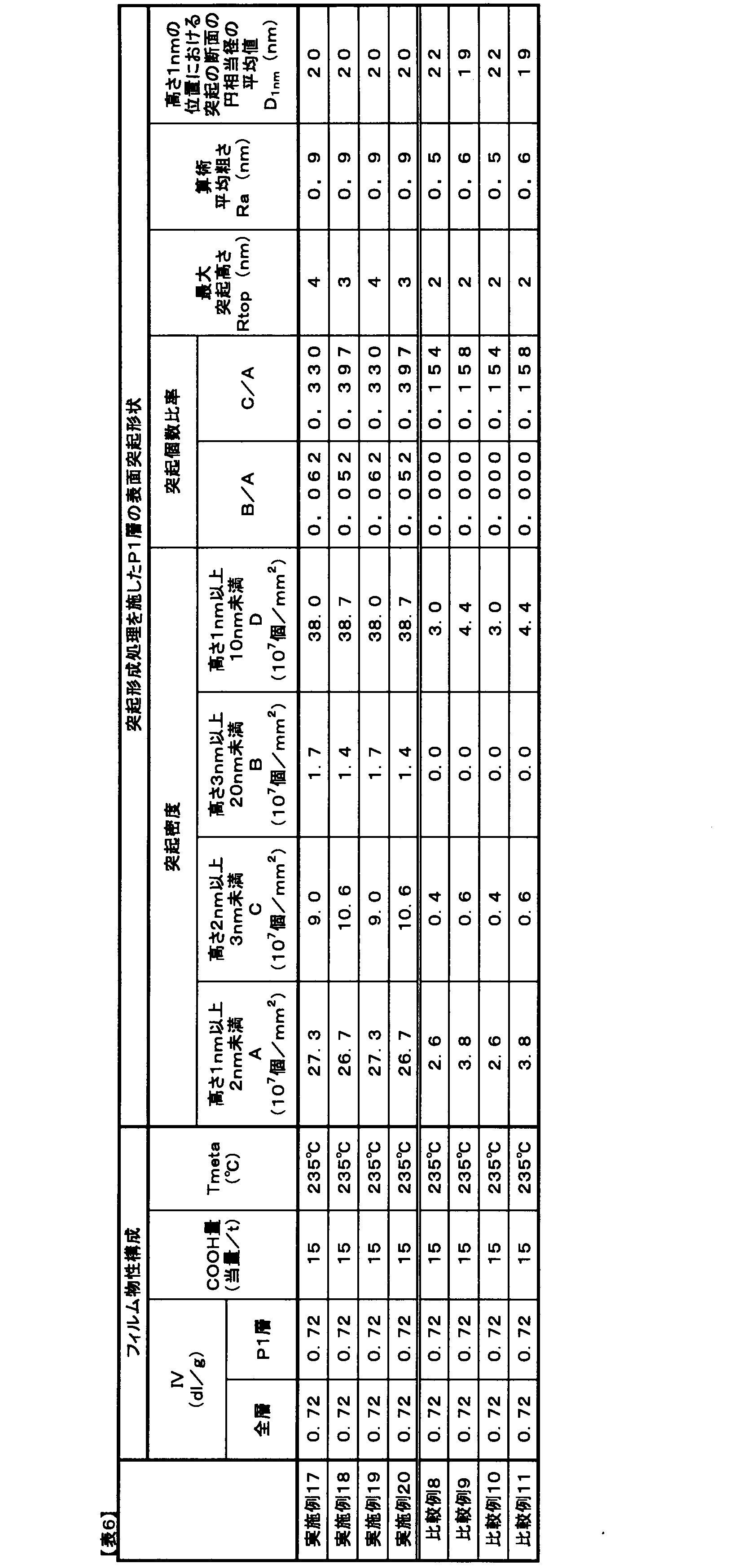

2.AFM解析における基準面(高さ0nm)
3.高さ1nm線(R1nm)
4.高さ2nm線(R2nm)
5.高さ3nm線(R3nm)
6.最大突起高さ(Rtop)
7.高さ20nm線(R20nm)
8.P2層
9.P3層
10.高さ1nmの位置における突起の断面
Claims (12)
- 少なくとも片側の表面が、最大突起高さが20nm未満であり、高さ1nm以上2nm未満の突起の個数をA(個/mm2)、高さ3nm以上20nm未満の突起の個数をB(個/mm2)とした場合に、B/Aが0.001以上5.000以下である二軸配向熱可塑性樹脂フィルム。
- 前記表面が、高さ2nm以上3nm未満の突起の個数をC(個/mm2)とした場合、C/Aが0.100以上2.000以下である請求項1に記載の二軸配向熱可塑性樹脂フィルム。
- 前記表面の算術平均粗さRaが3.0nm以下である請求項1または2に記載の二軸配向熱可塑性樹脂フィルム。
- 前記表面を有する層が実質的に粒子を含有しない請求項1~3のいずれかに記載の二軸配向熱可塑性樹脂フィルム。
- 前記表面の突起において高さ1nmにおける突起断面の円相当径の平均値が15nm以上30nm以下である請求項1~4のいずれかに記載の二軸配向熱可塑性樹脂フィルム。
- 前記高さ1nm以上2nm未満の突起の個数Aが1.0×10⁷個/mm2以上1.0×109個/mm2以下である請求項1~5のいずれかに記載の二軸配向熱可塑性樹脂フィルム。
- 前記表面の高さ1nm以上10nm未満の突起の個数をD(個/mm2)とした場合、突起個数Dが5.0×107~6.0×109個/mm2である請求項1~6のいずれかに記載の二軸配向熱可塑性樹脂フィルム。
- 前記二軸配向熱可塑性樹脂フィルムを構成する熱可塑性樹脂が、ポリエステル樹脂、ポリエチレン樹脂、ポリプロピレン樹脂、ポリフェニレンスルフィド樹脂、ポリイミド樹脂のいずれかを主成分とする請求項1~7のいずれかに記載の二軸配向熱可塑性樹脂フィルム。
- 離型用フィルムとして用いられる請求項1~8のいずれかに記載の二軸配向熱可塑性樹脂フィルム。
- ドライフィルムレジスト支持体用フィルムとして用いられる請求項1~8のいずれかに記載の二軸配向熱可塑性樹脂フィルム。
- 積層セラミックコンデンサーを製造する工程においてグリーンシート成形の支持体用フィルムとして用いられる請求項1~8のいずれかに記載の二軸配向熱可塑性樹脂フィルム。
- 磁気記録媒体用ベースフィルムに用いられる、請求項1~8のいずれかに記載の二軸配向熱可塑性樹脂フィルム。
Priority Applications (4)
| Application Number | Priority Date | Filing Date | Title |
|---|---|---|---|
| KR1020207013625A KR102596116B1 (ko) | 2017-12-20 | 2018-11-27 | 2축 배향 열 가소성 수지 필름 |
| JP2018563190A JP7247585B2 (ja) | 2017-12-20 | 2018-11-27 | 二軸配向熱可塑性樹脂フィルム |
| CN201880081984.7A CN111566148B (zh) | 2017-12-20 | 2018-11-27 | 双轴取向热塑性树脂膜 |
| MYPI2020003141A MY207660A (en) | 2017-12-20 | 2018-11-27 | Biaxially oriented thermoplastic resin film |
Applications Claiming Priority (4)
| Application Number | Priority Date | Filing Date | Title |
|---|---|---|---|
| JP2017243473 | 2017-12-20 | ||
| JP2017-243473 | 2017-12-20 | ||
| JP2018-161052 | 2018-08-30 | ||
| JP2018161052 | 2018-08-30 |
Publications (1)
| Publication Number | Publication Date |
|---|---|
| WO2019123990A1 true WO2019123990A1 (ja) | 2019-06-27 |
Family
ID=66994771
Family Applications (1)
| Application Number | Title | Priority Date | Filing Date |
|---|---|---|---|
| PCT/JP2018/043483 Ceased WO2019123990A1 (ja) | 2017-12-20 | 2018-11-27 | 二軸配向熱可塑性樹脂フィルム |
Country Status (6)
| Country | Link |
|---|---|
| JP (1) | JP7247585B2 (ja) |
| KR (1) | KR102596116B1 (ja) |
| CN (1) | CN111566148B (ja) |
| MY (1) | MY207660A (ja) |
| TW (1) | TWI791704B (ja) |
| WO (1) | WO2019123990A1 (ja) |
Cited By (9)
| Publication number | Priority date | Publication date | Assignee | Title |
|---|---|---|---|---|
| WO2020105471A1 (ja) * | 2018-11-19 | 2020-05-28 | 東レ株式会社 | 二軸配向熱可塑性樹脂フィルム |
| JP2020084187A (ja) * | 2018-11-19 | 2020-06-04 | 東レ株式会社 | ポリエステルフィルム |
| WO2021161816A1 (ja) * | 2020-02-12 | 2021-08-19 | 株式会社クレハ | 抗菌性成形体およびその製造方法 |
| JP2022156268A (ja) * | 2021-03-31 | 2022-10-14 | 大日本印刷株式会社 | 生物由来のポリエステルを使用した転写シート |
| WO2023027033A1 (ja) * | 2021-08-26 | 2023-03-02 | 富士フイルム株式会社 | ポリエステルフィルム、ポリエステルフィルムの製造方法、剥離フィルム |
| JP2023039591A (ja) * | 2021-09-09 | 2023-03-22 | 東レ株式会社 | 積層ポリエステルフィルム |
| WO2023120548A1 (ja) * | 2021-12-22 | 2023-06-29 | 三菱ケミカル株式会社 | ポリエステルフィルム及び積層ポリエステルフィルム |
| JP2024033378A (ja) * | 2022-08-30 | 2024-03-13 | 三菱ケミカル株式会社 | 積層ポリエステルフィルム |
| WO2025110124A1 (ja) * | 2023-11-20 | 2025-05-30 | 王子ホールディングス株式会社 | ポリプロピレンフィルム、金属層一体型ポリプロピレンフィルム、フィルムコンデンサ、及びフィルムロール |
Families Citing this family (2)
| Publication number | Priority date | Publication date | Assignee | Title |
|---|---|---|---|---|
| TWI746359B (zh) * | 2021-01-29 | 2021-11-11 | 南亞塑膠工業股份有限公司 | 聚酯薄膜及其製造方法 |
| CN115349178B (zh) * | 2021-03-12 | 2025-09-05 | 应用材料意大利有限公司 | 用于在用于生产太阳能电池的基板上印刷的方法和设备 |
Citations (6)
| Publication number | Priority date | Publication date | Assignee | Title |
|---|---|---|---|---|
| JPS6253815A (ja) * | 1985-09-02 | 1987-03-09 | Teijin Ltd | 金属薄膜磁気記録媒体用ポリエステルフイルム |
| JPS62282918A (ja) * | 1986-05-30 | 1987-12-08 | Toray Ind Inc | 磁気記録媒体用ポリエステルフイルム |
| WO2001066336A1 (fr) * | 2000-03-07 | 2001-09-13 | Toray Industries, Inc. | Film polyester et procede de production dudit film film polyester et procede de production dudit film |
| JP2003238706A (ja) * | 2002-02-22 | 2003-08-27 | Mitsubishi Polyester Film Copp | 離型フィルム用ポリエステルフィルム |
| WO2017221701A1 (ja) * | 2016-06-24 | 2017-12-28 | 東レ株式会社 | 二軸配向熱可塑性樹脂フィルム |
| JP2018053210A (ja) * | 2016-09-30 | 2018-04-05 | 株式会社クラレ | 複層体およびその製造方法、並びに複合体およびその製造方法 |
Family Cites Families (8)
| Publication number | Priority date | Publication date | Assignee | Title |
|---|---|---|---|---|
| JP2569853B2 (ja) * | 1990-01-11 | 1997-01-08 | 東レ株式会社 | 二軸配向熱可塑性樹脂フィルムおよびフィルムロール |
| TW385275B (en) * | 1996-08-29 | 2000-03-21 | Toray Industries | Aromatic polyamide-based resin molding, a process therefor and magnetic recording medium made from the molding |
| EP1473318A4 (en) * | 2002-01-10 | 2007-06-27 | Toray Industries | BIAXIALLY ORIENTED THERMOPLASTIC FOIL |
| KR20030070823A (ko) * | 2002-02-26 | 2003-09-02 | 도레이 가부시끼가이샤 | 자기기록매체용 폴리에스테르 필름, 자기기록테이프 및디지탈 기록장치 |
| JP4216698B2 (ja) | 2003-11-26 | 2009-01-28 | 帝人デュポンフィルム株式会社 | 磁気記録媒体用二軸配向ポリエステルフィルムおよび磁気記録媒体 |
| EP2495284B1 (en) * | 2009-10-28 | 2016-09-28 | Toray Industries, Inc. | Biaxially oriented polyester film |
| CN105324245B (zh) * | 2013-06-18 | 2017-03-15 | 东丽株式会社 | 脱模用双轴取向层合聚酯膜 |
| JP2016221853A (ja) | 2015-05-30 | 2016-12-28 | 三菱樹脂株式会社 | 積層ポリエステルフィルム |
-
2018
- 2018-11-27 JP JP2018563190A patent/JP7247585B2/ja active Active
- 2018-11-27 KR KR1020207013625A patent/KR102596116B1/ko active Active
- 2018-11-27 CN CN201880081984.7A patent/CN111566148B/zh active Active
- 2018-11-27 WO PCT/JP2018/043483 patent/WO2019123990A1/ja not_active Ceased
- 2018-11-27 MY MYPI2020003141A patent/MY207660A/en unknown
- 2018-12-11 TW TW107144549A patent/TWI791704B/zh active
Patent Citations (6)
| Publication number | Priority date | Publication date | Assignee | Title |
|---|---|---|---|---|
| JPS6253815A (ja) * | 1985-09-02 | 1987-03-09 | Teijin Ltd | 金属薄膜磁気記録媒体用ポリエステルフイルム |
| JPS62282918A (ja) * | 1986-05-30 | 1987-12-08 | Toray Ind Inc | 磁気記録媒体用ポリエステルフイルム |
| WO2001066336A1 (fr) * | 2000-03-07 | 2001-09-13 | Toray Industries, Inc. | Film polyester et procede de production dudit film film polyester et procede de production dudit film |
| JP2003238706A (ja) * | 2002-02-22 | 2003-08-27 | Mitsubishi Polyester Film Copp | 離型フィルム用ポリエステルフィルム |
| WO2017221701A1 (ja) * | 2016-06-24 | 2017-12-28 | 東レ株式会社 | 二軸配向熱可塑性樹脂フィルム |
| JP2018053210A (ja) * | 2016-09-30 | 2018-04-05 | 株式会社クラレ | 複層体およびその製造方法、並びに複合体およびその製造方法 |
Cited By (13)
| Publication number | Priority date | Publication date | Assignee | Title |
|---|---|---|---|---|
| WO2020105471A1 (ja) * | 2018-11-19 | 2020-05-28 | 東レ株式会社 | 二軸配向熱可塑性樹脂フィルム |
| JP2020084187A (ja) * | 2018-11-19 | 2020-06-04 | 東レ株式会社 | ポリエステルフィルム |
| JP7532762B2 (ja) | 2018-11-19 | 2024-08-14 | 東レ株式会社 | ポリエステルフィルム |
| JP7409646B2 (ja) | 2020-02-12 | 2024-01-09 | 国立研究開発法人宇宙航空研究開発機構 | 抗菌性成形体およびその製造方法 |
| CN114981339A (zh) * | 2020-02-12 | 2022-08-30 | 株式会社吴羽 | 抗菌性成型体及其制造方法 |
| JP2021127366A (ja) * | 2020-02-12 | 2021-09-02 | 株式会社クレハ | 抗菌性成形体およびその製造方法 |
| WO2021161816A1 (ja) * | 2020-02-12 | 2021-08-19 | 株式会社クレハ | 抗菌性成形体およびその製造方法 |
| JP2022156268A (ja) * | 2021-03-31 | 2022-10-14 | 大日本印刷株式会社 | 生物由来のポリエステルを使用した転写シート |
| WO2023027033A1 (ja) * | 2021-08-26 | 2023-03-02 | 富士フイルム株式会社 | ポリエステルフィルム、ポリエステルフィルムの製造方法、剥離フィルム |
| JP2023039591A (ja) * | 2021-09-09 | 2023-03-22 | 東レ株式会社 | 積層ポリエステルフィルム |
| WO2023120548A1 (ja) * | 2021-12-22 | 2023-06-29 | 三菱ケミカル株式会社 | ポリエステルフィルム及び積層ポリエステルフィルム |
| JP2024033378A (ja) * | 2022-08-30 | 2024-03-13 | 三菱ケミカル株式会社 | 積層ポリエステルフィルム |
| WO2025110124A1 (ja) * | 2023-11-20 | 2025-05-30 | 王子ホールディングス株式会社 | ポリプロピレンフィルム、金属層一体型ポリプロピレンフィルム、フィルムコンデンサ、及びフィルムロール |
Also Published As
| Publication number | Publication date |
|---|---|
| KR20200098493A (ko) | 2020-08-20 |
| TWI791704B (zh) | 2023-02-11 |
| KR102596116B1 (ko) | 2023-10-31 |
| JPWO2019123990A1 (ja) | 2020-10-22 |
| TW201927573A (zh) | 2019-07-16 |
| CN111566148B (zh) | 2022-12-02 |
| JP7247585B2 (ja) | 2023-03-29 |
| CN111566148A (zh) | 2020-08-21 |
| MY207660A (en) | 2025-03-10 |
Similar Documents
| Publication | Publication Date | Title |
|---|---|---|
| JP7247585B2 (ja) | 二軸配向熱可塑性樹脂フィルム | |
| JP7006269B2 (ja) | 二軸配向熱可塑性樹脂フィルム | |
| JP7375548B2 (ja) | 二軸配向熱可塑性樹脂フィルム | |
| JP7543808B2 (ja) | ポリエステルフィルム | |
| JP7848525B2 (ja) | ドライフィルムレジスト支持体用二軸配向ポリエステルフィルム | |
| JP2020147751A (ja) | ポリエステルフィルム | |
| JP6926617B2 (ja) | 二軸配向積層ポリエステルフィルムおよび磁気記録媒体 | |
| JP2017200761A (ja) | 二軸配向積層ポリエステルフィルムおよび磁気記録媒体 | |
| KR20020081353A (ko) | 폴리에스테르 필름 및 그 제조방법 | |
| JP5177096B2 (ja) | ポリエステルフィルム及びその製造方法 | |
| JP7283040B2 (ja) | 熱可塑性樹脂フィルム | |
| JP7172304B2 (ja) | 熱可塑性樹脂フィルム | |
| JP2024047656A (ja) | 二軸配向ポリエステルフィルムおよびその製造方法 | |
| CN119856119A (zh) | 干膜抗蚀剂用叠层聚酯膜 | |
| JP2003182010A (ja) | セラミックシート製造用離型フィルム及びフィルム積層体 | |
| WO2023190265A1 (ja) | 二軸配向ポリエステルフィルム | |
| JP2022053506A (ja) | 二軸配向ポリエステルフィルム | |
| JPH06128394A (ja) | 二軸配向フィルム | |
| JPH07144360A (ja) | 二軸配向フィルム |
Legal Events
| Date | Code | Title | Description |
|---|---|---|---|
| ENP | Entry into the national phase |
Ref document number: 2018563190 Country of ref document: JP Kind code of ref document: A |
|
| 121 | Ep: the epo has been informed by wipo that ep was designated in this application |
Ref document number: 18891980 Country of ref document: EP Kind code of ref document: A1 |
|
| ENP | Entry into the national phase |
Ref document number: 20207013625 Country of ref document: KR Kind code of ref document: A |
|
| NENP | Non-entry into the national phase |
Ref country code: DE |
|
| 122 | Ep: pct application non-entry in european phase |
Ref document number: 18891980 Country of ref document: EP Kind code of ref document: A1 |