WO2020129951A1 - 接着積層コア、その製造方法及び回転電機 - Google Patents
接着積層コア、その製造方法及び回転電機 Download PDFInfo
- Publication number
- WO2020129951A1 WO2020129951A1 PCT/JP2019/049316 JP2019049316W WO2020129951A1 WO 2020129951 A1 WO2020129951 A1 WO 2020129951A1 JP 2019049316 W JP2019049316 W JP 2019049316W WO 2020129951 A1 WO2020129951 A1 WO 2020129951A1
- Authority
- WO
- WIPO (PCT)
- Prior art keywords
- adhesive
- inorganic filler
- electromagnetic steel
- laminated core
- particle size
- Prior art date
- Legal status (The legal status is an assumption and is not a legal conclusion. Google has not performed a legal analysis and makes no representation as to the accuracy of the status listed.)
- Ceased
Links
Images


Classifications
-
- H—ELECTRICITY
- H01—ELECTRIC ELEMENTS
- H01F—MAGNETS; INDUCTANCES; TRANSFORMERS; SELECTION OF MATERIALS FOR THEIR MAGNETIC PROPERTIES
- H01F27/00—Details of transformers or inductances, in general
- H01F27/24—Magnetic cores
- H01F27/245—Magnetic cores made from sheets, e.g. grain-oriented
-
- H—ELECTRICITY
- H02—GENERATION; CONVERSION OR DISTRIBUTION OF ELECTRIC POWER
- H02K—DYNAMO-ELECTRIC MACHINES
- H02K1/00—Details of the magnetic circuit
- H02K1/06—Details of the magnetic circuit characterised by the shape, form or construction
- H02K1/22—Rotating parts of the magnetic circuit
- H02K1/28—Means for mounting or fastening rotating magnetic parts on to, or to, the rotor structures
-
- B—PERFORMING OPERATIONS; TRANSPORTING
- B32—LAYERED PRODUCTS
- B32B—LAYERED PRODUCTS, i.e. PRODUCTS BUILT-UP OF STRATA OF FLAT OR NON-FLAT, e.g. CELLULAR OR HONEYCOMB, FORM
- B32B15/00—Layered products comprising a layer of metal
- B32B15/04—Layered products comprising a layer of metal comprising metal as the main or only constituent of a layer, which is next to another layer of the same or of a different material
- B32B15/043—Layered products comprising a layer of metal comprising metal as the main or only constituent of a layer, which is next to another layer of the same or of a different material of metal
-
- B—PERFORMING OPERATIONS; TRANSPORTING
- B32—LAYERED PRODUCTS
- B32B—LAYERED PRODUCTS, i.e. PRODUCTS BUILT-UP OF STRATA OF FLAT OR NON-FLAT, e.g. CELLULAR OR HONEYCOMB, FORM
- B32B15/00—Layered products comprising a layer of metal
- B32B15/18—Layered products comprising a layer of metal comprising iron or steel
-
- B—PERFORMING OPERATIONS; TRANSPORTING
- B32—LAYERED PRODUCTS
- B32B—LAYERED PRODUCTS, i.e. PRODUCTS BUILT-UP OF STRATA OF FLAT OR NON-FLAT, e.g. CELLULAR OR HONEYCOMB, FORM
- B32B7/00—Layered products characterised by the relation between layers; Layered products characterised by the relative orientation of features between layers, or by the relative values of a measurable parameter between layers, i.e. products comprising layers having different physical, chemical or physicochemical properties; Layered products characterised by the interconnection of layers
- B32B7/04—Interconnection of layers
- B32B7/12—Interconnection of layers using interposed adhesives or interposed materials with bonding properties
- B32B7/14—Interconnection of layers using interposed adhesives or interposed materials with bonding properties applied in spaced arrangements, e.g. in stripes
-
- C—CHEMISTRY; METALLURGY
- C08—ORGANIC MACROMOLECULAR COMPOUNDS; THEIR PREPARATION OR CHEMICAL WORKING-UP; COMPOSITIONS BASED THEREON
- C08G—MACROMOLECULAR COMPOUNDS OBTAINED OTHERWISE THAN BY REACTIONS ONLY INVOLVING UNSATURATED CARBON-TO-CARBON BONDS
- C08G59/00—Polycondensates containing more than one epoxy group per molecule; Macromolecules obtained by polymerising compounds containing more than one epoxy group per molecule using curing agents or catalysts which react with the epoxy groups
- C08G59/18—Macromolecules obtained by polymerising compounds containing more than one epoxy group per molecule using curing agents or catalysts which react with the epoxy groups ; e.g. general methods of curing
- C08G59/40—Macromolecules obtained by polymerising compounds containing more than one epoxy group per molecule using curing agents or catalysts which react with the epoxy groups ; e.g. general methods of curing characterised by the curing agents used
- C08G59/62—Alcohols or phenols
- C08G59/621—Phenols
-
- C—CHEMISTRY; METALLURGY
- C09—DYES; PAINTS; POLISHES; NATURAL RESINS; ADHESIVES; COMPOSITIONS NOT OTHERWISE PROVIDED FOR; APPLICATIONS OF MATERIALS NOT OTHERWISE PROVIDED FOR
- C09J—ADHESIVES; NON-MECHANICAL ASPECTS OF ADHESIVE PROCESSES IN GENERAL; ADHESIVE PROCESSES NOT PROVIDED FOR ELSEWHERE; USE OF MATERIALS AS ADHESIVES
- C09J11/00—Features of adhesives not provided for in group C09J9/00, e.g. additives
- C09J11/02—Non-macromolecular additives
- C09J11/04—Non-macromolecular additives inorganic
-
- C—CHEMISTRY; METALLURGY
- C09—DYES; PAINTS; POLISHES; NATURAL RESINS; ADHESIVES; COMPOSITIONS NOT OTHERWISE PROVIDED FOR; APPLICATIONS OF MATERIALS NOT OTHERWISE PROVIDED FOR
- C09J—ADHESIVES; NON-MECHANICAL ASPECTS OF ADHESIVE PROCESSES IN GENERAL; ADHESIVE PROCESSES NOT PROVIDED FOR ELSEWHERE; USE OF MATERIALS AS ADHESIVES
- C09J163/00—Adhesives based on epoxy resins; Adhesives based on derivatives of epoxy resins
- C09J163/10—Epoxy resins modified by unsaturated compounds
-
- H—ELECTRICITY
- H01—ELECTRIC ELEMENTS
- H01F—MAGNETS; INDUCTANCES; TRANSFORMERS; SELECTION OF MATERIALS FOR THEIR MAGNETIC PROPERTIES
- H01F3/00—Cores, Yokes, or armatures
- H01F3/02—Cores, Yokes, or armatures made from sheets
-
- H—ELECTRICITY
- H01—ELECTRIC ELEMENTS
- H01F—MAGNETS; INDUCTANCES; TRANSFORMERS; SELECTION OF MATERIALS FOR THEIR MAGNETIC PROPERTIES
- H01F41/00—Apparatus or processes specially adapted for manufacturing or assembling magnets, inductances or transformers; Apparatus or processes specially adapted for manufacturing materials characterised by their magnetic properties
- H01F41/02—Apparatus or processes specially adapted for manufacturing or assembling magnets, inductances or transformers; Apparatus or processes specially adapted for manufacturing materials characterised by their magnetic properties for manufacturing cores, coils, or magnets
- H01F41/0206—Manufacturing of magnetic cores by mechanical means
- H01F41/0233—Manufacturing of magnetic circuits made from sheets
-
- H—ELECTRICITY
- H02—GENERATION; CONVERSION OR DISTRIBUTION OF ELECTRIC POWER
- H02K—DYNAMO-ELECTRIC MACHINES
- H02K1/00—Details of the magnetic circuit
- H02K1/04—Details of the magnetic circuit characterised by the material used for insulating the magnetic circuit or parts thereof
-
- H—ELECTRICITY
- H02—GENERATION; CONVERSION OR DISTRIBUTION OF ELECTRIC POWER
- H02K—DYNAMO-ELECTRIC MACHINES
- H02K1/00—Details of the magnetic circuit
- H02K1/06—Details of the magnetic circuit characterised by the shape, form or construction
- H02K1/12—Stationary parts of the magnetic circuit
- H02K1/18—Means for mounting or fastening magnetic stationary parts on to, or to, the stator structures
-
- H—ELECTRICITY
- H02—GENERATION; CONVERSION OR DISTRIBUTION OF ELECTRIC POWER
- H02K—DYNAMO-ELECTRIC MACHINES
- H02K1/00—Details of the magnetic circuit
- H02K1/06—Details of the magnetic circuit characterised by the shape, form or construction
- H02K1/22—Rotating parts of the magnetic circuit
- H02K1/28—Means for mounting or fastening rotating magnetic parts on to, or to, the rotor structures
- H02K1/30—Means for mounting or fastening rotating magnetic parts on to, or to, the rotor structures using intermediate parts, e.g. spiders
-
- H—ELECTRICITY
- H02—GENERATION; CONVERSION OR DISTRIBUTION OF ELECTRIC POWER
- H02K—DYNAMO-ELECTRIC MACHINES
- H02K15/00—Processes or apparatus specially adapted for manufacturing, assembling, maintaining or repairing of dynamo-electric machines
- H02K15/02—Processes or apparatus specially adapted for manufacturing, assembling, maintaining or repairing of dynamo-electric machines of stator or rotor bodies
-
- B—PERFORMING OPERATIONS; TRANSPORTING
- B21—MECHANICAL METAL-WORKING WITHOUT ESSENTIALLY REMOVING MATERIAL; PUNCHING METAL
- B21D—WORKING OR PROCESSING OF SHEET METAL OR METAL TUBES, RODS OR PROFILES WITHOUT ESSENTIALLY REMOVING MATERIAL; PUNCHING METAL
- B21D28/00—Shaping by press-cutting; Perforating
- B21D28/02—Punching blanks or articles with or without obtaining scrap; Notching
- B21D28/22—Notching the peripheries of circular blanks, e.g. laminations for dynamo-electric machines
-
- B—PERFORMING OPERATIONS; TRANSPORTING
- B32—LAYERED PRODUCTS
- B32B—LAYERED PRODUCTS, i.e. PRODUCTS BUILT-UP OF STRATA OF FLAT OR NON-FLAT, e.g. CELLULAR OR HONEYCOMB, FORM
- B32B2250/00—Layers arrangement
- B32B2250/05—5 or more layers
-
- B—PERFORMING OPERATIONS; TRANSPORTING
- B32—LAYERED PRODUCTS
- B32B—LAYERED PRODUCTS, i.e. PRODUCTS BUILT-UP OF STRATA OF FLAT OR NON-FLAT, e.g. CELLULAR OR HONEYCOMB, FORM
- B32B2255/00—Coating on the layer surface
- B32B2255/06—Coating on the layer surface on metal layer
-
- B—PERFORMING OPERATIONS; TRANSPORTING
- B32—LAYERED PRODUCTS
- B32B—LAYERED PRODUCTS, i.e. PRODUCTS BUILT-UP OF STRATA OF FLAT OR NON-FLAT, e.g. CELLULAR OR HONEYCOMB, FORM
- B32B2255/00—Coating on the layer surface
- B32B2255/20—Inorganic coating
-
- B—PERFORMING OPERATIONS; TRANSPORTING
- B32—LAYERED PRODUCTS
- B32B—LAYERED PRODUCTS, i.e. PRODUCTS BUILT-UP OF STRATA OF FLAT OR NON-FLAT, e.g. CELLULAR OR HONEYCOMB, FORM
- B32B2255/00—Coating on the layer surface
- B32B2255/26—Polymeric coating
-
- B—PERFORMING OPERATIONS; TRANSPORTING
- B32—LAYERED PRODUCTS
- B32B—LAYERED PRODUCTS, i.e. PRODUCTS BUILT-UP OF STRATA OF FLAT OR NON-FLAT, e.g. CELLULAR OR HONEYCOMB, FORM
- B32B2255/00—Coating on the layer surface
- B32B2255/28—Multiple coating on one surface
-
- B—PERFORMING OPERATIONS; TRANSPORTING
- B32—LAYERED PRODUCTS
- B32B—LAYERED PRODUCTS, i.e. PRODUCTS BUILT-UP OF STRATA OF FLAT OR NON-FLAT, e.g. CELLULAR OR HONEYCOMB, FORM
- B32B2307/00—Properties of the layers or laminate
- B32B2307/20—Properties of the layers or laminate having particular electrical or magnetic properties, e.g. piezoelectric
- B32B2307/202—Conductive
-
- B—PERFORMING OPERATIONS; TRANSPORTING
- B32—LAYERED PRODUCTS
- B32B—LAYERED PRODUCTS, i.e. PRODUCTS BUILT-UP OF STRATA OF FLAT OR NON-FLAT, e.g. CELLULAR OR HONEYCOMB, FORM
- B32B2307/00—Properties of the layers or laminate
- B32B2307/20—Properties of the layers or laminate having particular electrical or magnetic properties, e.g. piezoelectric
- B32B2307/208—Magnetic, paramagnetic
-
- B—PERFORMING OPERATIONS; TRANSPORTING
- B32—LAYERED PRODUCTS
- B32B—LAYERED PRODUCTS, i.e. PRODUCTS BUILT-UP OF STRATA OF FLAT OR NON-FLAT, e.g. CELLULAR OR HONEYCOMB, FORM
- B32B2457/00—Electrical equipment
-
- H—ELECTRICITY
- H02—GENERATION; CONVERSION OR DISTRIBUTION OF ELECTRIC POWER
- H02K—DYNAMO-ELECTRIC MACHINES
- H02K2213/00—Specific aspects, not otherwise provided for and not covered by codes H02K2201/00 - H02K2211/00
- H02K2213/03—Machines characterised by numerical values, ranges, mathematical expressions or similar information
-
- Y—GENERAL TAGGING OF NEW TECHNOLOGICAL DEVELOPMENTS; GENERAL TAGGING OF CROSS-SECTIONAL TECHNOLOGIES SPANNING OVER SEVERAL SECTIONS OF THE IPC; TECHNICAL SUBJECTS COVERED BY FORMER USPC CROSS-REFERENCE ART COLLECTIONS [XRACs] AND DIGESTS
- Y02—TECHNOLOGIES OR APPLICATIONS FOR MITIGATION OR ADAPTATION AGAINST CLIMATE CHANGE
- Y02T—CLIMATE CHANGE MITIGATION TECHNOLOGIES RELATED TO TRANSPORTATION
- Y02T10/00—Road transport of goods or passengers
- Y02T10/60—Other road transportation technologies with climate change mitigation effect
- Y02T10/64—Electric machine technologies in electromobility
Definitions
- the present invention relates to an adhesive laminated core, a method for manufacturing the same, and a rotating electric machine.
- the present application claims priority based on Japanese Patent Application No. 2018-235871 filed in Japan on December 17, 2018, and the content thereof is incorporated herein.
- Adhesive laminated cores used for motors, transformers, etc. have been known for some time.
- the adhesive laminated core has a structure in which a plurality of thin electromagnetic steel plates are laminated and integrated with an adhesive.
- the adhesive laminated core having poor flatness the adhesive laminated core may not erect, the adhesive laminated core may tilt, the accuracy of the adhesive laminated core may not be stable, and the magnetic characteristics of the adhesive laminated core may deteriorate.
- Patent Document 1 magnetic steel sheets are adhered to each other with an adhesive containing an epoxy resin and a rubber component, and an adhesive lamination in which the amount of the adhesive protruding from the outer peripheral portion of the magnetic steel sheets is suppressed.
- the core is proposed.
- the accuracy of the film thickness of the adhesive portion is improved.
- Patent Document 1 has room for improvement in further improving flatness and space factor.
- the present invention has been made in view of the above-mentioned circumstances, and an object of the present invention is to provide an adhesive laminated core capable of further improving flatness and space factor, a manufacturing method thereof, and a rotating electric machine.
- the high space factor of the adhesive laminated core means that the ratio of the electromagnetic steel sheet to the cross section in the laminating direction of the adhesive laminated core is high. This means that the magnetic field lines can be formed at a high density when the magnetic field lines are generated inside the adhesive laminated core by the excitation from the winding current. That is, increasing the space factor of the adhesive laminated core means increasing the magnetic characteristics of the adhesive laminated core.
- the inventors of the present invention determine the flatness of the adhesive laminated core by determining the 50% particle size (center particle size) of the inorganic filler and the average particle size of the inorganic filler (particle size of all particles of the inorganic filler). It was found that not only the arithmetic mean) but also the 90% particle size of the inorganic filler and the maximum particle size of the inorganic filler. That is, the present inventors have found that it is a component having a large particle size in the population of particles of the inorganic filler that determines the flatness of the adhesive laminated core.
- the present inventors have conducted extensive studies in order to solve the above problems. As a result, it is possible to further improve the flatness of the adhesive laminated core by reducing the 50% particle diameter of the inorganic filler contained in the adhesive portion and reducing the 90% particle diameter of the inorganic filler contained in the adhesive portion.
- the inventors have found that the space factor of the adhesive laminated core can be improved, and have completed the present invention. That is, the present invention has the following aspects.
- a first aspect of the present invention is provided between a plurality of electromagnetic steel sheets laminated on each other and coated with insulating coatings on both sides, and the electromagnetic steel sheets adjacent to each other in the laminating direction.
- Adhesive parts for adhering to each other wherein the adhesive forming the adhesive part contains an organic resin and an inorganic filler, and the 50% particle diameter of the inorganic filler is 0.2 to 3.5 ⁇ m.
- the adhesive laminated core has a 90% particle diameter of the filler of 10.0 ⁇ m or less and a content of the inorganic filler of 5 to 50 parts by mass with respect to 100 parts by mass of the organic resin.
- the maximum particle size of the inorganic filler may be 30.0 ⁇ m or less.
- the inorganic filler may contain one or more selected from metal oxides and metal hydroxides.
- the inorganic filler may contain one or more selected from aluminum hydroxide and aluminum oxide.
- the adhesive laminated core according to any one of (1) to (4) above may be for a stator.
- a third aspect of the present invention is a rotating electric machine including the adhesive laminated core according to any one of (1) to (5).
- the flatness can be further improved and the space factor can be improved.
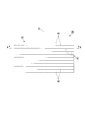
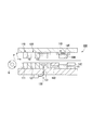
- FIG. 3 is a sectional view taken along line AA of FIG. 2. It is a side view which shows schematic structure of the manufacturing apparatus of an adhesion laminated core.
- an electric motor specifically, an AC motor, more specifically, a synchronous motor, and more specifically, a permanent magnet field type electric motor will be described as an example of the rotating electric machine.
- This type of electric motor is preferably used in, for example, an electric vehicle.
- the rotary electric machine 10 includes a stator 20, a rotor 30, a case 50, and a rotating shaft 60.
- the stator 20 and the rotor 30 are housed in the case 50.
- the stator 20 is fixed to the case 50.
- an inner rotor type in which the rotor 30 is located inside the stator 20 is adopted.
- the rotating electric machine 10 may be an outer rotor type in which the rotor 30 is located outside the stator 20.
- the rotary electric machine 10 is a 12-pole 18-slot three-phase AC motor. However, the number of poles, the number of slots, the number of phases, etc. can be changed appropriately.
- the rotating electrical machine 10 can rotate at a rotation speed of 1000 rpm, for example, by applying an exciting current having an effective value of 10 A and a frequency of 100 Hz to each phase.
- the stator 20 includes a stator core 21 and a winding (not shown).
- the stator core 21 includes an annular core back portion 22 and a plurality of teeth portions 23.
- the direction of the central axis O of the stator core 21 (or the core back portion 22) is referred to as the axial direction
- the radial direction of the stator core 21 (or the core back portion 22) (the direction orthogonal to the central axis O) is referred to as the radial direction
- the circumferential direction of the stator core 21 (or the core back portion 22) (direction around the central axis O thereof) is called the circumferential direction.
- the core back portion 22 is formed in an annular shape in a plan view when the stator 20 is viewed in the axial direction.
- the plurality of teeth portions 23 project from the core back portion 22 inward in the radial direction (toward the central axis O of the core back portion 22 along the radial direction).
- the plurality of tooth portions 23 are arranged at equal intervals in the circumferential direction.
- 18 teeth portions 23 are provided at a central angle of 20 degrees about the central axis O.
- the plurality of teeth portions 23 have the same shape and the same size.
- the winding is wound around the tooth portion 23.
- the winding may be concentrated winding or distributed winding.
- the rotor 30 is arranged radially inside the stator 20 (or the stator core 21).
- the rotor 30 includes a rotor core 31 and a plurality of permanent magnets 32.
- the rotor core 31 is formed in an annular shape (annular shape) arranged coaxially with the stator 20.
- the rotating shaft 60 is arranged in the rotor core 31.
- the rotating shaft 60 is fixed to the rotor core 31.
- the plurality of permanent magnets 32 are fixed to the rotor core 31. In the present embodiment, two pairs of permanent magnets 32 form one magnetic pole.
- the plurality of sets of permanent magnets 32 are arranged at equal intervals in the circumferential direction. In the present embodiment, 12 sets (24 in total) of permanent magnets 32 are provided at a central angle of 30 degrees about the central axis O.
- an embedded magnet type motor is adopted as the permanent magnet field type electric motor.
- the rotor core 31 is formed with a plurality of through holes 33 that penetrate the rotor core 31 in the axial direction.
- the plurality of through holes 33 are provided corresponding to the plurality of permanent magnets 32.
- Each permanent magnet 32 is fixed to the rotor core 31 while being arranged in the corresponding through hole 33.
- the fixing of each permanent magnet 32 to the rotor core 31 can be realized by, for example, bonding the outer surface of the permanent magnet 32 and the inner surface of the through hole 33 with an adhesive agent.
- a surface magnet type motor may be adopted as the permanent magnet field type electric motor instead of the embedded magnet type motor.
- the stator core 21 and the rotor core 31 are both adhesive laminated cores.
- the stator 20 is formed by stacking a plurality of electromagnetic steel plates 40.
- the adhesive portions 41 that adhere the electromagnetic steel plates 40 to each other are provided between the electromagnetic steel plates 40 that are adjacent to each other in the stacking direction, and the electromagnetic steel plates 40 are adhered to each other by the adhesive parts 41. That is, in the stator 20, the plurality of electromagnetic steel plates 40 forming the stator core 21 are laminated with the adhesive portion 41 interposed therebetween.
- the laminated thickness of each of the stator core 21 and the rotor core 31 is, for example, 50.0 mm.
- the outer diameter of the stator core 21 is, for example, 250.0 mm.
- the inner diameter of the stator core 21 is, for example, 165.0 mm.
- the outer diameter of the rotor core 31 is, for example, 163.0 mm.
- the inner diameter of the rotor core 31 is, for example, 30.0 mm.
- these values are examples, and the product thickness, outer diameter, and inner diameter of the stator core 21, and the product thickness, outer diameter, and inner diameter of the rotor core 31 are not limited to these values.
- the inner diameter of the stator core 21 is based on the tip of the tooth portion 23 of the stator core 21.
- the inner diameter of the stator core 21 is the diameter of an imaginary circle inscribed in the tips of all the teeth 23.
- Each electromagnetic steel plate 40 forming the stator core 21 and the rotor core 31 is formed, for example, by punching an electromagnetic steel plate serving as a base material.
- the electromagnetic steel plate 40 a known electromagnetic steel plate can be used.
- the chemical composition of the electromagnetic steel sheet 40 is not particularly limited.
- a non-oriented electrical steel sheet is used as the electrical steel sheet 40.
- a non-oriented electrical steel sheet for example, a non-oriented electrical steel strip according to JIS C2552:2014 can be adopted.
- the grain-oriented electrical steel sheet for example, a grain-oriented electrical steel strip according to JIS C2553:2012 can be adopted.
- both surfaces of the electromagnetic steel sheet 40 are covered with insulating coatings.
- the substance forming the insulating coating for example, (1) an inorganic compound, (2) an organic resin, (3) a mixture of an inorganic compound and an organic resin, or the like can be applied.
- the inorganic compound include (1) a composite of dichromate and boric acid, (2) a composite of phosphate and silica, and (3) phosphate.
- the organic resin include epoxy resin, acrylic resin, acrylic styrene resin, polyester resin, silicone resin, and fluororesin. The organic resin may be the same as or different from the organic resin contained in the adhesive described later.
- the thickness of the insulating coating is preferably 0.1 ⁇ m or more.
- the insulating effect becomes saturated as the insulating coating becomes thicker.
- the space factor decreases and the performance as the adhesive laminated core decreases. Therefore, the insulating coating is preferably thin as long as the insulating performance can be secured.
- the thickness of the insulating coating is preferably 0.1 ⁇ m or more and 5 ⁇ m or less, and more preferably 0.1 ⁇ m or more and 2 ⁇ m or less. The thickness of the insulating coating can be measured, for example, by observing a cut surface obtained by cutting the electromagnetic steel plate 40 in the thickness direction with a microscope or the like.
- the thickness of the electromagnetic steel sheet 40 is preferably 0.10 mm or more.
- the thickness of the electromagnetic steel plate 40 is preferably 0.65 mm or less. Further, as the electromagnetic steel plate 40 becomes thicker, iron loss increases.
- the thickness of the electromagnetic steel plate 40 is preferably 0.35 mm or less, more preferably 0.25 mm or less, and further preferably 0.20 mm or less.
- the thickness of each electromagnetic steel plate 40 is, for example, preferably 0.10 mm or more and 0.65 mm or less, more preferably 0.10 mm or more and 0.35 mm or less, and 0.10 mm or more and 0.25 mm or less. More preferably, 0.10 mm or more and 0.20 mm or less are particularly preferable.
- the thickness of the electromagnetic steel plate 40 also includes the thickness of the insulating coating. The thickness of the electromagnetic steel plate 40 can be measured by, for example, a micrometer or the like.
- a plurality of electromagnetic steel plates 40 forming the stator core 21 are laminated with an adhesive portion 41 interposed therebetween.
- the adhesive portion 41 is formed on the core back portion 22 and the tooth portion 23 of the stator core 21.
- the adhesive portion 41 is formed radially inward from the inner periphery of the core back portion 22 (toward the central axis O of the core back portion 22 along the radial direction) like 41 a, 41 b, and 41 c. ..
- Adhesive portions 41b and 41c are formed on the plurality of tooth portions 23, respectively.
- Adhesive portions 41a are formed on the core back portions 22 at positions corresponding to the plurality of tooth portions 23, respectively.
- the adhesive portion 41 is a layer formed of an adhesive containing an organic resin and an inorganic filler.
- the organic resin that constitutes the adhesive is not particularly limited, and examples thereof include polyolefin resin, acrylic resin, polyurethane resin, epoxy resin, polyamide resin, polyimide resin, polyester resin, silicone resin, and fluororesin.
- an acrylic-modified epoxy resin obtained by graft-polymerizing an acrylic resin with an epoxy resin is preferable from the viewpoint of easily increasing the adhesive strength of the adhesive portion 41.
- the epoxy resin for example, those obtained by condensing epichlorohydrin and bisphenol in the presence of an alkali catalyst, epichlorohydrin and bisphenol are condensed into a low molecular weight epoxy resin in the presence of an alkali catalyst, Examples thereof include those obtained by polyaddition reaction of a low molecular weight epoxy resin and bisphenol.
- the "low molecular weight epoxy resin” means an epoxy resin having a number average molecular weight of less than 1200.
- the epoxy resin may be an epoxy ester resin in which a divalent carboxylic acid is combined.
- Examples of the divalent carboxylic acid include succinic acid, adipic acid, himelic acid, azelaic acid, sebacic acid, dodecanedioic acid, and hexahydrophthalic acid.
- Examples of the bisphenol include bisphenol A, bisphenol F, bisphenol AD and the like, and bisphenol A and bisphenol F are preferable.
- Examples of the alkali catalyst include sodium hydroxide and potassium hydroxide. These epoxy resins may be used alone or in combination of two or more.
- the number average molecular weight of the epoxy resin is preferably 1200 to 8000, more preferably 2000 to 7000, still more preferably 2500 to 7000.
- the number average molecular weight of the epoxy resin can be measured by size exclusion chromatography (SEC: Size-Exclusion Chromatography) described in JIS K7252-1:2008 using polystyrene as a standard substance.
- the content of the epoxy resin is, for example, preferably 30 to 90% by mass, more preferably 40 to 80% by mass, and further preferably 50 to 70% by mass, based on the total mass of the adhesive.
- the content of the epoxy resin is at least the above lower limit, the adhesive strength of the adhesive portion 41 is likely to be increased.
- the content of the epoxy resin is less than or equal to the above upper limit value, the strain generated in the electrical steel sheet 40 can be easily relaxed.
- acrylic resin examples include acrylic resins obtained by polymerizing or copolymerizing at least one kind selected from unsaturated carboxylic acids such as acrylic acid, methacrylic acid, maleic acid, itaconic acid, crotonic acid, and the above unsaturated carboxylic acids.
- unsaturated carboxylic acids such as acrylic acid, methacrylic acid, maleic acid, itaconic acid, crotonic acid, and the above unsaturated carboxylic acids.
- An acrylic resin obtained by copolymerizing at least one kind of monomer selected from the following and at least one kind selected from the following radically polymerizable unsaturated monomers is mentioned.
- radical-polymerizable unsaturated monomer include (1) the number of carbon atoms of acrylic acid or methacrylic acid such as 2-hydroxyethyl acrylate, 2-hydroxyethyl methacrylate, hydroxypropyl acrylate and hydroxypropyl methacrylate.
- hydroxyalkyl esters (2) methyl acrylate, methyl methacrylate, ethyl acrylate, ethyl methacrylate, n-butyl acrylate, n-butyl methacrylate, isobutyl acrylate, isobutyl methacrylate, acrylic acid tert-butyl, tert-butyl methacrylate, cyclohexyl acrylate, cyclohexyl methacrylate, 2-ethylhexyl acrylate, 2-ethylhexyl methacrylate, lauryl acrylate, lauryl methacrylate, stearyl acrylate, stearyl methacrylate, decyl acrylate, etc.
- alkyl ester or cycloalkyl ester of acrylic acid or methacrylic acid having 1 to 24 carbon atoms (3) acrylamide, methacrylamide, N-methyl acrylamide, N-ethyl acrylamide, diacetone acrylamide, N-methylol acrylamide
- Aromatic vinyl monomer such as functional acrylamide or functional methacrylamide such as N, methylol methacrylamide, N-methoxymethyl acrylamide and N-butoxymethyl acrylamide, and (4) styrene, vinyltoluene, ⁇ -methylstyrene And (5) vinyl acetate, vinyl propionate, acrylonitrile, methacrylonitrile, and other aliphatic vinyl monomers.
- Preferred combinations of the above unsaturated monomers include, for example, a combination of methyl methacrylate, 2-ethylhexyl acrylate and acrylic acid, a combination of styrene, methyl methacrylate, ethyl acrylate and methacrylic acid, styrene and acrylic.
- examples include a combination of ethyl acid and methacrylic acid, a combination of methyl methacrylate, ethyl acrylate, and acrylic acid.
- the number average molecular weight of the acrylic resin is preferably 5,000 to 100,000, more preferably 6,000 to 80,000, and further preferably 7,000 to 60,000.
- the number average molecular weight of the acrylic resin is not less than the above lower limit value, the adhesive strength of the adhesive portion 41 is likely to be increased.
- the number average molecular weight of the acrylic resin is not more than the above upper limit value, it is easy to prevent the adhesive from becoming highly viscous, and it is easy to flatten the adhesive portion 41.
- the number average molecular weight of the acrylic resin can be measured by the same method as the number average molecular weight of the epoxy resin.
- the content of the acrylic resin is, for example, preferably 10 to 40% by mass, more preferably 15 to 35% by mass, and further preferably 20 to 30% by mass, based on the total mass of the adhesive.
- the adhesive strength of the adhesive portion 41 is likely to be increased.
- the content of the acrylic resin is less than or equal to the above upper limit value, it is easy to prevent the adhesive from having a high viscosity, and it is easy to flatten the adhesive portion 41. Therefore, it is easy to suppress the distortion of the adhesive laminated core.
- An acrylic-modified epoxy resin obtained by graft-polymerizing an acrylic resin with an epoxy resin is, for example, a high molecular weight epoxy resin in an organic solvent solution in the presence of a radical generator such as benzoyl peroxide. It is obtained by carrying out a graft polymerization reaction of the above radically polymerizable unsaturated monomer on a resin.
- the "high molecular weight epoxy resin” means an epoxy resin having a number average molecular weight of 1200 or more.
- the radical generator used in the graft polymerization reaction is preferably 3 to 15 parts by mass with respect to 100 parts by mass of the solid content of the radically polymerizable unsaturated monomer.
- the above graft polymerization reaction requires, for example, 1 to 3 hours with a radically polymerizable unsaturated monomer obtained by uniformly mixing a radical generator with an organic solvent solution of a high molecular weight epoxy resin heated to 80 to 150° C. And the same temperature is maintained for 1 to 3 hours.
- the organic solvent used in the graft polymerization reaction may be any organic solvent that dissolves the high molecular weight epoxy resin and the radically polymerizable unsaturated monomer and is miscible with water.
- organic solvent include isopropanol, butyl alcohol, 2-hydroxy-4-methylpentane, 2-ethylhexyl alcohol, cyclohexanol, ethylene glycol, diethylene glycol, 1,3-butylene glycol, ethylene glycol monoethyl ether, Examples thereof include alcohol solvents such as ethylene glycol monobutyl ether and diethylene glycol monomethyl ether, ketone solvents such as acetone and methyl ethyl ketone, cellosolve solvents and carbitol solvents.
- an inert organic solvent which is immiscible with water
- examples of such an organic solvent include aromatic hydrocarbons such as toluene and xylene, and esters such as ethyl acetate and butyl acetate. ..
- the curing agent may be a commonly used epoxy resin curing agent.
- the epoxy resin curing agent include polyamine curing agents such as aliphatic polyamines, alicyclic polyamines, aromatic polyamines, polyamide polyamines and modified polyamines; monofunctional acid anhydrides (phthalic anhydride, hexahydrophthalic anhydride, Methyl tetrahydro phthalic anhydride, methyl hexahydro phthalic anhydride, methyl nadic acid anhydride, chlorendic acid anhydride, etc.) Bifunctional acid anhydrides (pyromellitic acid anhydride, benzophenone tetracarboxylic acid anhydride, ethylene glycol bis(ane Hydrotrimate), methylcyclohexene tetracarboxylic acid anhydride, etc.), free acid acid anhydride (trimellitic anhydride, polyazelainic acid anhydride, etc.), etc.
- polyamine curing agents such as
- At least one selected from methylol group-containing initial condensates such as urea resins and melamine resins; latent curing agents and the like can be used.
- latent curing agent for example, dicyandiamide, melamine, organic acid dihydrazide, amine imide, ketimine, tertiary amine, imidazole salt, boron trifluoride amine salt, microcapsule type curing agent (the curing agent is formed with casein etc.
- a microcapsule which breaks the microcapsule when heated and pressed to cause a curing reaction with the resin
- a molecular sieve type curing agent a curing agent adsorbed on the surface of an adsorptive compound, an adsorption molecule by heating. And the like which react with the resin to cure).
- a novolac type phenol resin (phenol novolac resin) is preferable from the viewpoint of easily increasing the adhesive strength of the adhesive portion 41.
- the "novolak type phenolic resin” means a resin obtained by subjecting phenols and aldehydes to a condensation reaction using an acid catalyst. Examples of phenols include phenol. Formaldehyde is mentioned as an aldehyde. Examples of the acid catalyst include oxalic acid and divalent metal salts.
- the novolac type phenol resin is a solid at room temperature (25° C.) and is classified as a thermoplastic resin. In the novolac type phenol resin, the --CH 2 OH group is hardly bonded to the phenol nucleus (aromatic ring) that constitutes the phenol resin.
- the content of the epoxy resin curing agent is preferably 1 to 20% by mass based on the total mass of the adhesive.
- the content of the epoxy resin curing agent is at least the above lower limit value, it is easy to increase the adhesive strength of the adhesive portion 41.
- the content of the epoxy resin curing agent is less than or equal to the above upper limit, the stability of the adhesive portion 41 is likely to be increased.
- the adhesive may include an elastomer.
- the elastomer include natural rubber and synthetic rubber, and synthetic rubber is preferable.
- the synthetic rubber include polybutadiene synthetic rubber, nitrile synthetic rubber, chloroprene synthetic rubber and the like.
- the polybutadiene synthetic rubber include isoprene rubber (IR), butadiene rubber (BR), styrene butadiene rubber (SBR), polyisobutylene (butyl rubber, IIR), ethylene propylene diene rubber (EPDM) and the like.
- the nitrile synthetic rubber include acrylonitrile butadiene rubber (NBR) and acrylic rubber (ACM).
- chloroprene synthetic rubber examples include chloroprene rubber (CR) and the like.
- the synthetic rubber in addition to the above, urethane rubber, silicone rubber, fluororubber (FKM), chlorosulfonated polyethylene (CSM), epichlorohydrin rubber (ECO) and the like may be used.
- FKM fluororubber
- CSM chlorosulfonated polyethylene
- ECO epichlorohydrin rubber
- SBR, EPDM, and NBR are preferable because they have excellent heat resistance and can easily alleviate the strain generated in the electromagnetic steel plate 40.
- the elastomer may be used alone or in combination of two or more.
- the content of the elastomer is preferably 5 to 30% by mass with respect to the total mass of the adhesive.
- the content of the elastomer is equal to or more than the above lower limit value, the strain generated in the magnetic steel sheet 40 is easily relaxed.
- the content of the elastomer is less than or equal to the above upper limit value, the adhesive strength of the adhesive portion 41 is likely to be increased.
- the content of the organic resin is, for example, preferably 40 to 95% by mass, more preferably 50 to 90% by mass, and further preferably 60 to 80% by mass, based on the total mass of the adhesive.
- the content of the organic resin is equal to or more than the above lower limit value, it is easy to increase the adhesive strength of the adhesive portion 41.
- the content of the organic resin is less than or equal to the above upper limit, it is easy to prevent the adhesive from becoming highly viscous, and it is easy to flatten the adhesive portion 41. Therefore, it is easy to suppress the distortion of the adhesive laminated core.
- the inorganic filler examples include metal oxides such as aluminum oxide ( ⁇ -alumina), zinc oxide, titanium oxide, calcium oxide, magnesium oxide, iron oxide, tin oxide; aluminum hydroxide (gibbsite), calcium hydroxide, water.
- metal oxides such as aluminum oxide ( ⁇ -alumina), zinc oxide, titanium oxide, calcium oxide, magnesium oxide, iron oxide, tin oxide; aluminum hydroxide (gibbsite), calcium hydroxide, water.
- metal hydroxides such as magnesium oxide
- silicon-containing substances such as silica, diatomaceous earth, calcium silicate, and talc
- sulfates such as calcium sulfate, magnesium sulfate, and barium sulfate.
- the inorganic filler may be used alone or in combination of two or more. From the viewpoint of being inexpensive and easily available, the inorganic filler is preferably one or more selected from metal oxides and metal hydroxides, more preferably one or more selected from aluminum hydroxide and aluminum oxide, and aluminum hydroxide
- the 50% particle size of the inorganic filler is 0.2 to 3.5 ⁇ m, preferably 0.4 to 3.0 ⁇ m, and more preferably 0.6 to 2.5 ⁇ m.
- the 50% particle diameter of the inorganic filler is equal to or more than the above lower limit value, it is easy to suppress expansion and contraction of the adhesive portion 41.
- the 50% particle size of the inorganic filler is not more than the above upper limit value, the space factor of the adhesive laminated core is likely to be increased.
- the 50% particle size of the inorganic filler is preferably 1.0 to 3.5 ⁇ m, more preferably 1.5 to 3.2 ⁇ m, and further preferably 2.0 to 3.0 ⁇ m.
- the 50% particle size of the inorganic filler is preferably 0.2 to 3.0 ⁇ m, more preferably 0.5 to 2.5 ⁇ m, still more preferably 1.0 to 2.0 ⁇ m. ..
- the 90% particle size of the inorganic filler is 10.0 ⁇ m or less, preferably 8.0 ⁇ m or less, and more preferably 6.0 ⁇ m or less.
- the lower limit of the 90% particle size of the inorganic filler is not particularly limited, but is substantially 2.0 ⁇ m.
- the 90% particle size of the inorganic filler is preferably 10.0 ⁇ m or less, more preferably 9.5 ⁇ m or less, and further preferably 9.0 ⁇ m or less.
- the 90% particle size of the inorganic filler is preferably 9.0 ⁇ m or less, more preferably 8.0 ⁇ m or less, and further preferably 7.0 ⁇ m or less.
- 50% particle size and 90% particle size represent volume-based particle sizes in the cumulative particle size distribution.
- the 50% particle size and the 90% particle size can be measured using a laser diffraction/scattering particle size distribution analyzer.
- the 50% particle size represents the particle size when the cumulative amount thereof accounts for 50% on a volume basis in the cumulative particle size curve of the particle size distribution measured using a laser diffraction/scattering type particle size distribution measuring device.
- the 90% particle size represents the particle size when the cumulative amount thereof accounts for 90% on a volume basis in the cumulative particle size curve of the particle size distribution measured using a laser diffraction/scattering type particle size distribution measuring device.
- the 90% particle size of the inorganic filler can be adjusted by passing it through a sieve with a specific opening or by a wind classification method.
- the maximum particle size of the inorganic filler is preferably 30.0 ⁇ m or less, more preferably 20.0 ⁇ m or less, still more preferably 10.0 ⁇ m or less.
- the lower limit of the maximum particle size of the inorganic filler is not particularly limited, but is substantially 3.0 ⁇ m.
- the maximum particle size of the inorganic filler is preferably 20.0 ⁇ m or less, more preferably 15.0 ⁇ m or less, and further preferably 10.0 ⁇ m or less.
- the maximum particle size of the inorganic filler is preferably 15.0 ⁇ m or less, more preferably 10.0 ⁇ m or less, and further preferably 8.0 ⁇ m or less.
- the maximum particle size of the inorganic filler can be measured using a laser diffraction/scattering type particle size distribution measuring device.
- the maximum particle size of the inorganic filler is given by the maximum value of all particles measured using a laser diffraction/scattering type particle size distribution measuring device.
- the maximum particle size of the inorganic filler can be adjusted by passing it through a sieve having a specific opening or by a wind classification method.
- the content of the inorganic filler is 5 to 50 parts by mass, preferably 5 to 40 parts by mass, more preferably 5 to 30 parts by mass, and further preferably 10 to 30 parts by mass with respect to 100 parts by mass of the organic resin.
- the content of the inorganic filler is at least the above lower limit value, it is easy to suppress expansion and contraction of the adhesive portion 41.
- the content of the inorganic filler is less than or equal to the above upper limit value, the space factor of the adhesive laminated core is likely to be increased.
- the content of the inorganic filler is a metal oxide
- the content of the inorganic filler is preferably 10 to 50 parts by mass, more preferably 15 to 40 parts by mass, and further preferably 20 to 30 parts by mass with respect to 100 parts by mass of the organic resin.
- the content of the inorganic filler is preferably 5 to 45 parts by mass, more preferably 10 to 40 parts by mass, and further preferably 15 to 35 parts by mass with respect to 100 parts by mass of the organic resin. preferable.
- the adhesive of the present embodiment may contain optional components in addition to the organic resin and the inorganic filler.
- a conductive substance an anticorrosive additive such as a poorly soluble chromate, a coloring pigment (for example, a condensed polycyclic organic pigment, a phthalocyanine organic pigment, etc.), a coloring dye (for example, an azo dye, an azo Metal complex salt dyes, etc.), film forming aids, dispersibility improvers, defoamers and the like.
- an anticorrosive additive such as a poorly soluble chromate
- a coloring pigment for example, a condensed polycyclic organic pigment, a phthalocyanine organic pigment, etc.
- a coloring dye for example, an azo dye, an azo Metal complex salt dyes, etc.
- film forming aids for example, an azo dye, an azo Metal complex salt dyes, etc.
- dispersibility improvers defoamers and the like.
- the content of the optional components is preferably 1 to 10 parts by mass with respect to 100 parts by mass of the organic resin.
- thermosetting adhesives in addition to thermosetting adhesives, radical polymerization adhesives and the like can also be used, and from the viewpoint of productivity, it is desirable to use room temperature curing adhesives. ..
- the room temperature curable adhesive cures at 20°C to 30°C.
- An acrylic adhesive is preferable as the room temperature curable adhesive.
- Typical acrylic adhesives include SGA (Second Generation Acrylic Adhesive. Second Generation Acrylic Adhesive). Any anaerobic adhesive, instant adhesive, or elastomer-containing acrylic adhesive can be used as long as the effects of the present invention are not impaired. It should be noted that the adhesive referred to here is in a state before being cured, and becomes an adhesive portion 41 after the adhesive is cured.
- the average tensile elastic modulus E of the adhesive portion 41 at room temperature (20° C. to 30° C.) is in the range of 1500 MPa to 4500 MPa. If the average tensile elastic modulus E of the adhesive portion 41 is less than 1500 MPa, the rigidity of the laminated core is reduced. Therefore, the lower limit of the average tensile elastic modulus E of the adhesive portion 41 is set to 1500 MPa, more preferably 1800 MPa. On the contrary, if the average tensile elastic modulus E of the adhesive portion 41 exceeds 4500 MPa, the insulating coating formed on the surface of the electromagnetic steel plate 40 may be peeled off.
- the upper limit value of the average tensile elastic modulus E of the adhesive portion 41 is set to 4500 MPa, more preferably 3650 MPa.
- the average tensile elastic modulus E is measured by the resonance method. Specifically, the tensile elastic modulus is measured according to JIS R 1602:1995. More specifically, first, a sample for measurement (not shown) is manufactured. This sample is obtained by bonding the two electromagnetic steel plates 40 together with an adhesive to be measured and curing it to form the bonding portion 41.
- the adhesive is a thermosetting type
- this curing is performed by heating and pressing under the heating and pressing conditions in actual operation.
- the adhesive is a room temperature curing type, it is performed by applying pressure at room temperature.
- the tensile elastic modulus of this sample is measured by the resonance method.
- the method of measuring the tensile elastic modulus by the resonance method is performed in accordance with JIS R 1602:1995, as described above.
- the tensile elastic modulus of the bonded portion 41 alone is obtained by calculating the influence of the electromagnetic steel plate 40 itself from the tensile elastic modulus (measured value) of the sample. Since the tensile modulus obtained from the sample in this way is equal to the average value of the laminated core as a whole, this value is regarded as the average tensile modulus E.
- the composition of the average tensile elastic modulus E is set so that the average tensile elastic modulus E hardly changes at the laminating position along the laminating direction or the circumferential position around the central axis of the laminated core. Therefore, the average tensile elastic modulus E can be set to the value obtained by measuring the cured adhesive portion 41 at the upper end position of the laminated core.
- a bonding method for example, a method of applying an adhesive to the electromagnetic steel plate 40 and then bonding by heating or pressure bonding or both can be adopted.
- the heating means may be any means such as heating in a high temperature tank or an electric furnace, or a method of directly energizing.
- the thickness of the adhesive portion 41 is preferably 1 ⁇ m or more.
- the thickness of the adhesive portion 41 exceeds 100 ⁇ m, the adhesive force is saturated. Further, as the adhesive portion 41 becomes thicker, the space factor decreases, and the magnetic characteristics such as iron loss of the adhesive laminated core deteriorate. Therefore, the thickness of the adhesive portion 41 is preferably 1 ⁇ m or more and 100 ⁇ m or less, and more preferably 1 ⁇ m or more and 10 ⁇ m or less. In the above, the thickness of the adhesive portion 41 means the average thickness of the adhesive portion 41.
- the average thickness of the adhesive portion 41 is more preferably 1.0 ⁇ m or more and 3.0 ⁇ m or less. If the average thickness of the adhesive portion 41 is less than 1.0 ⁇ m, sufficient adhesive force cannot be secured as described above. Therefore, the lower limit of the average thickness of the adhesive portion 41 is 1.0 ⁇ m, and more preferably 1.2 ⁇ m. On the contrary, if the average thickness of the adhesive portion 41 exceeds 3.0 ⁇ m and becomes thicker, a problem such as a large increase in the amount of distortion of the electrical steel sheet 40 due to shrinkage during thermosetting occurs. Therefore, the upper limit of the average thickness of the adhesive portion 41 is 3.0 ⁇ m, and more preferably 2.6 ⁇ m.
- the average thickness of the adhesive portion 41 is an average value of the entire adhesive laminated core.
- the average thickness of the adhesive portion 41 hardly changes at the laminating position along the laminating direction and the circumferential position around the central axis of the adhesive laminated core. Therefore, the average thickness of the adhesive portion 41 can be set to the average value of the numerical values measured at 10 or more positions in the circumferential direction at the upper end position of the adhesive laminated core.
- the average thickness of the adhesive portion 41 can be adjusted, for example, by changing the amount of adhesive applied. Also, the average tensile elastic modulus E of the adhesive portion 41, for example, in the case of a thermosetting adhesive, can be adjusted by changing one or both of the heating and pressurizing conditions and the type of curing agent applied at the time of adhesion. You can
- the plurality of electromagnetic steel plates 40 forming the rotor core 31 are fixed to each other by caulking C (dowel). However, the plurality of electromagnetic steel plates 40 forming the rotor core 31 may be bonded to each other by the bonding portion 41.
- the adhesive laminated cores such as the stator core 21 and the rotor core 31 may be formed by so-called rolling.
- the stator core 21 can be manufactured by applying an adhesive to a part of the surface of the electromagnetic steel plate 40, then stacking the adhesive on another electromagnetic steel plate, press-bonding the adhesive, and repeating the operation of forming the adhesive portion 41.
- the manufacturing apparatus 100 While feeding the original steel plate P from the coil Q (hoop) in the direction of arrow F, punching is performed a plurality of times by the die arranged on each stage to gradually form the shape of the electromagnetic steel plate 40. Adhesive is applied to predetermined positions on the lower surface of the second and subsequent electromagnetic steel plates 40, and the punched electromagnetic steel plates 40 are sequentially laminated and pressure-bonded.
- the manufacturing apparatus 100 has a first-stage punching station 110 at a position closest to the coil Q, and a second punching station 110 adjacent to the punching station 110 on the downstream side of the punching station 110 in the transport direction of the original steel sheet P.
- the punching station 120 at the first stage and the adhesive applying station 130 adjacently arranged on the downstream side of the punching station 120 are provided.
- the punching station 110 includes a female die 111 arranged below the original steel plate P and a male die 112 arranged above the original steel plate P.
- the punching station 120 includes a female die 121 arranged below the original steel plate P and a male die 122 arranged above the original steel plate P.
- the adhesive application station 130 includes an applicator 131 including a plurality of injectors arranged according to the adhesive application pattern.
- the manufacturing apparatus 100 further includes a laminating station 140 at a position downstream of the adhesive application station 130.
- the laminating station 140 includes a heating device 141, an outer peripheral punching female mold 142, a heat insulating member 143, an outer peripheral punching male mold 144, and a spring 145.
- the heating device 141, the outer peripheral punching female die 142, and the heat insulating member 143 are arranged below the original steel plate P.
- the outer peripheral punching male die 144 and the spring 145 are arranged above the original steel plate P.
- the original steel plate P is sequentially sent out from the coil Q in the direction of arrow F in FIG. Then, the original steel sheet P is first punched by the punching station 110. Then, the original steel sheet P is punched by the punching station 120.
- the shape of the electromagnetic steel sheet 40 having the core back portion 22 and the plurality of teeth portions 23 shown in FIG. 3 is obtained on the original steel sheet P (punching step).
- the adhesive application station 130 in the next step the adhesive supplied from each injector of the applicator 131 is applied in a dot shape (application step).
- the original steel sheet P is sent to the laminating station 140, punched by the outer peripheral punching male die 144, and laminated accurately (laminating step).
- the electromagnetic steel plate 40 is subjected to a constant pressing force by the spring 145.
- the punching process, the coating process, and the laminating process as described above a predetermined number of electromagnetic steel plates 40 can be stacked.
- the iron core formed by stacking the electromagnetic steel plates 40 in this way is heated to, for example, 60 to 200° C. by the heating device 141. This heating cures the adhesive and forms the adhesive portion 41 (curing step).
- the stator core 21 is completed through the above steps.
- the rotating electrical machine and the adhesive laminated core according to the present embodiment are formed by laminating a plurality of electromagnetic steel sheets whose both surfaces are coated with the insulating coating, and the organic resin and the inorganic material are between the electromagnetic steel sheets adjacent to each other in the laminating direction. Adhesion is made at an adhesion part formed of an adhesive containing a filler. Adhesion between the electromagnetic steel sheets makes it possible to obtain sufficient adhesive strength. Since the adhesive portion contains the inorganic filler, expansion and contraction of the adhesive portion can be suppressed.
- an inorganic filler having a 50% particle diameter of 0.2 to 3.5 ⁇ m and a 90% particle diameter of 10.0 ⁇ m or less is added to 5 parts by weight of the organic resin. Includes up to 50 parts by mass. Therefore, in the rotary electric machine and the adhesive laminated core according to the present embodiment, it is easy to reduce the gap between the electromagnetic steel plates. As a result, the flatness of the adhesive laminated core can be further improved and the space factor of the adhesive laminated core can be increased. The adhesive laminated core according to this embodiment can further improve the flatness and the space factor. Therefore, the adhesive laminated core according to the present embodiment is suitable as an adhesive laminated core (stator core) for a stator. The adhesive laminated core may be used as a rotor core.
- the shape of the stator core is not limited to the shape shown in the above embodiment. Specifically, the outer diameter and inner diameter of the stator core, the product thickness, the number of slots, the circumferential and radial dimension ratios of the teeth portion 23, the radial dimension ratios of the teeth portion 23 and the core back portion 22, and the like are It can be arbitrarily designed according to the desired characteristics of the rotary electric machine.
- the pair of permanent magnets 32 forms one magnetic pole, but the present invention is not limited to this.
- one permanent magnet 32 may form one magnetic pole, and three or more permanent magnets 32 may form one magnetic pole.
- the rotating electric machine has been described by taking a permanent magnet field type electric motor as an example, but the structure of the rotating electric machine is not limited to this as illustrated below, and further various publicly known not illustrated below. The structure of can also be adopted.
- the permanent magnet field type motor is described as an example of the synchronous motor, but the present invention is not limited to this.
- the rotating electric machine may be a reluctance type electric motor or an electromagnet field type electric motor (winding field type electric motor).
- the synchronous motor is described as an example of the AC motor, but the present invention is not limited to this.
- the rotating electric machine may be an induction motor.
- the AC motor is described as an example of the electric motor, but the present invention is not limited to this.
- the rotating electric machine may be a DC electric motor.
- an electric motor has been described as an example of the rotating electric machine, but the present invention is not limited to this.
- the rotating electric machine may be a generator.
- Examples 1 to 6, Comparative Examples 1 to 4 Prepare a hoop with a thickness of 0.25 mm, apply an insulating film treatment solution containing a metal phosphate and an acrylic resin emulsion on both sides of this hoop, and bake at 300°C to obtain an insulating film of 0.8 ⁇ m on one side. Formed. The hoop having the insulating coating formed thereon was wound up to form a coil Q. The coil Q was set in the above-described manufacturing apparatus 100, and the original steel plate P was sent out from the coil Q in the arrow F direction.
- a single plate (electromagnetic steel plate 40) having a ring shape with an outer diameter of 300 mm and an inner diameter of 240 mm and having 18 rectangular teeth portions having a length of 30 mm and a width of 15 mm on the inner diameter side is punched out.
- the adhesive having the composition shown in Table 1 was applied in a dot shape at 5 mg per location at each position shown in FIG. 3 (application step), and laminated (lamination). Process).
- a laminated body in which 130 electromagnetic steel sheets were laminated was obtained.
- the obtained laminated body was heated at 120° C. while being pressurized at a pressure of 10 MPa, and the adhesive was cured (curing step) to manufacture the adhesive laminated core of each example.
- A1 Aluminum hydroxide (50% particle size 1.5 ⁇ m, 90% particle size 6.5 ⁇ m, maximum particle size 7.0 ⁇ m).
- A2 Aluminum oxide (50% particle size 2.5 ⁇ m, 90% particle size 8.5 ⁇ m, maximum particle size 9.5 ⁇ m).
- A′1 Silicon dioxide (50% particle size 1.5 ⁇ m, 90% particle size 12.0 ⁇ m, maximum particle size 15.0 ⁇ m).
- A′2 Magnesium oxide (50% particle size 2.5 ⁇ m, 90% particle size 15.5 ⁇ m, maximum particle size 21.0 ⁇ m).
- the space factor (%) of the obtained adhesive laminated core of each example was calculated.
- the space factor of the adhesive laminated core is given by the following formula.
- Space factor (%) M/(D ⁇ h ⁇ S) ⁇ 100
- M is the mass (kg) of the adhesive laminated core
- D is the density (kg/m 3 ) of the steel sheet (electromagnetic steel sheet excluding the insulating coating)
- h is the average height (m) of the adhesive laminated core
- S is the plane. It represents the area (m 2 ) of the electromagnetic steel sheet as viewed.
- the area S of the electromagnetic steel sheet was obtained by capturing the electromagnetic steel sheet before lamination as an image with a scanner and performing image analysis.
- the space factor was evaluated based on the following evaluation criteria. The results are shown in Table 1. "Evaluation criteria" A: The space factor is 99% or more. B: The space factor is 98% or more and less than 99%. C: The space factor is less than 98%.
- the adhesive laminated core of the present invention can further improve the flatness and the space factor.
- the flatness of the adhesive laminated core can be further improved and the space factor can be improved. Therefore, industrial availability is great.
- stator 10 rotating electric machine 20 stator 21 stator core (adhesive laminated core) 40 Electromagnetic steel plate 41 Adhesive part
Landscapes
- Engineering & Computer Science (AREA)
- Power Engineering (AREA)
- Manufacturing & Machinery (AREA)
- Chemical & Material Sciences (AREA)
- Organic Chemistry (AREA)
- Inorganic Chemistry (AREA)
- Chemical Kinetics & Catalysis (AREA)
- Medicinal Chemistry (AREA)
- Polymers & Plastics (AREA)
- Health & Medical Sciences (AREA)
- Adhesives Or Adhesive Processes (AREA)
- Iron Core Of Rotating Electric Machines (AREA)
- Laminated Bodies (AREA)
- Manufacture Of Motors, Generators (AREA)
- Manufacturing Cores, Coils, And Magnets (AREA)
Abstract
Description
本願は、2018年12月17日に、日本に出願された特願2018-235871号に基づき優先権を主張し、その内容をここに援用する。
接着部の膨張を抑制することで、接着積層コアの占積率を向上しやすい。接着積層コアの占積率が高いという事は、接着積層コアの積層方向の断面に占める電磁鋼板の割合が高いことを意味する。この事は、巻線電流からの励磁により、接着積層コアの内部に磁力線を発生させる際に高い密度で磁力線を形成できることを意味する。すなわち、接着積層コアの占積率を高めることは、接着積層コアの磁気特性を高めることを意味する。
しかし、本発明者等は、接着積層コアの平坦性を決めるのは、無機フィラーの50%粒径(中心粒径)や、無機フィラーの平均粒径(無機フィラーの全ての粒子の粒子径の算術平均)だけではなく、無機フィラーの90%粒径や、無機フィラーの最大粒径であることを見出した。すなわち、本発明者等は、接着積層コアの平坦性を決めるのは、無機フィラーの粒子の母集団において、粒径の大きな成分であることを見出した。
これは、無機フィラーの50%粒径や平均粒径がいくら小さくても、無機フィラーの粒子の母集団の中に「粗大な粒子」が存在すると、その粗大な粒子が電磁鋼板間の空隙(ギャップ)を支配するためであると考えられる。
すなわち、本発明は、以下の態様を有する。
(2)前記(1)に記載の接着積層コアでは、前記無機フィラーの最大粒径が30.0μm以下であってもよい。
(3)前記(1)又は前記(2)に記載の接着積層コアでは、前記無機フィラーが、金属酸化物及び金属水酸化物から選ばれる1種以上を含有していてもよい。
(4)前記(1)から前記(3)のいずれか1つに記載の接着積層コアでは、前記無機フィラーが、水酸化アルミニウム及び酸化アルミニウムから選ばれる1種以上を含有していてもよい。
(5)前記(1)から前記(4)のいずれか1つに記載の接着積層コアは、ステータ用であってもよい。
ステータ20は、ケース50に固定される。
本実施形態では、回転電機10として、ロータ30がステータ20の内側に位置するインナーロータ型を採用している。しかしながら、回転電機10として、ロータ30がステータ20の外側に位置するアウターロータ型を採用してもよい。また、本実施形態では、回転電機10が、12極18スロットの三相交流モータである。しかしながら、極数やスロット数、相数等は適宜変更することができる。
回転電機10は、例えば、各相に実効値10A、周波数100Hzの励磁電流を印加することにより、回転数1000rpmで回転することができる。
ステータコア21は、環状のコアバック部22と、複数のティース部23と、を備える。以下では、ステータコア21(又はコアバック部22)の中心軸線O方向を軸方向といい、ステータコア21(又はコアバック部22)の径方向(中心軸線Oに直交する方向)を径方向といい、ステータコア21(又はコアバック部22)の周方向(の中心軸線O周りに周回する方向)を周方向という。
複数のティース部23は、コアバック部22から径方向の内側に向けて(径方向に沿ってコアバック部22の中心軸線Oに向けて)突出する。複数のティース部23は、周方向に同等の間隔をあけて配置されている。本実施形態では、中心軸線Oを中心とする中心角20度おきに18個のティース部23が設けられている。複数のティース部23は、互いに同等の形状で、かつ同等の大きさに形成されている。
前記巻線は、ティース部23に巻き回されている。前記巻線は、集中巻きされていてもよく、分布巻きされていてもよい。
ロータコア31は、ステータ20と同軸に配置される環状(円環状)に形成されている。ロータコア31内には、前記回転軸60が配置されている。回転軸60は、ロータコア31に固定されている。
複数の永久磁石32は、ロータコア31に固定されている。本実施形態では、2つ1組の永久磁石32が1つの磁極を形成している。複数組の永久磁石32は、周方向に同等の間隔をあけて配置されている。本実施形態では、中心軸線Oを中心とする中心角30度おきに12組(全体では24個)の永久磁石32が設けられている。
ロータコア31には、ロータコア31を軸方向に貫通する複数の貫通孔33が形成されている。複数の貫通孔33は、複数の永久磁石32に対応して設けられている。各永久磁石32は、対応する貫通孔33内に配置された状態でロータコア31に固定されている。各永久磁石32のロータコア31への固定は、例えば永久磁石32の外面と貫通孔33の内面とを接着剤により接着すること等により、実現することができる。なお、永久磁石界磁型電動機として、埋込磁石型モータに代えて表面磁石型モータを採用してもよい。
ステータ20では、積層方向に隣り合う電磁鋼板40同士の間に、これらの電磁鋼板40同士を接着する接着部41が設けられ、それぞれの電磁鋼板40が、接着部41により接着されている。つまり、ステータ20において、ステータコア21を形成する複数の電磁鋼板40は、接着部41を介して積層されている。
しかしながら、電磁鋼板40として、無方向性電磁鋼板に代えて方向性電磁鋼板を採用することも可能である。方向性電磁鋼板としては、例えば、JIS C2553:2012の方向性電鋼帯を採用することができる。
有機樹脂は、後述する接着剤に含まれる有機樹脂と同じでもよく、異なっていてもよい。
一方で、絶縁被膜が厚くなるに連れて絶縁効果が飽和する。また、絶縁被膜が厚くなるに連れて占積率が低下し、接着積層コアとしての性能が低下する。したがって、絶縁被膜は、絶縁性能が確保できる範囲で薄い方がよい。絶縁被膜の厚さ(電磁鋼板40片面あたりの厚さ)は、0.1μm以上5μm以下が好ましく、0.1μm以上2μm以下がより好ましい。
絶縁被膜の厚さは、例えば、電磁鋼板40を厚さ方向に切断した切断面を顕微鏡等により観察することで測定できる。
一方で、電磁鋼板40が厚すぎると、電磁鋼板40のプレス打ち抜き作業が困難になる。そのため、電磁鋼板40のプレス打ち抜き作業を考慮すると電磁鋼板40の厚さは0.65mm以下とすることが好ましい。
また、電磁鋼板40が厚くなると鉄損が増大する。そのため、電磁鋼板40の鉄損特性を考慮すると、電磁鋼板40の厚さは0.35mm以下が好ましく、0.25mm以下がより好ましく、0.20mm以下がさらに好ましい。
上記の点を考慮し、各電磁鋼板40の厚さは、例えば、0.10mm以上0.65mm以下が好ましく、0.10mm以上0.35mm以下がより好ましく、0.10mm以上0.25mm以下がさらに好ましく、0.10mm以上0.20mm以下が特に好ましい。なお電磁鋼板40の厚さには、絶縁被膜の厚さも含まれる。
電磁鋼板40の厚さは、例えば、マイクロメータ等により測定できる。
接着剤を構成する有機樹脂としては、特に限定されず、例えば、ポリオレフィン樹脂、アクリル樹脂、ポリウレタン樹脂、エポキシ樹脂、ポリアミド樹脂、ポリイミド樹脂、ポリエステル樹脂、シリコーン樹脂、フッ素樹脂等が挙げられる。
有機樹脂としては、接着部41の接着強度を高めやすい観点から、エポキシ樹脂にアクリル樹脂をグラフト重合させたアクリル変性エポキシ樹脂が好ましい。
エポキシ樹脂としては、2価のカルボン酸を組み合わせたエポキシエステル樹脂であってもよい。2価のカルボン酸としては、例えば、コハク酸、アジピン酸、ヒメリン酸、アゼライン酸、セバシン酸、ドデカン二酸、ヘキサヒドロフタル酸等が挙げられる。
ビスフェノールとしては、ビスフェノールA、ビスフェノールF、ビスフェノールAD等が挙げられ、ビスフェノールA、ビスフェノールFが好ましい。
アルカリ触媒としては、水酸化ナトリウム、水酸化カリウム等が挙げられる。
これらのエポキシ樹脂は、1種を単独で用いてもよく、2種以上を併用してもよい。
エポキシ樹脂の数平均分子量は、標準物質としてポリスチレンを用い、JIS K7252-1:2008に記載のサイズ排除クロマトグラフィー(SEC:Size-Exclusion Chromatography)により測定できる。
ラジカル重合性不飽和単量体としては、(1)アクリル酸2-ヒドロキシエチル、メタクリル酸2-ヒドロキシエチル、アクリル酸ヒドロキシプロピル、メタクリル酸ヒドロキシプロピル等の、アクリル酸又はメタクリル酸の炭素原子数が1~8個のヒドロキシアルキルエステル、(2)アクリル酸メチル、メタクリル酸メチル、アクリル酸エチル、メタクリル酸エチル、アクリル酸n-ブチル、メタクリル酸n-ブチル、アクリル酸イソブチル、メタクリル酸イソブチル、アクリル酸tert-ブチル、メタクリル酸tert-ブチル、アクリル酸シクロヘキシル、メタクリル酸シクロヘキシル、アクリル酸2-エチルヘキシル、メタクリル酸2-エチルヘキシル、アクリル酸ラウリル、メタクリル酸ラウリル、アクリル酸ステアリル、メタクリル酸ステアリル、アクリル酸デシル等の、アクリル酸又はメタクリル酸の炭素原子数が1~24個のアルキルエステル又はシクロアルキルエステル、(3)アクリルアミド、メタクリルアミド、N-メチルアクリルアミド、N-エチルアクリルアミド、ジアセトンアクリルアミド、N-メチロールアクリルアミド、N-メチロールメタクリルアミド、N-メトキシメチルアクリルアミド、N-ブトキシメチルアクリルアミド等の、官能性アクリルアミド又は官能性メタクリルアミド、(4)スチレン、ビニルトルエン、α-メチルスチレン等の、芳香族ビニル単量体、(5)酢酸ビニル、プロピオン酸ビニル、アクリロニトリル、メタクリロニトリル等の、脂肪族ビニル単量体等が挙げられる。
アクリル樹脂の数平均分子量は、エポキシ樹脂の数平均分子量と同様の方法により測定できる。
グラフト重合反応に用いられるラジカル発生剤は、ラジカル重合性不飽和単量体の固形分100質量部に対して、3~15質量部が好ましい。
このような有機溶剤としては、例えば、イソプロパノール、ブチルアルコール、2-ヒドロキシ-4-メチルペンタン、2-エチルヘキシルアルコール、シクロヘキサノール、エチレングリコール、ジエチレングリコール、1,3-ブチレングリコール、エチレングリコールモノエチルエーテル、エチレングリコールモノブチルエーテル、ジエチレングリコールモノメチルエーテル等のアルコール系溶剤、アセトン、メチルエチルケトン等のケトン系溶剤、セロソルブ系溶剤及びカルビトール系溶剤を挙げることができる。また、水と混和しない不活性有機溶剤も使用可能であり、このような有機溶剤としては、例えば、トルエン、キシレン等の芳香族系炭化水素類、酢酸エチル、酢酸ブチル等のエステル類が挙げられる。
潜在性硬化剤としては、例えば、ジシアンジアミド、メラミン、有機酸ジヒドラジド、アミンイミド、ケチミン、第3級アミン、イミダゾール塩、3フッ化ホウ素アミン塩、マイクロカプセル型硬化剤(硬化剤をカゼイン等で形成したマイクロカプセル中に封入し、加熱・加圧によりマイクロカプセルを破り、樹脂と硬化反応するもの)、モレキュラーシーブ型硬化剤(吸着性化合物の表面に硬化剤を吸着させたもので、加熱により吸着分子を放出し、樹脂と硬化反応するもの)等が挙げられる。
フェノール類としては、フェノールが挙げられる。
アルデヒド類としては、ホルムアルデヒドが挙げられる。
酸触媒としては、シュウ酸や2価の金属塩が挙げられる。
ノボラック型フェノール樹脂は、常温(25℃)で固体であり、熱可塑性樹脂に分類される。ノボラック型フェノール樹脂では、フェノール樹脂を構成するフェノール核(芳香環)に、-CH2OH基がほとんど結合していない。
合成ゴムとしては、ポリブタジエン系合成ゴム、ニトリル系合成ゴム、クロロプレン系合成ゴム等が挙げられる。
ポリブタジエン系合成ゴムとしては、例えば、イソプレンゴム(IR)、ブタジエンゴム(BR)、スチレンブタジエンゴム(SBR)、ポリイソブチレン(ブチルゴム、IIR)、エチレンプロピレンジエンゴム(EPDM)等が挙げられる。
ニトリル系合成ゴムとしては、例えば、アクリロニトリルブタジエンゴム(NBR)、アクリルゴム(ACM)等が挙げられる。
クロロプレン系合成ゴムとしては、クロロプレンゴム(CR)等が挙げられる。
合成ゴムとしては、上記のほか、ウレタンゴム、シリコーンゴム、フッ素ゴム(FKM)、クロロスルホン化ポリエチレン(CSM)、エピクロロヒドリンゴム(ECO)等を用いてもよい。
エラストマーとしては、耐熱性に優れ、かつ、電磁鋼板40に生じる歪を緩和しやすい観点から、SBR、EPDM、NBRが好ましい。
エラストマーは、1種を単独で用いてもよく、2種以上を併用してもよい。
エラストマーの含有量が上記上限値以下であると、接着部41の接着強度を高めやすい。
無機フィラーは、1種を単独で用いてもよく、2種以上を併用してもよい。
無機フィラーとしては、安価で入手しやすい観点から、金属酸化物及び金属水酸化物から選ばれる1種以上が好ましく、水酸化アルミニウム及び酸化アルミニウムから選ばれる1種以上がより好ましく、水酸化アルミニウムがさらに好ましい。
無機フィラーが金属酸化物の場合、無機フィラーの50%粒径は、1.0~3.5μmが好ましく、1.5~3.2μmがより好ましく、2.0~3.0μmがさらに好ましい。
無機フィラーが金属水酸化物の場合、無機フィラーの50%粒径は、0.2~3.0μmが好ましく、0.5~2.5μmがより好ましく、1.0~2.0μmがさらに好ましい。
無機フィラーが金属酸化物の場合、無機フィラーの90%粒径は、10.0μm以下が好ましく、9.5μm以下がより好ましく、9.0μm以下がさらに好ましい。
無機フィラーが金属水酸化物の場合、無機フィラーの90%粒径は、9.0μm以下が好ましく、8.0μm以下がより好ましく、7.0μm以下がさらに好ましい。
本明細書において、50%粒径、90%粒径は、累積粒度分布における体積基準の粒子径を表す。50%粒径、90%粒径は、レーザー回折/散乱式粒度分布測定装置を用いて測定できる。50%粒径は、レーザー回折/散乱式粒度分布測定装置を用いて測定した粒径分布の累積粒度曲線において、その積算量が体積基準で50%を占めるときの粒径を表す。90%粒径は、レーザー回折/散乱式粒度分布測定装置を用いて測定した粒径分布の累積粒度曲線において、その積算量が体積基準で90%を占めるときの粒径を表す。
無機フィラーの90%粒径は、特定の目開きのふるいを通すことや風力分級法等により調整できる。
無機フィラーの最大粒径の下限値は特に限定されないが、実質的には、3.0μmである。
無機フィラーが金属酸化物の場合、無機フィラーの最大粒径は、20.0μm以下が好ましく、15.0μm以下がより好ましく、10.0μm以下がさらに好ましい。
無機フィラーが金属水酸化物の場合、無機フィラーの最大粒径は、15.0μm以下が好ましく、10.0μm以下がより好ましく、8.0μm以下がさらに好ましい。
無機フィラーの最大粒径は、レーザー回折/散乱式粒度分布測定装置を用いて測定できる。無機フィラーの最大粒径は、レーザー回折/散乱式粒度分布測定装置を用いて測定した全ての粒子の最大値で与えられる。
無機フィラーの最大粒径は、特定の目開きのふるいを通すことや風力分級法等により調整できる。
無機フィラーが金属酸化物の場合、無機フィラーの含有量は、有機樹脂100質量部に対して、10~50質量部が好ましく、15~40質量部がより好ましく、20~30質量部がさらに好ましい。
無機フィラーが金属水酸化物の場合、無機フィラーの含有量は、有機樹脂100質量部に対して、5~45質量部が好ましく、10~40質量部がより好ましく、15~35質量部がさらに好ましい。
これら任意成分は、1種を単独で用いてもよく、2種以上を併用してもよい。
なお、平均引張弾性率Eは、共振法により測定される。具体的には、JIS R 1602:1995に準拠して引張弾性率を測定する。
より具体的には、まず、測定用のサンプル(不図示)を製作する。このサンプルは、2枚の電磁鋼板40間を、測定対象の接着剤により接着し、硬化させて接着部41を形成することにより、得られる。この硬化は、接着剤が熱硬化型の場合には、実操業上の加熱加圧条件で加熱加圧することで行う。一方、接着剤が常温硬化型の場合には常温下で加圧することで行う。
そして、このサンプルについての引張弾性率を、共振法で測定する。共振法による引張弾性率の測定方法は、上述した通り、JIS R 1602:1995に準拠して行う。その後、サンプルの引張弾性率(測定値)から、電磁鋼板40自体の影響分を計算により除くことで、接着部41単体の引張弾性率が求められる。
このようにしてサンプルから求められた引張弾性率は、積層コア全体としての平均値に等しくなるので、この数値をもって平均引張弾性率Eとみなす。平均引張弾性率Eは、その積層方向に沿った積層位置や積層コアの中心軸線回りの周方向位置で殆ど変わらないよう、組成が設定されている。そのため、平均引張弾性率Eは、積層コアの上端位置にある、硬化後の接着部41を測定した数値をもってその値とすることもできる。
一方で、接着部41の厚さが100μmを超えると接着力が飽和する。また、接着部41が厚くなるに連れて占積率が低下し、接着積層コアの鉄損等の磁気特性が低下する。したがって、接着部41の厚さは1μm以上100μm以下が好ましく、1μm以上10μm以下がより好ましい。
なお、上記において接着部41の厚さは、接着部41の平均厚みを意味する。
接着部41の平均厚みは、接着積層コア全体としての平均値である。接着部41の平均厚みはその積層方向に沿った積層位置や接着積層コアの中心軸線回りの周方向位置で殆ど変わらない。そのため、接着部41の平均厚みは、接着積層コアの上端位置において、円周方向10箇所以上で測定した数値の平均値をもってその値とすることができる。
なお、ステータコア21やロータコア31などの接着積層コアは、いわゆる回し積みにより形成されていてもよい。
ステータコア21は、電磁鋼板40の表面の一部に接着剤を塗布した後に別の電磁鋼板の上に重ねて圧着し、接着部41を形成する操作を繰り返すことにより製造できる。
まず、製造装置100について説明する。製造装置100では、コイルQ(フープ)から元鋼板Pを矢印F方向に向かって送り出しつつ、各ステージに配置された金型により複数回の打ち抜きを行って電磁鋼板40の形状に徐々に形成していき、2枚目以降の電磁鋼板40の下面の所定の位置に接着剤を塗布し、打ち抜いた電磁鋼板40を順次積層して圧着する。
打ち抜きステーション110は、元鋼板Pの下方に配置された雌金型111と、元鋼板Pの上方に配置された雄金型112とを備える。
打ち抜きステーション120は、元鋼板Pの下方に配置された雌金型121と、元鋼板Pの上方に配置された雄金型122とを備える。
接着剤塗布ステーション130は、接着剤の塗布パターンに応じて配置された複数本のインジェクターを備える塗布器131を備える。
加熱装置141、外周打ち抜き雌金型142、断熱部材143は、元鋼板Pの下方に配置されている。一方、外周打ち抜き雄金型144及びスプリング145は、元鋼板Pの上方に配置されている。
以上の各工程により、ステータコア21が完成する。
加えて、それぞれの接着部は、50%粒径が0.2~3.5μmであり、かつ、90%粒径が10.0μm以下である無機フィラーを有機樹脂100質量部に対して、5~50質量部含有する。このため、本実施形態に係る回転電機及び接着積層コアは、電磁鋼板間の空隙を小さくしやすい。その結果、接着積層コアの平坦性をさらに向上させ、接着積層コアの占積率を高めることができる。
本実施形態に係る接着積層コアは、平坦性をさらに向上し、占積率を向上できる。このため、本実施形態に係る接着積層コアは、ステータ用の接着積層コア(ステータコア)として好適である。接着積層コアは、ロータコアとして用いてもよい。
前記実施形態では、同期電動機として、永久磁石界磁型電動機を一例に挙げて説明したが、本発明はこれに限られない。例えば、回転電機がリラクタンス型電動機や電磁石界磁型電動機(巻線界磁型電動機)であってもよい。
前記実施形態では、交流電動機として、同期電動機を一例に挙げて説明したが、本発明はこれに限られない。例えば、回転電機が誘導電動機であってもよい。
前記実施形態では、電動機として、交流電動機を一例に挙げて説明したが、本発明はこれに限られない。例えば、回転電機が直流電動機であってもよい。
前記実施形態では、回転電機として、電動機を一例に挙げて説明したが、本発明はこれに限られない。例えば、回転電機が発電機であってもよい。
厚さ0.25mmのフープを用意し、このフープの両面にリン酸金属塩及びアクリル樹脂エマルジョンを含有する絶縁被膜処理液を塗布し、300℃で焼き付けを行い、片面で0.8μmの絶縁被膜を形成した。
絶縁被膜を形成したフープを巻き取り、コイルQとした。コイルQを上述した製造装置100にセットし、コイルQから元鋼板Pを矢印F方向に向かって送り出した。製造装置100を用いて、外径300mm及び内径240mmのリング状を有してかつ、内径側に長さ30mmで幅15mmの長方形のティース部を18箇所設けた単板(電磁鋼板40)を打ち抜きにより形成した(打ち抜き工程)。
続いて、打ち抜いた電磁鋼板を順次送りながら、図3に示した各位置に、表1に示す組成の接着剤を1箇所当たり5mg、点状に塗布し(塗布工程)、そして積層した(積層工程)。同様の作業を繰り返し行うことにより、130枚の電磁鋼板が積層された積層体を得た。得られた積層体を圧力10MPaで加圧しながら、120℃で加熱し、接着剤を硬化させて(硬化工程)、各例の接着積層コアを製造した。
<有機樹脂>
アクリル変性エポキシ樹脂(エポキシ樹脂:ビスフェノールF型、60質量%、アクリル樹脂:アクリル酸の重合体、20質量%、硬化剤:ノボラック型フェノール樹脂、20質量%)。
A1:水酸化アルミニウム(50%粒径1.5μm、90%粒径6.5μm、最大粒径7.0μm)。
A2:酸化アルミニウム(50%粒径2.5μm、90%粒径8.5μm、最大粒径9.5μm)。
A’1:二酸化ケイ素(50%粒径1.5μm、90%粒径12.0μm、最大粒径15.0μm)。
A’2:酸化マグネシウム(50%粒径2.5μm、90%粒径15.5μm、最大粒径21.0μm)。
表1中、「-」は、その成分が含まれていないことを示す。
得られた各例の接着積層コアを平坦な台の上に置き、接着積層コアの高さを図3のティース部23に対応する位置の18箇所で測定した。接着積層コアの高さの最大値と最小値との差(△H)を算出し、接着積層コアの高さの平均値(平均高さ)で割り算して平坦率(△H/平均高さ×100(%))を求めた。平均高さは、上記18箇所の算術平均値である。下記評価基準に基づいて、接着積層コアの平坦性を評価した。平坦率が小さいほど、平坦性に優れる。結果を表1に示す。
《評価基準》
A:平坦率が2%未満。
B:平坦率が2%以上、5%未満。
C:平坦率が5%以上。
得られた各例の接着積層コアの占積率(%)を算出した。
なお、本明細書において、接着積層コアの占積率は下記式で与えられる。
占積率(%)=M/(D・h・S)×100
ここで、Mは接着積層コアの質量(kg)、Dは鋼板(絶縁被膜を除く電磁鋼板)の密度(kg/m3)、hは接着積層コアの平均高さ(m)、Sは平面視における電磁鋼板の面積(m2)を表す。電磁鋼板の面積Sは、積層する前の電磁鋼板をスキャナーにより画像として取り込み、画像解析をすることにより求めた。
算出された占積率の値から、下記評価基準に基づいて占積率を評価した。結果を表1に示す。
《評価基準》
A:占積率が99%以上。
B:占積率が98%以上、99%未満。
C:占積率が98%未満。

一方、無機フィラーの含有量が本発明の範囲よりも少ない比較例1は、占積率が「C」だった。
無機フィラーの含有量が本発明の範囲よりも多い比較例2は、平坦性と占積率が「C」だった。
無機フィラーの90%粒径が本発明の範囲外である比較例3~4は、平坦性と占積率が「C」だった。
20 ステータ
21 ステータコア(接着積層コア)
40 電磁鋼板
41 接着部
Claims (7)
- 互いに積層され、両面が絶縁被膜により被覆された複数の電磁鋼板と、
積層方向に隣り合う前記電磁鋼板同士の間に設けられ、前記電磁鋼板同士をそれぞれ接着する接着部と、を備え、
前記接着部を形成する接着剤が、有機樹脂と無機フィラーとを含み、
前記無機フィラーの50%粒径が0.2~3.5μmであり、
前記無機フィラーの90%粒径が10.0μm以下であり、
前記無機フィラーの含有量が、前記有機樹脂100質量部に対して、5~50質量部である、接着積層コア。 - 前記無機フィラーの最大粒径が30.0μm以下である、請求項1に記載の接着積層コア。
- 前記無機フィラーが、金属酸化物及び金属水酸化物から選ばれる1種以上を含有する、請求項1又は2に記載の接着積層コア。
- 前記無機フィラーが、水酸化アルミニウム及び酸化アルミニウムから選ばれる1種以上を含有する、請求項1~3のいずれか一項に記載の接着積層コア。
- ステータ用である、請求項1~4のいずれか一項に記載の接着積層コア。
- 請求項1~5のいずれか一項に記載の接着積層コアの製造方法であって、
前記電磁鋼板の表面の一部に前記接着剤を塗布した後に別の電磁鋼板の上に重ねて圧着し、前記接着部を形成する操作を繰り返す、接着積層コアの製造方法。 - 請求項1~5のいずれか一項に記載の接着積層コアを備える回転電機。
Priority Applications (12)
| Application Number | Priority Date | Filing Date | Title |
|---|---|---|---|
| KR1020217014804A KR102583082B1 (ko) | 2018-12-17 | 2019-12-17 | 접착 적층 코어, 그의 제조 방법 및 회전 전기 기계 |
| EA202192060A EA202192060A1 (ru) | 2018-12-17 | 2019-12-17 | Клеено-шихтованный сердечник, способ его изготовления и электродвигатель |
| PL19898326.4T PL3902106T3 (pl) | 2018-12-17 | 2019-12-17 | Rdzeń laminowany klejowo do stojana, sposób jego wytwarzania i silnik elektryczny |
| SG11202108984XA SG11202108984XA (en) | 2018-12-17 | 2019-12-17 | Adhesively-laminated core, manufacturing method therof, and electric motor |
| EP19898326.4A EP3902106B1 (en) | 2018-12-17 | 2019-12-17 | Adhesively laminated core for stator, method of manufacturing the same, and electric motor |
| RS20251149A RS67413B1 (sr) | 2018-12-17 | 2019-12-17 | Adhezivno laminirano jezgro za stator, metod za proizvodnju istog i električni motor |
| CA3131693A CA3131693C (en) | 2018-12-17 | 2019-12-17 | Adhesively-laminated core, manufacturing method thereof, and electric motor |
| BR112021007898-3A BR112021007898B1 (pt) | 2018-12-17 | 2019-12-17 | Núcleo laminado de modo adesivo, método para fabricar o mesmo e motor elétrico |
| JP2020561446A JP7207429B2 (ja) | 2018-12-17 | 2019-12-17 | 接着積層コア、その製造方法及び回転電機 |
| MYPI2021005333A MY204004A (en) | 2018-12-17 | 2019-12-17 | Adhesively-laminated core, manufacturing method thereof, and electric motor |
| CN201980075988.9A CN113056859B (zh) | 2018-12-17 | 2019-12-17 | 粘接层叠铁芯、其制造方法以及旋转电机 |
| US17/292,048 US11742129B2 (en) | 2018-12-17 | 2019-12-17 | Adhesively-laminated core, manufacturing method thereof, and electric motor |
Applications Claiming Priority (2)
| Application Number | Priority Date | Filing Date | Title |
|---|---|---|---|
| JP2018235871 | 2018-12-17 | ||
| JP2018-235871 | 2018-12-17 |
Publications (1)
| Publication Number | Publication Date |
|---|---|
| WO2020129951A1 true WO2020129951A1 (ja) | 2020-06-25 |
Family
ID=71101784
Family Applications (1)
| Application Number | Title | Priority Date | Filing Date |
|---|---|---|---|
| PCT/JP2019/049316 Ceased WO2020129951A1 (ja) | 2018-12-17 | 2019-12-17 | 接着積層コア、その製造方法及び回転電機 |
Country Status (13)
| Country | Link |
|---|---|
| US (1) | US11742129B2 (ja) |
| EP (1) | EP3902106B1 (ja) |
| JP (1) | JP7207429B2 (ja) |
| KR (1) | KR102583082B1 (ja) |
| CN (1) | CN113056859B (ja) |
| CA (1) | CA3131693C (ja) |
| EA (1) | EA202192060A1 (ja) |
| MY (1) | MY204004A (ja) |
| PL (1) | PL3902106T3 (ja) |
| RS (1) | RS67413B1 (ja) |
| SG (1) | SG11202108984XA (ja) |
| TW (1) | TWI709982B (ja) |
| WO (1) | WO2020129951A1 (ja) |
Cited By (18)
| Publication number | Priority date | Publication date | Assignee | Title |
|---|---|---|---|---|
| WO2022008655A1 (de) * | 2020-07-10 | 2022-01-13 | Elringklinger Ag | Verbindungsmaterial, blechstapel, maschinenbauteil und elektromotor |
| DE102021205053A1 (de) | 2021-05-18 | 2022-11-24 | Volkswagen Aktiengesellschaft | Verfahren zur Anordnung und/oder Befestigung mindestens eines Magneten an einem Rotor einer Elektromaschine mittels eines Klebstoffs |
| US11710990B2 (en) | 2018-12-17 | 2023-07-25 | Nippon Steel Corporation | Laminated core with circumferentially spaced adhesion parts on teeth |
| US11855485B2 (en) | 2018-12-17 | 2023-12-26 | Nippon Steel Corporation | Laminated core, method of manufacturing same, and electric motor |
| US11863017B2 (en) | 2018-12-17 | 2024-01-02 | Nippon Steel Corporation | Laminated core and electric motor |
| US11915860B2 (en) | 2018-12-17 | 2024-02-27 | Nippon Steel Corporation | Laminated core and electric motor |
| US11923130B2 (en) | 2018-12-17 | 2024-03-05 | Nippon Steel Corporation | Laminated core and electric motor |
| US11973369B2 (en) | 2018-12-17 | 2024-04-30 | Nippon Steel Corporation | Laminated core with center electrical steel sheets adhered with adhesive and some electrical steel sheets fixed to each other on both ends of the center sheets |
| US11979059B2 (en) | 2018-12-17 | 2024-05-07 | Nippon Steel Corporation | Laminated core and electric motor |
| US11990795B2 (en) | 2018-12-17 | 2024-05-21 | Nippon Steel Corporation | Adhesively-laminated core for stator, method of manufacturing same, and electric motor |
| US11996231B2 (en) | 2018-12-17 | 2024-05-28 | Nippon Steel Corporation | Laminated core and electric motor |
| US12068097B2 (en) | 2018-12-17 | 2024-08-20 | Nippon Steel Corporation | Laminated core, core block, electric motor and method of producing core block |
| US12074476B2 (en) | 2018-12-17 | 2024-08-27 | Nippon Steel Corporation | Adhesively-laminated core for stator and electric motor |
| US12081068B2 (en) | 2018-12-17 | 2024-09-03 | Nippon Steel Corporation | Laminated core with some electrical steel sheets adhered with adhesive and some electrical steel sheets fixed to each other |
| US12104096B2 (en) | 2018-12-17 | 2024-10-01 | Nippon Steel Corporation | Laminated core, laminated core manufacturing method, and electric motor |
| US12154711B2 (en) | 2018-12-17 | 2024-11-26 | Nippon Steel Corporation | Adhesively-laminated core for stator and electric motor |
| US12261482B2 (en) | 2018-12-17 | 2025-03-25 | Nippon Steel Corporation | Laminated core and electric motor |
| US12266971B2 (en) | 2018-12-17 | 2025-04-01 | Nippon Steel Corporation | Adhesively-laminated core for stator, method of manufacturing the same, and electric motor |
Families Citing this family (5)
| Publication number | Priority date | Publication date | Assignee | Title |
|---|---|---|---|---|
| CN114467242B (zh) * | 2019-10-02 | 2024-07-09 | 三菱电机株式会社 | 旋转电机 |
| JP7207610B2 (ja) | 2020-06-17 | 2023-01-18 | 日本製鉄株式会社 | 電磁鋼板用コーティング組成物、接着用表面被覆電磁鋼板及び積層鉄心 |
| KR102855962B1 (ko) | 2020-06-17 | 2025-09-05 | 닛폰세이테츠 가부시키가이샤 | 전자 강판용 코팅 조성물, 접착용 표면 피복 전자 강판 및 적층 철심 |
| CN114421655B (zh) * | 2022-01-24 | 2023-07-07 | 厦门乃尔电子有限公司 | 一种角位移传感器的定子铁芯及其制作方法 |
| CN120638782B (zh) * | 2025-08-15 | 2025-10-14 | 江苏联博精密科技股份有限公司 | 一种用于定子t型块的拼接组装装置 |
Citations (7)
| Publication number | Priority date | Publication date | Assignee | Title |
|---|---|---|---|---|
| JP2003200404A (ja) * | 2001-12-28 | 2003-07-15 | Yutaka Ogino | 材料湾曲加工方法及び加工用材料 |
| JP2014096429A (ja) | 2012-11-08 | 2014-05-22 | Kyocera Chemical Corp | 積層コアの製造方法 |
| WO2014102915A1 (ja) * | 2012-12-26 | 2014-07-03 | 株式会社 日立製作所 | 低融点ガラス樹脂複合材料と、それを用いた電子・電気機器 |
| JP2015180150A (ja) * | 2014-03-19 | 2015-10-08 | マツダ株式会社 | ステータコア、回転電機およびステータコアの製造方法 |
| JP2016077053A (ja) * | 2014-10-03 | 2016-05-12 | 株式会社三井ハイテック | 積層鉄心及びその製造方法 |
| JP2016140134A (ja) * | 2015-01-26 | 2016-08-04 | アイシン・エィ・ダブリュ株式会社 | モータコアおよびモータコアの製造方法 |
| JP2017011863A (ja) * | 2015-06-22 | 2017-01-12 | 新日鐵住金株式会社 | モータ鉄心用積層電磁鋼板およびその製造方法 |
Family Cites Families (133)
| Publication number | Priority date | Publication date | Assignee | Title |
|---|---|---|---|---|
| JPS5665326A (en) * | 1979-10-29 | 1981-06-03 | Tdk Corp | Magnetic core for magnetic head |
| JPS576427A (en) * | 1980-06-11 | 1982-01-13 | Canon Inc | Manufacture of magnetic core |
| JPS60170681A (ja) | 1984-02-16 | 1985-09-04 | Nippon Synthetic Chem Ind Co Ltd:The | 接着剤組成物 |
| JPS60186834A (ja) | 1984-03-07 | 1985-09-24 | Toray Ind Inc | 水現像可能な感光性樹脂版材 |
| JPS60186834U (ja) | 1984-05-18 | 1985-12-11 | 株式会社東芝 | 回転電機の固定子鉄心 |
| JPS63207639A (ja) | 1987-02-25 | 1988-08-29 | 日新製鋼株式会社 | 制振鋼板及びその製造方法 |
| JPH03247683A (ja) | 1990-02-23 | 1991-11-05 | Sumitomo Chem Co Ltd | アクリル系接着剤組成物 |
| JPH03268939A (ja) * | 1990-03-19 | 1991-11-29 | Sumitomo Metal Ind Ltd | 電着塗装性と耐食性に優れた有機複合被覆鋼板 |
| JPH0428743U (ja) | 1990-05-22 | 1992-03-06 | ||
| JP2897344B2 (ja) | 1990-05-23 | 1999-05-31 | 住友化学工業株式会社 | 熱可塑性樹脂組成物 |
| JPH08996B2 (ja) | 1991-01-24 | 1996-01-10 | 新日本製鐵株式会社 | 溶接性、塗料密着性に優れた表面処理鋼板の製造方法 |
| JPH07118620A (ja) | 1993-10-22 | 1995-05-09 | Nippon Zeon Co Ltd | エポキシ系接着剤組成物 |
| JPH07298567A (ja) | 1994-04-26 | 1995-11-10 | Honda Motor Co Ltd | 積層鋼板の接着用加熱装置 |
| JPH08259899A (ja) | 1995-03-23 | 1996-10-08 | Three Bond Co Ltd | シアノアクリレート系接着剤組成物 |
| JP3369941B2 (ja) | 1997-11-27 | 2003-01-20 | 日本鋼管株式会社 | 接着強度、耐食性及び耐ブロッキング性に優れた接着鉄芯用電磁鋼板の製造方法 |
| JP2000050539A (ja) | 1998-07-28 | 2000-02-18 | Toshiba Corp | 回転電機の固定子鉄心、固定子鉄心用鋼板部品、固定子鉄心の製造方法および固定子鉄心用鋼板部品の製造方法 |
| US6803694B2 (en) * | 1998-11-06 | 2004-10-12 | Metglas, Inc. | Unitary amorphous metal component for an axial flux electric machine |
| JP2000152570A (ja) | 1998-11-06 | 2000-05-30 | Toshiba Corp | 磁石鉄心の製造方法 |
| JP2001115125A (ja) | 1999-10-01 | 2001-04-24 | Three M Innovative Properties Co | ネオジム磁石用接着剤及びモータ |
| FR2803126B1 (fr) | 1999-12-23 | 2006-04-14 | Valeo Equip Electr Moteur | Alternateur pour vehicule a stator generant peu de bruit magnetique |
| JP2002078257A (ja) | 2000-08-24 | 2002-03-15 | Mitsubishi Electric Corp | モーター及びそのローター |
| JP2002164224A (ja) | 2000-08-30 | 2002-06-07 | Mitsui Chemicals Inc | 磁性基材およびその製造方法 |
| JP4020236B2 (ja) | 2000-09-18 | 2007-12-12 | 電気化学工業株式会社 | 硬化性樹脂組成物、硬化体、接着剤組成物及び接合体 |
| JP2002105283A (ja) | 2000-09-28 | 2002-04-10 | Nhk Spring Co Ltd | エポキシ樹脂分散体およびそれを用いた銅張り積層板及び銅張り金属基板 |
| JP2002125341A (ja) | 2000-10-16 | 2002-04-26 | Denki Kagaku Kogyo Kk | ステーター及びそれを用いたモーター |
| JP2002151335A (ja) | 2000-11-10 | 2002-05-24 | Nippon Steel Corp | 鉄損特性の優れた積層鉄芯およびその製造方法 |
| JP3725776B2 (ja) | 2000-11-10 | 2005-12-14 | 新日本製鐵株式会社 | 積層鉄芯の製造方法およびその製造装置 |
| JP4076323B2 (ja) | 2001-05-08 | 2008-04-16 | 電気化学工業株式会社 | 硬化性樹脂組成物、硬化体、接着剤組成物及び接合体 |
| JP2003199303A (ja) | 2001-12-27 | 2003-07-11 | Matsushita Electric Ind Co Ltd | モータの製造方法 |
| JP4165072B2 (ja) * | 2002-01-15 | 2008-10-15 | 日立化成工業株式会社 | 接着剤組成物、接着フィルム、半導体搭載用配線基板及び半導体装置とその製造方法 |
| JP2003219585A (ja) | 2002-01-22 | 2003-07-31 | Mitsubishi Electric Corp | 積層鉄心およびその製造方法 |
| JP3771933B2 (ja) | 2002-03-08 | 2006-05-10 | Jfeスチール株式会社 | 積層コア用材料及びその製造方法 |
| JP2003284274A (ja) | 2002-03-22 | 2003-10-03 | Nippon Steel Corp | 永久磁石同期モータのロータ |
| JP2004088970A (ja) | 2002-08-29 | 2004-03-18 | Hitachi Ltd | 積層鉄心とそれを用いた回転電機およびトランス |
| JP2004111509A (ja) | 2002-09-17 | 2004-04-08 | Nippon Steel Corp | 鉄損特性の優れた積層鉄芯及びその製造方法 |
| JP4222000B2 (ja) | 2002-10-29 | 2009-02-12 | Nok株式会社 | 磁気エンコーダ |
| CN100476030C (zh) | 2003-02-03 | 2009-04-08 | 新日本制铁株式会社 | 粘接用表面涂覆电磁钢板 |
| JP2004307957A (ja) * | 2003-04-09 | 2004-11-04 | Nisshin Steel Co Ltd | 無機・有機複層塗装金属板 |
| JP4987216B2 (ja) | 2003-06-25 | 2012-07-25 | Jfeスチール株式会社 | 寸法精度に優れた積層コア及びその製造方法 |
| JP2005269732A (ja) | 2004-03-17 | 2005-09-29 | Nippon Steel Corp | 鉄芯の製造方法とその方法に適した装置 |
| JP2005268589A (ja) | 2004-03-19 | 2005-09-29 | Nippon Steel Corp | エネルギー変換機器用磁性部材の簡易製造方法 |
| CN101193744A (zh) * | 2004-10-05 | 2008-06-04 | 应用薄膜股份有限公司 | 磷酸铝组合物、涂层和相关的复合材料 |
| JP2006254530A (ja) | 2005-03-08 | 2006-09-21 | Mitsubishi Electric Corp | 電動機 |
| JP2006288114A (ja) | 2005-04-01 | 2006-10-19 | Mitsui High Tec Inc | 積層鉄心、及び積層鉄心の製造方法 |
| JP2006353001A (ja) | 2005-06-15 | 2006-12-28 | Japan Servo Co Ltd | 積層鉄心とその製造方法及び製造装置 |
| JP4687289B2 (ja) | 2005-07-08 | 2011-05-25 | 東洋紡績株式会社 | ポリアミド系混合樹脂積層フィルムロール、およびその製造方法 |
| JP4586669B2 (ja) | 2005-08-01 | 2010-11-24 | 住友金属工業株式会社 | 回転子用無方向性電磁鋼板の製造方法 |
| JP2007180368A (ja) * | 2005-12-28 | 2007-07-12 | Neomax Co Ltd | 磁気回路部品の製造方法 |
| JP4938389B2 (ja) | 2006-09-06 | 2012-05-23 | 三菱電機株式会社 | 積層コアおよびステータ |
| JP4376957B2 (ja) | 2007-07-19 | 2009-12-02 | 積水化学工業株式会社 | 電子部品用接着剤 |
| JP2009027847A (ja) * | 2007-07-20 | 2009-02-05 | Daido Steel Co Ltd | 永久磁石およびこれを用いた埋込磁石型モータ |
| JP5211651B2 (ja) | 2007-11-15 | 2013-06-12 | パナソニック株式会社 | モータおよびそれを用いた電子機器 |
| JP5172367B2 (ja) | 2008-01-23 | 2013-03-27 | 三菱電機株式会社 | 積層コア、積層コアの製造方法、積層コアの製造装置およびステータ |
| JP5428218B2 (ja) | 2008-06-23 | 2014-02-26 | 富士電機株式会社 | 永久磁石形回転電機の回転子構造 |
| JP2010018823A (ja) * | 2008-07-08 | 2010-01-28 | Canon Electronics Inc | 複合型金属成形体およびその製造方法ならびにこれを用いた電磁駆動装置および光量調整装置 |
| CN102325801B (zh) | 2009-01-15 | 2015-02-25 | 株式会社钟化 | 固化性组合物、其固化物、及其制备方法 |
| JP5084770B2 (ja) | 2009-03-13 | 2012-11-28 | 三菱電機株式会社 | 電動機及び圧縮機及び空気調和機 |
| JP5444812B2 (ja) | 2009-04-22 | 2014-03-19 | Jfeスチール株式会社 | 高速モータ用コア材料 |
| CN102459696B (zh) * | 2009-06-17 | 2013-10-16 | 新日铁住金株式会社 | 具有绝缘覆盖膜的电磁钢板及其制造方法 |
| JP2011023523A (ja) | 2009-07-15 | 2011-02-03 | Nippon Steel Corp | 良好な熱伝導性を有する電磁鋼板積層コアおよびその製造方法 |
| ES2566650T3 (es) | 2009-07-31 | 2016-04-14 | Nippon Steel & Sumitomo Metal Corporation | Placa de acero laminado |
| BE1019128A3 (nl) | 2009-11-06 | 2012-03-06 | Atlas Copco Airpower Nv | Gelamelleerde kern van een magneetlager en werkwijze voor het vervaardigen van zulke gelamelleerde kern. |
| JP2011193622A (ja) * | 2010-03-15 | 2011-09-29 | Honda Motor Co Ltd | 積層コア |
| JP5844963B2 (ja) | 2010-03-19 | 2016-01-20 | 積水化学工業株式会社 | 電子部品用接着剤 |
| JP2012029494A (ja) | 2010-07-26 | 2012-02-09 | Nissan Motor Co Ltd | 電動機およびその製造方法 |
| JP2012120299A (ja) | 2010-11-30 | 2012-06-21 | Mitsubishi Electric Corp | ステータコア、回転電機およびステータコアの製造方法 |
| JP5750275B2 (ja) * | 2011-02-17 | 2015-07-15 | Jfeスチール株式会社 | 絶縁被膜付き電磁鋼板および積層鉄心 |
| JP5527293B2 (ja) * | 2011-08-24 | 2014-06-18 | 新日鐵住金株式会社 | 表面処理溶融めっき鋼材 |
| JP5915075B2 (ja) | 2011-10-21 | 2016-05-11 | Jfeスチール株式会社 | 積層コアの製造方法 |
| JP2013253153A (ja) | 2012-06-06 | 2013-12-19 | Mitsubishi Chemicals Corp | エポキシ樹脂、エポキシ樹脂組成物、硬化物及び光学部材 |
| JP5896937B2 (ja) | 2013-02-08 | 2016-03-30 | 三菱電機株式会社 | 分割鉄心、及びこの分割鉄心を用いた固定子、並びにこの固定子を備えた回転電機 |
| JP2015012756A (ja) | 2013-07-01 | 2015-01-19 | 日本精工株式会社 | ダイレクトドライブモータ |
| US9490667B2 (en) | 2013-07-23 | 2016-11-08 | General Electric Company | Apparatus and system for attaching integral spacers to laminations |
| JP6164039B2 (ja) | 2013-10-21 | 2017-07-19 | アイシン・エィ・ダブリュ株式会社 | 積層鉄心の製造方法 |
| JP6066936B2 (ja) | 2014-01-17 | 2017-01-25 | 三菱電機株式会社 | 積層鉄心の製造方法、固定子の製造方法 |
| JP6064923B2 (ja) | 2014-01-29 | 2017-01-25 | Jfeスチール株式会社 | 積層鉄心の製造方法 |
| JP6065032B2 (ja) | 2014-01-29 | 2017-01-25 | Jfeスチール株式会社 | 積層鉄心製造方法および積層鉄心 |
| JP6248711B2 (ja) | 2014-03-06 | 2017-12-20 | 株式会社デンソー | 回転電機の固定子 |
| JP6383202B2 (ja) | 2014-07-24 | 2018-08-29 | 株式会社三井ハイテック | 積層鉄心の製造方法及び積層鉄心 |
| JP6037055B2 (ja) | 2014-07-29 | 2016-11-30 | Jfeスチール株式会社 | 積層用電磁鋼板、積層型電磁鋼板、積層型電磁鋼板の製造方法、および自動車モーター用鉄心 |
| JP6431316B2 (ja) | 2014-08-26 | 2018-11-28 | 日東シンコー株式会社 | モーター用絶縁シート |
| JP6479392B2 (ja) | 2014-09-30 | 2019-03-06 | 株式会社三井ハイテック | 積層鉄心及びその製造方法 |
| JP6587800B2 (ja) | 2014-12-26 | 2019-10-09 | Jfeスチール株式会社 | 積層鉄心の製造方法 |
| JP6249417B2 (ja) | 2015-03-09 | 2017-12-20 | 三菱電機株式会社 | 回転電機および電動パワーステアリング装置 |
| JP6432397B2 (ja) | 2015-03-12 | 2018-12-05 | アイシン・エィ・ダブリュ株式会社 | モータの製造方法およびモータコア |
| JP6627270B2 (ja) | 2015-06-12 | 2020-01-08 | 住友ベークライト株式会社 | 整流子 |
| JP2017028911A (ja) | 2015-07-24 | 2017-02-02 | 日東シンコー株式会社 | 回転電機用絶縁紙 |
| KR20180018771A (ko) | 2015-08-21 | 2018-02-21 | 미쓰비시덴키 가부시키가이샤 | 영구자석 매입형 모터, 압축기, 및 냉동 공조 장치 |
| JP6429129B2 (ja) | 2015-08-26 | 2018-11-28 | 日産自動車株式会社 | ロータの製造方法 |
| WO2017043601A1 (ja) * | 2015-09-08 | 2017-03-16 | 日本発條株式会社 | ステータコア、ステータコアを備えたモータ、これに用いられる電磁鋼板片及びその製造方法 |
| US11578237B2 (en) | 2015-10-07 | 2023-02-14 | Dai Nippon Printing Co., Ltd. | Adhesive sheet set and method for producing product |
| JP6560588B2 (ja) | 2015-10-08 | 2019-08-14 | 住友電気工業株式会社 | 誘導加熱装置、及び発電システム |
| JP2017075279A (ja) | 2015-10-16 | 2017-04-20 | 株式会社菱晃 | 接着剤及び接合体 |
| KR101923359B1 (ko) | 2015-11-25 | 2018-11-28 | 미쓰비시덴키 가부시키가이샤 | 회전 전기 및 회전 전기의 제조 방법 |
| US10426044B2 (en) | 2015-12-18 | 2019-09-24 | Dic Corporation | Thermosetting adhesive sheet, reinforcement-part-equipped flexible printed circuit, method for manufacturing reinforcement-part-equipped flexible printed circuit, and electronic device |
| KR102444224B1 (ko) * | 2015-12-23 | 2022-09-16 | 주식회사 포스코 | 무방향성 전기강판 접착 코팅 조성물, 무방향성 전기강판 제품, 및 이의 제조 방법 |
| KR102108990B1 (ko) * | 2016-02-25 | 2020-05-11 | 히타치가세이가부시끼가이샤 | 에폭시 수지 조성물, 반경화 에폭시 수지 조성물, 경화 에폭시 수지 조성물, 성형물 및 성형 경화물 |
| WO2017170957A1 (ja) | 2016-03-31 | 2017-10-05 | デンカ株式会社 | 組成物 |
| CN109155574B (zh) | 2016-05-20 | 2020-11-06 | 日本电产株式会社 | 定子铁芯的制造方法 |
| JP6874550B2 (ja) | 2016-08-01 | 2021-05-19 | 株式会社リコー | インク、インク容器、画像形成方法、画像形成装置、画像形成物、及び液体吐出装置 |
| CN107674499B (zh) | 2016-08-01 | 2021-07-13 | 株式会社理光 | 墨水,墨水容器,液体排出装置,图像形成方法及其装置 |
| JP6376706B2 (ja) | 2016-08-29 | 2018-08-22 | 本田技研工業株式会社 | 積層鋼板の製造方法および製造装置 |
| JP6633212B2 (ja) | 2016-09-01 | 2020-01-22 | 三菱電機株式会社 | 積層鉄心、積層鉄心の製造方法、および積層鉄心を用いた電機子 |
| JP6848314B2 (ja) | 2016-10-03 | 2021-03-24 | 日本製鉄株式会社 | ステータコアおよび回転電機 |
| JP6724735B2 (ja) | 2016-11-08 | 2020-07-15 | トヨタ自動車株式会社 | 回転電機のステータ |
| KR101874918B1 (ko) * | 2016-11-15 | 2018-07-06 | 지에스칼텍스 주식회사 | 저비중 폴리프로필렌 수지 조성물 및 이를 이용한 자동차 내장재용 성형품 |
| CN108155730B (zh) | 2016-12-06 | 2022-02-25 | 松下电器产业株式会社 | 铁芯和电机 |
| JP6905905B2 (ja) | 2016-12-06 | 2021-07-21 | パナソニック株式会社 | 鉄心およびモータ |
| EP3553799B1 (en) | 2016-12-07 | 2021-07-14 | Panasonic Corporation | Method to produce an iron core |
| JP6543608B2 (ja) | 2016-12-22 | 2019-07-10 | 株式会社三井ハイテック | 積層鉄心の製造方法及び積層鉄心の製造装置 |
| WO2018138864A1 (ja) | 2017-01-27 | 2018-08-02 | 三菱電機株式会社 | 固定子、電動機、圧縮機、および冷凍空調装置 |
| JP2018138634A (ja) * | 2017-02-24 | 2018-09-06 | 三菱ケミカル株式会社 | 樹脂組成物および該樹脂組成物を用いた半導体装置 |
| JP6866696B2 (ja) | 2017-03-07 | 2021-04-28 | 日本製鉄株式会社 | 無方向性電磁鋼板およびその製造方法、並びにモータコアおよびその製造方法 |
| US10355537B2 (en) * | 2017-03-27 | 2019-07-16 | Ford Global Technologies, Llc | Method for adjusting magnetic permeability of electrical steel |
| PL3633830T3 (pl) | 2017-05-23 | 2025-05-05 | Three Bond Co., Ltd. | Sposób wytwarzania laminowanej blachy stalowej |
| JP2018201303A (ja) | 2017-05-29 | 2018-12-20 | 日本電産株式会社 | モータ |
| JP7055209B2 (ja) | 2018-12-17 | 2022-04-15 | 日本製鉄株式会社 | 積層コアおよび回転電機 |
| RS66007B1 (sr) | 2018-12-17 | 2024-10-31 | Nippon Steel Corp | Laminirano jezgro i rotaciona električna mašina |
| MY206339A (en) | 2018-12-17 | 2024-12-12 | Nippon Steel Corp | Laminated core, core block, electric motor and method of producing core block |
| TWI732384B (zh) | 2018-12-17 | 2021-07-01 | 日商日本製鐵股份有限公司 | 積層鐵芯及旋轉電機 |
| KR102631738B1 (ko) | 2018-12-17 | 2024-02-01 | 닛폰세이테츠 가부시키가이샤 | 적층 코어, 적층 코어의 제조 방법 및 회전 전기 기기 |
| PL3902107T3 (pl) | 2018-12-17 | 2026-03-09 | Nippon Steel Corporation | Laminowany rdzeń, sposób jego wytwarzania i silnik elektryczny |
| SG11202108950YA (en) | 2018-12-17 | 2021-09-29 | Nippon Steel Corp | Adhesively-laminated core for stator and electric motor |
| JP7515403B2 (ja) | 2018-12-17 | 2024-07-12 | 日本製鉄株式会社 | ステータ用接着積層コア、その製造方法、および回転電機 |
| CN113196634B (zh) | 2018-12-17 | 2024-10-18 | 日本制铁株式会社 | 层叠铁芯及旋转电机 |
| CN113228468B (zh) | 2018-12-17 | 2025-04-11 | 日本制铁株式会社 | 定子用粘接层叠铁芯、其制造方法及旋转电机 |
| WO2020129926A1 (ja) | 2018-12-17 | 2020-06-25 | 日本製鉄株式会社 | 積層コアおよび回転電機 |
| EA202192064A1 (ru) | 2018-12-17 | 2021-11-24 | Ниппон Стил Корпорейшн | Шихтованный сердечник и электродвигатель |
| KR102607691B1 (ko) | 2018-12-17 | 2023-11-30 | 닛폰세이테츠 가부시키가이샤 | 스테이터용 접착 적층 코어 및 회전 전기 기계 |
| TWI724690B (zh) | 2018-12-17 | 2021-04-11 | 日商日本製鐵股份有限公司 | 積層鐵芯及旋轉電機 |
| EP3902125A4 (en) | 2018-12-17 | 2022-10-05 | Nippon Steel Corporation | LAMINATED STATOR CORE AND ELECTRIC LATHE |
| EP3902110B1 (en) | 2018-12-17 | 2026-01-28 | Nippon Steel Corporation | Laminated core and electric motor |
| EP3902120A4 (en) | 2018-12-17 | 2022-10-05 | Nippon Steel Corporation | STACKED CORE AND ROTATING ELECTRICAL MACHINE |
-
2019
- 2019-12-17 EP EP19898326.4A patent/EP3902106B1/en active Active
- 2019-12-17 EA EA202192060A patent/EA202192060A1/ru unknown
- 2019-12-17 SG SG11202108984XA patent/SG11202108984XA/en unknown
- 2019-12-17 MY MYPI2021005333A patent/MY204004A/en unknown
- 2019-12-17 CA CA3131693A patent/CA3131693C/en active Active
- 2019-12-17 TW TW108146210A patent/TWI709982B/zh active
- 2019-12-17 KR KR1020217014804A patent/KR102583082B1/ko active Active
- 2019-12-17 CN CN201980075988.9A patent/CN113056859B/zh active Active
- 2019-12-17 RS RS20251149A patent/RS67413B1/sr unknown
- 2019-12-17 PL PL19898326.4T patent/PL3902106T3/pl unknown
- 2019-12-17 US US17/292,048 patent/US11742129B2/en active Active
- 2019-12-17 JP JP2020561446A patent/JP7207429B2/ja active Active
- 2019-12-17 WO PCT/JP2019/049316 patent/WO2020129951A1/ja not_active Ceased
Patent Citations (7)
| Publication number | Priority date | Publication date | Assignee | Title |
|---|---|---|---|---|
| JP2003200404A (ja) * | 2001-12-28 | 2003-07-15 | Yutaka Ogino | 材料湾曲加工方法及び加工用材料 |
| JP2014096429A (ja) | 2012-11-08 | 2014-05-22 | Kyocera Chemical Corp | 積層コアの製造方法 |
| WO2014102915A1 (ja) * | 2012-12-26 | 2014-07-03 | 株式会社 日立製作所 | 低融点ガラス樹脂複合材料と、それを用いた電子・電気機器 |
| JP2015180150A (ja) * | 2014-03-19 | 2015-10-08 | マツダ株式会社 | ステータコア、回転電機およびステータコアの製造方法 |
| JP2016077053A (ja) * | 2014-10-03 | 2016-05-12 | 株式会社三井ハイテック | 積層鉄心及びその製造方法 |
| JP2016140134A (ja) * | 2015-01-26 | 2016-08-04 | アイシン・エィ・ダブリュ株式会社 | モータコアおよびモータコアの製造方法 |
| JP2017011863A (ja) * | 2015-06-22 | 2017-01-12 | 新日鐵住金株式会社 | モータ鉄心用積層電磁鋼板およびその製造方法 |
Cited By (18)
| Publication number | Priority date | Publication date | Assignee | Title |
|---|---|---|---|---|
| US11979059B2 (en) | 2018-12-17 | 2024-05-07 | Nippon Steel Corporation | Laminated core and electric motor |
| US11996231B2 (en) | 2018-12-17 | 2024-05-28 | Nippon Steel Corporation | Laminated core and electric motor |
| US11710990B2 (en) | 2018-12-17 | 2023-07-25 | Nippon Steel Corporation | Laminated core with circumferentially spaced adhesion parts on teeth |
| US11855485B2 (en) | 2018-12-17 | 2023-12-26 | Nippon Steel Corporation | Laminated core, method of manufacturing same, and electric motor |
| US11863017B2 (en) | 2018-12-17 | 2024-01-02 | Nippon Steel Corporation | Laminated core and electric motor |
| US11915860B2 (en) | 2018-12-17 | 2024-02-27 | Nippon Steel Corporation | Laminated core and electric motor |
| US11923130B2 (en) | 2018-12-17 | 2024-03-05 | Nippon Steel Corporation | Laminated core and electric motor |
| US11973369B2 (en) | 2018-12-17 | 2024-04-30 | Nippon Steel Corporation | Laminated core with center electrical steel sheets adhered with adhesive and some electrical steel sheets fixed to each other on both ends of the center sheets |
| US12266971B2 (en) | 2018-12-17 | 2025-04-01 | Nippon Steel Corporation | Adhesively-laminated core for stator, method of manufacturing the same, and electric motor |
| US12261482B2 (en) | 2018-12-17 | 2025-03-25 | Nippon Steel Corporation | Laminated core and electric motor |
| US11990795B2 (en) | 2018-12-17 | 2024-05-21 | Nippon Steel Corporation | Adhesively-laminated core for stator, method of manufacturing same, and electric motor |
| US12068097B2 (en) | 2018-12-17 | 2024-08-20 | Nippon Steel Corporation | Laminated core, core block, electric motor and method of producing core block |
| US12074476B2 (en) | 2018-12-17 | 2024-08-27 | Nippon Steel Corporation | Adhesively-laminated core for stator and electric motor |
| US12081068B2 (en) | 2018-12-17 | 2024-09-03 | Nippon Steel Corporation | Laminated core with some electrical steel sheets adhered with adhesive and some electrical steel sheets fixed to each other |
| US12104096B2 (en) | 2018-12-17 | 2024-10-01 | Nippon Steel Corporation | Laminated core, laminated core manufacturing method, and electric motor |
| US12154711B2 (en) | 2018-12-17 | 2024-11-26 | Nippon Steel Corporation | Adhesively-laminated core for stator and electric motor |
| WO2022008655A1 (de) * | 2020-07-10 | 2022-01-13 | Elringklinger Ag | Verbindungsmaterial, blechstapel, maschinenbauteil und elektromotor |
| DE102021205053A1 (de) | 2021-05-18 | 2022-11-24 | Volkswagen Aktiengesellschaft | Verfahren zur Anordnung und/oder Befestigung mindestens eines Magneten an einem Rotor einer Elektromaschine mittels eines Klebstoffs |
Also Published As
| Publication number | Publication date |
|---|---|
| JPWO2020129951A1 (ja) | 2021-09-27 |
| CN113056859B (zh) | 2024-11-12 |
| EP3902106A4 (en) | 2022-11-30 |
| KR20210075179A (ko) | 2021-06-22 |
| JP7207429B2 (ja) | 2023-01-18 |
| KR102583082B1 (ko) | 2023-09-27 |
| TW202030746A (zh) | 2020-08-16 |
| RS67413B1 (sr) | 2025-12-31 |
| SG11202108984XA (en) | 2021-09-29 |
| MY204004A (en) | 2024-07-31 |
| CA3131693A1 (en) | 2020-06-25 |
| CA3131693C (en) | 2023-11-14 |
| EP3902106B1 (en) | 2025-10-29 |
| TWI709982B (zh) | 2020-11-11 |
| CN113056859A (zh) | 2021-06-29 |
| PL3902106T3 (pl) | 2026-02-02 |
| BR112021007898A2 (pt) | 2021-08-03 |
| EP3902106A1 (en) | 2021-10-27 |
| EA202192060A1 (ru) | 2021-12-31 |
| US11742129B2 (en) | 2023-08-29 |
| US20210398734A1 (en) | 2021-12-23 |
Similar Documents
| Publication | Publication Date | Title |
|---|---|---|
| WO2020129951A1 (ja) | 接着積層コア、その製造方法及び回転電機 | |
| JP7180690B2 (ja) | 積層コア、その製造方法及び回転電機 | |
| CN113169641B (zh) | 层叠铁芯、层叠铁芯的制造方法、以及旋转电机 | |
| CN113228479A (zh) | 定子用粘接层叠铁芯、其制造方法、及旋转电机 | |
| JP7095819B2 (ja) | 電磁鋼板、積層コア及び回転電機 | |
| TWI774428B (zh) | 電磁鋼板用塗覆組成物、電磁鋼板、積層鐵芯及旋轉電機 | |
| EA042581B1 (ru) | Клеено-шихтованный сердечник, способ его изготовления и электродвигатель | |
| EA042968B1 (ru) | Шихтованный сердечник, способ его изготовления и электродвигатель | |
| BR112021007898B1 (pt) | Núcleo laminado de modo adesivo, método para fabricar o mesmo e motor elétrico |
Legal Events
| Date | Code | Title | Description |
|---|---|---|---|
| 121 | Ep: the epo has been informed by wipo that ep was designated in this application |
Ref document number: 19898326 Country of ref document: EP Kind code of ref document: A1 |
|
| DPE2 | Request for preliminary examination filed before expiration of 19th month from priority date (pct application filed from 20040101) | ||
| ENP | Entry into the national phase |
Ref document number: 2020561446 Country of ref document: JP Kind code of ref document: A |
|
| REG | Reference to national code |
Ref country code: BR Ref legal event code: B01A Ref document number: 112021007898 Country of ref document: BR |
|
| ENP | Entry into the national phase |
Ref document number: 20217014804 Country of ref document: KR Kind code of ref document: A |
|
| NENP | Non-entry into the national phase |
Ref country code: DE |
|
| ENP | Entry into the national phase |
Ref document number: 2019898326 Country of ref document: EP Effective date: 20210719 |
|
| ENP | Entry into the national phase |
Ref document number: 112021007898 Country of ref document: BR Kind code of ref document: A2 Effective date: 20210426 |
|
| ENP | Entry into the national phase |
Ref document number: 3131693 Country of ref document: CA |
|
| WWG | Wipo information: grant in national office |
Ref document number: 2019898326 Country of ref document: EP |