WO2020174519A1 - コイル端末線切断装置 - Google Patents
コイル端末線切断装置 Download PDFInfo
- Publication number
- WO2020174519A1 WO2020174519A1 PCT/JP2019/006992 JP2019006992W WO2020174519A1 WO 2020174519 A1 WO2020174519 A1 WO 2020174519A1 JP 2019006992 W JP2019006992 W JP 2019006992W WO 2020174519 A1 WO2020174519 A1 WO 2020174519A1
- Authority
- WO
- WIPO (PCT)
- Prior art keywords
- terminal wire
- moving
- piece
- fixed
- coil
- Prior art date
- Legal status (The legal status is an assumption and is not a legal conclusion. Google has not performed a legal analysis and makes no representation as to the accuracy of the status listed.)
- Ceased
Links
Images


Classifications
-
- H—ELECTRICITY
- H02—GENERATION; CONVERSION OR DISTRIBUTION OF ELECTRIC POWER
- H02K—DYNAMO-ELECTRIC MACHINES
- H02K15/00—Processes or apparatus specially adapted for manufacturing, assembling, maintaining or repairing of dynamo-electric machines
- H02K15/04—Processes or apparatus specially adapted for manufacturing, assembling, maintaining or repairing of dynamo-electric machines of windings prior to their mounting into the machines
Definitions
- the present invention relates to a coil terminal wire cutting device that cuts a terminal wire that is an end portion of a coil in a step of winding a coil around a stator of an electric motor.
- a coil terminal wire cutting device in a winding machine, a device is known in which a cutting blade that cuts a terminal wire extending from a coil is provided on each piece of a moving piece and a fixed piece that holds the terminal wire (for example, , Patent Document 1).
- a convex portion is provided at the center of the moving piece, and a concave portion that meshes with the convex portion is provided on the fixed piece as a structure for holding the terminal wire before cutting.
- the coil terminal wire cutting device disclosed in Patent Document 1 is provided with cutting blades on each piece of a moving piece and a fixed piece that holds the terminal wire.
- the cutting blade cuts the terminal wire
- the terminal wire after cutting is cut. Is in a state of extending toward the coil side.
- the stator has a pin for winding the terminal wire extending from the coil, if the worker touches the terminal wire after cutting.
- the terminal wire is easily unwound from the pin. It cannot prevent the terminal wire from coming off the pin.
- the quality of the electric motor in which the coil is mounted becomes unstable, and the reliability decreases.
- the present invention has been made to solve the above problems, and a coil terminal wire cutting device that prevents the coil terminal wire wound around a pin from coming off the pin when the terminal wire of the coil is cut. Is provided.
- a coil terminal wire cutting device includes a stator that includes an insulator around which a coil is wound, and a pin that is provided on an upper portion of the insulator and that is wound with a terminal wire that is an end portion of the coil wound around the insulator.
- a stator holding portion for holding the cutting portion; and a cutting portion having a pair of gripping pieces for gripping the terminal wire when cutting the terminal wire wound around the pin, the cutting portion including the pair of gripping pieces.
- the other one of the pair of gripping pieces is a gripping piece, and is provided with a cutting blade, and the cutting wire is pressed while pushing the terminal wire in the direction of the fixing piece.
- a moving piece whose tip moves to a position beyond the position of the pin on which the terminal wire is wound.
- the moving piece and the fixed piece hold the terminal wire, and the cutting blade cuts the held terminal wire.
- the cutting blade moves to a position exceeding the position of the pin, the cutting blade pushes the terminal wire after cutting in the moving direction of the moving piece, and the terminal wire winds around the pin. Since the terminal wire after cutting is wrapped around the pin, the terminal wire is less likely to come off the pin, and the terminal wire after cutting can be prevented from coming off the pin.
- FIG. 3 is an external perspective view showing a configuration example of the stator shown in FIG. 1.
- FIG. 3 is an external perspective view showing a state where the insulators of the stator shown in FIG. 2 are arranged so as to face outward.
- It is an appearance perspective view showing one example of composition of a coil terminal wire cutting device concerning Embodiment 1 of the present invention.
- FIG. 5 is an external perspective view showing a state in which the stator shown in FIG. 3 is installed in the coil terminal wire cutting device shown in FIG. 4.
- Embodiment 1 relates to a coil terminal cutting device that cuts a coil wound around a stator in a manufacturing process of an electric motor. Before describing the configuration of the coil terminal cutting device of the first embodiment, the configuration of the electric motor will be described.
- FIG. 1 is an external view showing a configuration example of an electric motor manufactured using the coil terminal wire cutting device according to the first embodiment of the present invention.
- the electric motor is a brushless DC motor
- FIG. 1 shows a part of the electric motor in a sectional structure in order to explain the structure of the electric motor in an easily understandable manner.
- FIG. 1 shows a radial gap type brushless DC motor, the electric motor is not limited to the radial gap type.
- an electric motor 200 includes a rotor 30 in which a rotary shaft 31 is inserted, a stator 1 provided on the outer periphery of the rotor 30, and a circuit board 21 on which a circuit for controlling the drive of the rotor 30 is mounted.
- the stator 1 and the circuit board 21 are integrally molded with the molding resin 22 to form the molded stator 20.
- the rotor 30 is housed in the recess of the molded stator 20.
- An output side bearing 33 that supports the rotating rotating shaft 31 is provided at one end of the rotating shaft 31.
- a counter output side bearing 34 that supports the rotating rotary shaft 31 is provided at the other end of the rotary shaft 31.
- the counter-output side bearing 34 is covered with a conductive bracket 60.
- the outer ring of the counter-output side bearing 34 is fitted inside the bracket 60.
- the press-fitting portion 61 of the bracket 60 is fitted into the inner peripheral portion of the mold stator 20 so that the bracket 60 closes the opening of the recess of the mold stator 20.
- the stator 1 has a plurality of cores 11 arranged radially around the rotating shaft 31 and a plurality of insulators 12 provided corresponding to the plurality of cores 11.
- Each core 11 has a structure in which a plurality of electromagnetic steel plates are laminated.
- a coil 13 for generating a magnetic flux is wound around each core 11.
- the coil 13 is made of a conductive wire material such as copper and aluminum.
- the insulator 12 serves to insulate the core 11 and the coil 13 from each other.
- the rotor 30 has a rotating shaft 31 and a rotor magnet 40 fixed to the rotating shaft 31 via a rotating body 32.
- the rotor magnet 40 is composed of a cylindrical permanent magnet.
- the rotor magnet 40 is arranged to face the plurality of cores 11 arranged inside the molded stator 20.
- the circuit board 21 is arranged between the output side bearing 33 and the stator 1.
- a magnetic sensor 50 for detecting the magnetic pole position of the rotor 30 is provided on the circuit board 21.
- a lead wire 23 is connected to the circuit board 21, and the lead wire 23 is connected via a lead wire port 24 to a controller (not shown) of a device in which the electric motor 200 is mounted.
- the device on which the electric motor 200 is mounted is, for example, an air conditioner.
- FIG. 2 is an external perspective view showing a configuration example of the stator shown in FIG.
- FIG. 2 is a diagram showing an example in which the stator 1 is mounted on the electric motor 200 shown in FIG. In FIG. 2, the rotating shaft 31 that is virtually arranged is indicated by a broken line.
- the stator 1 has a plurality of teeth 10.
- the stator 1 has a configuration in which a plurality of teeth 10 are annularly arranged in a plan view.
- Each tooth 10 has a core 11 located on the outer peripheral side of the annular stator 1, an insulator 12 protruding from the core 11 to the inner peripheral side of the annular stator 1, and a coil 13.
- the coil 13 has a structure in which a wire is wound around the insulator 12.
- the fixed terminal 14 and the pin 7 are provided on the insulator 12.
- the fixed terminal 14 is used for fixing the wire extending from the coil 13 and electrically connecting the wire to the circuit board 21 provided on the upper portion of the stator 1.
- a terminal wire which is an end of the wire extending from the wire fixed to the fixed terminal 14, is wound around the pin 7.
- the stator 1 is mounted on the electric motor 200 shown in FIG. 1, the plurality of teeth 10 are arranged so that the insulator 12 around which the coil 13 is wound faces the rotating shaft 31 shown by the broken line, as shown in FIG. R.
- FIG. 3 is an external perspective view showing a state in which the insulators of the stator shown in FIG. 2 are arranged so as to face outward.
- illustration of the coil 13 shown in FIG. 2 is omitted.
- the stator 1 is arranged so that the respective insulators 12 face outward.
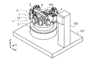
- FIG. 4 is an external perspective view showing a configuration example of the coil terminal wire cutting device according to the first embodiment of the present invention.
- the coil terminal wire cutting device 100 includes a cutting unit 2 that cuts the terminal wire wound around the pin 7, and a stator holding unit 3 that holds the stator 1 when cutting the terminal wire.
- the stator holder 3 is supported by the pedestal 101.
- the stator holder 3 is provided with a mounting table 3a on which the stator 1 in the state shown in FIG. 3 is placed.
- the cutting section 2 is supported by the pedestal 101 via a column 102 provided on the pedestal 101.
- a stator fixing portion that fixes the position of the stator 1 placed on the mounting table 3a so as not to be displaced may be provided on the mounting table 3a.
- the cutting unit 2 cuts the terminal wire of the coil 13 wound around the pin 7 while gripping the terminal wire.
- the cutting section 2 has a pair of grip pieces 46 composed of a movable piece 4 and a fixed piece 6 for gripping the terminal wire, and a drive section 103 provided on the support column 102.
- the fixed piece 6 is attached to the column 102.
- the moving piece 4 is attached to the drive unit 103.
- the driving unit 103 horizontally moves the moving piece 4 in a fixed direction (X-axis arrow direction).
- the drive unit 103 is provided with, for example, an air cylinder (not shown), and the air cylinder is connected to an air compressor via an air pipe.
- the drive unit 103 can move the moving piece 4 in the X-axis arrow direction shown in FIG. 4 and the moving piece 4 in the opposite direction to the X-axis arrow direction by the air pressure supplied from the air compressor.
- FIG. 5 is an enlarged view showing a configuration example of a main part of the cutting section shown in FIG.
- FIG. 5 is a view of the main part of the cutting part 2 seen from above the coil terminal wire cutting device 100 shown in FIG. 4 in the direction opposite to the Z-axis arrow.
- the description will be made focusing on the configurations of the moving piece 4 and the fixed piece 6.
- the moving piece 4 has a moving base 4a to which the cutting edge 5 is fixed, and a rectangular moving protrusion 4b extending in the moving direction (X-axis arrow direction) from the moving base 4a.
- the tip 5b of the cutting blade 5 projects in the moving direction of the moving piece 4 more than the moving base 4a.
- a space 4c is formed between the side surface 4b1 of the moving protrusion 4b in the direction of the pin 7 side (the direction opposite to the Y-axis arrow) and the surface of the cutting blade 5 in the direction of the moving protrusion 4b. ..
- the cutting blade 5 is arranged so as to separate the moving protrusion 4b and the space 4c.
- the fixed piece 6 has a fixed base portion 6a arranged to face the movable piece 4 in the moving direction of the movable piece 4, and a rectangular fixed protruding portion 6b extending in the direction of the space 4c.
- the fixed protruding portion 6b is arranged at a position facing the pin 7.
- a side surface 4b2 that is a surface of the moving protrusion 4b in the direction of the fixed piece 6 (direction of the X-axis arrow) and a surface of the fixed base 6a in the direction of the movable piece 4 (direction opposite to the arrow of the X-axis).
- the side surface 6a1 which is The side surface 4a1 that is the surface of the movable base portion 4a in the direction of the fixed piece 6 and the side surface 6b3 that is the surface of the fixed protrusion 6b in the direction of the movable piece 4 are arranged facing each other.
- the surface in the X-axis arrow direction is a side surface 7b.
- the side surface 4b2 of the movable protrusion 4b and the tip 5b of the cutting edge 5 are on the virtual line X1 parallel to the Y-axis direction
- the side surface 6b3 of the fixed protrusion 6b and the side surface 7a of the pin 7 are provided. And are on an imaginary line X2 parallel to the Y-axis direction.
- the surface in the direction opposite to the pin 7 (the direction of the Y-axis arrow) is defined as the side surface 6b1.
- the surface in the pin 7 side direction is defined as a receiving surface 6b2 that is a side surface that receives the cutting blade 5.
- the shape in which the moving base portion 4a and the moving protrusion portion 4b are combined is similar to the shape when the L-shape is rotated 90 degrees clockwise in a plan view.
- the shape in which the fixed base portion 6a and the fixed protruding portion 6b are combined is similar to the shape when the L-shape is rotated 90 degrees counterclockwise in plan view.
- FIG. 6 is an external perspective view showing a state where the stator shown in FIG. 3 is installed in the coil terminal wire cutting device shown in FIG.
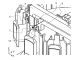
- FIG. 7 is an enlarged view showing a main part of the coil terminal wire cutting device shown in FIG.
- the stator 1 in the state shown in FIG. 3 is attached to the stator holding portion 3. 6 and 7, the coils 13 formed on each tooth 10 of the stator 1 are not shown in the drawings.
- the wire extending from the coil 13 shown in FIG. 2 is fixed to the fixed terminal 14, and the terminal wire 8 of the coil 13 further extending from the fixed terminal 14 is wound around the pin 7.
- a terminal wire 8 extends from the pin 7 so as to pass between the fixed piece 6 and the movable piece 4 of the cutting portion 2.
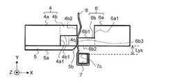
- FIG. 8 is an enlarged view showing a state before the coil terminal wire cutting device shown in FIG. 7 cuts the terminal wire.
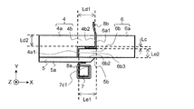
- FIG. 9 is an enlarged view showing a state after the coil terminal wire cutting device shown in FIG. 7 cuts the terminal wire.
- FIG. 8 shows an example of a state in which the terminal wire 8 is arranged between the moving piece 4 and the fixed piece 6 as described with reference to FIG. 7.
- the stator holding portion 3 shown in FIG. 6 holds the stator 1 so that the pin 7 is arranged close to and opposite one end of the fixed piece 6.
- the pin 7 is arranged so as to face the fixed protrusion 6b with a certain distance Lys therebetween.
- the distance Lys is, for example, a distance equal to or larger than a value obtained by adding the thickness of the cutting edge 5 and the diameter of the terminal wire 8.
- the tip 5b of the cutting blade 5 is in contact with the terminal wire 8, but is in a state before the cutting blade 5 cuts the terminal wire 8.
- the side 4b3 of the side surface 4b2 of the moving protrusion 4b and the side 6b4 of the side surface 6b3 of the fixed protrusion 6b are in contact with the terminal wire 8.
- the terminal wire 8 moves the side 4b3 of the moving protrusion 4b and the fixed protrusion 6b. It is strongly gripped by the side 6b4 and is cut by the cutting edge 5. Further, when the moving piece 4 moves in the moving direction, as shown in FIG. 9, the terminal wire 8b separated from the pin 7 side is pressed against the side surface 6a1 of the fixed base 6a by the side surface 4b1 of the moving protrusion 4b and the side 4b3. To be The terminal wire 8b is temporarily held by the side surface 4b2 of the moving piece 4 and the side surface 6a1 of the fixed piece 6.
- the fixed protrusion 6b enters the space 4c of the moving piece 4.
- the side surface 6b1 of the fixed protrusion 6b and the side surface 4b1 of the moving protrusion 4b are opposed to each other, but the terminal wire 8b includes the side surface 6b1 and the side surface 6b1. Not retained by 4b1.
- the distance Lc which is the difference between the length of the side surface 4a1 in the Y-axis arrow direction and the length of the side surface 6b3 in the Y-axis arrow direction, is larger than the diameter of the terminal wire 8. That is, the distance Lc between the side surface 6b1 of the fixed protrusion 6b and the side surface 4b1 of the movable protrusion 4b is larger than the diameter of the terminal wire 8 in the state where the fixed protrusion 6b is housed in the space 4c. ..
- the side surface 6a1 of the fixed base portion 6a and the side surface 4b2 of the moving protrusion 4b are at positions facing each other, and the separated terminal wire 8b is temporarily held by the side surface 6a1 and the side surface 4b2.
- the separated terminal wire 8b is not held between the side surface 4a1 of the movable base 4a and the side surface 6b3 of the fixed protrusion 6b.
- a value obtained by adding the length Le1 of the moving protrusion 4b in the X-axis arrow direction and the length Ld1 of the fixed protrusion 6b in the X-axis arrow direction is defined as the length Lde1.
- a value obtained by adding the length Le2 of the moving protrusion 4b in the Y-axis arrow direction and the length Ld2 of the fixed protrusion 6b in the Y-axis arrow direction is defined as the length Lde2.
- a part of the separated terminal wire 8b remains between the side surface 4b1 and the side surface 6b1 shown in FIG. 8, but remains between the side surface 4a1 and the side surface 6b3. It gets harder.
- the receiving surface 6b2 of the fixed protrusion 6b and one side surface of the pin 7 are arranged in close proximity to each other.
- the receiving surface 6b2 of the fixed protrusion 6b and the side surface 7c of the pin 7 are arranged with a distance Lys.
- the tip 5b of the cutting blade 5 that slides along the receiving surface 6b2 has a pin shape in plan view. 7 reaches the position beyond the side surface position.
- the tip 5b of the cutting edge 5 reaches a position beyond the side 7c1 of the side surface 7c of the pin 7. Therefore, the terminal wire 8a cut by the cutting blade 5 is pushed to the pin 7 side by the holding surface 5a, which is the surface of the cutting blade 5 on the pin 7 side, and is wound around the pin 7.
- the distance Lys is equal to or more than the value obtained by adding the thickness of the cutting edge 5 and the diameter of the terminal wire 8, but the distance Lys is not limited to this case.
- the distance Lys may be equal to or more than a value obtained by adding the thickness of the cutting edge 5 and the diameter of the terminal wire 8 and may be equal to or more than the length of the side surface 7c shown in FIG. 8 in the X-axis arrow direction. This is because the length of the terminal wire 8a pressed by the pressing surface 5a of the cutting blade 5 is sufficient if the side surface 7c of the pin 7 has the length in the X-axis arrow direction as the length around which the pin 7 is wound.
- the coil terminal wire cutting device 100 includes a stator holding portion 3 that holds a stator 1 including a pin 7 around which a terminal wire 8 that is an end portion of a coil 13 is wound, and a winding wire around the pin 7.
- the cutting unit 2 includes a pair of grip pieces 46 that grip the terminal wire 8 when the terminal wire 8 is cut.
- the cutting unit 2 includes a fixed piece 6 that is one of the pair of grip pieces 46 and a movable piece 4 that is the other grip piece of the pair of grip pieces and that includes the cutting blade 5.
- the moving piece 4 moves to a position where the tip 5b of the cutting blade 5 exceeds the position of the pin 7 around which the terminal wire 8 is wound while pushing the terminal wire 8 toward the fixed piece 6.
- the moving piece 4 and the fixed piece 6 hold the terminal wire 8, and the cutting blade 5 cuts the held terminal wire 8.
- the cutting blade 5 moves to a position beyond the position of the pin 7, the cutting blade 5 pushes the terminal wire 8a after cutting in the moving direction of the moving piece 4, and the terminal wire 8a winds around the pin 7. Since the terminal wire 8a after cutting is wound around the pin 7, the terminal wire 8a is unlikely to come off the pin 7. Therefore, it is possible to prevent the terminal wire 8a after cutting from coming off from the pin 7. As a result, the reliability of not only the electric motor 200 but also the product in which the electric motor 200 is mounted is improved.
- the stator holding portion 3 may hold the stator 1 so that the pins 7 are arranged to face the fixed piece 6 with a certain distance.
- the terminal wire 8 a can be reliably wound around the pin 7.
- the fixed protrusion 6b is arranged to face the pin 7, and the distance Lys between the fixed protrusion 6b and the pin 7 may be equal to or greater than the value obtained by adding the thickness of the cutting edge 5 and the diameter of the terminal wire 8.
- the distance Lys between the fixed protrusion 6b and the pin 7 is a value obtained by adding at least the thickness of the cutting edge 5 and the diameter of the terminal wire 8, when the tip 5b of the cutting edge 5 moves beyond the position of the pin 7,
- the pressing surface 5a of the cutting blade 5 extends the terminal wire 8a along the side surface 7c of the pin 7. As a result, the terminal wire 8a is less likely to come off the side surface 7c of the pin 7.
- the terminal wire when the terminal wire is cut, the convex portion of the moving piece and the concave portion of the fixed piece engage with each other with the terminal wire sandwiched between them. Therefore, the terminal wire is bent at three places, and the terminal wire becomes a concave portion. I will cut in. Therefore, even if the moving piece returns to the position before the movement, the terminal wire may not drop from the recess of the fixed piece by its own weight. In this case, the worker had to remove the terminal wire after cutting from the fixing piece.
- the tip 5b of the cutting blade 5 is arranged with the moving projection 4b and the space 4c separated from each other, after the cutting blade 5 cuts the terminal wire 8, the fixed projection The part 6b is housed in the space 4c, and the moving piece 4 and the fixed piece 6 are combined.
- the terminal wire 8b after cutting on the side opposite to the coil 13 moves in the direction of the fixed base 6a with the movement of the moving protrusion 4b.
- the terminal wire 8b is gripped by the side surface 4b2 of the movable protrusion 4b and the side surface 6a1 of the fixed base portion 6a, but is not gripped between the side surface 4b1 and the side surface 6b1 in the vertical direction (Y-axis arrow direction).
- the moving piece 4 and the fixed piece 6 are not configured to bite into the terminal wire 8, they do not grip the bent portion of the terminal wire 8 by applying force from both sides. Therefore, it is possible to prevent the terminal wire 8b on the side separated from the coil 13 from sticking to the fixing piece 6 and not being separated by its own weight, and it is possible to prevent the terminal wire 8b from being difficult to remove.
- the cutting edge 5 follows the receiving surface 6b2 which is a side surface facing the pin 7 of the fixed protruding portion 6b. It is configured to move.
- the terminal wire 8 can be cut without a cutting edge on the fixed piece side, the manufacturing cost of the coil terminal wire cutting device can be reduced.
- the convex portion is not provided on the moving piece 4, and the concave portion that meshes with the convex portion is on the fixing piece 6. It is not provided and the number of cutting blades 5 is one. Therefore, the sizes of the movable piece 4 and the fixed piece 6 in the cutting portion 2 can be reduced as compared with the conventional size. As a result, the discarded portion of the terminal line 8b after cutting can be reduced.
- the distance Lc between the side surface 6b1 of the fixed protrusion 6b and the side surface 4b1 of the movable protrusion 4b is the terminal line 8 with the fixed protrusion 6b housed in the space 4c.
- the structure may be larger than the diameter.
- stator 1 stator, 2 cutting part, 3 stator holding part, 3a mounting table, 4 moving piece, 4a moving base, 4a1 side face, 4b moving protrusion, 4b1, 4b2 side face, 4b3 side, 4c space part, 5 cutting edge, 5a presser foot Face, 5b tip, 6 fixing piece, 6a fixing base, 6a1 side, 6b fixing protrusion, 6b1 side, 6b2 receiving surface, 6b3 side, 6b4 side, 7 pin, 7a-7c side, 7c1 side, 8, 8a, 8b Terminal wire, 10 teeth, 11 core, 12 insulator, 13 coil, 14 fixed terminal, 20 mold stator, 21 circuit board, 22 mold resin, 23 lead wire, 24 lead wire port, 30 rotor, 31 rotating shaft, 32 rotating body , 33 output side bearing, 34 counter output side bearing, 40 rotor magnet, 46 pair of gripping pieces, 50 magnetic sensor, 60 bracket, 61 press-fitting section, 100 coil terminal wire cutting device, 101 pedestal, 102 support, 103 drive section,
Landscapes
- Engineering & Computer Science (AREA)
- Manufacturing & Machinery (AREA)
- Power Engineering (AREA)
- Manufacture Of Motors, Generators (AREA)
Abstract
コイル端末線切断装置は、コイルが巻かれるインシュレータと、インシュレータの上部に設けられ、インシュレータに巻かれたコイルの端部となる端末線が巻かれたピンとを備えたステータを保持するステータ保持部と、ピンに巻かれた端末線の切断時に端末線を把持する一対の把持片を備えた切断部とを有し、切断部は、一対の把持片のうち、一方の把持片である固定片と、一対の把持片のうち、他方の把持片であって、切刃を備え、端末線を固定片の方向に押しながら切刃の先端が端末線の巻かれたピンの位置を超える位置まで移動する移動片とを有するものである。
Description
本発明は、電動機のステータにコイルを巻く工程において、コイルの端部である端末線を切断するコイル端末線切断装置に関する。
従来、巻線機におけるコイル端末線切断装置として、端末線を保持する移動片および固定片の各片に、コイルから延びる端末線を切断する切刃が設けられた装置が知られている(例えば、特許文献1参照)。特許文献1に開示されたコイル端末線切断装置では、切断前の端末線を保持する構成として、移動片の中央に凸部が設けられ、凸部と噛み合う凹部が固定片に設けられている。
特許文献1に開示されたコイル端末線切断装置は、端末線を保持する移動片および固定片の各片に切刃が設けられており、切刃が端末線を切断すると、切断後の端末線がコイル側に向かって伸びた状態となる。この場合、例えば、コイルが搭載される電動機の製造過程において、コイルから延びる端末線を巻き付けておくピンがステータに設けられていたとしても、作業者が、切断後の端末線に触れてしまうと、端末線がピンから容易にほどけてしまう。端末線がピンから外れることを防げない。端末線がピンから外れることが頻繁に起こると、コイルが搭載される電動機の品質が安定しなくなり、信頼性が低下する。
本発明は、上記のような課題を解決するためになされたもので、コイルの端末線を切断した際に、ピンに巻かれたコイル端末線がピンから外れることを防止するコイル端末線切断装置を提供するものである。
本発明に係るコイル端末線切断装置は、コイルが巻かれるインシュレータと、前記インシュレータの上部に設けられ、前記インシュレータに巻かれたコイルの端部となる端末線が巻かれたピンとを備えたステータを保持するステータ保持部と、前記ピンに巻かれた前記端末線の切断時に前記端末線を把持する一対の把持片を備えた切断部と、を有し、前記切断部は、前記一対の把持片のうち、一方の把持片である固定片と、前記一対の把持片のうち、他方の把持片であって、切刃を備え、前記端末線を前記固定片の方向に押しながら前記切刃の先端が前記端末線の巻かれた前記ピンの位置を超える位置まで移動する移動片と、を有するものである。
本発明によれば、移動片が固定片の方向に移動すると、移動片と固定片とが端末線を把持し、把持された端末線を切刃が切断する。切刃がピンの位置を超える位置まで移動することで、切刃が、切断後の端末線を移動片の移動方向に押し、端末線がピンに巻き付く。切断後の端末線がピンに巻き付く状態となるため、端末線がピンから外れにくくなり、切断後の端末線がピンから外れることを防止できる。
実施の形態1.
本実施の形態1は、電動機の製造過程において、ステータに巻かれるコイルを切断するコイル端末切断装置に関するものである。本実施の形態1のコイル端末切断装置の構成を説明する前に、電動機の構成を説明する。
本実施の形態1は、電動機の製造過程において、ステータに巻かれるコイルを切断するコイル端末切断装置に関するものである。本実施の形態1のコイル端末切断装置の構成を説明する前に、電動機の構成を説明する。
図1は、本発明の実施の形態1に係るコイル端末線切断装置を用いて製造される電動機の一構成例を示す外観図である。ここでは、電動機がブラシレスDCモータの場合で説明する。図1は、電動機の構成をわかり易く説明するために、電動機の一部を断面構造で示している。図1は、ラジアルギャップ形ブラシレスDCモータを示しているが、電動機はラジアルギャップ形に限らない。
図1に示すように、電動機200は、回転軸31が挿入されたロータ30と、ロータ30の外周に設けられたステータ1と、ロータ30の駆動を制御する回路が搭載された回路基板21とを有する。ステータ1および回路基板21がモールド樹脂22で一体に成型され、モールドステータ20が構成される。モールドステータ20の凹部にはロータ30が収納されている。
回転軸31の一端には、回転する回転軸31を支持する出力側軸受33が設けられている。回転軸31の他端には、回転する回転軸31を支持する反出力側軸受34が設けられている。反出力側軸受34は、導電性のブラケット60で覆われている。反出力側軸受34の外輪がブラケット60の内側に嵌め込まれている。ブラケット60がモールドステータ20の凹部の開口部を塞ぐように、ブラケット60の圧入部61がモールドステータ20の内周部に嵌め込まれている。
ステータ1は、回転軸31を中心に放射状に配置された複数のコア11と、複数のコア11に対応して設けられた複数のインシュレータ12とを有する。各コア11は、複数の電磁鋼板が積層された構成である。各コア11には、磁束を発生させるコイル13が巻きつけられている。コイル13は、銅およびアルミなどの導電性線材で構成される。インシュレータ12は、コア11とコイル13とを絶縁する役目を果たす。ロータ30は、回転軸31と、回転軸31に回転体32を介して固定されたロータマグネット40とを有する。ロータマグネット40は、円柱状の永久磁石で構成される。ロータマグネット40は、モールドステータ20の内側に配置された複数のコア11と対向して配置されている。
回路基板21は、出力側軸受33とステータ1との間に配置されている。回路基板21には、ロータ30の磁極位置を検出する磁気センサ50が設けられている。回路基板21にはリード線23が接続され、リード線23は、リード線口24を介して、電動機200が搭載される装置のコントローラ(不図示)と接続されている。電動機200が搭載される装置は、例えば、空気調和機である。
図2は、図1に示したステータの一構成例を示す外観斜視図である。図2は、ステータ1が図1に示した電動機200に搭載される場合の一例を示す図である。図2では、仮想的に配置される回転軸31を破線で示している。
図2に示すように、ステータ1は複数のティース10を有する。ステータ1は、複数のティース10が平面視で環状に配置された構成である。各ティース10は、環状のステータ1の外周側に位置するコア11と、コア11から環状のステータ1の内周側に突出するインシュレータ12と、コイル13とを有する。コイル13は、インシュレータ12にワイヤが巻き付けられた構成である。インシュレータ12の上部には、固定端子14およびピン7が設けられている。固定端子14は、コイル13から延びるワイヤを固定し、ステータ1の上部に設けられる回路基板21に電気的に接続するために用いられる。ピン7には、固定端子14に固定されたワイヤから延びるワイヤの端部である端末線が巻き付けられる。図1に示した電動機200にステータ1が搭載された場合、図2に示すように、複数のティース10は、コイル13の巻かれたインシュレータ12が破線で示す回転軸31に向くように配置される。
図3は、図2に示したステータについて、各インシュレータが外側を向くように配置された状態を示す外観斜視図である。図3では、図2に示したコイル13を図に示すことを省略している。電動機200の製造過程において、ティース10にコイル13を形成する際、図3に示すように、各インシュレータ12が外側を向くように、ステータ1が配置される。
次に、本実施の形態1のコイル端末線切断装置の構成を説明する。図4は、本発明の実施の形態1に係るコイル端末線切断装置の一構成例を示す外観斜視図である。図4に示すように、コイル端末線切断装置100は、ピン7に巻き付けられた端末線を切断する切断部2と、端末線の切断時にステータ1を保持するステータ保持部3とを有する。ステータ保持部3は台座101に支持されている。ステータ保持部3には、図3に示した状態のステータ1が置かれる載置台3aが設けられている。切断部2は、台座101の上に設けられた支柱102を介して、台座101に支持されている。図4に示していないが、載置台3aに置かれるステータ1の位置がずれないように固定するステータ固定部が、載置台3aに設けられていてもよい。
切断部2は、インシュレータ12にコイル13が形成された後、ピン7に巻き付けられた、コイル13の端末線を把持しながら端末線を切断する。切断部2は、端末線を把持する移動片4および固定片6からなる一対の把持片46と、支柱102に設けられた駆動部103とを有する。固定片6は支柱102に取り付けられている。移動片4は駆動部103に取り付けられている。駆動部103は水平に一定の方向(X軸矢印方向)に移動片4を移動させる。駆動部103は、例えば、図に示さないエアーシリンダが設けられ、エアーシリンダがエアーパイプを介してエアーコンプレッサと接続されている。駆動部103は、エアーコンプレッサから供給される空気圧によって、図4に示すX軸矢印方向に移動片4を移動させ、およびX軸矢印方向と反対方向に移動片4を移動させることができる。
図4に示した切断部2の要部の構成を説明する。図5は、図4に示した切断部の要部の構成例を示す拡大図である。図5は、図4に示したコイル端末線切断装置100の上方からZ軸矢印の反対方向に切断部2の要部を見たときの図である。ここでは、移動片4および固定片6の構成に注目して説明する。
移動片4は、切刃5が固定された移動基部4aと、移動基部4aよりも移動方向(X軸矢印方向)に延びる矩形状の移動突出部4bとを有する。切刃5は、図5に示すように、切刃5の先端5bが移動基部4aよりも移動片4の移動方向に突出している。移動突出部4bのピン7側方向(Y軸矢印と反対方向)の面である側面4b1と、切刃5の移動突出部4b側方向の面との間に、空間部4cが形成されている。切刃5は、移動突出部4bと空間部4cを隔てて配置されている。固定片6は、移動片4の移動方向に、移動片4と対向して配置された固定基部6aと、空間部4cの方向に延びる矩形状の固定突出部6bとを有する。固定突出部6bはピン7と対向する位置に配置されている。
図5に示すように、移動突出部4bの固定片6側方向(X軸矢印方向)の面である側面4b2と、固定基部6aの移動片4側方向(X軸矢印と反対方向)の面である側面6a1とが対向して配置されている。移動基部4aの固定片6側方向の面である側面4a1と、固定突出部6bの移動片4側方向の面である側面6b3とが対向して配置されている。ピン7において、図5に示すX軸矢印と反対方向の面を側面7aとし、X軸矢印方向の面を側面7bとする。図5に示す構成例では、移動突出部4bの側面4b2と切刃5の先端5bとがY軸方向に平行な仮想線X1上にあり、固定突出部6bの側面6b3とピン7の側面7aとがY軸方向に平行な仮想線X2上にある。固定突出部6bにおいて、ピン7とは反対方向(Y軸矢印方向)の面を側面6b1とする。また、固定突出部6bにおいて、ピン7側方向(Y軸矢印と反対方向)の面を、切刃5を受ける側面である受面6b2とする。
図5に示す移動片4を参照すると、移動基部4aと移動突出部4bとが組み合わされた形状は、平面視でL字が時計回りに90度回転したときの形状に近似している。また、図5に示す固定片6を参照すると、固定基部6aと固定突出部6bとが組み合わされた形状は、平面視でL字が反時計回りに90度回転したときの形状に近似している。後述するが、移動片4と固定片6との間に端末線が配置された状態で、移動片4が駆動部103から供給される動力によって、図5に示す位置から固定片6の方向(X軸矢印方向)に移動する。移動片4が移動方向(X軸矢印方向)に移動すると、2つのL字形状が組み合わされる。その際、固定突出部6bが空間部4cに収納され、切刃5によってコイル13側から切り離された端末線が移動片4および固定片6に把持される。
次に、本実施の形態1のコイル端末線切断装置100の動作を説明する。図6は、図4に示したコイル端末線切断装置に図3に示したステータが設置された状態を示す外観斜視図である。図7は、図6に示したコイル端末線切断装置の要部を示す拡大図である。
図6に示すように、ステータ保持部3には、図3に示した状態のステータ1が取りつけられる。図6および図7では、ステータ1の各ティース10に形成されたコイル13を、図に示すことを省略している。固定端子14には、図2に示したコイル13から延びるワイヤが固定され、ピン7には、固定端子14からさらに延びるコイル13の端末線8が巻き付けられる。切断部2の固定片6と移動片4との間を通るように、ピン7から端末線8が伸びている。
図8は、図7に示したコイル端末線切断装置が端末線を切断する前の状態を示す拡大図である。図9は、図7に示したコイル端末線切断装置が端末線を切断した後の状態を示す拡大図である。図8は、図7を参照して説明したように、移動片4と固定片6との間に端末線8が配置された状態の一例を示す。
図6に示したステータ保持部3は、ピン7が固定片6の一端部に近接して対向して配置されるようにステータ1を保持する。図8に示す配置例では、ピン7は、固定突出部6bと一定の距離Lysを空けて対向して配置されている。距離Lysは、例えば、切刃5の厚みと端末線8の直径とを加算した値以上の距離である。図8に示す配置例では、切刃5の先端5bが端末線8と接触しているが、切刃5が端末線8を切断する前の状態である。また、移動突出部4bの側面4b2の辺4b3と固定突出部6bの側面6b3の辺6b4とが端末線8に接触している。
図8に示した状態から、移動片4が駆動部103から供給される動力によって移動方向(X軸矢印方向)に移動すると、端末線8は、移動突出部4bの辺4b3と固定突出部6bの辺6b4とで強く把持され、切刃5によって切断される。さらに、移動片4が移動方向に移動すると、図9に示すように、ピン7側から切り離された端末線8bは、移動突出部4bの側面4b1および辺4b3によって固定基部6aの側面6a1に押しつけられる。端末線8bは、移動片4の側面4b2および固定片6の側面6a1によって、一時的に保持される。
また、図8に示した状態から、移動片4が移動方向に移動すると、移動片4のL字状の先端側矩形と固定片6のL字状の先端側矩形とが組み合わされ、図9に示すように、固定突出部6bが移動片4の空間部4cに侵入する。固定突出部6bが移動片4の空間部4cに侵入した状態において、固定突出部6bの側面6b1と移動突出部4bの側面4b1とが対向しているが、端末線8bは、側面6b1および側面4b1によって保持されない。これは、側面4a1のY軸矢印方向の長さと側面6b3のY軸矢印方向の長さとの差である距離Lcが端末線8の直径よりも大きいからである。つまり、固定突出部6bが空間部4cに収納された状態で、固定突出部6bの側面6b1と移動突出部4bの側面4b1との間の距離Lcが端末線8の直径よりも大きいからである。
上述したように、固定基部6aの側面6a1および移動突出部4bの側面4b2は互いに対向する位置にあり、切り離された端末線8bは、側面6a1および側面4b2によって一時的に保持される。一方、移動基部4aの側面4a1と固定突出部6bの側面6b3との間では、切り離された端末線8bは保持されない。その理由を説明する。移動突出部4bのX軸矢印方向の長さLe1および固定突出部6bのX軸矢印方向の長さLd1を加算した値を長さLde1とする。移動突出部4bのY軸矢印方向の長さLe2および固定突出部6bのY軸矢印方向の長さLd2を加算した値を長さLde2とする。本実施の形態1では、Lde1>Lde2の関係になっている。この場合、Lde1=Lde2の場合に比べて、切り離された端末線8bの一部は、図8に示した側面4b1と側面6b1との間に残るが、側面4a1と側面6b3との間に残りにくくなる。
また、固定突出部6bの受面6b2とピン7の一側面とが、互いに対向して、近接して配置されている。図8に示す配置例では、固定突出部6bの受面6b2とピン7の側面7cとが距離Lysを空けて配置されている。図8に示した状態から移動片4が移動方向(X軸矢印方向)に移動すると、図9に示すように、切刃5は、端末線8を切断した後、固定突出部6bの受面6b2に沿ってスライドする。移動片4が移動して、図9に示すように、固定突出部6bが空間部4cに収納されると、受面6b2に沿ってスライドする切刃5の先端5bは、平面視において、ピン7の側面の位置を超える位置に到達する。図9の例では、切刃5の先端5bは、ピン7の側面7cの辺7c1を超える位置に到達している。そのため、切刃5によって切断された端末線8aは、切刃5のピン7側の面である押え面5aによってピン7側に押され、ピン7に巻き付く。
なお、距離Lysが切刃5の厚みと端末線8の直径とを加算した値以上の場合で説明したが、距離Lysはこの場合に限らない。距離Lysは、切刃5の厚みと端末線8の直径とを加算した値以上であり、かつ図8に示した側面7cのX軸矢印方向の長さ以上であってもよい。端末線8aについて、切刃5の押え面5aによって押さえられる長さは、ピン7に巻き付く長さとして、ピン7の側面7cのX軸矢印方向の長さがあれば十分だからである。
本実施の形態1のコイル端末線切断装置100は、コイル13の端部となる端末線8が巻かれたピン7を備えたステータ1を保持するステータ保持部3と、ピン7に巻かれた端末線8の切断時に端末線8を把持する一対の把持片46を備えた切断部2とを有する。切断部2は、一対の把持片46のうち、一方の把持片である固定片6と、一対の把持片のうち、他方の把持片であって、切刃5を備えた移動片4とを有する。移動片4は、端末線8を固定片6の方向に押しながら切刃5の先端5bが端末線8の巻かれたピン7の位置を超える位置まで移動するものである。
本実施の形態1によれば、移動片4が固定片6の方向に移動すると、移動片4と固定片6とが端末線8を把持し、把持された端末線8を切刃5が切断する。切刃5がピン7の位置を超える位置まで移動することで、切刃5が、切断後の端末線8aを移動片4の移動方向に押し、端末線8aがピン7に巻き付く。切断後の端末線8aがピン7に巻き付く状態となるため、端末線8aがピン7から外れにくくなる。そのため、切断後の端末線8aがピン7から外れることを防止できる。その結果、電動機200だけでなく、電動機200が搭載される製品の信頼性が向上する。
また、本実施の形態1において、ステータ保持部3は、固定片6に対して一定の距離を空けてピン7が対向して配置されるように、ステータ1を保持してもよい。ピン7が固定片6の一端部に近接して対向して配置されるようにすることで、端末線8aをピン7に確実に巻きつけることができる。固定突出部6bがピン7と対向して配置され、固定突出部6bとピン7との距離Lysは切刃5の厚みと端末線8の直径とを加算した値以上であればよい。固定突出部6bとピン7との距離Lysが少なくとも切刃5の厚みと端末線8の直径とを加算した値であれば、切刃5の先端5bがピン7の位置を超えて移動すると、切刃5の押え面5aが端末線8aをピン7の側面7cに沿って伸ばす。その結果、端末線8aはピン7の側面7cから外れにくくなる。
従来のコイル端末線切断装置では、端末線を切断する際、移動片の凸部と固定片の凹部とが端末線を挟んで噛み合う構成なので、端末線が3箇所で折れ曲がり、端末線が凹部に食い込んでしまう。そのため、移動片が移動前の位置に戻っても、端末線が固定片の凹部から自重で落ちない場合がある。この場合、作業者が切断後の端末線を固定片から除去しなければならなかった。
これに対して、本実施の形態1では、切刃5の先端5bが移動突出部4bと空間部4cを隔てて配置されているため、切刃5が端末線8を切断した後に、固定突出部6bが空間部4cに収納され、移動片4と固定片6とが組み合わされる。その際、コイル13とは反対側の切断後の端末線8bは、移動突出部4bの移動に伴って固定基部6aの方向に移動する。そして、端末線8bは、移動突出部4bの側面4b2と固定基部6aの側面6a1とで把持されるが、垂直方向(Y軸矢印方向)の側面4b1と側面6b1との間では把持されない。このように、移動片4および固定片6は、端末線8に食い込む構成ではないため、端末線8の折れ曲がった部分に両側から力をかけて把持するものではない。そのため、コイル13から切り離された側の端末線8bが固定片6に張り付いて自重で離れなくなることが抑制され、端末線8bが除去しづらい状態になることを防止できる。
また、本実施の形態1のコイル端末線切断装置100は、移動片4が移動方向に移動する際、切刃5は、固定突出部6bのピン7と対向する側面である受面6b2に沿って移動する構成である。この場合、固定片側に切刃が無くても端末線8を切断することができるため、コイル端末線切断装置の製造コストを削減することができる。
また、従来のコイル端末線切断装置と比較すると、本実施の形態1のコイル端末線切断装置100は、凸部が移動片4に設けられておらず、凸部と噛み合う凹部が固定片6に設けられておらず、切刃5の枚数が1枚である。そのため、切断部2における移動片4および固定片6のサイズを従来よりも縮小することができる。その結果、切断した後の端末線8bの廃棄部分を少なくすることができる。
さらに、本実施の形態1において、固定突出部6bが空間部4cに収納された状態で、固定突出部6bの側面6b1と移動突出部4bの側面4b1との間の距離Lcが端末線8の直径よりも大きい構成であってもよい。この場合、コイル13から切り離された端末線8bは移動突出部4bおよび固定基部6aで保持されているので、移動片4が固定片6から離れるだけで、端末線8bが自重で落下する。そのため、端末線8bを落としやすくすることができる。
1 ステータ、2 切断部、3 ステータ保持部、3a 載置台、4 移動片、4a 移動基部、4a1 側面、4b 移動突出部、4b1、4b2 側面、4b3 辺、4c 空間部、5 切刃、5a 押え面、5b 先端、6 固定片、6a 固定基部、6a1 側面、6b 固定突出部、6b1 側面、6b2 受面、6b3 側面、6b4 辺、7 ピン、7a~7c 側面、7c1 辺、8、8a、8b 端末線、10 ティース、11 コア、12 インシュレータ、13 コイル、14 固定端子、20 モールドステータ、21 回路基板、22 モールド樹脂、23 リード線、24 リード線口、30 ロータ、31 回転軸、32 回転体、33 出力側軸受、34 反出力側軸受、40 ロータマグネット、46 一対の把持片、50 磁気センサ、60 ブラケット、61 圧入部、100 コイル端末線切断装置、101 台座、102 支柱、103 駆動部、200 電動機、X1、X2 仮想線。
Claims (6)
- コイルが巻かれるインシュレータと、前記インシュレータの上部に設けられ、前記インシュレータに巻かれたコイルの端部となる端末線が巻かれたピンとを備えたステータを保持するステータ保持部と、
前記ピンに巻かれた前記端末線の切断時に前記端末線を把持する一対の把持片を備えた切断部と、を有し、
前記切断部は、
前記一対の把持片のうち、一方の把持片である固定片と、
前記一対の把持片のうち、他方の把持片であって、切刃を備え、前記端末線を前記固定片の方向に押しながら前記切刃の先端が前記端末線の巻かれた前記ピンの位置を超える位置まで移動する移動片と、
を有するコイル端末線切断装置。 - 前記ステータ保持部は、前記固定片に対して一定の距離を空けて前記ピンが対向して配置されるように、前記ステータを保持する、請求項1に記載のコイル端末線切断装置。
- 前記移動片は、
前記切刃が固定される移動基部と、
前記移動基部よりも前記移動片の移動方向に延びる移動突出部と、を有し、
前記切刃は、前記切刃の先端が前記移動基部よりも前記移動方向に突出して前記移動突出部と空間部を隔てて配置されるように、前記移動基部に固定され、
前記固定片は、
前記移動方向に前記移動片と対向して配置された固定基部と、
前記移動片が移動すると前記空間部に収納される固定突出部と、を有する、請求項1または2に記載のコイル端末線切断装置。 - 前記切刃は、前記移動片が移動するとき、前記固定突出部の前記ピンと対向する面に沿って移動する、請求項3に記載のコイル端末線切断装置。
- 前記固定突出部が前記空間部に収納された状態において、前記固定突出部の側面と前記移動突出部の側面との間の距離が前記端末線の直径よりも大きい、請求項3または4に記載のコイル端末線切断装置。
- 前記ステータ保持部は、
前記切刃の厚みと前記端末線の直径とを加算した値以上の距離を空けて、前記固定突出部に対して前記ピンが対向して配置されるように、前記ステータを保持する、請求項3~5のいずれか1項に記載のコイル端末線切断装置。
Priority Applications (2)
| Application Number | Priority Date | Filing Date | Title |
|---|---|---|---|
| PCT/JP2019/006992 WO2020174519A1 (ja) | 2019-02-25 | 2019-02-25 | コイル端末線切断装置 |
| JP2021501381A JPWO2020174519A1 (ja) | 2019-02-25 | 2019-02-25 | コイル端末線切断装置 |
Applications Claiming Priority (1)
| Application Number | Priority Date | Filing Date | Title |
|---|---|---|---|
| PCT/JP2019/006992 WO2020174519A1 (ja) | 2019-02-25 | 2019-02-25 | コイル端末線切断装置 |
Publications (1)
| Publication Number | Publication Date |
|---|---|
| WO2020174519A1 true WO2020174519A1 (ja) | 2020-09-03 |
Family
ID=72240002
Family Applications (1)
| Application Number | Title | Priority Date | Filing Date |
|---|---|---|---|
| PCT/JP2019/006992 Ceased WO2020174519A1 (ja) | 2019-02-25 | 2019-02-25 | コイル端末線切断装置 |
Country Status (2)
| Country | Link |
|---|---|
| JP (1) | JPWO2020174519A1 (ja) |
| WO (1) | WO2020174519A1 (ja) |
Cited By (1)
| Publication number | Priority date | Publication date | Assignee | Title |
|---|---|---|---|---|
| CN114665672A (zh) * | 2022-03-18 | 2022-06-24 | 西安阿尔斯通永济电气设备有限公司 | 一种定子端部线圈切割机 |
Citations (3)
| Publication number | Priority date | Publication date | Assignee | Title |
|---|---|---|---|---|
| JPH0241642A (ja) * | 1988-08-01 | 1990-02-09 | Alps Electric Co Ltd | コイルの成形方法およびコイルの成形装置 |
| JP2009141323A (ja) * | 2007-11-14 | 2009-06-25 | Panasonic Corp | インダクタンス部品およびその製造方法 |
| JP2010130833A (ja) * | 2008-11-28 | 2010-06-10 | Mitsubishi Electric Corp | 電動機の固定子及び電動機及び空気調和機及び電動機の製造方法 |
Family Cites Families (1)
| Publication number | Priority date | Publication date | Assignee | Title |
|---|---|---|---|---|
| JPH07123655A (ja) * | 1993-10-21 | 1995-05-12 | Odawara Eng:Kk | 巻付ワイヤ端末処理装置 |
-
2019
- 2019-02-25 JP JP2021501381A patent/JPWO2020174519A1/ja active Pending
- 2019-02-25 WO PCT/JP2019/006992 patent/WO2020174519A1/ja not_active Ceased
Patent Citations (3)
| Publication number | Priority date | Publication date | Assignee | Title |
|---|---|---|---|---|
| JPH0241642A (ja) * | 1988-08-01 | 1990-02-09 | Alps Electric Co Ltd | コイルの成形方法およびコイルの成形装置 |
| JP2009141323A (ja) * | 2007-11-14 | 2009-06-25 | Panasonic Corp | インダクタンス部品およびその製造方法 |
| JP2010130833A (ja) * | 2008-11-28 | 2010-06-10 | Mitsubishi Electric Corp | 電動機の固定子及び電動機及び空気調和機及び電動機の製造方法 |
Cited By (2)
| Publication number | Priority date | Publication date | Assignee | Title |
|---|---|---|---|---|
| CN114665672A (zh) * | 2022-03-18 | 2022-06-24 | 西安阿尔斯通永济电气设备有限公司 | 一种定子端部线圈切割机 |
| CN114665672B (zh) * | 2022-03-18 | 2023-06-13 | 西安阿尔斯通永济电气设备有限公司 | 一种定子端部线圈切割机 |
Also Published As
| Publication number | Publication date |
|---|---|
| JPWO2020174519A1 (ja) | 2021-09-30 |
Similar Documents
| Publication | Publication Date | Title |
|---|---|---|
| EP1273813B1 (en) | Stator core for a magnetic bearing and method of manufacturing the same | |
| JP3800371B2 (ja) | 回転電機 | |
| CN107925290B (zh) | 马达、马达的制造方法以及定子单元 | |
| CN103326491B (zh) | 旋转电机及旋转电机的制造方法 | |
| CN106663980B (zh) | 轴向气隙型旋转电机及旋转电机用绕线架 | |
| EP2722973A2 (en) | Rotary electric machine, stator unit and wire connection substrate | |
| JPWO2019065827A1 (ja) | ラジアルギャップ型回転電機及びその製造方法、回転電機用ティース片の製造装置、回転電機用ティース部材の製造方法 | |
| US8513844B2 (en) | Motor | |
| WO2020174519A1 (ja) | コイル端末線切断装置 | |
| CN108475947B (zh) | 定子、马达以及定子的制造方法 | |
| JP5181627B2 (ja) | 回転電機および回転電機の製造方法 | |
| JP4178558B2 (ja) | 回転電機 | |
| JP2006180618A (ja) | アキシャルギャップ型電動機 | |
| JP4815300B2 (ja) | ステッピングモータのステータコアの製造方法並びにそのステッピングモータ | |
| JP5862869B2 (ja) | モールドモータ | |
| JPH09261925A (ja) | インナーロータ型回転電機のステータ製造方法 | |
| US12407212B2 (en) | Motor with a motor terminal | |
| JP2012152023A (ja) | 回転電機の固定子、回転電機及び圧縮機 | |
| JP2002153005A (ja) | 回転機 | |
| JPH09215239A (ja) | 電動機の結線用部品及びその結線用部品を備えた電動機 | |
| JPH07231587A (ja) | 回転機の磁性部材 | |
| JP2013207903A (ja) | 回転電機 | |
| CN108886304A (zh) | 电动马达用定子的制造方法、电动马达的制造方法、电动马达用定子以及电动马达 | |
| JP2985039B2 (ja) | 小型dcモータ用コンミテータ組立体及びその製造方法 | |
| WO2020110591A1 (ja) | ステータ、モータ及び送風装置 |
Legal Events
| Date | Code | Title | Description |
|---|---|---|---|
| 121 | Ep: the epo has been informed by wipo that ep was designated in this application |
Ref document number: 19917076 Country of ref document: EP Kind code of ref document: A1 |
|
| ENP | Entry into the national phase |
Ref document number: 2021501381 Country of ref document: JP Kind code of ref document: A |
|
| NENP | Non-entry into the national phase |
Ref country code: DE |
|
| 122 | Ep: pct application non-entry in european phase |
Ref document number: 19917076 Country of ref document: EP Kind code of ref document: A1 |