WO2021199633A1 - Catalyseur de moulage et procédé de production d'halogène - Google Patents
Catalyseur de moulage et procédé de production d'halogène Download PDFInfo
- Publication number
- WO2021199633A1 WO2021199633A1 PCT/JP2021/003003 JP2021003003W WO2021199633A1 WO 2021199633 A1 WO2021199633 A1 WO 2021199633A1 JP 2021003003 W JP2021003003 W JP 2021003003W WO 2021199633 A1 WO2021199633 A1 WO 2021199633A1
- Authority
- WO
- WIPO (PCT)
- Prior art keywords
- catalyst
- molding
- molding catalyst
- weight
- titania
- Prior art date
- Legal status (The legal status is an assumption and is not a legal conclusion. Google has not performed a legal analysis and makes no representation as to the accuracy of the status listed.)
- Ceased
Links
Images

Classifications
-
- B—PERFORMING OPERATIONS; TRANSPORTING
- B01—PHYSICAL OR CHEMICAL PROCESSES OR APPARATUS IN GENERAL
- B01J—CHEMICAL OR PHYSICAL PROCESSES, e.g. CATALYSIS OR COLLOID CHEMISTRY; THEIR RELEVANT APPARATUS
- B01J37/00—Processes, in general, for preparing catalysts; Processes, in general, for activation of catalysts
- B01J37/0009—Use of binding agents; Moulding; Pressing; Powdering; Granulating; Addition of materials ameliorating the mechanical properties of the product catalyst
-
- B—PERFORMING OPERATIONS; TRANSPORTING
- B01—PHYSICAL OR CHEMICAL PROCESSES OR APPARATUS IN GENERAL
- B01J—CHEMICAL OR PHYSICAL PROCESSES, e.g. CATALYSIS OR COLLOID CHEMISTRY; THEIR RELEVANT APPARATUS
- B01J21/00—Catalysts comprising the elements, oxides, or hydroxides of magnesium, boron, aluminium, carbon, silicon, titanium, zirconium, or hafnium
- B01J21/06—Silicon, titanium, zirconium or hafnium; Oxides or hydroxides thereof
- B01J21/063—Titanium; Oxides or hydroxides thereof
-
- B—PERFORMING OPERATIONS; TRANSPORTING
- B01—PHYSICAL OR CHEMICAL PROCESSES OR APPARATUS IN GENERAL
- B01J—CHEMICAL OR PHYSICAL PROCESSES, e.g. CATALYSIS OR COLLOID CHEMISTRY; THEIR RELEVANT APPARATUS
- B01J21/00—Catalysts comprising the elements, oxides, or hydroxides of magnesium, boron, aluminium, carbon, silicon, titanium, zirconium, or hafnium
- B01J21/06—Silicon, titanium, zirconium or hafnium; Oxides or hydroxides thereof
-
- B—PERFORMING OPERATIONS; TRANSPORTING
- B01—PHYSICAL OR CHEMICAL PROCESSES OR APPARATUS IN GENERAL
- B01J—CHEMICAL OR PHYSICAL PROCESSES, e.g. CATALYSIS OR COLLOID CHEMISTRY; THEIR RELEVANT APPARATUS
- B01J23/00—Catalysts comprising metals or metal oxides or hydroxides, not provided for in group B01J21/00
- B01J23/38—Catalysts comprising metals or metal oxides or hydroxides, not provided for in group B01J21/00 of noble metals
- B01J23/40—Catalysts comprising metals or metal oxides or hydroxides, not provided for in group B01J21/00 of noble metals of the platinum group metals
- B01J23/46—Ruthenium, rhodium, osmium or iridium
- B01J23/462—Ruthenium
-
- B—PERFORMING OPERATIONS; TRANSPORTING
- B01—PHYSICAL OR CHEMICAL PROCESSES OR APPARATUS IN GENERAL
- B01J—CHEMICAL OR PHYSICAL PROCESSES, e.g. CATALYSIS OR COLLOID CHEMISTRY; THEIR RELEVANT APPARATUS
- B01J35/00—Catalysts, in general, characterised by their form or physical properties
- B01J35/30—Catalysts, in general, characterised by their form or physical properties characterised by their physical properties
- B01J35/31—Density
-
- B—PERFORMING OPERATIONS; TRANSPORTING
- B01—PHYSICAL OR CHEMICAL PROCESSES OR APPARATUS IN GENERAL
- B01J—CHEMICAL OR PHYSICAL PROCESSES, e.g. CATALYSIS OR COLLOID CHEMISTRY; THEIR RELEVANT APPARATUS
- B01J35/00—Catalysts, in general, characterised by their form or physical properties
- B01J35/40—Catalysts, in general, characterised by their form or physical properties characterised by dimensions, e.g. grain size
-
- B—PERFORMING OPERATIONS; TRANSPORTING
- B01—PHYSICAL OR CHEMICAL PROCESSES OR APPARATUS IN GENERAL
- B01J—CHEMICAL OR PHYSICAL PROCESSES, e.g. CATALYSIS OR COLLOID CHEMISTRY; THEIR RELEVANT APPARATUS
- B01J35/00—Catalysts, in general, characterised by their form or physical properties
- B01J35/50—Catalysts, in general, characterised by their form or physical properties characterised by their shape or configuration
- B01J35/55—Cylinders or rings
-
- B—PERFORMING OPERATIONS; TRANSPORTING
- B01—PHYSICAL OR CHEMICAL PROCESSES OR APPARATUS IN GENERAL
- B01J—CHEMICAL OR PHYSICAL PROCESSES, e.g. CATALYSIS OR COLLOID CHEMISTRY; THEIR RELEVANT APPARATUS
- B01J35/00—Catalysts, in general, characterised by their form or physical properties
- B01J35/60—Catalysts, in general, characterised by their form or physical properties characterised by their surface properties or porosity
- B01J35/63—Pore volume
-
- B—PERFORMING OPERATIONS; TRANSPORTING
- B01—PHYSICAL OR CHEMICAL PROCESSES OR APPARATUS IN GENERAL
- B01J—CHEMICAL OR PHYSICAL PROCESSES, e.g. CATALYSIS OR COLLOID CHEMISTRY; THEIR RELEVANT APPARATUS
- B01J37/00—Processes, in general, for preparing catalysts; Processes, in general, for activation of catalysts
- B01J37/02—Impregnation, coating or precipitation
- B01J37/03—Precipitation; Co-precipitation
- B01J37/038—Precipitation; Co-precipitation to form slurries or suspensions, e.g. a washcoat
-
- C—CHEMISTRY; METALLURGY
- C01—INORGANIC CHEMISTRY
- C01B—NON-METALLIC ELEMENTS; COMPOUNDS THEREOF; METALLOIDS OR COMPOUNDS THEREOF NOT COVERED BY SUBCLASS C01C
- C01B7/00—Halogens; Halogen acids
- C01B7/01—Chlorine; Hydrogen chloride
-
- C—CHEMISTRY; METALLURGY
- C01—INORGANIC CHEMISTRY
- C01B—NON-METALLIC ELEMENTS; COMPOUNDS THEREOF; METALLOIDS OR COMPOUNDS THEREOF NOT COVERED BY SUBCLASS C01C
- C01B7/00—Halogens; Halogen acids
- C01B7/01—Chlorine; Hydrogen chloride
- C01B7/03—Preparation from chlorides
- C01B7/04—Preparation of chlorine from hydrogen chloride
-
- B—PERFORMING OPERATIONS; TRANSPORTING
- B01—PHYSICAL OR CHEMICAL PROCESSES OR APPARATUS IN GENERAL
- B01J—CHEMICAL OR PHYSICAL PROCESSES, e.g. CATALYSIS OR COLLOID CHEMISTRY; THEIR RELEVANT APPARATUS
- B01J2235/00—Indexing scheme associated with group B01J35/00, related to the analysis techniques used to determine the catalysts form or properties
-
- B—PERFORMING OPERATIONS; TRANSPORTING
- B01—PHYSICAL OR CHEMICAL PROCESSES OR APPARATUS IN GENERAL
- B01J—CHEMICAL OR PHYSICAL PROCESSES, e.g. CATALYSIS OR COLLOID CHEMISTRY; THEIR RELEVANT APPARATUS
- B01J2235/00—Indexing scheme associated with group B01J35/00, related to the analysis techniques used to determine the catalysts form or properties
- B01J2235/15—X-ray diffraction
Definitions
- the present invention relates to a molding catalyst and a method for producing a halogen.
- a fixed-bed multi-tube reactor is known as a device provided with a plurality of reaction tubes filled with a catalyst and for supplying a reaction raw material to the reaction tubes to produce a product.
- Patent Document 1 describes a method for producing chlorine by oxidizing hydrogen chloride with a fixed-bed multi-tube reactor.
- a molding catalyst formed into a cylindrical shape or the like is used as a catalyst to be filled in the reaction tube of the fixed-bed multi-tube reactor.
- the filling state may vary. That is, between a plurality of reaction tubes of a multi-tube reactor, a reaction tube in which the molding catalyst is densely filled and a reaction tube in which the molding catalyst is coarsely filled may occur. Further, when the molding catalyst filled in the reaction tube is replaced, the degree of coarseness and density of the molding catalyst filled in the reaction tube may differ depending on the replacement. Such variations in the filled state of the molding catalyst filled in the reaction tube may occur not only in the multi-tube reactor but also in the single-tube reactor.
- Such variations in the filled state of the molding catalyst cause a reaction tube in which the reaction raw material easily flows and a reaction tube in which the reaction raw material does not easily flow, resulting in uneven contact time between the reaction raw material and the molding catalyst, resulting in catalytic activity. Differences may occur between the reactor tubes of a multi-tube reactor, or fluctuations may occur each time the catalyst of a single-tube reactor is replaced.
- the present inventors in order to solve the above problems, a result of intensive studies, the average weight of the shaped catalyst (W AV), the ratio for the virtual cylindrical weight obtained from the shaped catalyst (W C) (W AV / W C, the value
- W AV the average weight of the shaped catalyst
- W C the ratio for the virtual cylindrical weight obtained from the shaped catalyst
- the present invention has been completed by finding that the above-mentioned problems can be solved by setting (also referred to as A) to a predetermined range. That is, the present invention provides the following.
- Molding catalyst satisfying the following formula (1): 0.800 ⁇ W AV / W C ⁇ 0.875 (1)
- W AV is sought from the following equation (2)
- W C is determined by the following formula (3)
- W AV W tot / n
- W C (V AV ⁇ ⁇ ) / (1 + V P ⁇ ⁇ ) (3)
- W tot represents the total weight of n arbitrarily selected molding catalysts.
- V AV represents the average of the volume obtained for each virtual cylinder the respective diameters of the major axis (L) of the high counsel minor (D) of n shaped catalyst chosen arbitrarily
- ⁇ represents the true density of the molding catalyst
- V P represents the pore volume per unit weight of the shaped catalyst.
- the present invention it is possible to provide a molding catalyst that can reduce the degree of variation in the filling state when filling the reaction tube; a method for producing a halogen using the molding catalyst.
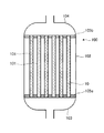
- FIG. 1 is a schematic view schematically showing an example of a fixed-bed multi-tube reactor.
- FIG. 2 is a graph showing the relationship between the value A of Examples and Comparative Examples and the variation in apparent density.
- the molding catalyst according to one embodiment of the present invention satisfies the following formula (1).
- the variation in the filling state when the molding catalyst is filled in the reaction tube is reduced.
- the variation in the filled state can be evaluated by evaluating the variation in the apparent specific gravity by the method described in the examples.
- W AV / W C is the average weight of the shaped catalyst (W AV), a ratio of the virtual cylinder the weight of the shaped catalyst (W C).
- W AV / W C sometimes described as a value A.
- the value A is an index showing the degree of the corners of the cylinder molding catalyst, and the smaller the value A, the more the corners of the cylinder molding catalyst are taken and the size is smaller than that of the cylinder.
- the value A can be adjusted, for example, by manufacturing a molding catalyst by adjusting the degree to which the angle of the catalyst molded into a cylindrical shape is taken.
- the value A can be adjusted by treating the catalyst formed in a cylindrical shape with a kneader such as a non-blowing kneader for an appropriate time. For example, as the processing time by the kneader is increased, the value A tends to be smaller. The value A tends to be larger as the processing time by the kneader is shortened.
- WAV W tot / n (2)
- W tot represents the total weight of n arbitrarily selected molding catalysts. Therefore, W AV means the average weight of n shaped catalyst chosen arbitrarily.
- W C is obtained by the following equation (3).
- W C (V AV ⁇ ⁇ ) / (1 + V P ⁇ ⁇ ) (3)
- V AV represents the average of the volume obtained for each virtual cylinder the respective diameters of the major axis (L) of the high counsel minor (D) of n shaped catalyst chosen arbitrarily .. ⁇ represents the true density of the molding catalyst.
- V P represents the pore volume per unit weight of the shaped catalyst.
- the molding catalyst of the present embodiment has a substantially cylindrical shape, and has a cylindrical shape with rounded corners.
- the minor diameter (D) of the molding catalyst means the maximum diameter of the molding catalyst in a cross section perpendicular to the height direction (axial direction) of a substantially cylindrical shape.
- the major axis (L) of the molding catalyst means the longest diameter of the molding catalyst in the height direction (axial direction) of the substantially cylindrical shape.
- a conventionally known caliper, digital indicator, or the like can be used for measuring the major axis (L) and minor axis (D) of the molding catalyst. The measurement is performed on n samples (usually n is 50 or more) arbitrarily extracted.
- the virtual cylinder is a cylinder in which the major axis (L) of the molding catalyst is assumed to be the height and the minor axis (D) is assumed to be the diameter of the bottom surface.
- VAV is the average volume of individual virtual cylinders obtained with the major axis (L) of each arbitrarily selected molding catalyst as the height and the minor axis (D) as the diameter.
- the true density of the molding catalyst is a density obtained by dividing the weight of the molding catalyst by the true volume (the apparent volume of the molding catalyst minus the volume of the pores).
- the true density ( ⁇ ) of the molding catalyst can be measured by a liquid phase substitution method or a gas phase substitution method. Specifically, it can be measured by the liquid phase replacement method under the conditions described in the examples.
- the pore volume (Vp) per unit weight of the molding catalyst can be measured by a pore volume measuring device (eg, "Autopore III9420" manufactured by MICROMERITICS).
- a pore volume measuring device eg, "Autopore III9420" manufactured by MICROMERITICS.
- the size of the molding catalyst is not particularly limited, but the minor axis (D) of the molding catalyst is usually 5 mm or less from the viewpoint of further promoting the reaction by increasing the catalytic activity. preferable.
- the molding catalyst used in the present invention preferably has an appropriate size, and usually, its minor axis (D) is preferably 1 mm or more.
- the major axis (L) of the molding catalyst is usually 1 mm or more and 10 mm or less, preferably 3 mm or more and 7 mm or less.
- An example of the method for producing the molding catalyst of the present invention is a method of forming a cylindrical catalyst and then removing the corner portions of the cylindrical shape.
- Examples of the method for forming a cylindrical catalyst include a method by extrusion molding and tableting molding. In the case of extrusion molding, the extruded product may be cut to an appropriate length and used.
- the cylindrical catalyst obtained here has corner portions.
- the corner portion of the cylindrical shape is a corner portion formed on the bottom surface and the side surface of the cylinder.
- the cylindrical catalyst is subjected to a process of removing the corners (also referred to as cornering) using a rotating device or the like.
- the cornering of the catalyst can be performed by, for example, treating with a non-bubbling kneader (manufactured by Nissei Tokyo Office, NBK-1) at an arbitrary time and rotation speed.
- the operating time of the non-babbling kneader is preferably in the time range of 10 minutes or more and 150 minutes or less, and more preferably in the time range of 50 minutes or more and 130 minutes or less, from the viewpoint of manufacturing efficiency and cornering effect.
- the rotation speed of the non-babbling kneader is preferably in the range of 100 rotations / minute or more and 2000 rotations / minute or less, and more preferably 200 rotations / minute or more and 1000 rotations / minute from the viewpoint of maintaining the catalyst strength and the angle-cutting effect. It is as follows.
- the molding catalyst may be formed from any catalyst material.
- the catalyst material molded into the molding catalyst of the present invention may be a material consisting of only the catalytically active component, or may be a material containing the catalytically active component and a carrier supporting the catalytically active component.
- catalytically active component examples of the catalytically active component that can be contained in the catalyst material are not particularly limited, but (1) a known catalytically active component for producing chlorine by oxidizing hydrogen chloride with oxygen by a vapor phase oxidation method (eg, Catalytically active components containing elements such as copper element, chromium element, and ruthenium element) can be mentioned.
- a known catalytically active component for producing chlorine by oxidizing hydrogen chloride with oxygen by a vapor phase oxidation method eg, Catalytically active components containing elements such as copper element, chromium element, and ruthenium element
- catalysts containing a copper element include Deacon catalysts (catalysts containing copper chloride and potassium chloride and further containing various compounds).
- catalysts containing a chromium element include catalysts containing chromium oxide (for example, Japanese Patent Application Laid-Open No. 61-13602, Japanese Patent Application Laid-Open No. 61-275104, Japanese Patent Application Laid-Open No. 62-113701, Japanese Patent Application Laid-Open No. 62- (Catalyst described in Japanese Patent Publication No. 270405) and the like.
- catalysts containing ruthenium elements include catalysts containing ruthenium oxide (for example, JP-A-9-67103, JP-A-10-338502, JP-A-2000-281314, JP-A-2002-79093, (Catalysts described in JP-A-2002-292279).
- a catalyst containing a ruthenium element is preferable, and a catalyst containing ruthenium oxide is more preferable.
- ruthenium oxide there are ruthenium dioxide (RuO 2 ) having an oxidation number of +4 and ruthenium oxide having another oxidation number.
- the catalyst may contain various forms of ruthenium oxide having various oxidation numbers as ruthenium oxide.
- the catalyst containing ruthenium oxide preferably contains ruthenium dioxide (RuO 2 ) having an oxidation number of +4.
- the catalyst may be a catalyst consisting substantially only of ruthenium oxide, or may be a supported ruthenium oxide catalyst containing ruthenium oxide and a carrier supporting the ruthenium oxide.
- a supported ruthenium oxide catalyst is more preferred because high activity can be obtained even with a relatively small content of ruthenium oxide.
- An example of a method for producing a supported ruthenium oxide catalyst is a method in which a ruthenium compound is supported on a carrier and then calcined in an atmosphere of an oxygen-containing gas to obtain a catalyst.
- Examples of carriers include one or more of carriers such as oxides of elements selected from the group consisting of aluminum, silicon, titanium, zirconium, and niobium (which can be composite oxides), activated charcoal, and the like. Combinations can be mentioned.
- the carrier one or more selected from the group consisting of alumina, silica, titanium oxide, and zirconium oxide is preferable, and titanium oxide having a rutile-type crystal structure is more preferable.
- the weight ratio of ruthenium oxide / carrier in the supported ruthenium oxide catalyst is not particularly limited, but is preferably 0.1 / 99.9 to 20/80, and more preferably 0.5 / 99.5 to 15/85. Such a weight ratio can be adjusted by adjusting the ratio of the ruthenium compound and the carrier used in the production of the supported ruthenium oxide catalyst. When the weight ratio is at least the lower limit value, the catalytic activity can be made sufficient, while when it is at least the upper limit value, the catalyst cost can be reduced.
- the supported ruthenium oxide catalyst can be suitably used in a gas phase oxidation method for obtaining chlorine from hydrogen chloride and oxygen.
- Molding to oxidize hydrogen halides with oxygen by forming the molding catalysts from catalytic materials containing catalytically active ingredients for oxidizing hydrogen halides with oxygen, such as ruthenium oxide catalysts.
- Catalytic materials containing catalytically active ingredients for oxidizing hydrogen halides with oxygen such as ruthenium oxide catalysts.
- the titania carrier may be a titania carrier composed of rutile-type titania (titania having a rutile-type crystal structure), anatase-type titania (titania having an anatase-type crystal structure), amorphous titania, or the like. It may be a rutile carrier composed of a mixture of these.
- a titania carrier composed of rutile-type titania and / or anatase-type titania is preferable, and among them, the ratio of rutile-type titania to rutile-type titania and anatase-type titania in the titania carrier (hereinafter, may be referred to as rutile-type titania ratio) is 50.
- % Or more of the titania carrier is preferred, 70% or more of the titania carrier is more preferred, and 90% or more of the titania carrier is even more preferred.
- the higher the ratio of rutile-type titania the more the thermal stability of the supported ruthenium oxide tends to be improved, and the better the catalytic activity.
- the rutile-type titania ratio can be measured by an X-ray diffraction method (hereinafter referred to as the XRD method) and is represented by the following formula (a).
- IR Intensity of diffraction line showing rutile-type titania (110) plane
- IA Intensity of diffraction line showing anatase-type titania (101) plane
- the sodium content in the titania carrier is preferably 200 ppm by weight or less, and the calcium content is preferably 200 ppm by weight or less. Further, the total alkali metal element content in the titania carrier is more preferably 200% by weight ppm or less, and the total alkali earth metal element content in the titania carrier is more preferably 200% by weight ppm or less. preferable.
- the contents of these alkali metal elements and alkaline earth metal elements can be determined by, for example, inductively coupled high-frequency plasma emission spectroscopic analysis (hereinafter, may be referred to as ICP analysis method), atomic absorption spectrometry, ion chromatography analysis, and the like. It can be measured, preferably by ICP spectroscopy.
- the titania carrier may contain oxides such as ⁇ -alumina, silica, zirconia, and niobium oxide. It is preferable that the titania carrier is substantially free of alumina having a high specific surface area. The presence of alumina having a high specific surface area in the titania carrier may cause the sulfur component and the oxidized sulfur component to be easily adsorbed and / or absorbed by the supported ruthenium oxide, which may reduce the activity of the catalyst. Since ⁇ -alumina has a low BET specific surface area, adsorption and / or absorption of sulfur components and oxidized sulfur components is unlikely to occur. That is, even if the carrier contains ⁇ -alumina, the problem is unlikely to occur.
- Examples of the alumina having a high specific surface area include those having a specific surface area of 10 to 500 m 2 / g, preferably 20 to 350 m 2 / g.
- the specific surface area of alumina can be measured by the nitrogen adsorption method (BET method), and is usually measured by the BET one-point method.
- the specific surface area of the titania carrier can be measured by the nitrogen adsorption method (BET method), and is usually measured by the BET 1-point method.
- the specific surface area obtained by the measurement is preferably 5 to 300 m 2 / g, more preferably 5 to 50 m 2 / g. If the specific surface area is too high, the titania carrier and ruthenium oxide in the obtained supported ruthenium oxide are likely to be sintered, and the thermal stability may be lowered. On the other hand, if the specific surface area is too low, the ruthenium oxide in the obtained supported ruthenium oxide is difficult to disperse, and the catalytic activity may be lowered.
- Ruthenium oxide is supported on the above-mentioned titania carrier.
- the support of ruthenium oxide on the titania carrier is carried out, for example, after the titania carrier is contact-treated with a solution containing a ruthenium compound and a solvent, until the solvent content reaches 0.10 to 15% by weight based on the weight of the titania carrier. It is carried out by drying, and then holding the obtained dried product in a state containing 1.0 to 15% by weight of a solvent based on the weight of the titania carrier, and then firing in an oxidizing gas atmosphere.
- ruthenium compound examples include halides such as RuCl 3 , RuBr 3 , halogenates such as K 3 RuCl 6 , K 2 RuCl 6 , and oxo salts such as K 2 RuO 4 and Na 2 RuO 4.
- Oxyhalides such as Ru 2 OCl 4 , Ru 2 OCl 5 , Ru 2 OCl 6 , K 2 [RuCl 5 (H 2 O) 4 ], [RuCl 2 (H 2 O) 4 ] Cl, K 2 [ Harogeno complexes such as Ru 2 OCl 10 ], Cs 2 [Ru 2 OCl 4 ], [Ru (NH 3 ) 5 H 2 O] Cl 2 , [Ru (NH 3 ) 5 Cl] Cl 2 , [Ru (NH 3) 5 Cl] Cl 2.
- the ratio of the titania carrier and the ruthenium compound used can be adjusted as appropriate.
- the weight ratio of the ruthenium oxide / titania carrier in the supported ruthenium oxide obtained after firing is preferably 0.1 / 99.9 to 20.0 / 80.0, more preferably 0.3 / 99. It may be appropriately adjusted so as to be 7 to 10.0 / 90.0, more preferably 0.5 / 99.5 to 5.0 / 95.0. If the amount of ruthenium oxide is too small, the catalytic activity may not be sufficient, and if it is too large, it is disadvantageous in terms of cost.
- the ruthenium compound is supported on the titania carrier by the contact treatment between the titania carrier and the solution containing the ruthenium compound and the solvent.
- the solvent include water, alcohol, nitrile, and the like, and if necessary, two or more of them may be used.
- the water highly pure water such as distilled water, ion-exchanged water, and ultrapure water is preferable. If the water used contains a large amount of impurities, such impurities may adhere to the catalyst and reduce the activity of the catalyst.
- Examples of the alcohol include alcohols having 1 to 6 carbon atoms such as methanol, ethanol, n-propanol, isopropanol, hexanol and cyclohexanol.
- Examples of the nitrile include nitriles having 1 to 6 carbon atoms such as acetonitrile, propionitrile, and benzonitrile.
- the amount of the solvent contained in the solution is preferably 70% by volume or more of the total pore volume of the titania carrier used minus the volume of the ruthenium compound to be supported.
- the upper limit is not particularly limited, but if the amount of the solvent used is too large, it tends to take a long time to dry, so it is preferably about 120% by volume or less.
- the temperature during the treatment is usually 0 to 100 ° C., preferably 0 to 50 ° C.
- the pressure during the treatment is usually 0.1 to 1 MPa, preferably atmospheric pressure.
- the contact treatment can be carried out in an air atmosphere or in an atmosphere of an inert gas such as nitrogen, helium, argon or oxygen dioxide, and at this time, it may be carried out in an atmosphere containing water vapor.
- Examples of the contact treatment include impregnation and immersion.
- a method of contacting the titania carrier with a solution containing a ruthenium compound and a solvent for example, (A) a method of impregnating the titania carrier with a solution containing the ruthenium compound and the solvent, and (B) a solution of the titania carrier containing the ruthenium compound and the solvent. Examples thereof include a method of immersing in a solvent, and the method (A) described above is preferable.
- the ruthenium compound is supported on the titania carrier by the contact treatment.
- the solvent is usually added to the titania carrier so that the content of the solvent exceeds 15% by weight based on the weight of the titania carrier. The usage is adjusted.
- the content of the obtained titania carrier containing the ruthenium compound and the solvent is usually 0.10 to 15% by weight based on the weight of the titania carrier. Dry until it becomes.
- the temperature is preferably 10 ° C. to 100 ° C.
- the pressure in drying is preferably 0.01 to 1 MPa, more preferably atmospheric pressure.
- the drying time is set as appropriate. Such drying can be carried out in an air atmosphere or in an atmosphere of an inert gas such as nitrogen, helium, argon or oxygen dioxide, and at this time, it may be carried out in an atmosphere containing water vapor.
- drying may be performed under the flow of air, an inert gas or a mixed gas of air and an inert gas, and at this time, the gas to be circulated may contain water vapor.
- the concentration of water vapor in the water vapor-containing gas is usually set in a range of less than the saturated water vapor amount under the drying conditions.
- the gas flow rate is 10 to 10000 / h in the standard state (0 ° C., 0.1 MPa conversion) as the space speed (GHSV) of the gas in the titania carrier. It is preferably 100 to 5000 / h, more preferably 100 to 5000 / h.
- the space velocity can be obtained by dividing the amount of gas (L / h) per hour passing through the device to be dried by the titania carrier capacity (L) in the device to be dried. ..
- the drying rate in the drying is appropriately set, but from the viewpoint of productivity, the evaporation rate of the solvent per 1 g of the titania carrier is preferably 0.01 g / h or more, more preferably 0.02 g / h or more, and 0. 03 g / h or more is more preferable.
- the evaporation rate of the solvent per 1 g of the titania carrier is preferably 0.50 g / h or less.
- the drying rate can be controlled by adjusting conditions such as temperature, pressure, time, and gas flow rate, but these conditions may be changed during drying to change the drying rate.
- the content of the solvent contained in the dried product obtained after the drying is usually 0.10 to 15% by weight, preferably 1.0 to 13% by weight, more preferably 2 based on the weight of the titania carrier. It is 0.0 to 7.0% by weight.
- the content of the solvent in the dried product based on the weight of the titania carrier is calculated by the following formula (b).
- the amount of residual solvent in the dried product is obtained by subtracting the amount of weight change before and after drying from the amount of the solvent used in the contact treatment. It can be obtained by
- drying with stirring means drying the titania carrier containing the ruthenium compound and the solvent in a fluid state rather than in a stationary state.
- stirring method include a method of rotating the drying container itself, a method of vibrating the drying container itself, a method of stirring with a stirrer provided in the drying container, and the like.
- the dried product thus obtained is usually held in a state of containing 1.0 to 15% by weight of a solvent based on the weight of the titania carrier.
- the holding is carried out in a state where the evaporation of the solvent contained in the dried product is suppressed, and the evaporation rate of the solvent is preferably less than 0.01 g / h per 1 g of the titania carrier, preferably 0.001 g / h or less. Is more preferable.
- the temperature is preferably 0 to 80 ° C, more preferably 5 to 50 ° C.
- the holding time is appropriately set depending on the content of the solvent and the holding temperature, but is preferably 10 hours or more, more preferably 15 hours or more.
- the holding is preferably carried out in a state containing 1.0 to 15% by weight of a solvent based on the weight of the titania carrier, and may be carried out under closed conditions or open conditions. It may be carried out under gas circulation. Further, it may be held in the same device as when it was dried, or it may be transferred to another container and held after drying.
- the vaporized solvent is contained before the holding.
- the content of the solvent in the dried product is 1.0 to 1.0 based on the weight of the titania carrier, depending on the method of circulating the gas to bring it into contact with the dried product, or the method of leaving it in the air when the solvent is water. It is preferable that the content is within the range of 15% by weight before being subjected to the holding.
- the oxidizing gas is a gas containing an oxidizing substance, and examples thereof include an oxygen-containing gas.
- the oxygen concentration is usually about 1 to 30% by volume.
- air or pure oxygen is usually used, and if necessary, it is diluted with an inert gas or water vapor. Of these, air is preferable as the oxidizing gas.
- the firing temperature is usually 100 to 500 ° C, preferably 200 to 400 ° C.
- the firing may be carried out after the holding and further drying until the solvent content in the dried product becomes less than 1.0% by weight based on the weight of the titania carrier, or after the holding, reduction. It may be carried out after the treatment, or after the holding, it is further dried until the content of the solvent in the dried product becomes less than 1.0% by weight based on the weight of the titania carrier, and then the reduction treatment is carried out. You may go from.
- a drying method a conventionally known method can be adopted, the temperature of which is usually about room temperature to about 100 ° C., and the pressure thereof is usually 0.001 to 1 MPa, preferably atmospheric pressure.
- Such drying can be carried out in an air atmosphere or in an atmosphere of an inert gas such as nitrogen, helium, argon or oxygen dioxide, and at this time, it may be carried out in an atmosphere of an inert gas containing water vapor.
- reduction treatment include reduction treatments described in JP-A-2000-229239, JP-A-2000-254502, JP-A-2000-281314, JP-A-2002-79093, and the like.
- the oxidation number of ruthenium in the supported ruthenium oxide is usually +4, and the ruthenium oxide is usually in the form of ruthenium dioxide (RuO 2 ), but other oxidation numbers of ruthenium. Alternatively, other forms of ruthenium oxide may be included.
- catalyst material (2) As another example of the catalytically active ingredient that can be contained in the catalytic material, (2) a catalytically active ingredient for obtaining methacrolein from isobutylene and oxygen by a vapor phase oxidation method, and further, an element such as a molybdenum element is used.
- Catalytically active ingredients including).
- the catalyst containing such a catalytically active component include the oxidation catalysts described in JP-A-2000-351744, JP-A-2010-188276, JP-A-2003-10690, and JP-A-2007-260588. These catalysts can be produced by conventionally known methods (for example, the methods described in the above-mentioned publication).
- the molding catalyst can be used by being housed in an arbitrary reactor, but since the effect of the molding catalyst of the present invention is remarkably exhibited, it is preferable to use it by filling it in the reaction tube of a multi-tube reactor. Therefore, the molding catalyst is suitable for multi-tube reactors, especially for fixed-bed multi-tube reactors.
- FIG. 1 is a schematic view schematically showing an example of a fixed-bed multi-tube reactor.
- the fixed-bed multi-tube reactor 100 contains a plurality of reaction tubes 101, a cylindrical shell 102 for accommodating the reaction tubes 101, and a raw material connected to the lower end of the shell 102.
- a fixing member 105b for fixing the reaction tube 101 to the shell 102 at its upper end is provided.
- the fixed-bed multi-tube reactor 100 is usually used with the shell 102 installed so that the axis is substantially parallel to the vertical direction.
- the plurality of reaction tubes 101 are fixed to the shell 102 so that the axial direction is substantially parallel to the axial direction of the shell 102, and the inside of the reaction tube 101 is filled with the molding catalyst 10 and used.
- the fixed-bed multi-tube reactor 100 may be of a disk-and-doughnut type, a missing circle baffle type, or the like.
- the plurality of reaction tubes 101 are linearly extending tubes having substantially the same length and inner diameter as each other.
- the upper end of the reaction tube 101 is open, and the molding catalyst 10 is filled and used from this opening.
- the multiple reaction tubes can be coiled.
- the reaction tube 101 is filled with a molding catalyst 10 (for example, a catalyst formed from a supported ruthenium oxide catalyst).
- a raw material for example, a gas containing hydrogen chloride and oxygen
- the raw material introduction unit 103 is introduced from the raw material introduction unit 103 and passed through the inside of the reaction tube 101 filled with the molding catalyst 10.
- the raw material comes into contact with the molding catalyst 10 and reacts to be converted into a product (for example, chlorine gas).
- the obtained product is collected by the product recovery unit 104 and taken out of the fixed-bed multi-tube reactor 100.
- the molding catalyst can be used in any production method depending on the catalytically active component contained.
- the molding catalyst formed from the supported ruthenium oxide catalyst as a material can be suitably used as a catalyst for oxidizing hydrogen halide with oxygen to obtain halogen.
- the molding catalyst can be used in a method for producing a halogen (preferably chlorine).
- a halogen preferably chlorine
- Molding catalyst (Example of catalyst material (1)), it is more preferable to use a molding catalyst formed from the catalyst material.
- the method for producing a halogen according to an embodiment of the present invention includes a step of obtaining a halogen using the molding catalyst.
- the production method of the present embodiment will be described by taking as an example a method of producing chlorine as a halogen.
- hydrogen chloride is oxidized by supplying hydrogen chloride and oxygen to each reaction tube of the fixed-bed multi-tube reactor.
- the fixed-bed multi-tube reactor is not particularly limited, but is described in the above [2.
- the fixed-bed multi-tube reactor described in [Usage of molding catalyst] can be used.
- Each reaction tube is filled with the molding catalyst, and chloride is formed by passing a gas containing hydrogen chloride and a gas containing oxygen through a layer of the molding catalyst (catalyst-filled layer) filled in each reaction tube. Oxidizes hydrogen.
- Examples of the gas containing hydrogen chloride are not particularly limited, and examples thereof include any gas containing hydrogen chloride, which is a gas generated by the reaction of hydrogen and chlorine; a gas generated by heating hydrochloric acid; a thermal decomposition of a chlorine compound. Gas generated by reaction or combustion reaction; gas produced by-product in the production of various compounds (eg, carbonylation reaction of organic compound with phosgen, chlorination reaction of organic compound with chlorine, production reaction of chlorofluoroalkane); Examples include combustion exhaust gas generated from an incinerator.
- the concentration of hydrogen chloride in the gas containing hydrogen chloride is preferably 10% by volume or more, more preferably 50% by volume or more, still more preferably 80% by volume or more, and usually 100% by volume or less.
- concentration of hydrogen chloride is at least the above lower limit value, the production efficiency is improved, and reaction operations such as separation of produced chlorine and recycling operation when unreacted oxygen is recycled can be simplified.
- the gas containing hydrogen chloride may contain impurities such as unreacted raw materials and reaction products in the reaction when the gas is generated.
- the concentration of impurities is preferably such that the concentration of hydrogen chloride in the gas is within the above-mentioned preferable range.
- the gas containing hydrogen chloride may contain other gases such as water vapor and an inert gas. However, for other gases such as water vapor and the inert gas, it is preferable that the concentration of hydrogen chloride in the gas is within the above-mentioned preferable range.
- the gas containing hydrogen chloride preferably contains water vapor because it can smooth the temperature distribution in the catalyst packed bed.
- gas containing oxygen air may be used or pure oxygen may be used.
- the halogen production method of the present embodiment may include an arbitrary step in addition to the step of obtaining the halogen using the molding catalyst.
- the halogen production method of the present embodiment may include a step of filling the reactor with a molding catalyst, a step of transferring the halogen produced in the reactor, and the like.
- part means “part by weight”.
- the physical characteristics of the molding catalyst used were measured and calculated by the following method.
- VAV ⁇ Average volume of virtual cylinder
- ⁇ Pore volume per unit weight of molding catalyst ( VP )> The catalyst to be used for the measurement was weighed from 0.6 to 1.2 g, dried in a dryer at 110 ° C. for 4 hours, and the weight after drying was precisely weighed to prepare a sample.
- This sample was set in the cell of a pore volume measuring device (“Autopore III9420” manufactured by MICROMERITICS), the inside of the cell system was reduced to 50 ⁇ mHg or less, the system was filled with mercury, and then the pressure was gradually applied to the cell. Was added, and the mercury injection amount at each pressure was measured with the mercury injection equilibrium waiting time set to 10 seconds.
- the total mercury injection amount (mL) when the pressure is applied from 0.007 MPa to 207 MPa is divided by the sample weight (g) to obtain the mercury injection amount per 1 g of the sample, which is fine per unit weight.
- ⁇ Catalyst cornering> The cornering of the catalyst was performed by treating with a non-bubbling kneader (NBK-1 manufactured by Nissei Tokyo Office) at a predetermined time and rotation speed.
- NBK-1 non-bubbling kneader
- Example 1 ⁇ Preparation of titanium oxide molded product> 100 parts of titania powder [F-1R manufactured by Showa Titanium Co., Ltd., ratio of rutile type titania 93%] and 2 parts of organic binder [YB-152A manufactured by Yuken Kogyo Co., Ltd.] are mixed, and then 29 parts of pure water. , Titania sol [CSB manufactured by Sakai Chemical Co., Ltd., titania content 40%] 12.5 parts was added and kneaded. This mixture was extruded into a noodle shape having a diameter of 3.0 mm ⁇ , dried at 60 ° C. for 2 hours, and then crushed to a length of about 3 to 5 mm. The obtained molded product was heated in air from room temperature to 600 ° C. over 1.7 hours, and then held at the same temperature for 3 hours and fired to obtain a white titanium oxide (titania) molded product.
- titania powder F-1R manufactured by Showa Titanium Co., Ltd., ratio of rutile
- FIG. 2 is a graph showing the relationship between the value A of Examples and Comparative Examples and the variation in apparent density.
- the molding catalyst of the example satisfying the formula (1) has a significantly smaller variation in apparent specific gravity than the molding catalyst of the comparative example.
- titanium oxide titanium oxide (titania) was used as the material for forming the molding catalyst, but as the material for forming the molding catalyst, a material containing various other components having catalytic activity (for example, a titania carrier).
- a ruthenium oxide catalyst on which ruthenium oxide is supported it is possible to obtain a molding catalyst having various catalytic activities and in which the degree of variation in the filling state when filling the reaction tube is reduced. Can be done.
- Molding catalyst 100 Fixed-bed multi-tube reactor 101 Reaction tube 102 Shell 103 Raw material introduction section 104 Product recovery section 105a, 105b Fixing member
Landscapes
- Chemical & Material Sciences (AREA)
- Organic Chemistry (AREA)
- Engineering & Computer Science (AREA)
- Materials Engineering (AREA)
- Chemical Kinetics & Catalysis (AREA)
- Inorganic Chemistry (AREA)
- Catalysts (AREA)
Abstract
L'invention concerne un catalyseur de moulage de formule (1). (1) : 0,800 ≤ WAV/WC ≤ 0,875, dans la formule (1), WAV est obtenu par la formule (2), et WC est obtenu par la formule (3). (2) : WAV = Wtot/n (3) : WC = (VAV·ρ)/(1 + VP·ρ), dans la formule (2), Wtot représente le poids total de n catalyseurs de moulage arbitrairement sélectionnés. Dans la formule (3), VAV représente la moyenne des volumes de cylindres virtuels ayant respectivement les longueurs (L) des n catalyseurs de moulage arbitrairement sélectionnés en tant que hauteurs, tout en ayant les chapelets (D) des n catalyseurs de moulage en tant que diamètres ; ρ représente la densité réelle des catalyseurs de moulage ; et VP représente le volume de pores par unité de poids des catalyseurs de moulage.
Priority Applications (5)
| Application Number | Priority Date | Filing Date | Title |
|---|---|---|---|
| CN202180026045.4A CN115362020B (zh) | 2020-04-01 | 2021-01-28 | 成形催化剂和卤素的制造方法 |
| KR1020227027556A KR102991189B1 (ko) | 2020-04-01 | 2021-01-28 | 성형 촉매 및 할로겐의 제조 방법 |
| US17/793,977 US20230092065A1 (en) | 2020-04-01 | 2021-01-28 | Molding catalyst and method for producing halogen |
| EP21779149.0A EP4129477A4 (fr) | 2020-04-01 | 2021-01-28 | Catalyseur de moulage et procédé de production d'halogène |
| JP2021514636A JP7702351B2 (ja) | 2020-04-01 | 2021-01-28 | 成形触媒およびハロゲンの製造方法 |
Applications Claiming Priority (2)
| Application Number | Priority Date | Filing Date | Title |
|---|---|---|---|
| JP2020066236 | 2020-04-01 | ||
| JP2020-066236 | 2020-04-01 |
Publications (1)
| Publication Number | Publication Date |
|---|---|
| WO2021199633A1 true WO2021199633A1 (fr) | 2021-10-07 |
Family
ID=77927930
Family Applications (1)
| Application Number | Title | Priority Date | Filing Date |
|---|---|---|---|
| PCT/JP2021/003003 Ceased WO2021199633A1 (fr) | 2020-04-01 | 2021-01-28 | Catalyseur de moulage et procédé de production d'halogène |
Country Status (6)
| Country | Link |
|---|---|
| US (1) | US20230092065A1 (fr) |
| EP (1) | EP4129477A4 (fr) |
| JP (1) | JP7702351B2 (fr) |
| KR (1) | KR102991189B1 (fr) |
| CN (1) | CN115362020B (fr) |
| WO (1) | WO2021199633A1 (fr) |
Citations (19)
| Publication number | Priority date | Publication date | Assignee | Title |
|---|---|---|---|---|
| JPS61136902A (ja) | 1984-12-03 | 1986-06-24 | Mitsui Toatsu Chem Inc | 塩素の製造方法 |
| JPS61275104A (ja) | 1985-05-28 | 1986-12-05 | Mitsui Toatsu Chem Inc | 塩素の製造方法 |
| JPS62113701A (ja) | 1985-11-14 | 1987-05-25 | Mitsui Toatsu Chem Inc | 塩素の製造方法 |
| JPS62270405A (ja) | 1986-05-19 | 1987-11-24 | Mitsui Toatsu Chem Inc | 塩素の製造方法 |
| JPH01228940A (ja) * | 1988-02-09 | 1989-09-12 | Hoechst Ag | 酢酸ビニルの製造方法 |
| JPH0967103A (ja) | 1995-05-18 | 1997-03-11 | Sumitomo Chem Co Ltd | 塩素の製造方法 |
| JPH10338502A (ja) | 1996-10-31 | 1998-12-22 | Sumitomo Chem Co Ltd | 塩素の製造方法 |
| JP2000229239A (ja) | 1998-04-07 | 2000-08-22 | Sumitomo Chem Co Ltd | 担持酸化ルテニウム触媒 |
| JP2000254502A (ja) | 1998-03-05 | 2000-09-19 | Sumitomo Chem Co Ltd | 担持酸化ルテニウム触媒の製造方法 |
| JP2000281314A (ja) | 1998-02-16 | 2000-10-10 | Sumitomo Chem Co Ltd | 塩素の製造方法 |
| JP2000351744A (ja) | 1999-04-09 | 2000-12-19 | Sumitomo Chem Co Ltd | メタクロレイン及びメタクリル酸の製造方法 |
| JP2002079093A (ja) | 1999-08-05 | 2002-03-19 | Sumitomo Chem Co Ltd | 担持酸化ルテニウム触媒、担持ルテニウム触媒の製造方法及び塩素の製造方法 |
| JP2002292279A (ja) | 2001-01-29 | 2002-10-08 | Sumitomo Chem Co Ltd | 担持酸化ルテニウム触媒および塩素の製造方法 |
| JP2003010690A (ja) | 2001-06-28 | 2003-01-14 | Sumitomo Chem Co Ltd | メタクリル酸製造用触媒、その製造方法およびメタクリル酸の製造方法 |
| JP2005144322A (ja) * | 2003-11-14 | 2005-06-09 | Nippon Shokubai Co Ltd | 無水ピロメリット酸製造用触媒および無水ピロメリット酸の製造方法 |
| JP2007260588A (ja) | 2006-03-29 | 2007-10-11 | Sumitomo Chemical Co Ltd | メタクリル酸製造用触媒の製造方法及びメタクリル酸の製造方法。 |
| JP2010052976A (ja) | 2008-08-28 | 2010-03-11 | Sumitomo Chemical Co Ltd | 塩素の製造方法 |
| JP2010188276A (ja) | 2009-02-18 | 2010-09-02 | Sumitomo Chemical Co Ltd | メタクロレインおよびメタクリル酸の製造触媒 |
| CN102909085A (zh) * | 2012-10-12 | 2013-02-06 | 安徽工程大学 | 一种加氢催化剂颗粒 |
Family Cites Families (20)
| Publication number | Priority date | Publication date | Assignee | Title |
|---|---|---|---|---|
| DE4017832A1 (de) * | 1990-06-02 | 1991-12-05 | Gillet Heinrich Gmbh | Keramik-distanzring |
| CN2357821Y (zh) * | 1998-06-25 | 2000-01-12 | 张爱云 | 球柱形瓷载体 |
| CN2388204Y (zh) * | 1998-07-07 | 2000-07-19 | 江西省萍乡市化工填料(集团)公司 | 一种多叶型凹凸椭球状孔式催化剂 |
| JP2002018290A (ja) * | 2000-07-12 | 2002-01-22 | Hitachi Metals Ltd | セラミックハニカム構造触媒用担体及びこれを用いたセラミックハニカム構造触媒コンバータ |
| CN2917777Y (zh) * | 2005-08-18 | 2007-07-04 | 丁章云 | 圆柱形催化剂载体 |
| CN201143429Y (zh) * | 2007-12-15 | 2008-11-05 | 醴陵市鑫辉化工填料有限公司 | 双球柱形瓷载体 |
| GB0816705D0 (en) * | 2008-09-12 | 2008-10-22 | Johnson Matthey Plc | Shaped heterogeneous catalysts |
| GB0816709D0 (en) * | 2008-09-12 | 2008-10-22 | Johnson Matthey Plc | Shaped heterogeneneous catalysts |
| GB0816703D0 (en) * | 2008-09-12 | 2008-10-22 | Johnson Matthey Plc | Shaped heterogeneous catalysts |
| JP5267305B2 (ja) * | 2008-11-21 | 2013-08-21 | 住友化学株式会社 | 塩素の製造方法 |
| BRPI1008622A2 (pt) * | 2009-02-26 | 2016-03-01 | Basf Se | catalisador para a oxidação catalítica de cloreto de hidrogênio com oxigênio para formar cloro compreendendo rutênio e para ou cálcio sobre um suporte, e, processo para a oxidação catalítica de cloreto de hidrogênio com oxigênio para formar cloro |
| CN201871380U (zh) * | 2010-11-18 | 2011-06-22 | 中国石油天然气股份有限公司 | 一种空心齿球形催化剂载体 |
| US8785670B2 (en) * | 2010-12-07 | 2014-07-22 | Basf Se | Process for the production of propylene oxide |
| CA2960555A1 (fr) * | 2014-09-17 | 2016-03-24 | Siluria Technologies, Inc. | Catalyseurs pour processus appliques au gaz naturel |
| CN204973935U (zh) * | 2015-07-23 | 2016-01-20 | 中海石油气电集团有限责任公司 | 一种四孔双弧面催化剂 |
| JP6873159B2 (ja) * | 2016-12-22 | 2021-05-19 | 三井化学株式会社 | 多孔質成形体の製造方法、α−オレフィン二量化用触媒の製造方法、α−オレフィン二量体の製造方法、多孔質成形体、及びα−オレフィン二量化用触媒 |
| CN208194411U (zh) * | 2018-01-08 | 2018-12-07 | 四川天一科技股份有限公司 | 一种用于直接还原铁工艺的烃类重整催化剂 |
| CN107999080A (zh) * | 2018-01-08 | 2018-05-08 | 四川天科技股份有限公司 | 一种用于直接还原铁工艺的烃类重整催化剂、制备及应用 |
| JP2020015258A (ja) * | 2018-07-26 | 2020-01-30 | イビデン株式会社 | 押出成形用金型及びハニカム構造体の製造方法 |
| GB201907062D0 (en) * | 2019-05-20 | 2019-07-03 | Johnson Matthey Plc | Catalyst preparation method |
-
2021
- 2021-01-28 EP EP21779149.0A patent/EP4129477A4/fr active Pending
- 2021-01-28 JP JP2021514636A patent/JP7702351B2/ja active Active
- 2021-01-28 WO PCT/JP2021/003003 patent/WO2021199633A1/fr not_active Ceased
- 2021-01-28 CN CN202180026045.4A patent/CN115362020B/zh active Active
- 2021-01-28 US US17/793,977 patent/US20230092065A1/en active Pending
- 2021-01-28 KR KR1020227027556A patent/KR102991189B1/ko active Active
Patent Citations (19)
| Publication number | Priority date | Publication date | Assignee | Title |
|---|---|---|---|---|
| JPS61136902A (ja) | 1984-12-03 | 1986-06-24 | Mitsui Toatsu Chem Inc | 塩素の製造方法 |
| JPS61275104A (ja) | 1985-05-28 | 1986-12-05 | Mitsui Toatsu Chem Inc | 塩素の製造方法 |
| JPS62113701A (ja) | 1985-11-14 | 1987-05-25 | Mitsui Toatsu Chem Inc | 塩素の製造方法 |
| JPS62270405A (ja) | 1986-05-19 | 1987-11-24 | Mitsui Toatsu Chem Inc | 塩素の製造方法 |
| JPH01228940A (ja) * | 1988-02-09 | 1989-09-12 | Hoechst Ag | 酢酸ビニルの製造方法 |
| JPH0967103A (ja) | 1995-05-18 | 1997-03-11 | Sumitomo Chem Co Ltd | 塩素の製造方法 |
| JPH10338502A (ja) | 1996-10-31 | 1998-12-22 | Sumitomo Chem Co Ltd | 塩素の製造方法 |
| JP2000281314A (ja) | 1998-02-16 | 2000-10-10 | Sumitomo Chem Co Ltd | 塩素の製造方法 |
| JP2000254502A (ja) | 1998-03-05 | 2000-09-19 | Sumitomo Chem Co Ltd | 担持酸化ルテニウム触媒の製造方法 |
| JP2000229239A (ja) | 1998-04-07 | 2000-08-22 | Sumitomo Chem Co Ltd | 担持酸化ルテニウム触媒 |
| JP2000351744A (ja) | 1999-04-09 | 2000-12-19 | Sumitomo Chem Co Ltd | メタクロレイン及びメタクリル酸の製造方法 |
| JP2002079093A (ja) | 1999-08-05 | 2002-03-19 | Sumitomo Chem Co Ltd | 担持酸化ルテニウム触媒、担持ルテニウム触媒の製造方法及び塩素の製造方法 |
| JP2002292279A (ja) | 2001-01-29 | 2002-10-08 | Sumitomo Chem Co Ltd | 担持酸化ルテニウム触媒および塩素の製造方法 |
| JP2003010690A (ja) | 2001-06-28 | 2003-01-14 | Sumitomo Chem Co Ltd | メタクリル酸製造用触媒、その製造方法およびメタクリル酸の製造方法 |
| JP2005144322A (ja) * | 2003-11-14 | 2005-06-09 | Nippon Shokubai Co Ltd | 無水ピロメリット酸製造用触媒および無水ピロメリット酸の製造方法 |
| JP2007260588A (ja) | 2006-03-29 | 2007-10-11 | Sumitomo Chemical Co Ltd | メタクリル酸製造用触媒の製造方法及びメタクリル酸の製造方法。 |
| JP2010052976A (ja) | 2008-08-28 | 2010-03-11 | Sumitomo Chemical Co Ltd | 塩素の製造方法 |
| JP2010188276A (ja) | 2009-02-18 | 2010-09-02 | Sumitomo Chemical Co Ltd | メタクロレインおよびメタクリル酸の製造触媒 |
| CN102909085A (zh) * | 2012-10-12 | 2013-02-06 | 安徽工程大学 | 一种加氢催化剂颗粒 |
Non-Patent Citations (1)
| Title |
|---|
| See also references of EP4129477A4 |
Also Published As
| Publication number | Publication date |
|---|---|
| EP4129477A1 (fr) | 2023-02-08 |
| US20230092065A1 (en) | 2023-03-23 |
| JPWO2021199633A1 (fr) | 2021-10-07 |
| KR20220151163A (ko) | 2022-11-14 |
| EP4129477A4 (fr) | 2023-12-13 |
| CN115362020A (zh) | 2022-11-18 |
| KR102991189B1 (ko) | 2026-07-14 |
| CN115362020B (zh) | 2024-06-11 |
| JP7702351B2 (ja) | 2025-07-03 |
Similar Documents
| Publication | Publication Date | Title |
|---|---|---|
| JP5382100B2 (ja) | 塩素の製造方法 | |
| US20070274897A1 (en) | Processes for the preparation of chlorine by gas phase oxidation | |
| JP7269349B2 (ja) | 塩素製造用酸化ルテニウム担持触媒の製造方法及びそれにより製造された触媒 | |
| JP2013139017A (ja) | 担持酸化ルテニウムの製造方法及び塩素の製造方法 | |
| JP5189954B2 (ja) | 塩素の製造方法 | |
| JP2014105128A (ja) | 塩素の製造方法 | |
| CN113164924A (zh) | 用于制氯的氯化氢氧化反应用催化剂及其制备方法 | |
| JP7702351B2 (ja) | 成形触媒およびハロゲンの製造方法 | |
| JP5833467B2 (ja) | 担持酸化ルテニウムの製造方法及び塩素の製造方法 | |
| CN102626623A (zh) | 氧化钌担载物的制造方法及氯的制造方法 | |
| JP2013146720A (ja) | 担持酸化ルテニウムの製造方法及び塩素の製造方法 | |
| JP2013169517A (ja) | 担持酸化ルテニウムの製造方法及び塩素の製造方法 | |
| JP2012161717A (ja) | 担持酸化ルテニウムの製造方法及び塩素の製造方法 | |
| WO2011108684A1 (fr) | Procédés de fabrication d'oxyde de ruthénium supporté et de fabrication de chlore | |
| JP5130155B2 (ja) | 塩素の製造方法 | |
| JP2012135722A (ja) | 担持酸化ルテニウムの製造方法及び塩素の製造方法 | |
| JP5333413B2 (ja) | 担持酸化ルテニウムの製造方法及び塩素の製造方法 | |
| JP2011241122A (ja) | 合成ガスの製造方法 |
Legal Events
| Date | Code | Title | Description |
|---|---|---|---|
| ENP | Entry into the national phase |
Ref document number: 2021514636 Country of ref document: JP Kind code of ref document: A |
|
| 121 | Ep: the epo has been informed by wipo that ep was designated in this application |
Ref document number: 21779149 Country of ref document: EP Kind code of ref document: A1 |
|
| NENP | Non-entry into the national phase |
Ref country code: DE |
|
| ENP | Entry into the national phase |
Ref document number: 2021779149 Country of ref document: EP Effective date: 20221102 |