WO2024171663A1 - Alliage de résistance à la déformation, jauge de contrainte et capteur - Google Patents
Alliage de résistance à la déformation, jauge de contrainte et capteur Download PDFInfo
- Publication number
- WO2024171663A1 WO2024171663A1 PCT/JP2024/000414 JP2024000414W WO2024171663A1 WO 2024171663 A1 WO2024171663 A1 WO 2024171663A1 JP 2024000414 W JP2024000414 W JP 2024000414W WO 2024171663 A1 WO2024171663 A1 WO 2024171663A1
- Authority
- WO
- WIPO (PCT)
- Prior art keywords
- strain
- atomic
- gauge
- alloy
- resistor
- Prior art date
- Legal status (The legal status is an assumption and is not a legal conclusion. Google has not performed a legal analysis and makes no representation as to the accuracy of the status listed.)
- Ceased
Links
Images


Classifications
-
- C—CHEMISTRY; METALLURGY
- C22—METALLURGY; FERROUS OR NON-FERROUS ALLOYS; TREATMENT OF ALLOYS OR NON-FERROUS METALS
- C22C—ALLOYS
- C22C27/00—Alloys based on rhenium or a refractory metal not mentioned in groups C22C14/00 or C22C16/00
- C22C27/06—Alloys based on chromium
-
- C—CHEMISTRY; METALLURGY
- C22—METALLURGY; FERROUS OR NON-FERROUS ALLOYS; TREATMENT OF ALLOYS OR NON-FERROUS METALS
- C22C—ALLOYS
- C22C30/00—Alloys containing less than 50% by weight of each constituent
-
- G—PHYSICS
- G01—MEASURING; TESTING
- G01B—MEASURING LENGTH, THICKNESS OR SIMILAR LINEAR DIMENSIONS; MEASURING ANGLES; MEASURING AREAS; MEASURING IRREGULARITIES OF SURFACES OR CONTOURS
- G01B7/00—Measuring arrangements characterised by the use of electric or magnetic techniques
- G01B7/16—Measuring arrangements characterised by the use of electric or magnetic techniques for measuring the deformation in a solid, e.g. by resistance strain gauge
-
- G—PHYSICS
- G01—MEASURING; TESTING
- G01L—MEASURING FORCE, STRESS, TORQUE, WORK, MECHANICAL POWER, MECHANICAL EFFICIENCY, OR FLUID PRESSURE
- G01L1/00—Measuring force or stress, in general
- G01L1/20—Measuring force or stress, in general by measuring variations in ohmic resistance of solid materials or of electrically-conductive fluids; by making use of electrokinetic cells, i.e. liquid-containing cells wherein an electrical potential is produced or varied upon the application of stress
- G01L1/22—Measuring force or stress, in general by measuring variations in ohmic resistance of solid materials or of electrically-conductive fluids; by making use of electrokinetic cells, i.e. liquid-containing cells wherein an electrical potential is produced or varied upon the application of stress using resistance strain gauges
- G01L1/2287—Measuring force or stress, in general by measuring variations in ohmic resistance of solid materials or of electrically-conductive fluids; by making use of electrokinetic cells, i.e. liquid-containing cells wherein an electrical potential is produced or varied upon the application of stress using resistance strain gauges constructional details of the strain gauges
Definitions
- the present invention relates to alloys for strain resistors, strain gauges, and sensors.
- Strain gauges are known that are attached to a measurement object (strain generating body) to detect the strain of the measurement object.
- a measurement object strain generating body
- One example of the material that makes up a strain gauge is a strain resistor, whose resistance changes as it changes shape when subjected to an external force. Specifically, metal materials containing Ni, Cr, Cu, etc. are used.
- the strain resistor is formed, for example, in the form of a film on a substrate, and is formed into a desired pattern, such as a meandering pattern, using photolithography and etching techniques.
- Patent Document 1 proposes, as an example of a resistor for a strain gauge, a thin-film resistor for a strain gauge having a gauge factor of 10 or more and a temperature coefficient of resistance of ⁇ 100 [ppm/°C] or less, which contains chromium (Cr), oxygen (O) and nitrogen (N), is expressed by the general formula Cr100-xyOxNy , the composition ratios x and y satisfy the relationships of 3.0 ⁇ x ⁇ 15.0 and 1.0 ⁇ y ⁇ 10.0 in atomic %, and the chromium has a bcc structure with a (110) orientation.
- Cr chromium
- O oxygen
- N nitrogen
- the thin-film resistor described in Patent Document 1 has its temperature coefficient of resistance (TCR) reduced by optimizing the heat treatment included in the manufacturing process to adjust the orientation of chromium. This means that the temperature coefficient of resistance (TCR) of the thin-film resistor described in Patent Document 1 is susceptible to variations in the manufacturing process. For this reason, with the method disclosed in Patent Document 1, it was not easy to consistently create a strain resistor with a high gauge factor Gf and low susceptibility to temperature changes.
- the present invention aims to provide a strain gauge with a high gauge factor Gf and low susceptibility to temperature changes, using an approach different from that of Patent Document 1, and to make it possible to easily form a strain resistor in a strain gauge without requiring reactive gas components such as oxygen or nitrogen in the manufacturing process, and therefore using a general-purpose sputtering device or the like. It also aims to provide an alloy for a strain resistor that provides the strain resistor in such a strain gauge, and a sensor equipped with such a strain gauge.
- an alloy for a strain resistor is an alloy for a strain resistor having a composition of Cr100 -xyFexMy , where M is one or more elements selected from the group consisting of Nb, Mo, Ta, and W (hereinafter, also referred to as "element M").
- a Cr-Fe alloy can provide a strain resistor having a gauge factor Gf of 10 or more and a negative temperature coefficient of resistance TCR.
- a Cr-M alloy can provide a strain resistor having a gauge factor Gf of 10 or more and a positive temperature coefficient of resistance TCR.
- a strain resistor made of an alloy for a strain resistor having a composition of Cr 100-xy Fe x M y which is one of these alloys, can easily achieve a gauge factor Gf of 10 or more and a temperature coefficient of resistance TCR in the range of ⁇ 1000 ppm/°C.
- the gauge factor Gf and temperature coefficient of resistance TCR can be controlled by the alloy composition, precise control of the crystal structure is not required compared to the case of incorporating oxygen (O) and nitrogen (N) into Cr as disclosed in Patent Document 1. Therefore, by using the above-mentioned alloy for strain resistors, it is possible to obtain a strain resistor with a high gauge factor Gf and low susceptibility to temperature effects without increasing the manufacturing load, and therefore of high quality.
- the amount of Fe added, x is 0.8 atomic % or more and 11.2 atomic % or less.
- the amount of element M added, y is more than 0 atomic % and 7.7 atomic % or less.
- Another aspect of the present invention is a strain gauge having a film-shaped strain resistor having the alloy composition of the above-mentioned alloy for strain resistors.
- the film-shaped strain resistor may be made of a thin film formed by a film formation process such as sputtering, or may be made of a foil formed by mechanical processing such as rolling.
- the concept of "film-shaped” includes thin film shapes and foil shapes. From the viewpoint of stably achieving a high gauge factor Gf, it is preferable that the strain resistor of this strain gauge has a bcc structure.
- the above-mentioned strain gauge has a gauge factor Gf and an absolute value
- the present invention provides a sensor comprising a substrate and the above-described strain gauge provided on the substrate, the strain gauge serving as a detection means.
- the present invention provides a strain gauge that has a high gauge factor Gf and is not easily affected by temperature changes.
- the present invention also provides an alloy for a strain resistor that provides the strain resistor included in the strain gauge, and a sensor that includes the strain gauge.
- the strain resistor included in the strain gauge can be easily manufactured using a general-purpose sputtering device, etc.
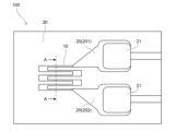
- FIG. 2 is a diagram showing an example of a strain sensor according to an embodiment of the present invention.
- 2 is a conceptual diagram showing a cross section taken along line AA in FIG. 1.
- 1 is a graph showing the relationship between the gauge factor Gf of a strain gauge having a strain resistor made of a Cr-X alloy and the amount of added X element.
- 1 is a graph showing the relationship between the temperature coefficient of resistance TCR of a strain gauge made of a Cr—X alloy and the amount of added X element.
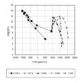
- 1 is a graph showing the relationship between the gauge factor Gf and the temperature coefficient of resistance TCR of a strain gauge having a strain resistor made of a Cr—X alloy.
- Example 6 is a graph in which the horizontal axis is changed to the absolute value of the temperature coefficient of resistance TCR in FIG. 5 .
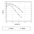
- 1 is a graph showing the results of Example 1 and Example 2 (the effect of changing the composition of a Cr—Fe—Ta alloy) showing the dependence of gauge factor Gf on the amount of Ta added.
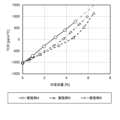
- 1 is a graph showing the results of Example 1 and Example 2 (the effect of changing the composition of a Cr—Fe—Ta alloy) showing the dependence of the temperature coefficient of resistance (TCR) on the amount of Ta added.
- 13 is a graph showing the result (change in film thickness) of Example 3, showing the dependence of gauge factor Gf on temperature coefficient of resistance TCR.
- 1 is a graph showing the results (type of M) of Examples 4 to 6, showing the dependence of gauge factor Gf on the amount of Ta added.
- 1 is a graph showing the results (types of M) of Examples 4 to 6, illustrating the dependence of the temperature coefficient of resistance (TCR) on the amount of Ta added.
- 1 is a graph showing the results of Example 1 and Example 2 (the effect of changing the composition of a Cr—Fe—Ta alloy) showing the absolute value dependency of the gauge factor Gf on the temperature coefficient of resistance TCR.
- 1 is a graph showing the results of Examples 4 to 6 (types of M) showing the absolute value dependency of the gauge factor Gf on the temperature coefficient of resistance TCR.
- the sensor 100 has a strain gauge 10 having a meandering pattern and an electrode 20 for passing electricity through the strain gauge 10.
- the strain gauge 10 and the electrode 20 are both formed on a substrate 30.
- the strain gauge 10 functions as a detection means.
- the sensor 100 may be a strain sensor that measures the strain of the strain gauge 10 itself based on a signal from the strain gauge 10, a deformation/displacement sensor that measures the degree of deformation of a member (strain body) to which the sensor 100 is attached, or a sensor that measures other physical quantities (pressure, speed, acceleration, etc.) based on the degree of deformation of the strain body.
- Non-limiting examples of the constituent material of the electrode 20 include Cu, Au, and alloys containing these.
- the electrode 20 comprises a first electrode 201 connected to one end of the strain gauge 10 and a second electrode 202 connected to the other end, and each of the first electrode 201 and the second electrode 202 is provided with a plating layer 21 for the purpose of increasing the solder adhesion strength.
- FIG. 2 is a conceptual diagram showing a cross section taken along line A-A in FIG. 1.
- the strain gauge 10 comprises a laminate 11 including a film-shaped strain resistor 12 and a protective layer 13 provided with a portion in contact with the strain resistor 12, and the laminate 11 forms a meandering pattern.
- the protective layer 13 is provided as necessary but is not essential, and may be made of Ta, for example.
- L is the length in the direction of current flow (current direction length) of the strain gauge 10 when no external force is applied (unloaded)
- ⁇ L is the change in the length of the strain gauge 10 in the current direction when an external force is applied to the strain gauge 10 (loaded) compared to when it is unloaded
- R is the resistance value of the strain gauge 10 when it is unloaded
- ⁇ R is the change in the resistance value of the strain gauge 10 when it is loaded compared to when it is unloaded.
- the strain resistor 12 is made of a Cr-Fe-M alloy having a composition of Cr100 -xyFexMy , where M is one or more elements (element M) selected from the group consisting of Nb, Mo, Ta, and W.
- the crystal structure of the strain resistor 12 is preferably a bcc structure from the viewpoint of increasing the gauge factor Gf of the strain resistor 12.
- a non-limiting example of the resistivity of the strain resistor 12 is 100 ⁇ cm or less.
- Table 1 shows the results of measuring the gauge factor Gf (measurement temperature: 25°C; same below) and temperature coefficient of resistance TCR for a strain gauge 10 having a strain resistor 12 made of a Cr-X alloy (element X is any one of Fe, Ta, Nb, Mo, or W; same below) while changing the amount of element X added.
- Figure 3 is a graph created from the results of Table 1 showing the relationship between the gauge factor Gf of a strain gauge 10 having a strain resistor 12 made of a Cr-X alloy and the amount of element X added.
- Figure 4 is a graph created from the results of Table 1 showing the relationship between the temperature coefficient of resistance TCR of a strain gauge 10 having a strain resistor 12 made of a Cr-X alloy and the amount of element X added.
- a Cr-Fe alloy can provide a strain gauge 10 having a gauge factor Gf of 10 or more and a negative temperature coefficient of resistance TCR.
- a Cr-X alloy other than a Cr-Fe alloy can provide a strain gauge 10 having a gauge factor Gf of 10 or more and a positive temperature coefficient of resistance TCR.
- a strain gauge 10 having a strain resistor 12 made of a strain resistor alloy having a composition of Cr 100-xy Fe x M y , which is one of these alloys can easily achieve a gauge factor Gf of 10 or more and a temperature coefficient of resistance TCR in the range of ⁇ 1000 ppm/°C.
- the gauge factor Gf and temperature coefficient of resistance TCR of the strain gauge 10 can be controlled by the alloy composition of the strain resistor 12, precise control of the crystal structure is not required compared to the case of incorporating oxygen (O) and nitrogen (N) into Cr as disclosed in Patent Document 1. Therefore, by using the above-mentioned alloy for the strain resistor, it is possible to obtain a high-quality strain gauge 10 that has a high gauge factor Gf and is less susceptible to temperature effects without increasing the manufacturing load.
- the amount of Fe added x is 0.8 atomic % or more and 11.2 atomic % or less.
- the gauge factor Gf of the strain gauge 10 is 10 or more. Therefore, by setting the amount of Fe added x in this range, it is easy to make the gauge factor Gf high and less susceptible to temperature changes even in the strain gauge 10 equipped with the strain resistor 12 made of the Cr-Fe-M alloy.
- the amount of Fe added x is 1.2 atomic % or more and 9.3 atomic % or less, and it may be more preferable that the amount of Fe added x is 3.1 atomic % or more and 7.6 atomic % or less.
- the amount of element M added (M amount) y is more than 0 atomic % and 7.7 atomic % or less. As shown in FIG. 3, when the M amount y is in the above range, the gauge factor Gf tends to increase for any of the elements constituting element M, and the temperature coefficient of resistance TCR is a positive value, making it easy to obtain a strain resistor 12 that has a high gauge factor Gf and is not easily affected by temperature changes.
- the M amount y is 0.5 atomic % or more and 3.5 atomic % or less, more preferably 1.1 atomic % or more and 3.1 atomic % or less, and particularly preferably 1.1 atomic % or more and 2.1 atomic % or less.
- the amount of M added y may be preferably 0.5 atomic % or more and 3.5 atomic % or less, more preferably 0.5 atomic % or more and 3.1 atomic % or less, and particularly preferably 1.1 atomic % or more and 2.0 atomic % or less.
- the amount of M added y may be preferably 2 atomic % or more and 14 atomic % or less, more preferably 3.3 atomic % or more and 13.5 atomic % or less, and particularly preferably 3.3 atomic % or more and 6.5 atomic % or less.
- the amount of M added y may preferably be 1 atomic % or more and 12 atomic % or less, more preferably 1.2 atomic % or more and 9.1 atomic % or less, and particularly preferably 4.1 atomic % or more and 7.7 atomic % or less.
- the gauge factor Gf is closely related to the Neel temperature (Tn) of the Cr-based material, and it is believed that when the amount of Fe or M added is excessively large, the decrease in the gauge factor Gf is caused by Tn deviating from the appropriate temperature range.
- the sum x+y of the amount of Fe added and the amount of M added depends on the type of constituent element of element M, but in some cases it may be preferable for it to be 11 atomic % or less, in some cases it may be more preferable for it to be 10 atomic % or less, and in some cases it may be particularly preferable for it to be 6 atomic % or less.
- the ratio of the amount of M added y to the sum (x+y) of the amount of Fe added x and the amount of M added y (y/(x+y), unit: %) depends on the type of element that constitutes element M, but may be preferably 55% or less, more preferably 50% or less, and particularly preferably 40% or less.
- Fig. 5 is a graph showing the relationship between the gauge factor Gf and the temperature coefficient of resistance TCR of a Cr-X alloy.
- Fig. 6 is a graph in which the horizontal axis of Fig. 5 is changed to the absolute value of the temperature coefficient of resistance TCR (unit: ppm/°C).
- Fe is an element whose behavior is significantly different from that of element M, and in particular, the change in the temperature coefficient of resistance TCR is significantly different from that of element M.
- the gauge factor Gf and the absolute value of the temperature coefficient of resistance TCR in the Cr-Fe alloy generally satisfy the following formula (a). Gf ⁇ 0.0056 ⁇
- Equation f0 shown by the dashed line in Figure 6, shows the case where the above equation (a) has an equal sign, and is a mathematical formula obtained by linear approximation using the results in Table 1 where the Fe addition amount x is 1.2 atomic % to 5.9 atomic %. Cr-Fe alloys are unable to reach the region in the upper left of the graph compared to equation f0, that is, the region where the gauge factor Gf is high and the absolute value of the temperature coefficient of resistance TCR is low.
- the Cr-Fe-M alloy according to this embodiment can achieve a range that cannot be achieved by a Cr-Fe alloy, that is, can satisfy the following formula (1).
- the Cr-Fe-M alloy according to this embodiment can, in a preferred example, reach the upper left region with the boundary line being the formula f1 shown by the solid line in Fig. 6. That is, the Cr-Fe-M alloy according to this embodiment can, in a preferred example, satisfy the following formula (2). Gf ⁇ 0.0056 ⁇
- the thickness of the strain resistor 12 of the strain gauge 10 is not limited. As shown in the examples described later, the thickness of the strain resistor 12 may have a positive correlation with the gauge factor Gf and the temperature coefficient of resistance TCR. In that case, the thickness of the strain resistor 12 can be changed to match the desired gauge factor Gf and temperature coefficient of resistance TCR. In other words, the thickness of the strain resistor 12 can be positioned as an adjustment factor for the characteristics of the strain resistor 12. The thickness of the strain resistor 12 can be adjusted in the range from a thin film of several tens of nm to a foil of several tens of ⁇ m by appropriately setting the manufacturing method.
- the method for manufacturing the strain resistor 12 according to this embodiment is not limited. As described above, since the strain resistor 12 is made of the alloy for strain resistors according to this embodiment, it can be manufactured by a known film formation method such as sputtering, or by mechanical processing such as rolling.
- an alloy having a composition corresponding to the composition of the strain resistor 12 to be manufactured may be used as the target, or a target consisting of tiled pure metals of Cr, Fe, and M may be used to adjust the composition of the strain resistor 12.
- a target consisting of tiled pure metals of Cr, Fe, and M may be used to adjust the composition of the strain resistor 12.
- two or more targets may be used for simultaneous sputtering, and the composition of the strain resistor 12 may be adjusted by adjusting the amount of power applied to each of them.
- the thickness may be preferably 300 nm or less.
- the thickness of the strain resistor 12 is too small, the resistance change due to strain may be too small and the function of the strain resistor 12 may not be properly performed.
- the thickness may be preferably 30 nm or more.
- the thin film resistor for strain gauge disclosed in Patent Document 1 is obtained by performing reactive sputtering in which oxygen molecules (O 2 ) and nitrogen molecules (N 2 ) are mixed into the atmosphere as reactive gas components, and the amount of oxygen (O) and nitrogen (N) contained in the formed film is adjusted, thereby obtaining the desired effect (gauge factor of 10 or more, resistance temperature coefficient of ⁇ 100 [ppm/° C.] or less).
- the strain resistor 12 according to this embodiment does not require adjustment of the supply amount of reactive gas components, and can be manufactured by forming an alloy film using a general-purpose sputtering device. Therefore, the strain resistor 12 according to this embodiment has excellent quality stability and excellent productivity.
- the thickness in the range of 1 ⁇ m to 10 ⁇ m, and more preferably in the range of 2 ⁇ m to 5 ⁇ m, from the viewpoints of ensuring ease of manufacturing, ease of handling, and processing accuracy of the thickness.
- the above-described embodiments are described to facilitate understanding of the present invention, and are not described to limit the present invention. Therefore, each element disclosed in the above embodiments is intended to include all design modifications and equivalents that fall within the technical scope of the present invention.
- the case where element M consists of one type of element includes the case where other elements are present to an extent that does not substantially affect the effects of the invention, and a specific example of such a case is the case where the mixture of other elements is unavoidable from the perspective of industrial production.
- Example 1 A strain gauge 10 was manufactured by sputtering on a substrate 30 made of a polyimide film, the substrate 30 being provided with a strain resistor 12 made of a Cr-Fe-Ta alloy.
- the composition of the Cr-Fe-Ta alloy is as shown in Table 2 (Example 1) and Table 3 (Example 2).
- the target value of the Fe additive amount x in Example 1 was 5 atomic %, and the target value of the Fe additive amount x in Example 2 was 3 atomic %.
- the thickness of the strain resistor 12 was 100 nm.
- the characteristics of the strain gauge 10 were evaluated using a sensor 100 equipped with the obtained strain gauge 10.
- the evaluation results are shown in Tables 2 and 3. Based on the results in these tables, the dependence of the gauge factor Gf on the amount of Ta added is shown in Figure 7, and the dependence of the temperature coefficient of resistance TCR on the amount of Ta added is shown in Figure 8.
- the strain gauge 10 provided in the sensor 100 produced in Examples 1 and 2.
- the gauge factor Gf exceeds 10 when the Ta addition amount y reaches 4.6 atomic % based on the trend shown in FIG. 7, and when the Ta addition amount y is 4.1 atomic % or less based on the measured values shown in Table 2.
- the temperature coefficient of resistance TCR of the strain gauge 10 is in the range of ⁇ 1000 ppm/° C. when the Ta addition amount y is 0.1 atomic % to 5.1 atomic % based on the trend shown in FIG.
- the gauge factor Gf exceeds 10 when the Ta additive amount y reaches 2.7 atomic % based on the trend shown in FIG. 7, and when the Ta additive amount y reaches 1.8 atomic % or less based on the measured values shown in Table 3.
- the temperature coefficient of resistivity TCR is in the range of ⁇ 1000 ppm/° C. when the Ta additive amount y reaches 4.0 atomic % based on the trend shown in FIG. 8, and when the Ta additive amount y reaches 3.8 atomic % or less based on the measured values shown in Table 3.
- Example 3 Using the same manufacturing method as in Example 1, sensors 100 were fabricated including strain resistors 12 made of Cr-Fe-Ta alloys having the same composition but different film thicknesses as shown in Table 4, and the characteristics of the strain gauges 10 were evaluated. The results are shown in Table 4 and Fig. 9.
- Fig. 9 is a graph showing the dependence of gauge factor Gf on temperature coefficient of resistance TCR, showing the results of Example 2 (changes in film thickness).
- Example 4 Strain gauges 10 were manufactured using the same manufacturing method as in Example 1, each of which was provided with a strain resistor 12 in which the type of alloy M was varied.
- Table 5 shows the case in which the alloy M was made of Nb (Example 4)
- Table 6 shows the case in which the alloy M was made of Mo (Example 5)
- Table 7 shows the case in which the alloy M was made of W (Example 6).
- the Fe addition amount x was aimed for 5 atomic %.
- the characteristics of the strain gauge 10 were evaluated using a sensor 100 equipped with the obtained strain gauge 10. The evaluation results are shown in Tables 5 to 7. Based on the results in these tables, the dependence of the gauge factor Gf on the amount of element M added is shown in Figure 10, and the dependence of the temperature coefficient of resistance TCR on the amount of element M added is shown in Figure 11.
- the strain gauge 10 (in which the Fe addition amount x of the Cr-Fe-M alloy constituting the strain resistor 12 is 5.0 atomic % or more and 5.3 atomic % or less) provided in the sensor 100 produced in Examples 4 to 6.
- the gauge factor Gf exceeds 10 when the amount of Nb added y reaches 3.8 atomic % based on the trend shown in FIG. 10, and reaches 3.0 atomic % or less based on the measured values shown in Table 5, and the temperature coefficient of resistance TCR is in the range of ⁇ 1000 ppm/° C. when the amount of Nb added y reaches 5.4 atomic % based on the trend shown in FIG.
- the gauge factor Gf of the strain gauge 10 exceeds 10 when the amount of Mo added y reaches 6.2 atomic % based on the trend shown in FIG. 10, and reaches 5.6 atomic % or less based on the measured values shown in Table 6, and the temperature coefficient of resistance TCR is in the range of ⁇ 1000 ppm/° C. when the amount of Mo added y reaches 5.4 atomic % based on the trend shown in FIG. Based on the trend shown in FIG. 10, the temperature coefficient of resistance TCR of the strain gauge 10 is in the range of ⁇ 1000 ppm/° C.
- the gauge factor Gf of the strain gauge 10 exceeds 10 up to the W additive amount y of 5.8 atomic % based on the trend shown in FIG. 10, and up to 5.6 atomic % based on the measured values shown in Table 7; and based on the trend shown in FIG. 11, the temperature coefficient of resistance TCR of the strain gauge 10 is in the range of ⁇ 1000 ppm/° C. up to the W additive amount y of 6.0 atomic %, and up to 0.8 atomic % to 5.9 atomic % based on the measured values shown in Table 7.
- FIG. 12 is a graph showing the results of Examples 1 and 2 (the effect of changing the composition of the Cr-Fe-Ta alloy) and the absolute value dependence of the gauge factor Gf on the temperature coefficient of resistance TCR.
- FIG. 13 is a graph showing the results of Examples 4 to 6 (type of element M) and the absolute value dependence of the gauge factor Gf on the temperature coefficient of resistance TCR. As shown in FIG. 12 and FIG. 13, it was confirmed that the results of all the Examples reached the region to the upper left of formula f0 in these figures, and further reached the region to the upper left of formula f1.
- sensor 10 strain gauge 11: laminate 12: strain resistor 13: protective layer 20: electrode 201: first electrode 202: second electrode 21: plating layer 30: substrate
Landscapes
- Chemical & Material Sciences (AREA)
- Engineering & Computer Science (AREA)
- Materials Engineering (AREA)
- Mechanical Engineering (AREA)
- Metallurgy (AREA)
- Organic Chemistry (AREA)
- Physics & Mathematics (AREA)
- General Physics & Mathematics (AREA)
- Measurement Of Length, Angles, Or The Like Using Electric Or Magnetic Means (AREA)
Abstract
Une jauge de contrainte selon un aspect de la présente invention a un facteur de jauge élevé Gf et est à peine affectée par des changements de température, et ladite jauge de contrainte comprend une résistance de contrainte en forme de film et a une composition d'alliage comprenant une composition constituée par Cr100-x-yFexMy. L'élément M est un ou plusieurs éléments choisis dans le groupe constitué par Nb, Mo, Ta et W. x, qui est le taux d'addition de Fe, peut être préférentiellement de 0,8 % atomique à 11, 2 % atomique, inclus. Y, qui est le taux d'addition M, peut de préférence être de 0 % atomique à 7,7 % atomiques, inclus.
Priority Applications (2)
| Application Number | Priority Date | Filing Date | Title |
|---|---|---|---|
| JP2025500717A JPWO2024171663A1 (fr) | 2023-02-16 | 2024-01-11 | |
| US19/277,938 US20250347569A1 (en) | 2023-02-16 | 2025-07-23 | Alloy for strain resistors, strain gauge, and sensor |
Applications Claiming Priority (2)
| Application Number | Priority Date | Filing Date | Title |
|---|---|---|---|
| JP2023022826 | 2023-02-16 | ||
| JP2023-022826 | 2023-02-16 |
Related Child Applications (1)
| Application Number | Title | Priority Date | Filing Date |
|---|---|---|---|
| US19/277,938 Continuation US20250347569A1 (en) | 2023-02-16 | 2025-07-23 | Alloy for strain resistors, strain gauge, and sensor |
Publications (1)
| Publication Number | Publication Date |
|---|---|
| WO2024171663A1 true WO2024171663A1 (fr) | 2024-08-22 |
Family
ID=92421476
Family Applications (1)
| Application Number | Title | Priority Date | Filing Date |
|---|---|---|---|
| PCT/JP2024/000414 Ceased WO2024171663A1 (fr) | 2023-02-16 | 2024-01-11 | Alliage de résistance à la déformation, jauge de contrainte et capteur |
Country Status (3)
| Country | Link |
|---|---|
| US (1) | US20250347569A1 (fr) |
| JP (1) | JPWO2024171663A1 (fr) |
| WO (1) | WO2024171663A1 (fr) |
Citations (3)
| Publication number | Priority date | Publication date | Assignee | Title |
|---|---|---|---|---|
| JPH0995751A (ja) * | 1995-10-03 | 1997-04-08 | Res Inst Electric Magnetic Alloys | cr基合金薄膜およびその製造法ならびにストレインゲージ |
| JPH10270201A (ja) * | 1997-03-21 | 1998-10-09 | Res Inst Electric Magnetic Alloys | Cr−N基歪抵抗膜およびその製造法ならびに歪センサ |
| JP2019074454A (ja) * | 2017-10-18 | 2019-05-16 | 公益財団法人電磁材料研究所 | 熱安定性に優れ、高歪ゲージ率を有する歪センサ用薄膜合金 |
-
2024
- 2024-01-11 WO PCT/JP2024/000414 patent/WO2024171663A1/fr not_active Ceased
- 2024-01-11 JP JP2025500717A patent/JPWO2024171663A1/ja active Pending
-
2025
- 2025-07-23 US US19/277,938 patent/US20250347569A1/en active Pending
Patent Citations (3)
| Publication number | Priority date | Publication date | Assignee | Title |
|---|---|---|---|---|
| JPH0995751A (ja) * | 1995-10-03 | 1997-04-08 | Res Inst Electric Magnetic Alloys | cr基合金薄膜およびその製造法ならびにストレインゲージ |
| JPH10270201A (ja) * | 1997-03-21 | 1998-10-09 | Res Inst Electric Magnetic Alloys | Cr−N基歪抵抗膜およびその製造法ならびに歪センサ |
| JP2019074454A (ja) * | 2017-10-18 | 2019-05-16 | 公益財団法人電磁材料研究所 | 熱安定性に優れ、高歪ゲージ率を有する歪センサ用薄膜合金 |
Also Published As
| Publication number | Publication date |
|---|---|
| JPWO2024171663A1 (fr) | 2024-08-22 |
| US20250347569A1 (en) | 2025-11-13 |
Similar Documents
| Publication | Publication Date | Title |
|---|---|---|
| JP6084393B2 (ja) | 歪センサおよび歪の測定方法 | |
| US9933321B2 (en) | High gage factor strain gage | |
| US5508676A (en) | Strain gauge on a flexible support and transducer equipped with said gauge | |
| US4100524A (en) | Electrical transducer and method of making | |
| CN115516122B (zh) | 铜合金条材及其制造方法、使用铜合金条材的电阻器用电阻材料以及电阻器 | |
| WO2024171663A1 (fr) | Alliage de résistance à la déformation, jauge de contrainte et capteur | |
| JP6908554B2 (ja) | 歪抵抗膜および歪センサ、ならびにそれらの製造方法 | |
| JPH0941100A (ja) | Fe−Cr−Si基合金およびその製造法ならびにストレインゲージ | |
| WO2024171664A1 (fr) | Jauge de contrainte et capteur | |
| JP2024054754A (ja) | 歪抵抗膜および物理量センサおよび歪抵抗膜の製造方法 | |
| JP6585679B2 (ja) | 熱安定性に優れ、高歪ゲージ率を有する歪センサ用薄膜合金 | |
| JP5408533B2 (ja) | ひずみゲージ用のFe−Ni−Cr系アイソエラスティック組成物、及び、該組成物を用いて製造されるひずみゲージ | |
| JP6840317B2 (ja) | 歪抵抗薄膜および当該歪抵抗薄膜を用いたセンサ | |
| KR101107306B1 (ko) | 압력센서용 금속 박막형 스트레인 게이지 및 이를 포함하는 압력센서 | |
| JP2019074452A (ja) | 薄膜ひずみセンサ材料および薄膜ひずみセンサ | |
| JPH0666162B2 (ja) | 歪ゲージ用薄膜抵抗体 | |
| JP4988938B2 (ja) | 感温感歪複合センサ | |
| JP6708538B2 (ja) | 熱安定性に優れた歪センサ用薄膜合金 | |
| JP2001110602A (ja) | 薄膜抵抗体形成方法及びセンサ | |
| JP7743266B2 (ja) | ひずみゲージおよびその製造方法 | |
| WO2023053606A1 (fr) | Capteur composite sensible à la température et sensible à la déformation | |
| JP2000331808A (ja) | 薄膜抵抗体形成方法及びこの方法により形成された薄膜抵抗体とこの薄膜抵抗体を用いた歪センサ | |
| JP5327651B2 (ja) | 電子部品用薄膜配線および薄膜配線形成用スパッタリングターゲット材 | |
| RU2750503C1 (ru) | Способ изготовления многослойной тонкопленочной гетероструктуры с заданной величиной удельного поверхностного сопротивления | |
| JP7732107B2 (ja) | 歪ゲージおよび歪センサ |
Legal Events
| Date | Code | Title | Description |
|---|---|---|---|
| 121 | Ep: the epo has been informed by wipo that ep was designated in this application |
Ref document number: 24756515 Country of ref document: EP Kind code of ref document: A1 |
|
| WWE | Wipo information: entry into national phase |
Ref document number: 2025500717 Country of ref document: JP |
|
| NENP | Non-entry into the national phase |
Ref country code: DE |
|
| 122 | Ep: pct application non-entry in european phase |
Ref document number: 24756515 Country of ref document: EP Kind code of ref document: A1 |