WO2024171663A1 - 歪抵抗体用合金、歪ゲージ、およびセンサ - Google Patents
歪抵抗体用合金、歪ゲージ、およびセンサ Download PDFInfo
- Publication number
- WO2024171663A1 WO2024171663A1 PCT/JP2024/000414 JP2024000414W WO2024171663A1 WO 2024171663 A1 WO2024171663 A1 WO 2024171663A1 JP 2024000414 W JP2024000414 W JP 2024000414W WO 2024171663 A1 WO2024171663 A1 WO 2024171663A1
- Authority
- WO
- WIPO (PCT)
- Prior art keywords
- strain
- atomic
- gauge
- alloy
- resistor
- Prior art date
- Legal status (The legal status is an assumption and is not a legal conclusion. Google has not performed a legal analysis and makes no representation as to the accuracy of the status listed.)
- Ceased
Links
Images


Classifications
-
- C—CHEMISTRY; METALLURGY
- C22—METALLURGY; FERROUS OR NON-FERROUS ALLOYS; TREATMENT OF ALLOYS OR NON-FERROUS METALS
- C22C—ALLOYS
- C22C27/00—Alloys based on rhenium or a refractory metal not mentioned in groups C22C14/00 or C22C16/00
- C22C27/06—Alloys based on chromium
-
- C—CHEMISTRY; METALLURGY
- C22—METALLURGY; FERROUS OR NON-FERROUS ALLOYS; TREATMENT OF ALLOYS OR NON-FERROUS METALS
- C22C—ALLOYS
- C22C30/00—Alloys containing less than 50% by weight of each constituent
-
- G—PHYSICS
- G01—MEASURING; TESTING
- G01B—MEASURING LENGTH, THICKNESS OR SIMILAR LINEAR DIMENSIONS; MEASURING ANGLES; MEASURING AREAS; MEASURING IRREGULARITIES OF SURFACES OR CONTOURS
- G01B7/00—Measuring arrangements characterised by the use of electric or magnetic techniques
- G01B7/16—Measuring arrangements characterised by the use of electric or magnetic techniques for measuring the deformation in a solid, e.g. by resistance strain gauge
-
- G—PHYSICS
- G01—MEASURING; TESTING
- G01L—MEASURING FORCE, STRESS, TORQUE, WORK, MECHANICAL POWER, MECHANICAL EFFICIENCY, OR FLUID PRESSURE
- G01L1/00—Measuring force or stress, in general
- G01L1/20—Measuring force or stress, in general by measuring variations in ohmic resistance of solid materials or of electrically-conductive fluids; by making use of electrokinetic cells, i.e. liquid-containing cells wherein an electrical potential is produced or varied upon the application of stress
- G01L1/22—Measuring force or stress, in general by measuring variations in ohmic resistance of solid materials or of electrically-conductive fluids; by making use of electrokinetic cells, i.e. liquid-containing cells wherein an electrical potential is produced or varied upon the application of stress using resistance strain gauges
- G01L1/2287—Measuring force or stress, in general by measuring variations in ohmic resistance of solid materials or of electrically-conductive fluids; by making use of electrokinetic cells, i.e. liquid-containing cells wherein an electrical potential is produced or varied upon the application of stress using resistance strain gauges constructional details of the strain gauges
Definitions
- the present invention relates to alloys for strain resistors, strain gauges, and sensors.
- Strain gauges are known that are attached to a measurement object (strain generating body) to detect the strain of the measurement object.
- a measurement object strain generating body
- One example of the material that makes up a strain gauge is a strain resistor, whose resistance changes as it changes shape when subjected to an external force. Specifically, metal materials containing Ni, Cr, Cu, etc. are used.
- the strain resistor is formed, for example, in the form of a film on a substrate, and is formed into a desired pattern, such as a meandering pattern, using photolithography and etching techniques.
- Patent Document 1 proposes, as an example of a resistor for a strain gauge, a thin-film resistor for a strain gauge having a gauge factor of 10 or more and a temperature coefficient of resistance of ⁇ 100 [ppm/°C] or less, which contains chromium (Cr), oxygen (O) and nitrogen (N), is expressed by the general formula Cr100-xyOxNy , the composition ratios x and y satisfy the relationships of 3.0 ⁇ x ⁇ 15.0 and 1.0 ⁇ y ⁇ 10.0 in atomic %, and the chromium has a bcc structure with a (110) orientation.
- Cr chromium
- O oxygen
- N nitrogen
- the thin-film resistor described in Patent Document 1 has its temperature coefficient of resistance (TCR) reduced by optimizing the heat treatment included in the manufacturing process to adjust the orientation of chromium. This means that the temperature coefficient of resistance (TCR) of the thin-film resistor described in Patent Document 1 is susceptible to variations in the manufacturing process. For this reason, with the method disclosed in Patent Document 1, it was not easy to consistently create a strain resistor with a high gauge factor Gf and low susceptibility to temperature changes.
- the present invention aims to provide a strain gauge with a high gauge factor Gf and low susceptibility to temperature changes, using an approach different from that of Patent Document 1, and to make it possible to easily form a strain resistor in a strain gauge without requiring reactive gas components such as oxygen or nitrogen in the manufacturing process, and therefore using a general-purpose sputtering device or the like. It also aims to provide an alloy for a strain resistor that provides the strain resistor in such a strain gauge, and a sensor equipped with such a strain gauge.
- an alloy for a strain resistor is an alloy for a strain resistor having a composition of Cr100 -xyFexMy , where M is one or more elements selected from the group consisting of Nb, Mo, Ta, and W (hereinafter, also referred to as "element M").
- a Cr-Fe alloy can provide a strain resistor having a gauge factor Gf of 10 or more and a negative temperature coefficient of resistance TCR.
- a Cr-M alloy can provide a strain resistor having a gauge factor Gf of 10 or more and a positive temperature coefficient of resistance TCR.
- a strain resistor made of an alloy for a strain resistor having a composition of Cr 100-xy Fe x M y which is one of these alloys, can easily achieve a gauge factor Gf of 10 or more and a temperature coefficient of resistance TCR in the range of ⁇ 1000 ppm/°C.
- the gauge factor Gf and temperature coefficient of resistance TCR can be controlled by the alloy composition, precise control of the crystal structure is not required compared to the case of incorporating oxygen (O) and nitrogen (N) into Cr as disclosed in Patent Document 1. Therefore, by using the above-mentioned alloy for strain resistors, it is possible to obtain a strain resistor with a high gauge factor Gf and low susceptibility to temperature effects without increasing the manufacturing load, and therefore of high quality.
- the amount of Fe added, x is 0.8 atomic % or more and 11.2 atomic % or less.
- the amount of element M added, y is more than 0 atomic % and 7.7 atomic % or less.
- Another aspect of the present invention is a strain gauge having a film-shaped strain resistor having the alloy composition of the above-mentioned alloy for strain resistors.
- the film-shaped strain resistor may be made of a thin film formed by a film formation process such as sputtering, or may be made of a foil formed by mechanical processing such as rolling.
- the concept of "film-shaped” includes thin film shapes and foil shapes. From the viewpoint of stably achieving a high gauge factor Gf, it is preferable that the strain resistor of this strain gauge has a bcc structure.
- the above-mentioned strain gauge has a gauge factor Gf and an absolute value
- the present invention provides a sensor comprising a substrate and the above-described strain gauge provided on the substrate, the strain gauge serving as a detection means.
- the present invention provides a strain gauge that has a high gauge factor Gf and is not easily affected by temperature changes.
- the present invention also provides an alloy for a strain resistor that provides the strain resistor included in the strain gauge, and a sensor that includes the strain gauge.
- the strain resistor included in the strain gauge can be easily manufactured using a general-purpose sputtering device, etc.
- FIG. 2 is a diagram showing an example of a strain sensor according to an embodiment of the present invention.
- 2 is a conceptual diagram showing a cross section taken along line AA in FIG. 1.
- 1 is a graph showing the relationship between the gauge factor Gf of a strain gauge having a strain resistor made of a Cr-X alloy and the amount of added X element.
- 1 is a graph showing the relationship between the temperature coefficient of resistance TCR of a strain gauge made of a Cr—X alloy and the amount of added X element.
- 1 is a graph showing the relationship between the gauge factor Gf and the temperature coefficient of resistance TCR of a strain gauge having a strain resistor made of a Cr—X alloy.
- Example 6 is a graph in which the horizontal axis is changed to the absolute value of the temperature coefficient of resistance TCR in FIG. 5 .
- 1 is a graph showing the results of Example 1 and Example 2 (the effect of changing the composition of a Cr—Fe—Ta alloy) showing the dependence of gauge factor Gf on the amount of Ta added.
- 1 is a graph showing the results of Example 1 and Example 2 (the effect of changing the composition of a Cr—Fe—Ta alloy) showing the dependence of the temperature coefficient of resistance (TCR) on the amount of Ta added.
- 13 is a graph showing the result (change in film thickness) of Example 3, showing the dependence of gauge factor Gf on temperature coefficient of resistance TCR.
- 1 is a graph showing the results (type of M) of Examples 4 to 6, showing the dependence of gauge factor Gf on the amount of Ta added.
- 1 is a graph showing the results (types of M) of Examples 4 to 6, illustrating the dependence of the temperature coefficient of resistance (TCR) on the amount of Ta added.
- 1 is a graph showing the results of Example 1 and Example 2 (the effect of changing the composition of a Cr—Fe—Ta alloy) showing the absolute value dependency of the gauge factor Gf on the temperature coefficient of resistance TCR.
- 1 is a graph showing the results of Examples 4 to 6 (types of M) showing the absolute value dependency of the gauge factor Gf on the temperature coefficient of resistance TCR.
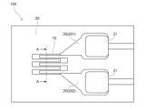
- the sensor 100 has a strain gauge 10 having a meandering pattern and an electrode 20 for passing electricity through the strain gauge 10.
- the strain gauge 10 and the electrode 20 are both formed on a substrate 30.
- the strain gauge 10 functions as a detection means.
- the sensor 100 may be a strain sensor that measures the strain of the strain gauge 10 itself based on a signal from the strain gauge 10, a deformation/displacement sensor that measures the degree of deformation of a member (strain body) to which the sensor 100 is attached, or a sensor that measures other physical quantities (pressure, speed, acceleration, etc.) based on the degree of deformation of the strain body.
- Non-limiting examples of the constituent material of the electrode 20 include Cu, Au, and alloys containing these.
- the electrode 20 comprises a first electrode 201 connected to one end of the strain gauge 10 and a second electrode 202 connected to the other end, and each of the first electrode 201 and the second electrode 202 is provided with a plating layer 21 for the purpose of increasing the solder adhesion strength.
- FIG. 2 is a conceptual diagram showing a cross section taken along line A-A in FIG. 1.
- the strain gauge 10 comprises a laminate 11 including a film-shaped strain resistor 12 and a protective layer 13 provided with a portion in contact with the strain resistor 12, and the laminate 11 forms a meandering pattern.
- the protective layer 13 is provided as necessary but is not essential, and may be made of Ta, for example.
- L is the length in the direction of current flow (current direction length) of the strain gauge 10 when no external force is applied (unloaded)
- ⁇ L is the change in the length of the strain gauge 10 in the current direction when an external force is applied to the strain gauge 10 (loaded) compared to when it is unloaded
- R is the resistance value of the strain gauge 10 when it is unloaded
- ⁇ R is the change in the resistance value of the strain gauge 10 when it is loaded compared to when it is unloaded.
- the strain resistor 12 is made of a Cr-Fe-M alloy having a composition of Cr100 -xyFexMy , where M is one or more elements (element M) selected from the group consisting of Nb, Mo, Ta, and W.
- the crystal structure of the strain resistor 12 is preferably a bcc structure from the viewpoint of increasing the gauge factor Gf of the strain resistor 12.
- a non-limiting example of the resistivity of the strain resistor 12 is 100 ⁇ cm or less.
- Table 1 shows the results of measuring the gauge factor Gf (measurement temperature: 25°C; same below) and temperature coefficient of resistance TCR for a strain gauge 10 having a strain resistor 12 made of a Cr-X alloy (element X is any one of Fe, Ta, Nb, Mo, or W; same below) while changing the amount of element X added.
- Figure 3 is a graph created from the results of Table 1 showing the relationship between the gauge factor Gf of a strain gauge 10 having a strain resistor 12 made of a Cr-X alloy and the amount of element X added.
- Figure 4 is a graph created from the results of Table 1 showing the relationship between the temperature coefficient of resistance TCR of a strain gauge 10 having a strain resistor 12 made of a Cr-X alloy and the amount of element X added.
- a Cr-Fe alloy can provide a strain gauge 10 having a gauge factor Gf of 10 or more and a negative temperature coefficient of resistance TCR.
- a Cr-X alloy other than a Cr-Fe alloy can provide a strain gauge 10 having a gauge factor Gf of 10 or more and a positive temperature coefficient of resistance TCR.
- a strain gauge 10 having a strain resistor 12 made of a strain resistor alloy having a composition of Cr 100-xy Fe x M y , which is one of these alloys can easily achieve a gauge factor Gf of 10 or more and a temperature coefficient of resistance TCR in the range of ⁇ 1000 ppm/°C.
- the gauge factor Gf and temperature coefficient of resistance TCR of the strain gauge 10 can be controlled by the alloy composition of the strain resistor 12, precise control of the crystal structure is not required compared to the case of incorporating oxygen (O) and nitrogen (N) into Cr as disclosed in Patent Document 1. Therefore, by using the above-mentioned alloy for the strain resistor, it is possible to obtain a high-quality strain gauge 10 that has a high gauge factor Gf and is less susceptible to temperature effects without increasing the manufacturing load.
- the amount of Fe added x is 0.8 atomic % or more and 11.2 atomic % or less.
- the gauge factor Gf of the strain gauge 10 is 10 or more. Therefore, by setting the amount of Fe added x in this range, it is easy to make the gauge factor Gf high and less susceptible to temperature changes even in the strain gauge 10 equipped with the strain resistor 12 made of the Cr-Fe-M alloy.
- the amount of Fe added x is 1.2 atomic % or more and 9.3 atomic % or less, and it may be more preferable that the amount of Fe added x is 3.1 atomic % or more and 7.6 atomic % or less.
- the amount of element M added (M amount) y is more than 0 atomic % and 7.7 atomic % or less. As shown in FIG. 3, when the M amount y is in the above range, the gauge factor Gf tends to increase for any of the elements constituting element M, and the temperature coefficient of resistance TCR is a positive value, making it easy to obtain a strain resistor 12 that has a high gauge factor Gf and is not easily affected by temperature changes.
- the M amount y is 0.5 atomic % or more and 3.5 atomic % or less, more preferably 1.1 atomic % or more and 3.1 atomic % or less, and particularly preferably 1.1 atomic % or more and 2.1 atomic % or less.
- the amount of M added y may be preferably 0.5 atomic % or more and 3.5 atomic % or less, more preferably 0.5 atomic % or more and 3.1 atomic % or less, and particularly preferably 1.1 atomic % or more and 2.0 atomic % or less.
- the amount of M added y may be preferably 2 atomic % or more and 14 atomic % or less, more preferably 3.3 atomic % or more and 13.5 atomic % or less, and particularly preferably 3.3 atomic % or more and 6.5 atomic % or less.
- the amount of M added y may preferably be 1 atomic % or more and 12 atomic % or less, more preferably 1.2 atomic % or more and 9.1 atomic % or less, and particularly preferably 4.1 atomic % or more and 7.7 atomic % or less.
- the gauge factor Gf is closely related to the Neel temperature (Tn) of the Cr-based material, and it is believed that when the amount of Fe or M added is excessively large, the decrease in the gauge factor Gf is caused by Tn deviating from the appropriate temperature range.
- the sum x+y of the amount of Fe added and the amount of M added depends on the type of constituent element of element M, but in some cases it may be preferable for it to be 11 atomic % or less, in some cases it may be more preferable for it to be 10 atomic % or less, and in some cases it may be particularly preferable for it to be 6 atomic % or less.
- the ratio of the amount of M added y to the sum (x+y) of the amount of Fe added x and the amount of M added y (y/(x+y), unit: %) depends on the type of element that constitutes element M, but may be preferably 55% or less, more preferably 50% or less, and particularly preferably 40% or less.
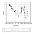
- Fig. 5 is a graph showing the relationship between the gauge factor Gf and the temperature coefficient of resistance TCR of a Cr-X alloy.
- Fig. 6 is a graph in which the horizontal axis of Fig. 5 is changed to the absolute value of the temperature coefficient of resistance TCR (unit: ppm/°C).
- Fe is an element whose behavior is significantly different from that of element M, and in particular, the change in the temperature coefficient of resistance TCR is significantly different from that of element M.
- the gauge factor Gf and the absolute value of the temperature coefficient of resistance TCR in the Cr-Fe alloy generally satisfy the following formula (a). Gf ⁇ 0.0056 ⁇
- Equation f0 shown by the dashed line in Figure 6, shows the case where the above equation (a) has an equal sign, and is a mathematical formula obtained by linear approximation using the results in Table 1 where the Fe addition amount x is 1.2 atomic % to 5.9 atomic %. Cr-Fe alloys are unable to reach the region in the upper left of the graph compared to equation f0, that is, the region where the gauge factor Gf is high and the absolute value of the temperature coefficient of resistance TCR is low.
- the Cr-Fe-M alloy according to this embodiment can achieve a range that cannot be achieved by a Cr-Fe alloy, that is, can satisfy the following formula (1).
- the Cr-Fe-M alloy according to this embodiment can, in a preferred example, reach the upper left region with the boundary line being the formula f1 shown by the solid line in Fig. 6. That is, the Cr-Fe-M alloy according to this embodiment can, in a preferred example, satisfy the following formula (2). Gf ⁇ 0.0056 ⁇
- the thickness of the strain resistor 12 of the strain gauge 10 is not limited. As shown in the examples described later, the thickness of the strain resistor 12 may have a positive correlation with the gauge factor Gf and the temperature coefficient of resistance TCR. In that case, the thickness of the strain resistor 12 can be changed to match the desired gauge factor Gf and temperature coefficient of resistance TCR. In other words, the thickness of the strain resistor 12 can be positioned as an adjustment factor for the characteristics of the strain resistor 12. The thickness of the strain resistor 12 can be adjusted in the range from a thin film of several tens of nm to a foil of several tens of ⁇ m by appropriately setting the manufacturing method.
- the method for manufacturing the strain resistor 12 according to this embodiment is not limited. As described above, since the strain resistor 12 is made of the alloy for strain resistors according to this embodiment, it can be manufactured by a known film formation method such as sputtering, or by mechanical processing such as rolling.
- an alloy having a composition corresponding to the composition of the strain resistor 12 to be manufactured may be used as the target, or a target consisting of tiled pure metals of Cr, Fe, and M may be used to adjust the composition of the strain resistor 12.
- a target consisting of tiled pure metals of Cr, Fe, and M may be used to adjust the composition of the strain resistor 12.
- two or more targets may be used for simultaneous sputtering, and the composition of the strain resistor 12 may be adjusted by adjusting the amount of power applied to each of them.
- the thickness may be preferably 300 nm or less.
- the thickness of the strain resistor 12 is too small, the resistance change due to strain may be too small and the function of the strain resistor 12 may not be properly performed.
- the thickness may be preferably 30 nm or more.
- the thin film resistor for strain gauge disclosed in Patent Document 1 is obtained by performing reactive sputtering in which oxygen molecules (O 2 ) and nitrogen molecules (N 2 ) are mixed into the atmosphere as reactive gas components, and the amount of oxygen (O) and nitrogen (N) contained in the formed film is adjusted, thereby obtaining the desired effect (gauge factor of 10 or more, resistance temperature coefficient of ⁇ 100 [ppm/° C.] or less).
- the strain resistor 12 according to this embodiment does not require adjustment of the supply amount of reactive gas components, and can be manufactured by forming an alloy film using a general-purpose sputtering device. Therefore, the strain resistor 12 according to this embodiment has excellent quality stability and excellent productivity.
- the thickness in the range of 1 ⁇ m to 10 ⁇ m, and more preferably in the range of 2 ⁇ m to 5 ⁇ m, from the viewpoints of ensuring ease of manufacturing, ease of handling, and processing accuracy of the thickness.
- the above-described embodiments are described to facilitate understanding of the present invention, and are not described to limit the present invention. Therefore, each element disclosed in the above embodiments is intended to include all design modifications and equivalents that fall within the technical scope of the present invention.
- the case where element M consists of one type of element includes the case where other elements are present to an extent that does not substantially affect the effects of the invention, and a specific example of such a case is the case where the mixture of other elements is unavoidable from the perspective of industrial production.
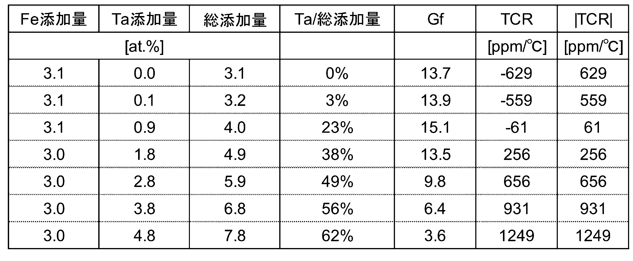
- Example 1 A strain gauge 10 was manufactured by sputtering on a substrate 30 made of a polyimide film, the substrate 30 being provided with a strain resistor 12 made of a Cr-Fe-Ta alloy.
- the composition of the Cr-Fe-Ta alloy is as shown in Table 2 (Example 1) and Table 3 (Example 2).
- the target value of the Fe additive amount x in Example 1 was 5 atomic %, and the target value of the Fe additive amount x in Example 2 was 3 atomic %.
- the thickness of the strain resistor 12 was 100 nm.
- the characteristics of the strain gauge 10 were evaluated using a sensor 100 equipped with the obtained strain gauge 10.
- the evaluation results are shown in Tables 2 and 3. Based on the results in these tables, the dependence of the gauge factor Gf on the amount of Ta added is shown in Figure 7, and the dependence of the temperature coefficient of resistance TCR on the amount of Ta added is shown in Figure 8.
- the strain gauge 10 provided in the sensor 100 produced in Examples 1 and 2.
- the gauge factor Gf exceeds 10 when the Ta addition amount y reaches 4.6 atomic % based on the trend shown in FIG. 7, and when the Ta addition amount y is 4.1 atomic % or less based on the measured values shown in Table 2.
- the temperature coefficient of resistance TCR of the strain gauge 10 is in the range of ⁇ 1000 ppm/° C. when the Ta addition amount y is 0.1 atomic % to 5.1 atomic % based on the trend shown in FIG.
- the gauge factor Gf exceeds 10 when the Ta additive amount y reaches 2.7 atomic % based on the trend shown in FIG. 7, and when the Ta additive amount y reaches 1.8 atomic % or less based on the measured values shown in Table 3.
- the temperature coefficient of resistivity TCR is in the range of ⁇ 1000 ppm/° C. when the Ta additive amount y reaches 4.0 atomic % based on the trend shown in FIG. 8, and when the Ta additive amount y reaches 3.8 atomic % or less based on the measured values shown in Table 3.
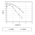
- Example 3 Using the same manufacturing method as in Example 1, sensors 100 were fabricated including strain resistors 12 made of Cr-Fe-Ta alloys having the same composition but different film thicknesses as shown in Table 4, and the characteristics of the strain gauges 10 were evaluated. The results are shown in Table 4 and Fig. 9.
- Fig. 9 is a graph showing the dependence of gauge factor Gf on temperature coefficient of resistance TCR, showing the results of Example 2 (changes in film thickness).
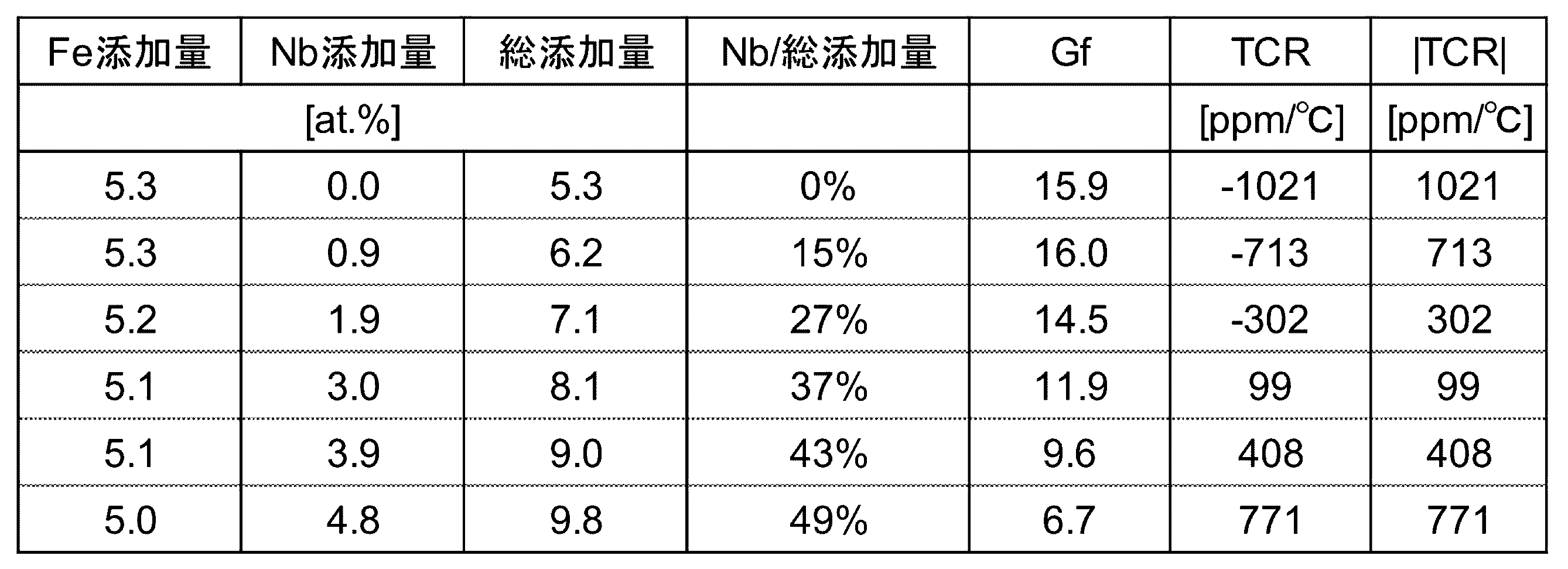
- Example 4 Strain gauges 10 were manufactured using the same manufacturing method as in Example 1, each of which was provided with a strain resistor 12 in which the type of alloy M was varied.
- Table 5 shows the case in which the alloy M was made of Nb (Example 4)
- Table 6 shows the case in which the alloy M was made of Mo (Example 5)
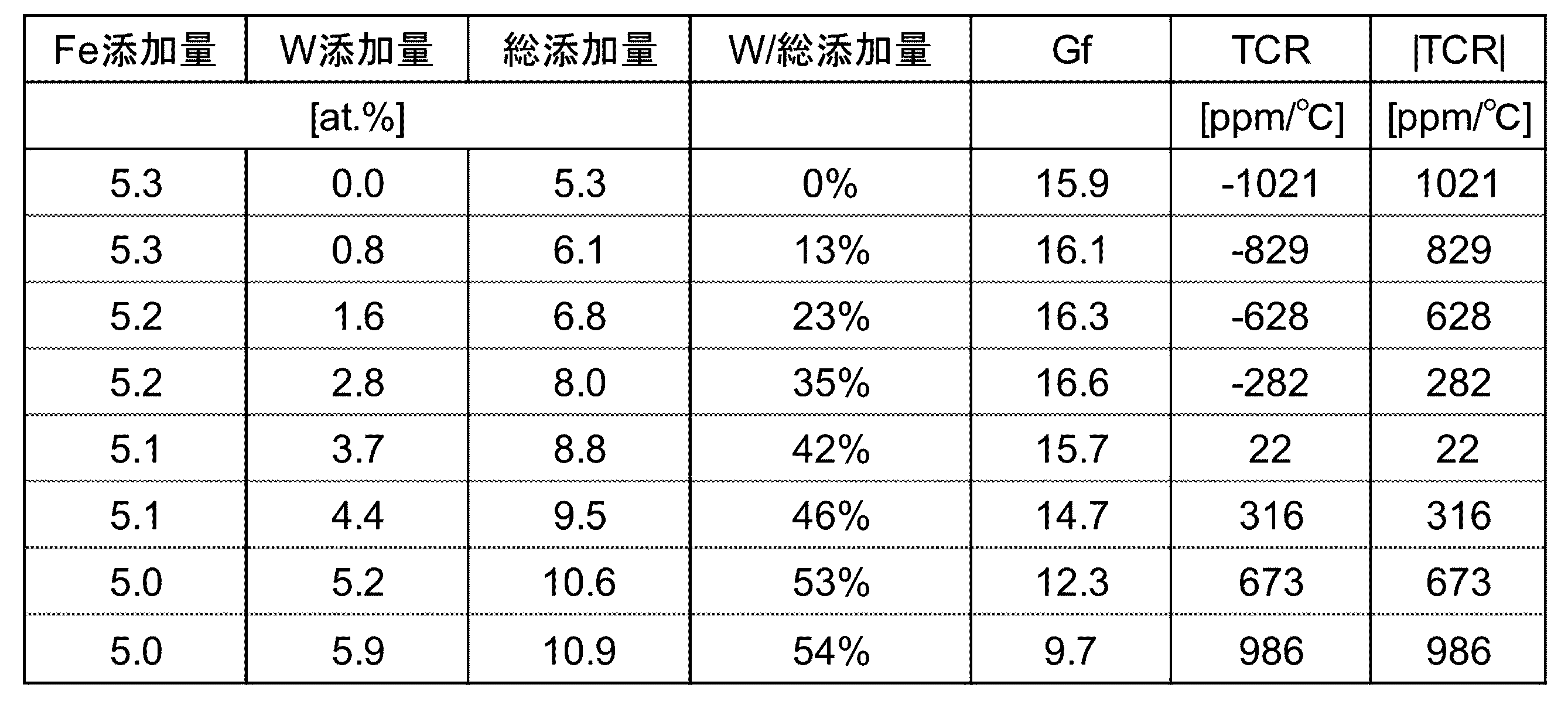
- Table 7 shows the case in which the alloy M was made of W (Example 6).
- the Fe addition amount x was aimed for 5 atomic %.
- the characteristics of the strain gauge 10 were evaluated using a sensor 100 equipped with the obtained strain gauge 10. The evaluation results are shown in Tables 5 to 7. Based on the results in these tables, the dependence of the gauge factor Gf on the amount of element M added is shown in Figure 10, and the dependence of the temperature coefficient of resistance TCR on the amount of element M added is shown in Figure 11.
- the strain gauge 10 (in which the Fe addition amount x of the Cr-Fe-M alloy constituting the strain resistor 12 is 5.0 atomic % or more and 5.3 atomic % or less) provided in the sensor 100 produced in Examples 4 to 6.
- the gauge factor Gf exceeds 10 when the amount of Nb added y reaches 3.8 atomic % based on the trend shown in FIG. 10, and reaches 3.0 atomic % or less based on the measured values shown in Table 5, and the temperature coefficient of resistance TCR is in the range of ⁇ 1000 ppm/° C. when the amount of Nb added y reaches 5.4 atomic % based on the trend shown in FIG.
- the gauge factor Gf of the strain gauge 10 exceeds 10 when the amount of Mo added y reaches 6.2 atomic % based on the trend shown in FIG. 10, and reaches 5.6 atomic % or less based on the measured values shown in Table 6, and the temperature coefficient of resistance TCR is in the range of ⁇ 1000 ppm/° C. when the amount of Mo added y reaches 5.4 atomic % based on the trend shown in FIG. Based on the trend shown in FIG. 10, the temperature coefficient of resistance TCR of the strain gauge 10 is in the range of ⁇ 1000 ppm/° C.
- the gauge factor Gf of the strain gauge 10 exceeds 10 up to the W additive amount y of 5.8 atomic % based on the trend shown in FIG. 10, and up to 5.6 atomic % based on the measured values shown in Table 7; and based on the trend shown in FIG. 11, the temperature coefficient of resistance TCR of the strain gauge 10 is in the range of ⁇ 1000 ppm/° C. up to the W additive amount y of 6.0 atomic %, and up to 0.8 atomic % to 5.9 atomic % based on the measured values shown in Table 7.
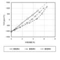
- FIG. 12 is a graph showing the results of Examples 1 and 2 (the effect of changing the composition of the Cr-Fe-Ta alloy) and the absolute value dependence of the gauge factor Gf on the temperature coefficient of resistance TCR.
- FIG. 13 is a graph showing the results of Examples 4 to 6 (type of element M) and the absolute value dependence of the gauge factor Gf on the temperature coefficient of resistance TCR. As shown in FIG. 12 and FIG. 13, it was confirmed that the results of all the Examples reached the region to the upper left of formula f0 in these figures, and further reached the region to the upper left of formula f1.
- sensor 10 strain gauge 11: laminate 12: strain resistor 13: protective layer 20: electrode 201: first electrode 202: second electrode 21: plating layer 30: substrate
Landscapes
- Chemical & Material Sciences (AREA)
- Engineering & Computer Science (AREA)
- Materials Engineering (AREA)
- Mechanical Engineering (AREA)
- Metallurgy (AREA)
- Organic Chemistry (AREA)
- Physics & Mathematics (AREA)
- General Physics & Mathematics (AREA)
- Measurement Of Length, Angles, Or The Like Using Electric Or Magnetic Means (AREA)
Abstract
ゲージ率Gfが高く温度変化の影響を受けにくい本発明の一態様に係る歪ゲージは、Cr100-x-yFexMyからなる組成を有する合金組成を有し膜状の歪抵抗体を備える歪ゲージであって、元素Mは、Nb、Mo、Ta、およびWからなる群から選ばれる1種また2種以上であり、Fe添加率であるxは0.8原子%以上11.2原子%以下であることが好ましい場合があり、M添加率であるyは0原子%超7.7原子%以下であることが好ましい場合がある。
Description
本発明は、歪抵抗体用合金、歪ゲージ、およびセンサに関する。
測定対象物(起歪体)に貼付して、測定対象物の歪みを検出する歪ゲージが知られている。歪ゲージの構成材料として、外力を受けて形状変化することに伴って抵抗が変化する歪抵抗体が例示され、具体的には、Ni、Cr、Cuなどを含有する金属系材料が用いられる。歪抵抗体は、例えば基材に膜状に形成され、フォトリソグラフィ技術およびエッチング技術などによって、ミアンダパターンなど所望のパターンに形成される。
歪抵抗体は抵抗温度係数の絶対値が大きい場合が多いため、例えば特許文献1には、歪ゲージ用抵抗体の一例として、ゲージ率が10以上であり、その抵抗温度係数は、±100[ppm/℃]以下である歪ゲージ用薄膜抵抗体として、クロム(Cr)と酸素(O)と窒素(N)を含んでおり、一般式Cr100-x-yOxNyで表され、組成比x、yは、原子%において、3.0≦x≦15.0の関係と、1.0≦y≦10.0の関係を満たしており、前記クロムが(110)配向のbcc構造を有している薄膜抵抗体が提案されている。
特許文献1に記載される薄膜抵抗体は、その製造工程に含まれる熱処理を最適化することによりクロムの配向性を整え、これにより抵抗温度係数TCRを低下させている。これはすなわち、特許文献1に記載される薄膜抵抗体は、抵抗温度係数TCRが製造工程のばらつきの影響を受けやすいことを意味している。このため、特許文献1に開示される方法では、ゲージ率Gfが高く温度変化の影響を受けにくい歪抵抗体を安定的に作ることは容易ではなかった。
本発明は、かかる事情を背景として、特許文献1とは異なるアプローチで、ゲージ率Gfが高く温度変化の影響を受けにくい歪ゲージを提供すること、また、酸素や窒素などの反応性ガス成分を製造過程で必要とせず、それゆえ汎用スパッタリング装置等を用いて、歪ゲージが備える歪抵抗体を容易に形成できるようにすることを目的とする。また、かかる歪ゲージが備える歪抵抗体を与える歪抵抗体用合金、およびかかかる歪ゲージを備えるセンサを提供することを目的とする。
上記の課題を解決するための本発明の一態様に係る歪抵抗体用合金は、Cr100-x-yFexMyからなる組成を有する歪抵抗体用合金であって、Mは、Nb、Mo、Ta、およびWからなる群から選ばれる1種または2種以上の元素(以下、「元素M」ともいう。)である。
Cr-Fe合金は、ゲージ率Gfが10以上かつ抵抗温度係数TCRが負となる歪抵抗体を与えることが可能である。一方、Cr-M合金は、ゲージ率Gfが10以上かつ抵抗温度係数TCRが正となる歪抵抗体を与えることが可能である。そこで、これらの合金であるCr100-x-yFexMyからなる組成を有する歪抵抗体用合金からなる歪抵抗体は、ゲージ率Gfが10以上であること、かつ抵抗温度係数TCRが±1000ppm/℃の範囲となることを容易に達成することができる。
しかも、合金組成によりゲージ率Gfおよび抵抗温度係数TCRを制御することができるため、特許文献1に開示されるようなCrに酸素(O)および窒素(N)を含有させる場合に比べて、結晶構造の精密な制御が必要とされない。したがって、上記の歪抵抗体用合金を用いることにより、ゲージ率Gfが高く温度の影響を受けにくい歪抵抗体を、製造負荷を高めることなく、それゆえ、高品質で、得ることが可能である。
上記の歪抵抗体用合金において、Feの添加量であるxは0.8原子%以上11.2原子%以下であることが好ましい場合がある。また、元素Mの添加量であるyは0原子%超7.7原子%以下であることが好ましい場合がある。これらの条件を満たすことにより、高品質で、ゲージ率Gfが高く温度の影響を受けにくい歪抵抗体を得ることがより安定的に実現されうる。
本発明の他の一態様は、上記の歪抵抗体用合金の合金組成を有し膜状の歪抵抗体を備える歪ゲージである。膜状の歪抵抗体は、スパッタリングなどの成膜プロセスで形成される薄膜からなるものであってもよいし、圧延などの機械加工によって形成される箔からなるものであってもよい。すなわち、「膜状」の概念は、薄膜形状および箔形状を含む。この歪ゲージは、高いゲージ率Gfを安定的に実現する観点から、前記歪抵抗体はbcc構造を有していることが好ましい。
上記の歪ゲージは、ゲージ率Gfと、抵抗温度係数TCR(単位:ppm/℃)の絶対値|TCR|とが、下記式(1)または下記式(2)を満たすことが可能であることが好ましい。
Gf>0.0056×|TCR|+10.21 (1)
Gf≧0.0056×|TCR|+11 (2)
Gf>0.0056×|TCR|+10.21 (1)
Gf≧0.0056×|TCR|+11 (2)
本発明は、別の一態様として、基材と、前記基材に設けられる上記の歪ゲージと、を備え、前記歪ゲージを検知手段とする、センサを提供する。
本発明によれば、ゲージ率Gfが高く温度変化の影響を受けにくい歪ゲージが提供される。また、かかる歪ゲージが備える歪抵抗体を与える歪抵抗体用合金、かかる歪ゲージを備えるセンサが、本発明により提供される。かかる歪ゲージが備える歪抵抗体は、汎用スパッタリング装置などを用いることにより容易に製造することが可能である。
以下、図面を参照しつつ本発明の実施形態について説明する。なお、以下の説明では、同一の部材には同一の符号を付し、一度説明した部材については適宜その説明を省略する。
図1は、本発明の一実施形態に係る歪みセンサの一例を示す図である。図1に示されるように、本実施形態に係るセンサ100は、ミアンダ形状のパターンを有する歪ゲージ10と、歪ゲージ10に通電するための電極20とを有する。歪ゲージ10および電極20は、いずれも基材30に形成されている。歪ゲージ10は検知手段として機能する。センサ100は、歪ゲージ10からの信号に基づき、歪ゲージ10の歪そのものを計測する歪センサであってもよいし、センサ100が取り付けられた部材(起歪体)の変形の程度を測定する変形・変位センサであってもよいし、起歪体の変形の程度に基づき他の物理量(圧力、速度、加速度など)を測定するセンサであってもよい。電極20の構成材料の限定されない例として、Cu、Au、およびこれらを含む合金が挙げられる。電極20は、歪ゲージ10の一方の端部に接続される第1電極201と、他方の端部に接続される第2電極202とを備え、第1電極201および第2電極202のそれぞれには、はんだ接着強度を高める目的でめっき層21が設けられている。
図2は、図1のA-A線での断面を示す概念図である。図2に示されるように、歪ゲージ10は、膜状の歪抵抗体12と、歪抵抗体12に接する部分を有して設けられた保護層13と、を含む積層体11を備え、積層体11がミアンダパターンを形成している。保護層13は必要に応じ設けられるものであって必須とされず、例えばTaによって構成されてもよい。
歪抵抗体12は、外力を受けて電流の流れる方向に長さが変化すると、抵抗値が変化する性質を有する。この性質は、下記式(A)に示されるゲージ率Gfにより定量評価することができる。
Gf=(ΔR/R)/(ΔL/L) (A)
Gf=(ΔR/R)/(ΔL/L) (A)
ここで、Lは、歪ゲージ10における外力が付与されていない状態(無負荷時)の電流の流れる方向の長さ(電流方向長さ)であり、ΔLは、歪ゲージ10に外力が付与された状態(負荷時)における無負荷時に対する歪ゲージ10の電流方向長さの変化量であり、Rは、歪ゲージ10における無負荷時の抵抗値であり、ΔRは、負荷時の無負荷時に対する歪ゲージ10の抵抗値の変化量である。
本実施形態において、歪抵抗体12は、Cr100-x-yFexMyからなる組成を有する、歪抵抗体用合金としてのCr-Fe-M合金からなる。このMは、Nb、Mo、Ta、およびWからなる元素から群から選ばれる1種または2種以上の元素(元素M)である。歪抵抗体12の結晶構造は、歪抵抗体12のゲージ率Gfを高める観点から、bcc構造であることが好ましい。歪抵抗体12の比抵抗の限定されない例示をすれば、100μΩcm以下である。
表1は、Cr-X合金(元素Xは、Fe、Ta、Nb、Mo、Wのいずれか、以下同じ。)からなる歪抵抗体12を備える歪ゲージ10について、元素Xの添加量を変化させながら、ゲージ率Gf(測定温度は25℃、以下同じ。)および抵抗温度係数TCRを測定した結果を示す表である。図3は、表1の結果から作成した、Cr-X合金からなる歪抵抗体12を備える歪ゲージ10のゲージ率Gfと元素Xの添加量との関係を示すグラフである。図4は、表1の結果から作成した、Cr-X合金からなる歪抵抗体12を備える歪ゲージ10の抵抗温度係数TCRと元素Xの添加量との関係を示すグラフである。

図3および図4に示されるように、Cr-Fe合金は、ゲージ率Gfが10以上かつ抵抗温度係数TCRが負となる歪ゲージ10を与えることが可能である。一方、Cr-Fe合金以外のCr-X合金は、ゲージ率Gfが10以上かつ抵抗温度係数TCRが正となる歪ゲージ10を与えることが可能である。そこで、これらの合金であるCr100-x-yFexMyからなる組成を有する歪抵抗体用合金からなる歪抵抗体12を備える歪ゲージ10は、ゲージ率Gfが10以上であること、かつ抵抗温度係数TCRが±1000ppm/℃の範囲となることを容易に達成することができる。
しかも、歪抵抗体12の合金組成により歪ゲージ10のゲージ率Gfおよび抵抗温度係数TCRを制御することができるため、特許文献1に開示されるようなCrに酸素(O)および窒素(N)を含有させる場合に比べて、結晶構造の精密な制御が必要とされない。それゆえ、上記の歪抵抗体用合金を用いることにより、製造負荷を高めることなく、それゆえ、高品質で、ゲージ率Gfが高く、温度の影響を受けにくい歪ゲージ10を得ることが可能である。
上記の歪抵抗体用合金において、Feの添加量であるxは0.8原子%以上11.2原子%以下であることが好ましい場合がある。図3に示されるように、Cr-Fe合金においてFe添加量xが0.8原子%以上11.2原子%以下である場合には、歪ゲージ10のゲージ率Gfが10以上となるから、Fe添加量xをこの範囲に設定することで、Cr-Fe-M合金からなる歪抵抗体12を備える歪ゲージ10においても、ゲージ率Gfが高く温度変化の影響を受けにくくすることが容易となる。ゲージ率Gfが高く温度変化の影響を受けにくい歪ゲージ10を得ることをより安定的に実現する観点から、Fe添加量xは1.2原子%以上9.3原子%以下であることが好ましい場合があり、Fe添加量xは3.1原子%以上7.6原子%以下であることがより好ましい場合がある。
また、元素Mの添加量(M添加量)であるyは0原子%超7.7原子%以下であることが好ましい場合がある。図3に示されるように、M添加量yが上記の範囲の場合には、元素Mを構成する元素のいずれかについてはゲージ率Gfが上昇傾向にあり、かつ抵抗温度係数TCRは正の値を取るため、ゲージ率Gfが高く温度変化の影響を受けにくい歪抵抗体12を得ることが容易となる。ゲージ率Gfが高く温度変化の影響を受けにくい歪抵抗体12を得ることをより安定的に実現する観点から、元素MがTaからなる場合には、M添加量yは0.5原子%以上3.5原子%以下であることが好ましいことがあり、1.1原子%以上3.1原子%以下がより好ましいことがあり、1.1原子%以上2.1原子%以下が特に好ましいことがある。
同様の観点から、元素MがNbからなる場合には、M添加量yは0.5原子%以上3.5原子%以下であることが好ましいことがあり、0.5原子%以上3.1原子%以下がより好ましいことがあり、1.1原子%以上2.0原子%以下が特に好ましいことがある。
また、同様の観点から、元素MがMoからなる場合には、M添加量yは2原子%以上14原子%以下であることが好ましいことがあり、3.3原子%以上13.5原子%以下がより好ましいことがあり、3.3原子%以上6.5原子%以下が特に好ましいことがある。
さらに、同様の観点から、元素MがWからなる場合には、M添加量yは1原子%以上12原子%以下であることが好ましいことがあり、1.2原子%以上9.1原子%以下がより好ましいことがあり、4.1原子%以上7.7原子%以下が特に好ましいことがある。
なお、Fe添加量xおよびM添加量yのいずれについても、過度に多い場合には、ゲージ率Gfが低下する傾向が見られる。ゲージ率GfはCr基材料のTn(ネール温度)に密接に関係していることが知られており、Fe、またはM添加量が過度に多い場合にはTnが適正な温度範囲から逸脱することがゲージ率Gfの低下に起因していると考えられる。したがって、Fe添加量とM添加量との総和x+yは、元素Mの構成元素の種類にも依存するが、11原子%以下であることが好ましい場合があり、10原子%以下であることがより好ましい場合があり、6原子%以下であることが特に好ましい場合がある。
また、Fe添加量xとM添加量yとの総和(x+y)に対するM添加量yの割合(y/(x+y)、単位:%)は、元素Mを構成する元素の種類にも依存するが、55%以下であることが好ましい場合があり、50%以下であることがより好ましい場合があり、40%以下であることが特に好ましい場合がある。
図5は、Cr-X合金のゲージ率Gfと抵抗温度係数TCRとの関係を示すグラフである。図6は、図5について、横軸を抵抗温度係数TCR(単位:ppm/℃)の絶対値に変更したグラフである。図5に示されるように、Cr合金の添加元素として、Feは元素Mとは挙動が大きく異なる元素であって、特に抵抗温度係数TCRの変化が元素Mとは顕著に相違している。Cr-Fe合金の特性についてより正確に確認するために、図6に示されるように横軸を抵抗温度係数TCRの絶対値に変更すると、Cr-Fe合金におけるゲージ率Gfと抵抗温度係数TCRの絶対値とは、概ね下記式(a)を満たす。
Gf≦0.0056×|TCR|+10.21 (a)
Gf≦0.0056×|TCR|+10.21 (a)
図6において破線で示した式f0は、上記式(a)が等号の場合を示しており、表1におけるFe添加量xが1.2原子%~5.9原子%の結果を用いて線形近似して得られた数式である。Cr-Fe合金は、式f0よりもグラフ中左上の領域、すなわち、ゲージ率Gfが高くて抵抗温度係数TCRの絶対値が低い領域に達することができていない。
これに対し、本実施形態に係るCr-Fe-M合金は、Cr-Fe合金では達成できない領域に達成すること、すなわち、下記式(1)を満たすことが可能である。
Gf>0.0056×|TCR|+10.21 (1)
Gf>0.0056×|TCR|+10.21 (1)
後述する実施例に示すように、本実施形態に係るCr-Fe-M合金は、好ましい一例において、図6において実線で示された式f1を境界線とする左上の領域に至ることも可能である。すなわち、本実施形態に係るCr-Fe-M合金は、好ましい一例において、下記式(2)を満たすことが可能である。
Gf≧0.0056×|TCR|+11 (2)
Gf≧0.0056×|TCR|+11 (2)
本実施形態に係る歪ゲージ10の歪抵抗体12の厚さは限定されない。後述する実施例において示すように、歪抵抗体12の厚さは、ゲージ率Gfおよび抵抗温度係数TCRに対して正の相関を有する場合がある。その場合には、求めるゲージ率Gfや抵抗温度係数TCRに合わせて、歪抵抗体12の厚さを変更すればよい。すなわち、歪抵抗体12の厚さを歪抵抗体12の特性の調整因子として位置づけることができる。歪抵抗体12の厚さは、製造方法を適切に設定することにより、数十nmの薄膜から数十μmの箔の範囲で調整することが可能である。
本実施形態に係る歪抵抗体12の製造方法は限定されない。前述のとおり、歪抵抗体12は本実施形態に係る歪抵抗体用合金からなることから、スパッタリングなどの公知の成膜方法や、圧延などの機械加工により製造することが可能である。
スパッタリングにより製造する場合には、ターゲットとして、製造する歪抵抗体12の組成に対応した組成を有する合金を用いてもよいし、CrおよびFeならびにMの純金属をタイル状に敷き詰めてなるターゲットを用いて歪抵抗体12の組成を調整してもよい。あるいは、2つ以上のターゲットを用いて同時スパッタリングを行い、各々に印加する電力量を調整して歪抵抗体12の組成を調整してもよい。なお、スパッタリングなどのドライプロセス成膜により歪抵抗体12を製造する場合には、歪抵抗体12の厚さを過大にすると、製造方法にも依存するが、内部応力が高くなりすぎて薄膜としての形状を維持できなくなることがある。歪抵抗体12の形状安定性を確保する観点から、その厚さは、300nm以下であることが好ましいことがある。一方、歪抵抗体12の厚さが過小の場合には、歪に基づく抵抗変化が過小となって歪抵抗体12としての機能を適切に発揮できないことがある。歪抵抗体12としての必須機能を果たす観点から、その厚さは、30nm以上であることが好ましい場合がある。
スパッタリングにより成膜する場合には、汎用スパッタリング装置を用いて、雰囲気としてアルゴンなどの不活性元素を用いればよい。ここで、特許文献1に開示される歪ゲージ用薄膜抵抗体は、酸素分子(O2)や窒素分子(N2)を反応性ガス成分として雰囲気に混在させ、形成した膜に含有される酸素(O)や窒素(N)の量を調整する反応性スパッタリングを行うことにより、所期の効果(ゲージ率が10以上、抵抗温度係数は、±100[ppm/℃]以下)を得るものである。ところが、反応性スパッタリングを行うためには専用の設備(マスフローコントローラなどの反応性ガス成分の供給量の制御機構)が必要であり、そのような設備を用いても、これらの元素の混在量を厳密に調整し、かつ形成した膜組成の基材上での均一性を確保することは容易ではない。これに対し、本実施形態に係る歪抵抗体12は、反応性ガス成分の供給量の調整を必要としないため、汎用スパッタリング装置を用いて合金を成膜することにより製造することが可能である。それゆえ、本実施形態に係る歪抵抗体12は、品質安定性に優れ、生産性にも優れる。
圧延などの機械加工は、量産が容易であるなど生産性の観点で有利性を有する場合がある。機械加工により歪抵抗体12を製造する場合には、製造容易性、取扱性および厚さの加工精度を確保する観点から、1μm~10μmの範囲とすることが好ましいことがあり、2μm~5μmの範囲とすることがより好ましいことがある。
以上説明した実施形態は、本発明の理解を容易にするために記載されたものであって、本発明を限定するために記載されたものではない。したがって、上記実施形態に開示された各要素は、本発明の技術的範囲に属する全ての設計変更や均等物をも含む趣旨である。例えば、元素Mが1種類の元素からなる場合とは、発明の効果に実質的に影響を与えない程度に他元素が存在する場合を含み、その場合の具体例として、工業的製造の観点から不可避的に他の元素が混在する場合が挙げられる。
以下、実施例を用いて本発明について具体的に説明する。
(実施例1および実施例2)
ポリイミドフィルムからなる基材30上に、スパッタリングにより、Cr-Fe-Ta合金からなる歪抵抗体12を備える歪ゲージ10を製造した。Cr-Fe-Ta合金の組成は表2(実施例1)および表3(実施例2)に示すとおりであり、実施例1におけるFe添加量xのねらい値は5原子%であり、実施例2におけるFe添加量xのねらい値は3原子%であった。歪抵抗体12の厚さは100nmであった。
ポリイミドフィルムからなる基材30上に、スパッタリングにより、Cr-Fe-Ta合金からなる歪抵抗体12を備える歪ゲージ10を製造した。Cr-Fe-Ta合金の組成は表2(実施例1)および表3(実施例2)に示すとおりであり、実施例1におけるFe添加量xのねらい値は5原子%であり、実施例2におけるFe添加量xのねらい値は3原子%であった。歪抵抗体12の厚さは100nmであった。

得られた歪ゲージ10を備えるセンサ100を用いて、歪ゲージ10の特性を評価した。評価結果を表2および表3に示した。また、これらの表の結果に基づき、ゲージ率GfのTa添加量依存性を図7に、抵抗温度係数TCRのTa添加量依存性を図8に示した。
実施例1および実施例2において作成したセンサ100が備える歪ゲージ10に関し、次の事項が確認された。
(1)Fe添加量xが5.1原子%以上5.3原子%以下の場合(実施例1)には、図7に示される傾向に基づくとTa添加量yが4.6原子%に至るまで、表2に示される測定値に基づくと4.1原子%以下で、ゲージ率Gfが10超となり、図8に示される傾向に基づくとTa添加量yが0.1原子%から5.1原子%まで、表2に示される測定値に基づくと0.1原子%以上4.1原子%以下で、歪ゲージ10の抵抗温度係数TCRが±1000ppm/℃の範囲となる。
(2)Fe添加量xが3.0原子%以上3.1原子%以下の場合(実施例2)には、図7に示される傾向に基づくとTa添加量yが2.7原子%に至るまで、表3に示される測定値に基づくと1.8原子%以下で、ゲージ率Gfが10超となり、図8に示される傾向に基づくとTa添加量yが4.0原子%に至るまで、表3に示される測定値に基づくと3.8原子%以下で、抵抗温度係数TCRが±1000ppm/℃の範囲となる。
(実施例3)
実施例1と同様の製造方法により、表4に示されるように、組成は等しいが膜厚が異なるCr-Fe-Ta合金からなる歪抵抗体12を備えるセンサ100を作製し、歪ゲージ10の特性を評価した。その結果を表4および図9に示す。図9は、実施例2の結果(膜厚変化)を示す、ゲージ率Gfの抵抗温度係数TCR依存性グラフである。
実施例1と同様の製造方法により、表4に示されるように、組成は等しいが膜厚が異なるCr-Fe-Ta合金からなる歪抵抗体12を備えるセンサ100を作製し、歪ゲージ10の特性を評価した。その結果を表4および図9に示す。図9は、実施例2の結果(膜厚変化)を示す、ゲージ率Gfの抵抗温度係数TCR依存性グラフである。

表4および図9に示されるように、歪抵抗体12の厚さ(膜厚)が増加すると、歪ゲージ10のゲージ率Gfおよび抵抗温度係数TCRはいずれも増加する傾向が確認された。図9中の実線は線形近似した結果であり、決定係数R2は0.97(相関係数は0.985)であった。このことから、組成を固定した場合には、歪抵抗体12の厚さを変化させることにより、歪ゲージ10のゲージ率Gfおよび抵抗温度係数TCRを調整することが可能であることが示唆された。
(実施例4から実施例6)
実施例1と同様の製造方法により、合金Mの種類を変化させた歪抵抗体12を備える歪ゲージ10を製造した。合金MがNbからなる場合(実施例4)を表5に示し、合金MがMoからなる場合(実施例5)を表6に示し、合金MがWからなる場合(実施例6)を表7に示した。なお、いずれのCr-Fe-M合金もFe添加量xは5原子%ねらいであった。
実施例1と同様の製造方法により、合金Mの種類を変化させた歪抵抗体12を備える歪ゲージ10を製造した。合金MがNbからなる場合(実施例4)を表5に示し、合金MがMoからなる場合(実施例5)を表6に示し、合金MがWからなる場合(実施例6)を表7に示した。なお、いずれのCr-Fe-M合金もFe添加量xは5原子%ねらいであった。

得られた歪ゲージ10を備えるセンサ100を用いて、歪ゲージ10の特性を評価した。評価結果を表5から表7に示した。また、これらの表の結果に基づき、ゲージ率Gfの元素M添加量依存性を図10に、抵抗温度係数TCRの元素M添加量依存性を図11に示した。
実施例4から実施例6において作成したセンサ100が備える歪ゲージ10(歪抵抗体12を構成するCr-Fe-M合金のFe添加量xは5.0原子%以上5.3原子%以下)に関し、次の事項が確認された。
(1)元素MがNbの場合(実施例4)には、図10に示される傾向に基づくとNb添加量yが3.8原子%に至るまで、表5に示される測定値に基づくと3.0原子%以下まで、ゲージ率Gfが10超となること、および図11に示される傾向に基づくとNb添加量yが5.4原子%に至るまで、表5に示される測定値に基づくと0.9原子%以上4.8原子%以下で、抵抗温度係数TCRが±1000ppm/℃の範囲となること
(2)元素MがMoの場合(実施例5)には、図10に示される傾向に基づくとMo添加量yが6.2原子%に至るまで、表6に示される測定値に基づくと5.6原子%以下で、歪ゲージ10のゲージ率Gfが10超となること、および図11に示される傾向に基づくとMo添加量yが6.2原子%に至るまで、表6に示される測定値に基づくと0.6原子%以上5.6原子%以下で、歪ゲージ10の抵抗温度係数TCRが±1000ppm/℃の範囲となること
(3)元素MがWの場合(実施例6)には、図10に示される傾向に基づくとW添加量yが5.8原子%に至るまで、表7に示される測定値に基づくと5.6原子%以下で、歪ゲージ10のゲージ率Gfが10超となること、および図11に示される傾向に基づくとW添加量yが6.0原子%に至るまで、表7に示される測定値に基づくと0.8原子%以上5.9原子%以下で、歪ゲージ10の抵抗温度係数TCRが±1000ppm/℃の範囲となること
元素Mを添加することの効果(ゲージ率Gfが高く、かつ温度変化の影響を受けにくいこと)をより明確に確認する観点から、図6に示した、ゲージ率Gfと抵抗温度係数TCRの絶対値との関係を、実施例1、実施例2および実施例4から実施例6についても確認した。図12は、実施例1および実施例2の結果(Cr-Fe-Ta合金の組成変更の影響)を示す、ゲージ率Gfの抵抗温度係数TCRの絶対値依存性グラフである。図13は、実施例4から実施例6の結果(元素Mの種類)を示す、ゲージ率Gfの抵抗温度係数TCRの絶対値依存性グラフである。図12および図13に示されるように、いずれの実施例の結果も、これらの図において式f0よりも左上の領域に至る結果を有し、さらには、式f1よりも左上の領域に至る結果を有することが確認された。
100 :センサ
10 :歪ゲージ
11 :積層体
12 :歪抵抗体
13 :保護層
20 :電極
201 :第1電極
202 :第2電極
21 :めっき層
30 :基材
10 :歪ゲージ
11 :積層体
12 :歪抵抗体
13 :保護層
20 :電極
201 :第1電極
202 :第2電極
21 :めっき層
30 :基材
Claims (8)
- Cr100-x-yFexMyからなる組成を有する歪抵抗体用合金であって、
Mは、Nb、Mo、Ta、およびWからなる群から選ばれる1種または2種以上の元素であること
を特徴とする歪抵抗体用合金。 - xは0.8原子%以上11.2原子%以下である、請求項1に記載の歪抵抗体用合金。
- yは0原子%超7.7原子%以下である、請求項1に記載の歪抵抗体用合金。
- 請求項1から請求項3のいずれかに1項に記載される歪抵抗体用合金の合金組成を有し膜状の歪抵抗体を備える歪ゲージ。
- 前記歪抵抗体はbcc構造を有する、請求項4に記載の歪ゲージ。
- ゲージ率Gfと、抵抗温度係数TCR(単位:ppm/℃)の絶対値|TCR|とが、下記式(1)を満たすことが可能である、請求項4に記載の歪ゲージ。
Gf>0.0056×|TCR|+10.21 (1) - ゲージ率Gfと、抵抗温度係数TCR(単位:ppm/℃)の絶対値|TCR|とが、下記式(2)を満たすことが可能である、請求項4に記載の歪ゲージ。
Gf≧0.0056×|TCR|+11 (2) - 基材と、請求項4から請求項7のいずれかに1項に記載され前記基材に設けられる歪ゲージと、を備え、前記歪ゲージを検知手段とする、センサ。
Priority Applications (2)
| Application Number | Priority Date | Filing Date | Title |
|---|---|---|---|
| JP2025500717A JPWO2024171663A1 (ja) | 2023-02-16 | 2024-01-11 | |
| US19/277,938 US20250347569A1 (en) | 2023-02-16 | 2025-07-23 | Alloy for strain resistors, strain gauge, and sensor |
Applications Claiming Priority (2)
| Application Number | Priority Date | Filing Date | Title |
|---|---|---|---|
| JP2023022826 | 2023-02-16 | ||
| JP2023-022826 | 2023-02-16 |
Related Child Applications (1)
| Application Number | Title | Priority Date | Filing Date |
|---|---|---|---|
| US19/277,938 Continuation US20250347569A1 (en) | 2023-02-16 | 2025-07-23 | Alloy for strain resistors, strain gauge, and sensor |
Publications (1)
| Publication Number | Publication Date |
|---|---|
| WO2024171663A1 true WO2024171663A1 (ja) | 2024-08-22 |
Family
ID=92421476
Family Applications (1)
| Application Number | Title | Priority Date | Filing Date |
|---|---|---|---|
| PCT/JP2024/000414 Ceased WO2024171663A1 (ja) | 2023-02-16 | 2024-01-11 | 歪抵抗体用合金、歪ゲージ、およびセンサ |
Country Status (3)
| Country | Link |
|---|---|
| US (1) | US20250347569A1 (ja) |
| JP (1) | JPWO2024171663A1 (ja) |
| WO (1) | WO2024171663A1 (ja) |
Citations (3)
| Publication number | Priority date | Publication date | Assignee | Title |
|---|---|---|---|---|
| JPH0995751A (ja) * | 1995-10-03 | 1997-04-08 | Res Inst Electric Magnetic Alloys | cr基合金薄膜およびその製造法ならびにストレインゲージ |
| JPH10270201A (ja) * | 1997-03-21 | 1998-10-09 | Res Inst Electric Magnetic Alloys | Cr−N基歪抵抗膜およびその製造法ならびに歪センサ |
| JP2019074454A (ja) * | 2017-10-18 | 2019-05-16 | 公益財団法人電磁材料研究所 | 熱安定性に優れ、高歪ゲージ率を有する歪センサ用薄膜合金 |
-
2024
- 2024-01-11 WO PCT/JP2024/000414 patent/WO2024171663A1/ja not_active Ceased
- 2024-01-11 JP JP2025500717A patent/JPWO2024171663A1/ja active Pending
-
2025
- 2025-07-23 US US19/277,938 patent/US20250347569A1/en active Pending
Patent Citations (3)
| Publication number | Priority date | Publication date | Assignee | Title |
|---|---|---|---|---|
| JPH0995751A (ja) * | 1995-10-03 | 1997-04-08 | Res Inst Electric Magnetic Alloys | cr基合金薄膜およびその製造法ならびにストレインゲージ |
| JPH10270201A (ja) * | 1997-03-21 | 1998-10-09 | Res Inst Electric Magnetic Alloys | Cr−N基歪抵抗膜およびその製造法ならびに歪センサ |
| JP2019074454A (ja) * | 2017-10-18 | 2019-05-16 | 公益財団法人電磁材料研究所 | 熱安定性に優れ、高歪ゲージ率を有する歪センサ用薄膜合金 |
Also Published As
| Publication number | Publication date |
|---|---|
| JPWO2024171663A1 (ja) | 2024-08-22 |
| US20250347569A1 (en) | 2025-11-13 |
Similar Documents
| Publication | Publication Date | Title |
|---|---|---|
| JP6084393B2 (ja) | 歪センサおよび歪の測定方法 | |
| US9933321B2 (en) | High gage factor strain gage | |
| US5508676A (en) | Strain gauge on a flexible support and transducer equipped with said gauge | |
| US4100524A (en) | Electrical transducer and method of making | |
| CN115516122B (zh) | 铜合金条材及其制造方法、使用铜合金条材的电阻器用电阻材料以及电阻器 | |
| WO2024171663A1 (ja) | 歪抵抗体用合金、歪ゲージ、およびセンサ | |
| JP6908554B2 (ja) | 歪抵抗膜および歪センサ、ならびにそれらの製造方法 | |
| JPH0941100A (ja) | Fe−Cr−Si基合金およびその製造法ならびにストレインゲージ | |
| WO2024171664A1 (ja) | 歪ゲージおよびセンサ | |
| JP2024054754A (ja) | 歪抵抗膜および物理量センサおよび歪抵抗膜の製造方法 | |
| JP6585679B2 (ja) | 熱安定性に優れ、高歪ゲージ率を有する歪センサ用薄膜合金 | |
| JP5408533B2 (ja) | ひずみゲージ用のFe−Ni−Cr系アイソエラスティック組成物、及び、該組成物を用いて製造されるひずみゲージ | |
| JP6840317B2 (ja) | 歪抵抗薄膜および当該歪抵抗薄膜を用いたセンサ | |
| KR101107306B1 (ko) | 압력센서용 금속 박막형 스트레인 게이지 및 이를 포함하는 압력센서 | |
| JP2019074452A (ja) | 薄膜ひずみセンサ材料および薄膜ひずみセンサ | |
| JPH0666162B2 (ja) | 歪ゲージ用薄膜抵抗体 | |
| JP4988938B2 (ja) | 感温感歪複合センサ | |
| JP6708538B2 (ja) | 熱安定性に優れた歪センサ用薄膜合金 | |
| JP2001110602A (ja) | 薄膜抵抗体形成方法及びセンサ | |
| JP7743266B2 (ja) | ひずみゲージおよびその製造方法 | |
| WO2023053606A1 (ja) | 感温感歪複合センサ | |
| JP2000331808A (ja) | 薄膜抵抗体形成方法及びこの方法により形成された薄膜抵抗体とこの薄膜抵抗体を用いた歪センサ | |
| JP5327651B2 (ja) | 電子部品用薄膜配線および薄膜配線形成用スパッタリングターゲット材 | |
| RU2750503C1 (ru) | Способ изготовления многослойной тонкопленочной гетероструктуры с заданной величиной удельного поверхностного сопротивления | |
| JP7732107B2 (ja) | 歪ゲージおよび歪センサ |
Legal Events
| Date | Code | Title | Description |
|---|---|---|---|
| 121 | Ep: the epo has been informed by wipo that ep was designated in this application |
Ref document number: 24756515 Country of ref document: EP Kind code of ref document: A1 |
|
| WWE | Wipo information: entry into national phase |
Ref document number: 2025500717 Country of ref document: JP |
|
| NENP | Non-entry into the national phase |
Ref country code: DE |
|
| 122 | Ep: pct application non-entry in european phase |
Ref document number: 24756515 Country of ref document: EP Kind code of ref document: A1 |