WO2024252619A1 - Procédé de réglage d'itinéraire pour câble de pose - Google Patents
Procédé de réglage d'itinéraire pour câble de pose Download PDFInfo
- Publication number
- WO2024252619A1 WO2024252619A1 PCT/JP2023/021358 JP2023021358W WO2024252619A1 WO 2024252619 A1 WO2024252619 A1 WO 2024252619A1 JP 2023021358 W JP2023021358 W JP 2023021358W WO 2024252619 A1 WO2024252619 A1 WO 2024252619A1
- Authority
- WO
- WIPO (PCT)
- Prior art keywords
- pipeline
- sensor
- route
- continuity
- conduit
- Prior art date
- Legal status (The legal status is an assumption and is not a legal conclusion. Google has not performed a legal analysis and makes no representation as to the accuracy of the status listed.)
- Ceased
Links
Images


Classifications
-
- E—FIXED CONSTRUCTIONS
- E03—WATER SUPPLY; SEWERAGE
- E03F—SEWERS; CESSPOOLS
- E03F7/00—Other installations or implements for operating sewer systems, e.g. for preventing or indicating stoppage; Emptying cesspools
-
- G—PHYSICS
- G01—MEASURING; TESTING
- G01N—INVESTIGATING OR ANALYSING MATERIALS BY DETERMINING THEIR CHEMICAL OR PHYSICAL PROPERTIES
- G01N22/00—Investigating or analysing materials by the use of microwaves or radio waves, i.e. electromagnetic waves with a wavelength of one millimetre or more
Definitions
- This disclosure relates to technology for laying cables in underground conduits.
- Optical fiber cables are generally installed using utility poles or conduits, and are provided from station buildings to individual homes.
- the route of the conduit to be used from the starting point to the destination is set in advance.
- Non-Patent Document 1 Previously, pipe cameras were used to check for abnormalities in pipes to check the state of continuity (see, for example, Non-Patent Document 1).
- Non-Patent Document 1 requires the insertion of a pipe camera into the conduit through a manhole, so it is carried out when the cable is laid. As a result, if continuity is lost, the route of the conduit must be changed at the cable laying site, which reduces the efficiency of the cable laying work.
- the purpose of this disclosure is to make it possible to determine the continuity state of underground pipelines without having to work in manholes.
- the system of the present disclosure comprises: A sensor that is installed in a pipeline buried underground and detects a continuity state of the pipeline; A database for managing detection results obtained by the sensor; and Equipped with.
- the system of the present disclosure may include a calculation device.
- the calculation device executes the cable laying route setting method of the present disclosure.
- the calculation device sets the route of the conduit along which the cable is laid based on the detection results stored in the database.
- the calculation device sets the route of the conduit along which the cable is laid based on the detection results obtained by a sensor that detects the conduit's electrical conduit state.
- the sensor may detect the continuity of the pipeline using radio waves or sound waves.
- the sensor may also be installed in a manhole that connects the pipeline to the ground.
- FIG. 1 illustrates an example embodiment of a system of the present disclosure.
- 1 illustrates an example embodiment of a system of the present disclosure.
- 13 shows an example of a flow for setting a laying route.
- FIG. 2 is an explanatory diagram for setting a route connecting a departure point and a destination. 13 shows an example of a flow for setting a laying route.
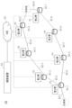
- First Embodiment 1 shows an example of a system configuration of the present disclosure.
- the system of the present embodiment includes one or more sensors 91 and a database 92.
- the database 92 is any device capable of collecting information from the sensor 91, and may be composed of one or more devices.
- the sensor 91 is a device that is installed in a pipeline 82 buried underground and detects the continuity state of the pipeline 82. Multiple sensors 91 may be installed in one pipeline 82.
- the database 92 manages the detection results obtained by the sensor 91.
- the sensor 91 has a function of detecting the continuity state of the pipeline 82 and determining whether the pipeline 82 is conductive. For example, a radio wave is transmitted from the sensor 91 installed in the manhole 81-1, and is received by the sensor 91 installed in the manhole 81-2. The sensor 91 installed in the manhole 81-2 then determines whether the pipeline 82 is conductive or not due to the presence of an obstacle 70 such as soil, based on the radio wave that has passed through the pipeline 82. Therefore, by storing the results of the determination of continuity/non-continuity in the database 92, the information on the continuity/non-continuity of the pipeline 82 can be managed for each pipeline 82. Therefore, this embodiment makes it possible to grasp the continuity state of the pipeline 82 buried underground without performing work in the manholes 81-1 and 81-2.
- the present disclosure is not limited to this.
- the sensor 91 may transmit the received power to the database 92, and the database 92 may store the received power.
- a separately provided computing device may determine the continuity of the pipe 82 based on the received power.
- the information transmitted by the sensor 91 may be any information capable of determining the continuity of the pipe 82, such as the received power.
- the sensor 91 may also receive radio waves reflected by the pipeline 82.
- the sensors 91 installed in the manholes 81-1 and 81-2 may transmit radio waves to the pipeline 82 and receive the radio waves reflected by the pipeline 82. This makes it possible to detect the obstacle 70 from both sides of the pipeline 82 and identify the location of the blockage in the pipeline 82.
- the present disclosure is not limited to radio waves, and any parameter that propagates through the space inside the pipe 82 and can be detected by the sensor 91, such as sound waves, light, or wind force, can be used. Also, a camera may be installed in the pipe 82.
- the sensor 91 is placed at any position depending on the method for detecting the continuity of the pipeline 82.
- the sensor 91 may be placed in each manhole 81 located at both ends of the pipeline 82, or may be placed inside the pipeline 82.
- the sensor 91 may be placed either inside or outside the manhole 81 as long as it is possible to determine the continuity.
- Second Embodiment 2 shows an example of a system configuration according to the present disclosure.
- the system according to the present embodiment includes a plurality of sensors 91, a database 92 that collects information from the sensors 91, a calculation device 93 that sets a route for a pipeline 82 using the information from the database 92, and a display device 95 that displays a determination result of the calculation device 93.
- the display device 95 may be provided in the calculation device 93.
- the sensor 91 is installed for each pipeline 82 and is a device for determining the continuity of the pipeline 82.
- a plurality of sensors 91 may be installed in one pipeline 82.
- the database 92 is a device that stores the continuity determination results of each of the pipelines 82, and may be composed of one or more devices.
- the computing device 93 is a device having a route calculation function for calculating a laying route from a starting point to a destination.
- the computing device 93 may have a route setting function for setting the laying route obtained by calculation.
- the sensor 91 determines the continuity of the pipeline 82 and transmits the determination result to the database 92.
- the means for transmitting the determination result may be wired or wireless.
- the database 92 acquires and stores the determination results from each sensor 91. In this way, the continuity determination results of each pipeline 82 are collected in the database 92.
- the calculation device 93 uses the continuity determination results of each pipeline 82 stored in the database 92 to extract pipelines 82 that are capable of continuity, and calculates the installation route from the starting point to the destination.
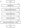
- FIG. 3 shows an example of a cable installation route setting method executed by the computing device 93.
- conduit information is read from the database 92.
- information such as manhole positions and the conduit length between manholes is read for each candidate route of the conduit 82 along which the cable is laid.
- step S12 the continuity determination results of each pipeline 82 are read from the database 92.
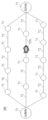
- the continuity determination results of each pipeline 82 collected from the sensor 91 are read. This allows the calculation device 93 to create a connection configuration diagram as shown in FIG. 4, in which the starting point, destination, and manhole 81 are set as nodes 71, and the pipelines 82 are set as edges 72.
- the pipe 82 determined to be non-conductive is removed. For example, as shown in Fig. 4, the edge 72N corresponding to the pipe 82 determined to be non-conductive is removed.
- step S13 which preliminarily excludes pipelines 82 that are determined to be non-conductive by the sensor 91, making it possible to set a laying route that uses only pipelines 82 that are conductive.
- step S14 a starting point and a destination are set.
- a starting point and a destination where a cable is to be laid are set.
- step S15 a route connecting the departure point and the destination is calculated.
- a combination of pipelines 82 connecting the departure point and the destination is calculated using an algorithm for solving the shortest route problem, such as Dijkstra's algorithm.
- the departure point, the destination, and the manholes 81 are set as nodes 71, the pipelines 82 are set as edges 72, and the pipeline length is set as a weight to calculate the shortest route.
- step S15 the calculation may be performed so as to minimize the total weight (pipe length), or so as to minimize the number of nodes (manholes) passed through. Other factors may also be taken into consideration, such as increasing the weight of pipes 82 in areas with a high risk on the hazard map or liquefaction map.
- this embodiment is equipped with a sensor 91 for determining the continuity of the pipelines 82, and based on the results of the continuity determination for each pipeline 82, it is possible to extract pipelines 82 that are capable of continuity, avoid pipelines that are highly likely to be non-conductive, and automatically calculate the installation route to the destination.
- sensors 91 are installed in all manholes 81, but sensors 91 do not have to be installed in all manholes 81.
- Third Embodiment 5 shows an example of a flow for calculating a cable laying route in the calculation device 93.
- steps S23 and S25 are executed instead of steps S13 and S15 in the second embodiment.
- step S23 a conductivity is set for each conduit 82.
- the conductivity is the proportion of conduction in the conduit 82. In other words, the higher the conductivity, the higher the probability that the cable can be laid, and the lower the conductivity, the higher the probability that the cable cannot be laid.
- the conductivity rate may be calculated using information obtained by the sensor 91.
- the conductivity rate is the ratio of the received power detected by the sensor 91-2 to the received power that can be detected by the sensor 91-2 when nothing is placed in the pipeline 82.
- step S25 the shortest route connecting the departure point and the destination is calculated based on the conductivity rate of each pipeline 82.
- the priority of an edge 72 that is more likely to be non-conductive is lowered.
- the calculation device 93 performs calculations that reflect the fact that the lower the conductivity rate, the greater the weight and number of nodes.
- the route of the pipeline 82 is calculated taking into account the probability of non-conduction, making it possible to set a more appropriate installation route.
- the arithmetic device 93 of the present invention can also be realized by a computer and a program, and the program can be recorded on a recording medium or provided via a network.
- the program of the present disclosure is a program for causing a computer to realize each function of the arithmetic device 93 according to the present disclosure, and is a program for causing a computer to execute each procedure of the method executed by the arithmetic device 93 according to the present disclosure.
Landscapes
- Life Sciences & Earth Sciences (AREA)
- Physics & Mathematics (AREA)
- Health & Medical Sciences (AREA)
- General Physics & Mathematics (AREA)
- Chemical & Material Sciences (AREA)
- Analytical Chemistry (AREA)
- Biochemistry (AREA)
- General Health & Medical Sciences (AREA)
- Electromagnetism (AREA)
- Immunology (AREA)
- Pathology (AREA)
- Engineering & Computer Science (AREA)
- Hydrology & Water Resources (AREA)
- Public Health (AREA)
- Water Supply & Treatment (AREA)
- Laying Of Electric Cables Or Lines Outside (AREA)
Abstract
La présente divulgation concerne un système comprenant : des capteurs qui sont installés dans un pipeline enterré sous terre et détectent l'état de conduction du pipeline ; et une base de données qui gère les résultats de détection obtenus par les capteurs.
Priority Applications (1)
| Application Number | Priority Date | Filing Date | Title |
|---|---|---|---|
| PCT/JP2023/021358 WO2024252619A1 (fr) | 2023-06-08 | 2023-06-08 | Procédé de réglage d'itinéraire pour câble de pose |
Applications Claiming Priority (1)
| Application Number | Priority Date | Filing Date | Title |
|---|---|---|---|
| PCT/JP2023/021358 WO2024252619A1 (fr) | 2023-06-08 | 2023-06-08 | Procédé de réglage d'itinéraire pour câble de pose |
Publications (1)
| Publication Number | Publication Date |
|---|---|
| WO2024252619A1 true WO2024252619A1 (fr) | 2024-12-12 |
Family
ID=93795625
Family Applications (1)
| Application Number | Title | Priority Date | Filing Date |
|---|---|---|---|
| PCT/JP2023/021358 Ceased WO2024252619A1 (fr) | 2023-06-08 | 2023-06-08 | Procédé de réglage d'itinéraire pour câble de pose |
Country Status (1)
| Country | Link |
|---|---|
| WO (1) | WO2024252619A1 (fr) |
Citations (2)
| Publication number | Priority date | Publication date | Assignee | Title |
|---|---|---|---|---|
| JP2003224911A (ja) * | 2001-11-22 | 2003-08-08 | Sanki Eng Co Ltd | 情報対応管の構築方法およびその構築構造ならびにその構築部材 |
| JP2017008529A (ja) * | 2015-06-19 | 2017-01-12 | 株式会社日立製作所 | 水道の管網管理システム |
-
2023
- 2023-06-08 WO PCT/JP2023/021358 patent/WO2024252619A1/fr not_active Ceased
Patent Citations (2)
| Publication number | Priority date | Publication date | Assignee | Title |
|---|---|---|---|---|
| JP2003224911A (ja) * | 2001-11-22 | 2003-08-08 | Sanki Eng Co Ltd | 情報対応管の構築方法およびその構築構造ならびにその構築部材 |
| JP2017008529A (ja) * | 2015-06-19 | 2017-01-12 | 株式会社日立製作所 | 水道の管網管理システム |
Similar Documents
| Publication | Publication Date | Title |
|---|---|---|
| US11506562B2 (en) | Monitoring of fluid pipes | |
| KR100814642B1 (ko) | 지중매설 관로 탐지 시스템 | |
| US8988969B2 (en) | Detection of cross bores involving buried utilities | |
| CN111006849A (zh) | 一种判断油气管道伴行光缆敷设状态的方法及系统 | |
| WO2011118947A2 (fr) | Système de gestion de réseaux d'alimentation souterrains et procédé de traitement d'informations correspondant | |
| KR102805254B1 (ko) | 상수도 시설물 데이터 수집 및 구축 방법 | |
| CN120726773A (zh) | 一种基于分布式光纤技术的边坡大变形及时感知与分级告警方法 | |
| CN111965693A (zh) | 一种基于光缆的管线走向示踪方法及系统 | |
| CN111049574A (zh) | 一种光缆中断位置快速定位的方法及系统 | |
| WO2024252619A1 (fr) | Procédé de réglage d'itinéraire pour câble de pose | |
| CN115061211B (zh) | 一种城网地埋电缆路径图校正方法及系统 | |
| JP2003058588A (ja) | 通信用管路設定管理方法およびシステムと通信用管路設定管理プログラムを記録した記録媒体と通信用管路保守管理方法およびシステムと通信用管路保守管理プログラムを記録した記録媒体および通信用管路管理システム | |
| CN115150260B (zh) | 通信线缆监测方法、装置、系统、电子设备及存储介质 | |
| JP2003234708A (ja) | 下水道光ネットワークシステム | |
| JP5723395B2 (ja) | 地震災害対策の優先順位決定装置及び方法 | |
| CN118036845A (zh) | 一种电缆管道铺设线路规划的方法及系统 | |
| KR101071562B1 (ko) | 장거리 케이블 포설 공법 | |
| Vaseli | Application of micro-trenching for fiber to the home | |
| Madryas et al. | Inspection of pipes as an element of operating municipal sewerage networks | |
| WO2024252617A1 (fr) | Système d'inspection de continuité pour pipeline enterré souterrain | |
| WO2024252618A1 (fr) | Système d'inspection de continuité pour pipeline enterré souterrain | |
| CN110174142A (zh) | 一种电缆排管的嵌入式智能监测装置 | |
| WO2024252621A1 (fr) | Procédé d'inspection pour pipeline enterré souterrain | |
| CN102760528A (zh) | 一种带通讯与温度监测的多功能电缆 | |
| US7096225B2 (en) | Communication conduit setting managing method, system thereof, storing medium storing communication conduit setting managing program, communication conduit maintenance managing method, system thereof, storing medium storing communication conduit maintenance managing program, and communication conduit managing system |
Legal Events
| Date | Code | Title | Description |
|---|---|---|---|
| 121 | Ep: the epo has been informed by wipo that ep was designated in this application |
Ref document number: 23940717 Country of ref document: EP Kind code of ref document: A1 |
|
| NENP | Non-entry into the national phase |
Ref country code: DE |