EP0078658A2 - Verfahren zum Formen von Glasformlingen - Google Patents
Verfahren zum Formen von Glasformlingen Download PDFInfo
- Publication number
- EP0078658A2 EP0078658A2 EP82305700A EP82305700A EP0078658A2 EP 0078658 A2 EP0078658 A2 EP 0078658A2 EP 82305700 A EP82305700 A EP 82305700A EP 82305700 A EP82305700 A EP 82305700A EP 0078658 A2 EP0078658 A2 EP 0078658A2
- Authority
- EP
- European Patent Office
- Prior art keywords
- mould
- glass
- preform
- temperature
- poises
- Prior art date
- Legal status (The legal status is an assumption and is not a legal conclusion. Google has not performed a legal analysis and makes no representation as to the accuracy of the status listed.)
- Granted
Links
Images
Classifications
-
- C—CHEMISTRY; METALLURGY
- C03—GLASS; MINERAL OR SLAG WOOL
- C03B—MANUFACTURE, SHAPING, OR SUPPLEMENTARY PROCESSES
- C03B11/00—Pressing molten glass or performed glass reheated to equivalent low viscosity without blowing
- C03B11/06—Construction of plunger or mould
- C03B11/08—Construction of plunger or mould for making solid articles, e.g. lenses
-
- C—CHEMISTRY; METALLURGY
- C03—GLASS; MINERAL OR SLAG WOOL
- C03B—MANUFACTURE, SHAPING, OR SUPPLEMENTARY PROCESSES
- C03B11/00—Pressing molten glass or performed glass reheated to equivalent low viscosity without blowing
-
- C—CHEMISTRY; METALLURGY
- C03—GLASS; MINERAL OR SLAG WOOL
- C03C—CHEMICAL COMPOSITION OF GLASSES, GLAZES OR VITREOUS ENAMELS; SURFACE TREATMENT OF GLASS; SURFACE TREATMENT OF FIBRES OR FILAMENTS MADE FROM GLASS, MINERALS OR SLAGS; JOINING GLASS TO GLASS OR OTHER MATERIALS
- C03C3/00—Glass compositions
- C03C3/04—Glass compositions containing silica
- C03C3/062—Glass compositions containing silica with less than 40% silica by weight
- C03C3/07—Glass compositions containing silica with less than 40% silica by weight containing lead
- C03C3/072—Glass compositions containing silica with less than 40% silica by weight containing lead containing boron
-
- C—CHEMISTRY; METALLURGY
- C03—GLASS; MINERAL OR SLAG WOOL
- C03C—CHEMICAL COMPOSITION OF GLASSES, GLAZES OR VITREOUS ENAMELS; SURFACE TREATMENT OF GLASS; SURFACE TREATMENT OF FIBRES OR FILAMENTS MADE FROM GLASS, MINERALS OR SLAGS; JOINING GLASS TO GLASS OR OTHER MATERIALS
- C03C3/00—Glass compositions
- C03C3/04—Glass compositions containing silica
- C03C3/076—Glass compositions containing silica with 40% to 90% silica, by weight
- C03C3/089—Glass compositions containing silica with 40% to 90% silica, by weight containing boron
- C03C3/091—Glass compositions containing silica with 40% to 90% silica, by weight containing boron containing aluminium
-
- C—CHEMISTRY; METALLURGY
- C03—GLASS; MINERAL OR SLAG WOOL
- C03C—CHEMICAL COMPOSITION OF GLASSES, GLAZES OR VITREOUS ENAMELS; SURFACE TREATMENT OF GLASS; SURFACE TREATMENT OF FIBRES OR FILAMENTS MADE FROM GLASS, MINERALS OR SLAGS; JOINING GLASS TO GLASS OR OTHER MATERIALS
- C03C3/00—Glass compositions
- C03C3/04—Glass compositions containing silica
- C03C3/076—Glass compositions containing silica with 40% to 90% silica, by weight
- C03C3/102—Glass compositions containing silica with 40% to 90% silica, by weight containing lead
- C03C3/108—Glass compositions containing silica with 40% to 90% silica, by weight containing lead containing boron
-
- C—CHEMISTRY; METALLURGY
- C03—GLASS; MINERAL OR SLAG WOOL
- C03C—CHEMICAL COMPOSITION OF GLASSES, GLAZES OR VITREOUS ENAMELS; SURFACE TREATMENT OF GLASS; SURFACE TREATMENT OF FIBRES OR FILAMENTS MADE FROM GLASS, MINERALS OR SLAGS; JOINING GLASS TO GLASS OR OTHER MATERIALS
- C03C3/00—Glass compositions
- C03C3/12—Silica-free oxide glass compositions
- C03C3/23—Silica-free oxide glass compositions containing halogen and at least one oxide, e.g. oxide of boron
- C03C3/247—Silica-free oxide glass compositions containing halogen and at least one oxide, e.g. oxide of boron containing fluorine and phosphorus
-
- B—PERFORMING OPERATIONS; TRANSPORTING
- B29—WORKING OF PLASTICS; WORKING OF SUBSTANCES IN A PLASTIC STATE IN GENERAL
- B29C—SHAPING OR JOINING OF PLASTICS; SHAPING OF MATERIAL IN A PLASTIC STATE, NOT OTHERWISE PROVIDED FOR; AFTER-TREATMENT OF THE SHAPED PRODUCTS, e.g. REPAIRING
- B29C43/00—Compression moulding, i.e. applying external pressure to flow the moulding material; Apparatus therefor
- B29C43/32—Component parts, details or accessories; Auxiliary operations
- B29C43/36—Moulds for making articles of definite length, i.e. discrete articles
- B29C43/361—Moulds for making articles of definite length, i.e. discrete articles with pressing members independently movable of the parts for opening or closing the mould, e.g. movable pistons
- B29C2043/3615—Forming elements, e.g. mandrels or rams or stampers or pistons or plungers or punching devices
- B29C2043/3618—Forming elements, e.g. mandrels or rams or stampers or pistons or plungers or punching devices plurality of counteracting elements
-
- B—PERFORMING OPERATIONS; TRANSPORTING
- B29—WORKING OF PLASTICS; WORKING OF SUBSTANCES IN A PLASTIC STATE IN GENERAL
- B29C—SHAPING OR JOINING OF PLASTICS; SHAPING OF MATERIAL IN A PLASTIC STATE, NOT OTHERWISE PROVIDED FOR; AFTER-TREATMENT OF THE SHAPED PRODUCTS, e.g. REPAIRING
- B29C43/00—Compression moulding, i.e. applying external pressure to flow the moulding material; Apparatus therefor
- B29C43/02—Compression moulding, i.e. applying external pressure to flow the moulding material; Apparatus therefor of articles of definite length, i.e. discrete articles
- B29C43/021—Compression moulding, i.e. applying external pressure to flow the moulding material; Apparatus therefor of articles of definite length, i.e. discrete articles characterised by the shape of the surface
-
- B—PERFORMING OPERATIONS; TRANSPORTING
- B29—WORKING OF PLASTICS; WORKING OF SUBSTANCES IN A PLASTIC STATE IN GENERAL
- B29C—SHAPING OR JOINING OF PLASTICS; SHAPING OF MATERIAL IN A PLASTIC STATE, NOT OTHERWISE PROVIDED FOR; AFTER-TREATMENT OF THE SHAPED PRODUCTS, e.g. REPAIRING
- B29C43/00—Compression moulding, i.e. applying external pressure to flow the moulding material; Apparatus therefor
- B29C43/32—Component parts, details or accessories; Auxiliary operations
- B29C43/36—Moulds for making articles of definite length, i.e. discrete articles
- B29C43/3642—Bags, bleeder sheets or cauls for isostatic pressing
-
- B—PERFORMING OPERATIONS; TRANSPORTING
- B29—WORKING OF PLASTICS; WORKING OF SUBSTANCES IN A PLASTIC STATE IN GENERAL
- B29L—INDEXING SCHEME ASSOCIATED WITH SUBCLASS B29C, RELATING TO PARTICULAR ARTICLES
- B29L2011/00—Optical elements, e.g. lenses, prisms
- B29L2011/0016—Lenses
-
- C—CHEMISTRY; METALLURGY
- C03—GLASS; MINERAL OR SLAG WOOL
- C03B—MANUFACTURE, SHAPING, OR SUPPLEMENTARY PROCESSES
- C03B2215/00—Press-moulding glass
- C03B2215/72—Barrel presses or equivalent, e.g. of the ring mould type
Definitions
- Precision optical elements require highly polished surfaces of exacting figure and surface quality.
- the surfaces demand fabrication in proper geometric relation to each other and, where the elements are to be used in transmission applications, they will be prepared from a material of controlled, uniform, and isotropic refractive index.
- Precision optical elements of glass are customarily produced via one of two complex, multistep processes.
- a glass batch is melted in a conventional manner and the melt formed into a glass body having a controlled and homogeneous refractive index.
- the body may be reformed utilizing well-known repressing techniques to yield a shape approximating the desired final article.
- the surface figure and finish of the body at this stage of production are not adequate for image forming optics.
- the rough article is fine annealed to develop the proper refractive index and the surface figure improved via conventional grinding practices.
- the glass melt is formed into a bulk body which is immediately fine annealed and subsequently cut and ground to articles of a desired configuration.
- United States Patent No. 2,410,616 describes an apparatus and method for moulding glass lenses.
- the moulds are capable of being heated and the temperatures thereof controlled within narrow ranges compatible with the glasses being moulded.
- An inert or reducing gas environment preferably hydrogen
- the principal inventive disclosure in that patent involves the use of a flame curtain (normally burning hydrogen) over the opening of a chamber enclosing the moulds to prevent the entrance of air thereinto. No working example specifically illustrating moulding process parameters is provided.
- United States Patent No. 3,833,347 is also directed to an apparatus and method for press moulding glass lenses. Again, the moulds are capable of being heated and the temperature thereof closely controlled. An inert gas surrounds the moulds to preclude oxidation thereof.
- the inventive disclosure contemplates the use of mould surfaces composed of glasslike carbon. The use of metal dies was stated to produce lens surfaces which are not suitable for photographic applications.
- the method involves eight steps: (1) a chunk of glass is placed into a mould; (2) a chamber surrounding the mould is first evacuated and then a reducing gas is introduced therein; (3) the mould temperature is raised to about the softening point of the glass; (4) a load is applied to the mould to shape the glass; (5) the temperature of the mould is reduced to below the transformation range of the glass, while maintaining the load on the mould to prevent distortion of the shaped glass body; (6) the load is removed; (7) the mould is further cooled to about 300°C to inhibit oxidation of the glasslike carbon; and, (8) the mould is opened. Glass lenses so produced were asserted to be essentially strain free such that no further annealing was necessary.
- United States Patent No. 3,844,755 is directed to an apparatus and method for transfer moulding glass lenses.
- the method contemplates eight steps: (1) placing a gob of optical glass in a transfer chamber fabricated from glasslike carbon; (2) heating the chamber to first evacuate the air therefrom and then introducing a reducing gas therein; (3) heating the chamber to about the softening point of the glass; (4) applying a load to the softened glass to cause it to flow through sprues into mould cavities defined by glasslike carbon surfaces which shape the glass; (5) reducing the temperature of the chamber to below the transformation temperature of the glass, while maintaining the load to prevent distortion of the shaped glass body; (6) removing the load; (7) further cooling the chamber to about 300°C to inhibit oxidation of the glasslike carbon; and, (8) opening the mould.
- United States Patent No. 3,900,328 provides a general description of moulding glass lenses utilizing moulds fabricated from glasslike carbon.
- the patent discloses placing a portion of heat-softened glass into the cavity of a mould prepared from glasslike carbon, applying appropriate amounts of heat and pressure to the mould, while maintaining a non-oxidizing atmosphere in the vicinity of the mould, cooling and opening the mould, and then removing the finished lens therefrom.
- United States Patent No. 4,073,654 is concerned with the press forming of optical lenses from hydrated glass.
- the process comprehends placing granules of hydrated glass into a mould, drawing a vacuum on the mould, heating the mould to a sufficiently high temperature to sinter the granules into an integral shape while the mould is sealed to prevent escape of water vapour therefrom, applying a load to the mould, releasing the load from the mould and opening the mould.
- Suggested mould materials included glasslike carbon, tungsten carbide, and alloys of tungsten.
- United States Patent No. 4,139,677 describes press forming and transfer moulding of glass lenses simulating the method of Patent No. 3,833,347 and 3,844,755 above, but utilizing silicon carbide or silicon nitride as the glass contacting material of the moulds, rather than glasslike carbon.
- European Patent Application 19342 discloses the isothermal pressing of glass lenses at temperatures above the softening points of the glasses, i.e., at temperatures where the glasses exhibit viscosities of less than 10 7.6 poises (10 ' Pa.s). There is no discussion of the manner in which the pressed lenses are cooled to room temperature so it must be assumed that the "conventional" practice was utilized.
- the prior art relating to the isothermal pressing of glass lenses has generally involved pressing at temperatures at or above the softening point of the glass with annealing of the lenses under load within the mould. It is quite apparent that, by its very nature, the process is slow, i.e. the pressing cycle involving the time required for inserting the glass into the mould, pressing, annealing in the mould, and removal of the lens from the mould is undesirably long.
- the present invention is an improvement upon the known process for isothermally pressing glass objects which improvement is capable of yielding shapes of exceedingly high precision and reproducibility, provides press cycling times of much shorter duration, and permits the use of a wide range of mould materials.
- the inventive method comprises seven general steps:
- the nature of the mould material is not critical; it must be capable of accepting a good surface finish, be substantially inert to the glass, and have sufficient rigidity to retain the surface figure at pressing temperatures.
- problems of replicating detrimental features of the mould surface such as the crystal structure of metal moulds, have not been encountered in the process of the present invention.
- mould surface materials are available. Those which can be used include several 400 series stainless steels, electroless nickel, beryllium nickel alloys,tungsten carbide, alloys of noble metals such as platinum, rhodium, and gold, and fused silica. Glasslike carbon, silicon carbide, and silicon nitride moulds are also operable but the present process does not require the use of such expensive materials.
- the mould surfaces may be in the form of either bulk material or coatings on an appropriate substrate.
- a body of optical quality glass may be prepared through melting a batch therefor in a conventional manner.
- the weight of the glass body must be closely controlled, the weight range being determined by the design of the article to be moulded.
- the shape of the body is fashioned to minimize inclusion of optical inhomogeneities.
- the glass body is shaped to minimize trapping of gas in the mould cavities.
- the glass body should have a curve sharper than that of the mould cavity so that it will contact the centre of the mould cavity first.
- gas trapping can also be avoided via the traditional method of venting the mould, but this procedure generally leads to the development of defects on the optical surface.
- the geometry of the glass body or preform will match the configuration of the mould as closely as possible. Such close matching results in the fastest, most balanced pressing, and provides a means for preventing the development of fins on the final article.
- the glass preform will exhibit little surface roughness. The moulding process will improve the surface finish of the glass body, but excessive roughness can lead to surface inclusions and optical inhomogeneities.
- the moulding operation of the invention will involve an ostensibly isothermal condition during the period wherein the final figure of the shaped article is being formed.
- isothermal means that the temperature of the mould and that of the glass preform, at least in the vicinity of the mould, are approximately identical. The temperature differences permitted are dependent upon the overall size and specific design of the final glass shape, but the difference will, preferably, be less than 20°C and, most desirably, less than 10°C.
- This isothermal condition will be maintained for a period of sufficient length to allow the pressure on the moulds to force the glass preform to flow into conformity with the surface of the mould.
- the glass products moulded in accordance with the inventive process contain too much thermal stress to be suitable for immediate use in optical applications and, therefore, a fine annealing step is demanded after moulding.
- the articles shrink isotropically, thereby permitting them to be fine annealed without any significant distortion of the relative surface figure.
- this annealing without distortion can be achieved outside of the mould with no elaborate physical support for the moulded shape. This practice leads to much shorter mould cycle times and precludes the need for recycling the moulds.
- the moulds can be held at temperatures where the glass is at a viscosity of no more than 10 13 poises (10 12 Pa.s) (the minimum temperature at which the pressed articles are removed from the moulds), rather than cooling the moulds below the transformation range, perhaps even to room temperature, and then reheating.
- Such cycling consumes much energy and adversely affects the life of the moulds.
- the specific structure of the moulding apparatus is not critical to the operation of the process of the invention.
- the press must contain some mechanism for moving the moulds against the glass preform and some constraints against the motion of the moulds. Such constraints are demanded to achieve the geometrical relationships required among the optical surfaces. It will be appreciated that such constraints may be constructed in a wide variety of ways.
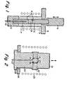
- Two apparati developed in the laboratory for moulding lenses are illustrated schematically in FIGURES 1 and 2, purely by way of example. Hence, for example, the addition of mechanisms for automatic loading and unloading of the glass, alternative sources of heating, cooling, and press motion, and assignment of the essential functions to separate or different mechanical elements are considered to be well within the technical ingenuity of the worker of ordinary skill in the art.
- the moulds 1 and 2 resemble pins which slide inside a bushing 3.
- the optical surfaces or mould cavities 4 are fabricated in the ends of the moulds.
- the geometrical relationship of the optical surfaces to each other, i.e. the tilt and centration, and to the lens mounting surface is controlled by the fit of the moulds within the bushing.
- mould carriers 5 and 6 attached to hydraulic cylinders (not shown) provide the motion to the moulds.
- the lower hydraulic cylinder moves lower mould 1 and bushing 3 into an induction heating coil 7 and holds bushing 3 against a frame 8.
- the upper cylinder forces upper mould 2 against the glass preform 9, causing it to flow. Heating is provided via induction heating and cooling is supplied by natural convection.
- the temperature of the assembly is monitored and controlled by thermocouple 10 in bottom mould 1.
- the moulds 20 and 21 resemble plates with the optical surfaces or mould cavities 22 fabricated into the faces thereof. Moulds 20 and 21 butt into a recess in a ring 23. The faces of the recess control tilt; the edges of the recess control centration.
- the moulds are attached to hydraulic cylinders (not shown) which impart motion thereto.
- the lower hydraulic cylinder moves lower mould 20 upward into contact with the frame 24 and into an induction heating coil 25.
- the upper hydraulic cylinder forces upper mould 21 against glass preform 26.
- the moulds and glass preform are subjected to induction heating and cooling is provided by natural convection.
- the temperature within the assembly is monitored and controlled by thermocouple 27.
- FIGURES 1 and 2 demonstrate two fundamentally different types of pressing operations.
- the volume of the assembly cavity is variable.
- the moulds continue to move until the flowing glass completely fills the cavity.
- the thickness of the resulting lens is determined by the volume of glass in the mould assembly.
- the moulds close to a stop so the volume of the cavity in the assembly is fixed.
- the volume of the glass preform placed in the mould assembly will not completely fill the cavity. This factor results in some free glass surface not constrained by the mould being present on the glass, as indicated by 18 in FIGURE 2.
- the thickness of the lens is governed by the thickness of ring 23.
- High precision glass articles displaying accurate surface figures suitable for optical lenses have been moulded in the laboratory utilizing both methods and apparati, but use of the apparatus represented in FIGURE 1 is preferred.
- the apparatus depicted in FIGURE 1 may also be employed to press glass bodies with a free surface, provided an external stop is attached to the mould carrier.
- the capability of achieving an accurate surface figure in contact with the mould, while a portion of the surface of the glass is unconstrained, is advantageous in furnishing a mechanism for inhibiting the development of a fin on the glass shape.
- a fin is a thin, fragile appendage resulting from glass flowing into a crack between two separate pieces of a mould assembly. Fins can give rise to checks, cracks, abrasion and contamination in a pressing process, as well as cosmetic defects.
- the glass preform, lower mould, and bushing or ring assembled together manually.
- the lower hydraulic cylinder moves this assembly into the induction heating coil.
- the upper mould is thereafter brought into close proximity with the glass.
- An appropriate temperature-pressure sequence is applied to the moulds and glass preform.
- the upper mould is raised, the remaining assembly lowered below the heating coil, and the shaped article removed manually and transferred to a fine annealer.
- FIGURES 1 and 2 preclude the nature of the induction heating disclosed in FIGURES 1 and 2 precludes the likelihood of the temperature of the glass preform differing substantially from that of the mould, that illustrative form of heating should not be deemed to restrict the scope of the invention.
- the flow of the glass preform to conform to the mould is controlled by the following equation: (mould shape, starting glass shape) where to is the time required for conformity, P is the hydrostatic pressure in the glass as it is fully pressed and equals the pressing force divided by cavity surface area, and u is the viscosity of the glass.
- the value of C depends upon the difference between the shape of the mould cavity and the starting shape of the glass, the smaller the difference, the smaller the value of C. Any combination of to, P, and ⁇ yielding the appropriate value of C may be employed to mould the article. For practical reasons, combinations yielding low values of to (pressing time) are to be preferred. Such combinations are highly dependent upon the value of C.
- Example 3 This is illustrated in Example 3, infra, which describes circumstances wherein conformity is achieved at very high glass viscosities because the configuration of the mould surface and the geometry of the glass preform are quite close.
- P pressing pressure
- P appropriate for precision moulding can vary quite broadly. Practical levels range from about 1 to about 50,000 psi (about 7x10 3 to 3.5x10 8 Pa) with the preferred interval encompassing about 500 to 2500 psi (about 3.5x10 6 to 1.7x10 7 P a).
- a batch for a glass consisting essentially, in weight percent on the oxide basis., of about 47.6% P 2 0 5 r 4.3% Na 2 0, 2.1% Li 2 0, 23% BaF 2 . and 23% PbO was melted by conventional means in a platinum crucible. Because it is not known with which cation(s) the fluoride is combined, it is simply tabulated as BaF 2 , the actual batch ingredient employed to incorporate fluoride into the glass composition.
- a bar of glass was cast from the melt and then shaped into a preform having a volume equal to and a geometry similar to that of a desired lens, utilizing forming and shaping technology well known to the glass art.
- the apparatus shown in FIGURE 1 was assembled in the manner described above.
- Moulds having a 10 mm diameter were fabricated from 420M stainless steel with aspheric surface cavities appropriate to a particular lens design.
- the bushing was made from tungsten carbide.
- the assembly was housed in a glove box containing a reducing gas, viz., 92% N 2 and 8% H 2 .
- the mould assembly with the preform therein was heated within the induction coil to 331°C and soaked for five minutes at that temperature to ensure thermal equilibrium. That temperature corresponded to a glass viscosity of about 9 x 10 8 poises (9 x 10 7 Pa.s)
- a force equivalent to 1300 psi (9 x 10 6 Pa) was applied to the mould for one minute.
- the load was released and the mould assembly then cooled rapdily to 280°C, where the glass exhibited a viscosity of about 1 0 12 to 10 13 poises (10 11 - 10 12 Pa.s), the mould disassembled, the resulting lens removed therefrom and placed on its side on a ceramic plate, and the plate and lens transferred to an annealer operating at about 280°C.
- the annealer utilized an air atmosphere and cooled the lens to room temperature at about 50°C/hour.
- the RMS optical path difference between the incoming and existing wavefront was about 0.050 ⁇ .
- the optical performance of the lens is substantially better than the customarily accepted diffraction limit criterion of 0.074 ⁇ .
- a glass preform was prepared having the same composition as, and being shaped in like manner to, the practice described above in Example 1.
- the press shown in FIGURE 1 was assembled with 10 mm diameter moulds having spherical cavities coated with a platinum- rhodium-gold alloy, the bushing being fabricated from tungsten carbide.
- the mould assembly with the preform therein was heated to 338°C in the ambient environment, that temperature corresponding to a glass viscosity of 2 x 10 8 poises (2 x 10 7 Pa.s), and soaked for five minutes.
- a force equivalent to 550 psi (3.8 x 10 6p a) was applied to the moulds for 25 seconds.
- the mould assembly was cooled rapdily to 288°C, this temperature corresponding to a glass viscosity of 10 11 poises (10 10 Pa.s) and then immediately disassembled with the lens being transferred to an annealer.
- the surface of the lens deviated from the spherical by somewhat more than one wavelength.
- Example 2 The conditions of Example 2 were repeated except that the mould assembly was held under load at 288°C for five minutes before disassembly.
- the f 0.8 spherical surface of the lens replicated the mould to within 0.21 ⁇ P-P and 0.030 ⁇ RMS.
- the abbreviation P-P means peak-to-peak.
- the expression represents the difference between the maximum and minimum values of the population.
- RMS signifies root-mean-square.
- the expression designates the square root of the mean of the square of the difference between the values of the population and its mean.
- Example 3 demonstrates that the application of a hold under load at a low temperature, but whereat the glass exhibits a viscosity no greater than 10 12 poises (10 11 Pa.s), for a sufficient length of time to achieve isothermal conditions, allows the glass to conform to the mould, thereby resulting in the production of a lens having a good surface figure.
- a glass pellet was cast from a melt and shaped into a preform in like manner to the procedure described above in Example 1, the glass having the composition described in Example 1.
- the apparatus shown in FIGURE 2 was assembled, the moulds and ring being fabricated of 400 series stainless steels, and the entire assembly with the preform therein being enclosed in a glove box containing a reducing gas, viz., 92% N 2 and 8% H 2 .
- the assembly was heated to 319°C ( ⁇ 3 X 10 9 poises or 3 x 10 8 Pa.s) and soaked at that temperature for four minutes. A force equivalent to 500 psi (3.5 x 10 6 Pa) was applied to the moulds for one minute. With the load still in place, the mould assembly was cooled to 280° C (-7 x 1 0 11 poises or 7 x 1 0 10 P a.s), that temperature held for about five minutes, the assembly thereafter disassembled, and the lens transferred to an annealer operating at about 270°C. The surface of the annealed lens replicated the mould surface to better than 0.25 ⁇ P-P. Both of the moulding steps were undertaken under isothermal conditions. That practice is not mandatory. The second or final pressing must be conducted under isothermal conditions to secure a true surface figure, but the first pressing need not be.
- a glass preform shaped as biconvex with a radius of curvature of 24.0 mm was prepared utilizing 24 mm diameter moulds in a similar manner to that described in Example 1 from a composition consisting essentially, in weight percent on the oxide basis, of about 5.9% PbO, 19.2% K 2 0 + Na 2 0 + CaO, 7.9% B 2 0 3 , and 67% SiO 2 .
- An apparatus paralleling that illustrated in FIGURE 1 was assembled utilizing spherical moulds fabricated from tungsten carbide.
- the preform was placed inside the mould and the assembly heated to 635°C, at which temperature the glass demonstrates a viscosity of 10 9 poises (10 8 Pa.s).
- a load of 12,300 psi (8.5 x 10 7 Pa) was applied to the mould for two minutes. With the load in place, the mould assembly was cooled to 570°C where the glass manifests a viscosity of 10 13 poises (10 12 P a.s).
- the load was removed by lifting upper mould 2 and the lens annealed while resting upon lower mould 1.
- a glass preform of the same geometry and prepared in a similar manner to that described in Example 5 was formed from a composition consisting essentially, in weight percent on the oxide basis, of about 1% MgO, 27% CaO + BaO + Na 2 0 + K 2 0, 0.7% Al 2 O 3 , 0.7% B203, 0.6% Sb 2 O 3 , and 70% Si0 2 .
- the preform was placed inside the mould and the assembly heated to 650°C, at which temperature the glass exhibits a viscosity of 5 x 10 8 poises (5 x 10 7 Pa.s).
- a load of 13,000 psi (9 x 10 7 Pa)' was applied to the mould for two minutes.
- the mould assembly was cooled to 538°C where the glass demonstrates a viscosity of 10 13 poises (10 12 Pa . s ) under a gradually decreasing load such that at 538°C the load was zero.
- Upper mould 2 was lifted and the lens annealed while resting upon lower mould 1.
- a glass preform of the same geometry and prepared in a similar manner as that described in Example 5 was formed from a composition consisting essentially, in weight percent on the oxide basis, of about 2% Na20 + K2 0, 70.5% PbO, 0.5% B203, and 27% Si0 2 .
- the preform was placed inside the mould and the assembly heated to 525°C, at which temperature the glass displays a viscosity of 10 9 poises (10 8 Pa.s).
- a load of 11,600 psi (8 x 10 7 Pa) was applied to the mould for two minutes. With the load in place, the mould assembly was cooled to 445°C where the glass evidences a viscosity of 10 13 poises (1 0 12 P a.s). The load was removed by lifting upper mould 2 and the lens annealed while resting upon lower mould 1.
- the preform was placed into the mould and the temperature thereof raised in concert with the mould, that practice is not a required feature of the process of the invention.
- the preform and mould can be heated to the desired temperature apart from each other and brought together only at the time a load is applied to the mould.
- an initial pressing is undertaken for a brief period at temperatures where the glass is at a viscosity of about 1 0 8 to 10 10 poises (10 7 to 10 9 Pa.s) and, thereafter, the force is maintained on the mould while it is quickly cooled to a temperature where the glass is at a viscosity of about 10 11 to 10 12 poises (10 10 to 10 11 Pa.s).
- the article is removed from the mould. Long hold periods do not adversely affect the character of the shaped body but are not economically desirable.
- An alternative process for conducting the preferred two-step moulding process involves the use of two sets of moulds.
- the first set would be utilized at temperatures where the glass preform is at a viscosity of about 10 8 to 10 16 poises (107 to 10 9 Pa.s).
- the preform After pressing at a temperature within that range, the preform would be removed from the moulds without cooling and with only a potential slight loss of surface figure.
- the glass preform would thereafter be introduced into a second set of moulds and exposed to temperatures where the glass is at a viscosity of about 10 11 to 10 12 poises (10 10 to 10 11 Pa.s).
- a second pressing at those temperatures trues up the surface figure without demanding long moulding times, because the amount of flow experienced by the glass would be very small.
- the second pressing step must be carried out under isothermal conditions whereas such are not required in the first pressing.
- any glass can be moulded into shapes of high precision and excellent surface figure provided mould material is available which is sufficiently refractory and inert to the glass.
- pressing temperatures from 100° to 650°C, preferably, from about 250° to about 450°C are highly desirable.
- glass compositions demonstrating viscosities between 10 8 and 1 0 12 poises (1 0 7 and 10 11 Pa.s) at temperatures over the interval of 100° to 650°C and, preferably, from about 250° to 450°C satisfy those desiderata.
- Phosphate-based glass compositions are recognized in the glass art as commonly possessing low transition temperatures. Such glasses lend themselves well to the moulding technique of the invention. However, phosphate-based glasses are also known in the glass art as frequently exhibiting poor chemical durability.
- UK Patent Specification No. 2069994A discloses glass compositions within the alkali metal alumino- fluorophosphate system demonstrating transition temperatures below 350°C and good weathering resistance which consist essentially, as analyzed in weight percent on the oxide basis, of 30-75% P 2 O 5 , 3-25% R 2 0, wherein R 2 0 consists of O-20% Li 2 0, 0-20% Na 2 0, 0-20% K 2 0, 0-10% Rb 2 0, and 0-10% Cs20, 3-20% A1203, and >3% but ⁇ 24% F, the atomic ratio F:A1 being between 1.5-5 and the atomic ratio R:P being less than 1. Because of their overall properties, those glasses are considered to be the most preferred compositions for use in the process of the present invention.
Landscapes
- Chemical & Material Sciences (AREA)
- Engineering & Computer Science (AREA)
- Materials Engineering (AREA)
- Organic Chemistry (AREA)
- Life Sciences & Earth Sciences (AREA)
- Chemical Kinetics & Catalysis (AREA)
- General Chemical & Material Sciences (AREA)
- Geochemistry & Mineralogy (AREA)
- Manufacturing & Machinery (AREA)
- Glass Compositions (AREA)
- Re-Forming, After-Treatment, Cutting And Transporting Of Glass Products (AREA)
Applications Claiming Priority (2)
| Application Number | Priority Date | Filing Date | Title |
|---|---|---|---|
| US31686181A | 1981-10-30 | 1981-10-30 | |
| US316861 | 1981-10-30 |
Publications (4)
| Publication Number | Publication Date |
|---|---|
| EP0078658A2 true EP0078658A2 (de) | 1983-05-11 |
| EP0078658A3 EP0078658A3 (en) | 1984-01-11 |
| EP0078658B1 EP0078658B1 (de) | 1986-07-16 |
| EP0078658B2 EP0078658B2 (de) | 1992-12-02 |
Family
ID=23231025
Family Applications (1)
| Application Number | Title | Priority Date | Filing Date |
|---|---|---|---|
| EP82305700A Expired - Lifetime EP0078658B2 (de) | 1981-10-30 | 1982-10-27 | Verfahren zum Formen von Glasformlingen |
Country Status (5)
| Country | Link |
|---|---|
| EP (1) | EP0078658B2 (de) |
| JP (3) | JPS5884134A (de) |
| KR (1) | KR860001491B1 (de) |
| DE (1) | DE3272038D1 (de) |
| SG (1) | SG72886G (de) |
Cited By (10)
| Publication number | Priority date | Publication date | Assignee | Title |
|---|---|---|---|---|
| DE3443607A1 (de) * | 1983-11-29 | 1985-06-05 | Hoya Corp., Tokio/Tokyo | Verfahren zur herstellung von optischen linsen |
| DE3729281A1 (de) * | 1987-09-02 | 1989-03-16 | Schott Glaswerke | Verfahren zum herstellen von gepressten glasformkoerpern fuer praezisionsoptische zwecke |
| DE4023975A1 (de) * | 1989-07-28 | 1991-01-31 | Olympus Optical Co | Verfahren zur formung optischer glaskomponenten |
| EP0463463A1 (de) * | 1990-06-13 | 1992-01-02 | Matsushita Electric Industrial Co., Ltd. | Verfahren zur Herstellung optischer Elemente |
| EP0648712A3 (de) * | 1993-10-08 | 1995-07-26 | Matsushita Electric Industrial Co Ltd | Verfahren zum Pressformen eines optischen Elementes. |
| US7497597B2 (en) | 2004-01-19 | 2009-03-03 | Toyoda Gosei Co., Ltd. | Light emitting apparatus |
| DE102008011528A1 (de) | 2008-02-28 | 2009-09-03 | Fraunhofer-Gesellschaft zur Förderung der angewandten Forschung e.V. | Vorrichtung zur Herstellung von Gegenständen aus Glas durch Heißformen und Herstellungsverfahren |
| US7824937B2 (en) | 2003-03-10 | 2010-11-02 | Toyoda Gosei Co., Ltd. | Solid element device and method for manufacturing the same |
| CN102928208A (zh) * | 2011-08-08 | 2013-02-13 | Hoya株式会社 | 非球面玻璃模制透镜的成形难易度预测方法 |
| US20240246849A1 (en) * | 2023-01-19 | 2024-07-25 | Aac Optics (Changzhou) Co., Ltd. | Lens forming method |
Families Citing this family (33)
| Publication number | Priority date | Publication date | Assignee | Title |
|---|---|---|---|---|
| JPS59116137A (ja) * | 1982-12-20 | 1984-07-04 | Canon Inc | 光学素子の製造方法 |
| JPS60221329A (ja) * | 1984-04-18 | 1985-11-06 | Alps Electric Co Ltd | ガラス光学要素の製造方法 |
| JPS60246230A (ja) * | 1984-05-17 | 1985-12-05 | Matsushita Electric Ind Co Ltd | 光学ガラス素子のプレス成形用型 |
| JPS60264333A (ja) * | 1984-06-13 | 1985-12-27 | Matsushita Electric Ind Co Ltd | 光学ガラス素子のプレス成形用型 |
| JPS6121927A (ja) * | 1984-07-09 | 1986-01-30 | Hoya Corp | プレスレンズの製造方法 |
| JPS6148432A (ja) * | 1984-08-16 | 1986-03-10 | Hoya Corp | 高精度プレスレンズの成形方法 |
| JPS6126528A (ja) * | 1984-07-14 | 1986-02-05 | Hoya Corp | プレスレンズを製造する装置 |
| JPS6144721A (ja) * | 1984-08-08 | 1986-03-04 | Hoya Corp | ガラスレンズプレス成形装置 |
| JPS6153126A (ja) * | 1984-08-20 | 1986-03-17 | Hoya Corp | 高精度プレスレンズの成形方法 |
| JPS61132523A (ja) * | 1984-11-29 | 1986-06-20 | Hoya Corp | ガラス成形体を得る方法 |
| JPS61136927A (ja) * | 1984-12-05 | 1986-06-24 | Olympus Optical Co Ltd | 光学素子の成形方法 |
| JPS61136928A (ja) * | 1984-12-10 | 1986-06-24 | Matsushita Electric Ind Co Ltd | 光学ガラス素子のプレス成形用型 |
| JPH0653580B2 (ja) * | 1985-03-30 | 1994-07-20 | 松下電器産業株式会社 | ガラスレンズ成形装置 |
| JPS6291430A (ja) * | 1985-06-27 | 1987-04-25 | Hoya Corp | ガラス成形体のプレス成形方法 |
| JPH0615414B2 (ja) * | 1985-08-13 | 1994-03-02 | 松下電器産業株式会社 | レンズ成形方法 |
| JPH0617240B2 (ja) * | 1985-11-26 | 1994-03-09 | 松下電器産業株式会社 | ガラスレンズの成形方法 |
| US5173100A (en) * | 1988-11-16 | 1992-12-22 | Canon Kabushiki Kaisha | Molding method for optical element |
| JP2501230B2 (ja) * | 1988-12-13 | 1996-05-29 | キヤノン株式会社 | レンズの成形用型 |
| JP2669476B2 (ja) * | 1989-12-06 | 1997-10-27 | キヤノン株式会社 | 光学素子の製造方法 |
| US5250099A (en) * | 1990-03-29 | 1993-10-05 | Canon Kabushiki Kaisha | Glass molding process and molding apparatus for the same |
| JPH0431328A (ja) * | 1990-05-25 | 1992-02-03 | Canon Inc | 光学素子成形用型構造及びプレス成形方法 |
| US5188652A (en) * | 1990-10-26 | 1993-02-23 | Matsushita Electric Industrial Co., Ltd. | Machine for molding optical element |
| US5201927A (en) * | 1990-10-26 | 1993-04-13 | Matsushita Electric Industrial Co., Ltd. | Method of producing the optical element |
| US5215566A (en) * | 1991-01-18 | 1993-06-01 | Canon Kabushiki Kaisha | Method of manufacturing optical element |
| US5322541A (en) * | 1991-03-28 | 1994-06-21 | Matsushita Electric Industrial Co., Ltd. | Method of producing glass blank |
| JP2790262B2 (ja) * | 1991-07-19 | 1998-08-27 | キヤノン株式会社 | 光学素子のプレス成形方法 |
| JPH0948621A (ja) * | 1995-08-04 | 1997-02-18 | Canon Inc | 光学素子の成形方法 |
| JP2003054968A (ja) * | 2001-08-22 | 2003-02-26 | Olympus Optical Co Ltd | 光学素子の成形方法 |
| JP4008943B2 (ja) * | 2003-03-10 | 2007-11-14 | 豊田合成株式会社 | 固体素子デバイスの製造方法 |
| DE102007044517A1 (de) * | 2007-09-18 | 2009-03-19 | Docter Optics Gmbh | Verfahren zum Herstellen einer Scheinwerferlinse für einen Fahrzeugscheinwerfer |
| JP2010105830A (ja) * | 2008-10-28 | 2010-05-13 | Olympus Corp | 光学素子の製造方法 |
| JP6257465B2 (ja) * | 2014-07-18 | 2018-01-10 | オリンパス株式会社 | 光学素子の製造方法 |
| JP7201332B2 (ja) * | 2018-04-09 | 2023-01-10 | トヨタ自動車株式会社 | 希土類磁石の製造方法及びそれに用いられる製造装置 |
Family Cites Families (15)
| Publication number | Priority date | Publication date | Assignee | Title |
|---|---|---|---|---|
| US1812564A (en) * | 1930-04-09 | 1931-06-30 | Macbeth Evans Glass Co | Method of pressing glassware |
| GB378199A (en) * | 1931-08-01 | 1932-08-11 | Taylor William | Improved methods of lens production |
| US2432668A (en) * | 1942-03-16 | 1947-12-16 | Kingston Arthur William | Production of optical lenses, prisms, and like optical elements |
| US3833347A (en) * | 1970-11-27 | 1974-09-03 | Eastman Kodak Co | Method for molding glass lenses |
| CA968560A (en) * | 1970-11-27 | 1975-06-03 | Gerald E. Blair | Method for molding glass lenses |
| JPS5029668Y2 (de) * | 1972-07-10 | 1975-09-01 | ||
| GB1446413A (en) * | 1972-10-20 | 1976-08-18 | Pilkington Brothers Ltd | Molding glass articles |
| US3844755A (en) * | 1972-11-16 | 1974-10-29 | Eastman Kodak Co | Method and apparatus for transfer molding glass lenses |
| FR2322835A1 (fr) * | 1975-09-02 | 1977-04-01 | Eastman Kodak Co | Procede de moulage d'elements optiques en verre et moule pour leur fabrication |
| JPS5386710A (en) * | 1977-01-12 | 1978-07-31 | Obara Optical Glass | Pressure molding of lump glass |
| JPS5438126A (en) * | 1977-09-01 | 1979-03-22 | Olympus Optical Co Ltd | Electrophotography for plural copies |
| JPS5562815A (en) * | 1978-11-06 | 1980-05-12 | Ohara Inc | Press molding method for thick optical glass molding |
| JPS56378A (en) * | 1979-06-15 | 1981-01-06 | Teijin Ltd | Production of suede like raised fabric |
| DE3037004A1 (de) * | 1979-10-05 | 1981-04-16 | Corning Glass Works, Corning, N.Y. | Bei niedrigen temperaturen formbare glaeser |
| JPS6132263A (ja) * | 1984-07-23 | 1986-02-14 | Sony Corp | フロントロ−デイング方式レコ−ドプレ−ヤ |
-
1982
- 1982-10-25 KR KR8204700A patent/KR860001491B1/ko not_active Expired
- 1982-10-27 EP EP82305700A patent/EP0078658B2/de not_active Expired - Lifetime
- 1982-10-27 DE DE8282305700T patent/DE3272038D1/de not_active Expired
- 1982-10-28 JP JP57189975A patent/JPS5884134A/ja active Granted
-
1986
- 1986-09-11 SG SG728/86A patent/SG72886G/en unknown
-
1987
- 1987-06-17 JP JP62150823A patent/JPS632822A/ja active Granted
-
1993
- 1993-09-02 JP JP5218447A patent/JPH06211528A/ja active Pending
Cited By (15)
| Publication number | Priority date | Publication date | Assignee | Title |
|---|---|---|---|---|
| DE3443607A1 (de) * | 1983-11-29 | 1985-06-05 | Hoya Corp., Tokio/Tokyo | Verfahren zur herstellung von optischen linsen |
| DE3729281A1 (de) * | 1987-09-02 | 1989-03-16 | Schott Glaswerke | Verfahren zum herstellen von gepressten glasformkoerpern fuer praezisionsoptische zwecke |
| DE4023975A1 (de) * | 1989-07-28 | 1991-01-31 | Olympus Optical Co | Verfahren zur formung optischer glaskomponenten |
| EP0463463A1 (de) * | 1990-06-13 | 1992-01-02 | Matsushita Electric Industrial Co., Ltd. | Verfahren zur Herstellung optischer Elemente |
| US5160361A (en) * | 1990-06-13 | 1992-11-03 | Matsushita Electric Industrial Co., Ltd. | Method of manufacturing optical element |
| US5630859A (en) * | 1993-10-08 | 1997-05-20 | Matsushita Electric Industrial Co., Ltd. | Optical element forming method |
| EP0648712A3 (de) * | 1993-10-08 | 1995-07-26 | Matsushita Electric Industrial Co Ltd | Verfahren zum Pressformen eines optischen Elementes. |
| US7824937B2 (en) | 2003-03-10 | 2010-11-02 | Toyoda Gosei Co., Ltd. | Solid element device and method for manufacturing the same |
| US8154047B2 (en) | 2003-03-10 | 2012-04-10 | Toyoda Gosei Co., Ltd. | Solid element device and method for manufacturing the same |
| US8685766B2 (en) | 2003-03-10 | 2014-04-01 | Toyoda Gosei Co., Ltd. | Solid element device and method for manufacturing the same |
| US7497597B2 (en) | 2004-01-19 | 2009-03-03 | Toyoda Gosei Co., Ltd. | Light emitting apparatus |
| DE102008011528A1 (de) | 2008-02-28 | 2009-09-03 | Fraunhofer-Gesellschaft zur Förderung der angewandten Forschung e.V. | Vorrichtung zur Herstellung von Gegenständen aus Glas durch Heißformen und Herstellungsverfahren |
| CN102928208A (zh) * | 2011-08-08 | 2013-02-13 | Hoya株式会社 | 非球面玻璃模制透镜的成形难易度预测方法 |
| CN102928208B (zh) * | 2011-08-08 | 2017-04-12 | Hoya株式会社 | 非球面玻璃模制透镜的成形难易度预测方法 |
| US20240246849A1 (en) * | 2023-01-19 | 2024-07-25 | Aac Optics (Changzhou) Co., Ltd. | Lens forming method |
Also Published As
| Publication number | Publication date |
|---|---|
| KR860001491B1 (ko) | 1986-09-27 |
| EP0078658B1 (de) | 1986-07-16 |
| SG72886G (en) | 1987-03-27 |
| JPS5884134A (ja) | 1983-05-20 |
| DE3272038D1 (en) | 1986-08-21 |
| JPH06211528A (ja) | 1994-08-02 |
| JPS632822A (ja) | 1988-01-07 |
| EP0078658A3 (en) | 1984-01-11 |
| JPS6132263B2 (de) | 1986-07-25 |
| JPH0432008B2 (de) | 1992-05-28 |
| KR840001935A (ko) | 1984-06-07 |
| EP0078658B2 (de) | 1992-12-02 |
Similar Documents
| Publication | Publication Date | Title |
|---|---|---|
| EP0078658B2 (de) | Verfahren zum Formen von Glasformlingen | |
| US4481023A (en) | Process to mold precision glass articles | |
| US4734118A (en) | Process to mold precision glass articles | |
| US4969944A (en) | Process to mold precision glass articles | |
| US3833347A (en) | Method for molding glass lenses | |
| US4854958A (en) | Process to mold precision glass articles | |
| US3900328A (en) | Method and apparatus for molding glass lenses | |
| US4747864A (en) | Process for the precision molding of glass articles | |
| US9688562B2 (en) | Method of making shaped glass articles | |
| US3844755A (en) | Method and apparatus for transfer molding glass lenses | |
| US5346523A (en) | Method of molding chalcogenide glass lenses | |
| JP2006504609A5 (de) | ||
| US20050274145A1 (en) | Low-temperature fabrication of glass optical components | |
| US4929265A (en) | Method of molding glass optical elements | |
| US6070436A (en) | Manufacturing method for molded glass articles | |
| US4883528A (en) | Apparatus for molding glass optical elements | |
| US4964903A (en) | Apparatus for molding glass molds | |
| EP0057952B1 (de) | Verfahren zur Präzisionsherstellung von Glasartikeln, Verfahren zur Herstellung einer Form und Form für die Präzisionsherstellung von Glasartikeln | |
| US4897101A (en) | Method of forming a precision glass mold and article | |
| JPH1045419A (ja) | ガラス被覆層を有するガラスレンズ及びその製造方法 | |
| JPH0231012B2 (de) | ||
| AU625180B2 (en) | Molding apparatus and method | |
| JPH021779B2 (de) | ||
| JPH05330832A (ja) | カルコゲナイドガラスレンズの成形方法 | |
| JPH021778B2 (de) |
Legal Events
| Date | Code | Title | Description |
|---|---|---|---|
| PUAI | Public reference made under article 153(3) epc to a published international application that has entered the european phase |
Free format text: ORIGINAL CODE: 0009012 |
|
| AK | Designated contracting states |
Designated state(s): DE FR GB NL |
|
| PUAL | Search report despatched |
Free format text: ORIGINAL CODE: 0009013 |
|
| AK | Designated contracting states |
Designated state(s): DE FR GB NL |
|
| 17P | Request for examination filed |
Effective date: 19840619 |
|
| GRAA | (expected) grant |
Free format text: ORIGINAL CODE: 0009210 |
|
| AK | Designated contracting states |
Kind code of ref document: B1 Designated state(s): DE FR GB NL |
|
| REF | Corresponds to: |
Ref document number: 3272038 Country of ref document: DE Date of ref document: 19860821 |
|
| ET | Fr: translation filed | ||
| PLBI | Opposition filed |
Free format text: ORIGINAL CODE: 0009260 |
|
| PLBI | Opposition filed |
Free format text: ORIGINAL CODE: 0009260 |
|
| 26 | Opposition filed |
Opponent name: SCHOTT GLASWERKE Effective date: 19870407 |
|
| NLR1 | Nl: opposition has been filed with the epo |
Opponent name: SCHOTT GLASWERKE |
|
| 26 | Opposition filed |
Opponent name: N.V. PHILIPS' GLOEILAMPENFABRIEKEN Effective date: 19870415 |
|
| NLR1 | Nl: opposition has been filed with the epo |
Opponent name: N.V. PHILIPS GLOEILAMPENFABRIEKEN |
|
| PLAB | Opposition data, opponent's data or that of the opponent's representative modified |
Free format text: ORIGINAL CODE: 0009299OPPO |
|
| R26 | Opposition filed (corrected) |
Opponent name: SCHOTT GLASWERKE * 870415 N.V. PHILIPS' GLOEILAMPE Effective date: 19870407 |
|
| PLAB | Opposition data, opponent's data or that of the opponent's representative modified |
Free format text: ORIGINAL CODE: 0009299OPPO |
|
| R26 | Opposition filed (corrected) |
Opponent name: SCHOTT GLASWERKE * 870415 N.V. PHILIPS' GLOEILAMPE Effective date: 19870407 |
|
| PLAB | Opposition data, opponent's data or that of the opponent's representative modified |
Free format text: ORIGINAL CODE: 0009299OPPO |
|
| R26 | Opposition filed (corrected) |
Opponent name: SCHOTT GLASWERKE * 870415 N.V. PHILIPS' GLOEILAMPE Effective date: 19870407 |
|
| PUAH | Patent maintained in amended form |
Free format text: ORIGINAL CODE: 0009272 |
|
| STAA | Information on the status of an ep patent application or granted ep patent |
Free format text: STATUS: PATENT MAINTAINED AS AMENDED |
|
| 27A | Patent maintained in amended form |
Effective date: 19921202 |
|
| AK | Designated contracting states |
Kind code of ref document: B2 Designated state(s): DE FR GB NL |
|
| NLR2 | Nl: decision of opposition | ||
| ET3 | Fr: translation filed ** decision concerning opposition | ||
| NLR3 | Nl: receipt of modified translations in the netherlands language after an opposition procedure | ||
| PGFP | Annual fee paid to national office [announced via postgrant information from national office to epo] |
Ref country code: GB Payment date: 19950918 Year of fee payment: 14 |
|
| PGFP | Annual fee paid to national office [announced via postgrant information from national office to epo] |
Ref country code: NL Payment date: 19951004 Year of fee payment: 14 |
|
| PGFP | Annual fee paid to national office [announced via postgrant information from national office to epo] |
Ref country code: FR Payment date: 19951020 Year of fee payment: 14 |
|
| PGFP | Annual fee paid to national office [announced via postgrant information from national office to epo] |
Ref country code: DE Payment date: 19951027 Year of fee payment: 14 |
|
| PG25 | Lapsed in a contracting state [announced via postgrant information from national office to epo] |
Ref country code: GB Effective date: 19961027 |
|
| PG25 | Lapsed in a contracting state [announced via postgrant information from national office to epo] |
Ref country code: NL Effective date: 19970501 |
|
| GBPC | Gb: european patent ceased through non-payment of renewal fee |
Effective date: 19961027 |
|
| PG25 | Lapsed in a contracting state [announced via postgrant information from national office to epo] |
Ref country code: FR Effective date: 19970630 |
|
| NLV4 | Nl: lapsed or anulled due to non-payment of the annual fee |
Effective date: 19970501 |
|
| PG25 | Lapsed in a contracting state [announced via postgrant information from national office to epo] |
Ref country code: DE Effective date: 19970701 |
|
| REG | Reference to a national code |
Ref country code: FR Ref legal event code: ST |
|
| APAH | Appeal reference modified |
Free format text: ORIGINAL CODE: EPIDOSCREFNO |