EP0143656A2 - Halbleiteranordnung mit Verbindungshalbleiter und Verfahren zu dessen Herstellung - Google Patents
Halbleiteranordnung mit Verbindungshalbleiter und Verfahren zu dessen Herstellung Download PDFInfo
- Publication number
- EP0143656A2 EP0143656A2 EP84308259A EP84308259A EP0143656A2 EP 0143656 A2 EP0143656 A2 EP 0143656A2 EP 84308259 A EP84308259 A EP 84308259A EP 84308259 A EP84308259 A EP 84308259A EP 0143656 A2 EP0143656 A2 EP 0143656A2
- Authority
- EP
- European Patent Office
- Prior art keywords
- layer
- semiconductor layer
- electron
- mode transistor
- semiconductor
- Prior art date
- Legal status (The legal status is an assumption and is not a legal conclusion. Google has not performed a legal analysis and makes no representation as to the accuracy of the status listed.)
- Granted
Links
Images


Classifications
-
- H—ELECTRICITY
- H10—SEMICONDUCTOR DEVICES; ELECTRIC SOLID-STATE DEVICES NOT OTHERWISE PROVIDED FOR
- H10D—INORGANIC ELECTRIC SEMICONDUCTOR DEVICES
- H10D84/00—Integrated devices formed in or on semiconductor substrates that comprise only semiconducting layers, e.g. on Si wafers or on GaAs-on-Si wafers
- H10D84/80—Integrated devices formed in or on semiconductor substrates that comprise only semiconducting layers, e.g. on Si wafers or on GaAs-on-Si wafers characterised by the integration of at least one component covered by groups H10D12/00 or H10D30/00, e.g. integration of IGFETs
- H10D84/82—Integrated devices formed in or on semiconductor substrates that comprise only semiconducting layers, e.g. on Si wafers or on GaAs-on-Si wafers characterised by the integration of at least one component covered by groups H10D12/00 or H10D30/00, e.g. integration of IGFETs of only field-effect components
- H10D84/83—Integrated devices formed in or on semiconductor substrates that comprise only semiconducting layers, e.g. on Si wafers or on GaAs-on-Si wafers characterised by the integration of at least one component covered by groups H10D12/00 or H10D30/00, e.g. integration of IGFETs of only field-effect components of only insulated-gate FETs [IGFET]
- H10D84/84—Combinations of enhancement-mode IGFETs and depletion-mode IGFETs
-
- H—ELECTRICITY
- H10—SEMICONDUCTOR DEVICES; ELECTRIC SOLID-STATE DEVICES NOT OTHERWISE PROVIDED FOR
- H10D—INORGANIC ELECTRIC SEMICONDUCTOR DEVICES
- H10D30/00—Field-effect transistors [FET]
- H10D30/40—FETs having zero-dimensional [0D], one-dimensional [1D] or two-dimensional [2D] charge carrier gas channels
- H10D30/47—FETs having zero-dimensional [0D], one-dimensional [1D] or two-dimensional [2D] charge carrier gas channels having two-dimensional [2D] charge carrier gas channels, e.g. nanoribbon FETs or high electron mobility transistors [HEMT]
- H10D30/471—High electron mobility transistors [HEMT] or high hole mobility transistors [HHMT]
- H10D30/475—High electron mobility transistors [HEMT] or high hole mobility transistors [HHMT] having wider bandgap layer formed on top of lower bandgap active layer, e.g. undoped barrier HEMTs such as i-AlGaN/GaN HEMTs
- H10D30/4755—High electron mobility transistors [HEMT] or high hole mobility transistors [HHMT] having wider bandgap layer formed on top of lower bandgap active layer, e.g. undoped barrier HEMTs such as i-AlGaN/GaN HEMTs having wide bandgap charge-carrier supplying layers, e.g. modulation doped HEMTs such as n-AlGaAs/GaAs HEMTs
-
- H—ELECTRICITY
- H10—SEMICONDUCTOR DEVICES; ELECTRIC SOLID-STATE DEVICES NOT OTHERWISE PROVIDED FOR
- H10D—INORGANIC ELECTRIC SEMICONDUCTOR DEVICES
- H10D84/00—Integrated devices formed in or on semiconductor substrates that comprise only semiconducting layers, e.g. on Si wafers or on GaAs-on-Si wafers
- H10D84/01—Manufacture or treatment
- H10D84/0123—Integrating together multiple components covered by H10D12/00 or H10D30/00, e.g. integrating multiple IGBTs
- H10D84/0126—Integrating together multiple components covered by H10D12/00 or H10D30/00, e.g. integrating multiple IGBTs the components including insulated gates, e.g. IGFETs
- H10D84/0163—Integrating together multiple components covered by H10D12/00 or H10D30/00, e.g. integrating multiple IGBTs the components including insulated gates, e.g. IGFETs the components including enhancement-mode IGFETs and depletion-mode IGFETs
-
- H—ELECTRICITY
- H10—SEMICONDUCTOR DEVICES; ELECTRIC SOLID-STATE DEVICES NOT OTHERWISE PROVIDED FOR
- H10D—INORGANIC ELECTRIC SEMICONDUCTOR DEVICES
- H10D84/00—Integrated devices formed in or on semiconductor substrates that comprise only semiconducting layers, e.g. on Si wafers or on GaAs-on-Si wafers
- H10D84/01—Manufacture or treatment
- H10D84/02—Manufacture or treatment characterised by using material-based technologies
- H10D84/03—Manufacture or treatment characterised by using material-based technologies using Group IV technology, e.g. silicon technology or silicon-carbide [SiC] technology
- H10D84/038—Manufacture or treatment characterised by using material-based technologies using Group IV technology, e.g. silicon technology or silicon-carbide [SiC] technology using silicon technology, e.g. SiGe
-
- H—ELECTRICITY
- H10—SEMICONDUCTOR DEVICES; ELECTRIC SOLID-STATE DEVICES NOT OTHERWISE PROVIDED FOR
- H10D—INORGANIC ELECTRIC SEMICONDUCTOR DEVICES
- H10D84/00—Integrated devices formed in or on semiconductor substrates that comprise only semiconducting layers, e.g. on Si wafers or on GaAs-on-Si wafers
- H10D84/01—Manufacture or treatment
- H10D84/02—Manufacture or treatment characterised by using material-based technologies
- H10D84/05—Manufacture or treatment characterised by using material-based technologies using Group III-V technology
-
- H—ELECTRICITY
- H10—SEMICONDUCTOR DEVICES; ELECTRIC SOLID-STATE DEVICES NOT OTHERWISE PROVIDED FOR
- H10P—GENERIC PROCESSES OR APPARATUS FOR THE MANUFACTURE OR TREATMENT OF DEVICES COVERED BY CLASS H10
- H10P50/00—Etching of wafers, substrates or parts of devices
- H10P50/20—Dry etching; Plasma etching; Reactive-ion etching
- H10P50/24—Dry etching; Plasma etching; Reactive-ion etching of semiconductor materials
- H10P50/246—Dry etching; Plasma etching; Reactive-ion etching of semiconductor materials of Group III-V materials
-
- Y—GENERAL TAGGING OF NEW TECHNOLOGICAL DEVELOPMENTS; GENERAL TAGGING OF CROSS-SECTIONAL TECHNOLOGIES SPANNING OVER SEVERAL SECTIONS OF THE IPC; TECHNICAL SUBJECTS COVERED BY FORMER USPC CROSS-REFERENCE ART COLLECTIONS [XRACs] AND DIGESTS
- Y10—TECHNICAL SUBJECTS COVERED BY FORMER USPC
- Y10S—TECHNICAL SUBJECTS COVERED BY FORMER USPC CROSS-REFERENCE ART COLLECTIONS [XRACs] AND DIGESTS
- Y10S148/00—Metal treatment
- Y10S148/131—Reactive ion etching rie
-
- Y—GENERAL TAGGING OF NEW TECHNOLOGICAL DEVELOPMENTS; GENERAL TAGGING OF CROSS-SECTIONAL TECHNOLOGIES SPANNING OVER SEVERAL SECTIONS OF THE IPC; TECHNICAL SUBJECTS COVERED BY FORMER USPC CROSS-REFERENCE ART COLLECTIONS [XRACs] AND DIGESTS
- Y10—TECHNICAL SUBJECTS COVERED BY FORMER USPC
- Y10S—TECHNICAL SUBJECTS COVERED BY FORMER USPC CROSS-REFERENCE ART COLLECTIONS [XRACs] AND DIGESTS
- Y10S148/00—Metal treatment
- Y10S148/168—V-Grooves
Definitions
- the present invention relates to a semiconductor device comprising an enhancement-mode field-effect transistor and a depletion-mode field-effect transistor, each of which has a heterojunction and uses a two-dimensional electron gas.
- transistors made of a compound semiconductor such as gallium-arsenide (GaAs) since its carrier mobility is far greater than that of silicon (Si), which is generally used conventionally in semiconductor devices.
- Field-effect transistors, particularly Schottky barrier-type field-effect transistors, are generally produced as the transistors formed by a compound semiconductor, since the production process is easier than that for bipolar transistors.
- a field-effect transistor made of GaAs or Si and having a conventional structure, carriers move in a semiconductor crystal in which impurity ions exist.
- the moving carriers are scattered by the lattice vibration and the impurity ions, whereby the carrier mobility is limited.
- the lattice scattering effect can be reduced by lowering the temperature, but the ionized impurity scattering effect is not reduced.
- the heterojunction-type field-effect transistor comprises a semi-insulating GaAs substrate, an undoped GaAs layer (semiconductor channel layer), an N-type aluminium-gallium-arsenide layer (AlGaAs; electron-supply layer), and an N-type GaAs layer (contact layer), which layers are formed in sequence on the GaAs substrate by a molecular beam epitaxy (MBE) method or a metal organic chemical vapour deposition (MOCVD) method.
- MBE molecular beam epitaxy
- MOCVD metal organic chemical vapour deposition
- the undoped GaAs layer and the N-type AlGaAs layer form the heterojunction.
- the N-type AlGaAs layer has an electron affinity smaller than that of the undoped GaAs layer and contains donor impurities.
- the N-type GaAs layer and, if necessary, the N-type AlGaAs layer are selectively etched to form a groove for a gate electrode so that a predetermined distance between the top surface of the undoped GaAs layer (i.e., the interface of the heterojunction) and the bottom of the gate electrode is obtained.
- the distance has an influence on the gate threshold voltage of the field-effect transistor.
- a two-dimensional electron gas is generated in the undoped GaAs layer at the heterojunction interface by transferring electrons into the undoped GaAs layer from the N-type AlGaAs layer and serves as a channel.
- the electron density of the channel is controlled by an applied voltage of the gate so that the impedance between the source electrode and the drain electrode is controlled.
- a semiconductor device comprising an enhancement-mode transistor and a depletion-mode transistor is produced by using the above-mentioned heterojunction-type field-effect transistor, namely, when at least two heterojunction-type field-effect transistors having different gate threshold voltages are produced on the same semi-insulating GaAs substrate by varying a thickness of the N-type GaAs and, if necessary, the N-type AlGaAs under the gate electrodes, it is necessary to form suitable grooves for the gate electrodes by accurately etching the layers formed on the undoped GaAs layer, respectively.
- etching process is complicated, and accurate etching control is difficult.
- a semiconductor device which includes an enhancement-mode transistor and a depletion-mode transistor, has a heterojunction, and uses a two-dimensional electron gas, comprising: a semi-insulating compound semiconductor substrate; a semiconductor channel layer which is formed on the substrate and in which the two-dimensional electron gas is generated; an electron-supply region including an electron supply layer formed on the semiconductor channel layer and forming the heterojunction with it; a first semiconductor layer formed on the electron-supply region and having a composition different from the electron-supply layer; and gate electrodes of the enhancement-mode transistor and the depletion-mode transistor; is characterised in that the semiconductor device also includes a second semiconductor layer formed on the first semiconductor layer and having a composition different from the first semiconductor layer, the gate electrode of the depletion-mode transistor being located on the electron-supply region, and the gate electrode of the enhancement-mode transistor being located in the electron-supply region at a depth from the base of the first semiconductor layer corresponding to the thickness of the second semiconductor layer.
- the gate electrode in the electron supply region by including in the electron supply region a third semiconductor layer and a fourth semiconductor layer, the third semi-conductor layer being of the same material as the first semiconductor layer and being formed on the electron supply layer, and the fourth semiconductor layer being of the same material as the second semiconductor layer, having the same thickness as the second semiconductor layer and being formed on the third semiconductor layer; the gate electrode of the depletion-mode transistor being located on the fourth semiconductor layer and the gate electrode of the enhancement-mode transistor being located on the electron-supply layer.
- the invention also encompasses the methods of making such devices.
- an inverter has a conventional structure comprising an enhancement-mode field-effect transistor in an "E” section and a depletion-mode field-effect transistor in a "D” section.
- the inverter has the electric circuit of Figure 2, in which "Tr l " corresponds to a driven element of the enhancement-mode field-effect transistor and "Tr 2 " corresponds to a load element of the depletion-mode field-effect transistor.
- Each of the transistors comprises a semi-insulating GaAs substrate 1, an undoped GaAs layer (semiconductor channel layer) 2, an N-type AlGaAs layer (electron-supply layer) 3, and an N-type GaAs layer (contact or cap layer) 4, which layers are formed in sequence on the substrate 1 by the MBE method or the MOCVD method.
- the formed layers are selectively etched to form an active mesa portion isolated from another active mesa portion (not shown), as shown in Figure 1. It is possible to use another isolation structure, e.g., an insulator region which is doped with oxygen ions or protons.
- Source and drain electrodes 5a, 5b and 5c of AuGe/Au, AuGe/Ni/Au, or AuGe/Ni are formed on the N-type GaAs layer 4. Alloyed regions 6a, 6b, and 6c are formed under the electrodes 5a, 5b, and 5c by a heat treatment.
- the enhancement-mode transistor has the source electrode 5a and the drain electrode 5b, and the depletion-mode transistor has the source electrode 5b and the drain electrode 5c. In this case, the electrode 5b serves as a common electrode.
- a gate electrode 7a of the enhancement-mode transistor is formed in a groove which extends into a portion of the N-type AlGaAs layer 3 through the N-type GaAs layer 4, while a gate electrode 7b of the depletion-mode transistor is formed in another groove which extends to the top surface of the N-type AlGaAs layer 3 through the N-type GaAs layer 4.
- An insulating layer 8 of, e.g., silicon dioxide (Si0 2 ) is formed, and suitable internal connector lines 9a, 9b, and 9c are formed.
- a two-dimensional electron gas 2a is generated in the undoped GaAs layer 2 at the interface of the heterojunction (of the GaAs layer and the AlGaAs layer) between the alloyed regions 6a, 6b and 6c, as shown in Figure 1.
- the two-dimensional electron gas 2a serves as a channel of the field-effect transistor and is controlled by the gate voltage.
- the gate threshold voltage V th is related to the distance between the interface of the heterojunction and the bottom of the gate electrode, for example, as shown in Figure 3.
- the gate threshold voltage of the depletion-mode transistor is, e.g., -0.3 volts (i.e., V th -0.3 V)
- the distance is about 46.5 nm.
- the etching step for a groove and the formation step of a gate electrode are repeated twice for the enhancement-mode and depletion-mode transistors.
- the AlGaAs layer 3 is adopted for use as an etching-stopping layer for the formation of the groove of the gate electrode 7b of the depletion-mode transistor, as shown in Figure 1.
- the groove for the depletion-mode transistor can be relatively easily formed, but the etching process for the groove for the enhancement-mode transistor should be stopped so as to obtain a groove having a predetermined depth in the AlGaAs layer 3.
- the current between the source and the drain is often monitored. Since the monitoring measurement must be performed outside of the etching apparatus, the production efficiency is remarkably reduced. Further more, when many enhancement-mode and depletion-mode transistors are produced on a substrate, the variation of the gate threshold voltage must be minimized.
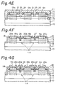
- an undoped GaAs layer 11 is formed by the MBE method or the MOCVD method.
- the GaAs layer 11 has a thickness of from 0.1 to 0.3 ⁇ m.
- An N-type AlGaAs layer (electron-supply layer) 12 is epitaxially grown on the undoped GaAs layer 11 so that the AlGaAs layer 12 and the GaAs layer 11 form a heterojunction.
- the Al x Ga 1 - x As layer 12 is doped with Si impurities of a dose of from 1 x 10 17 to 2 x 10 cm and has a thickness of e.g., 48 nm, which corresponds to the distance between the heterojunction interface and the bottom of the gate electrode of the depletion-mode transistor plus an overetching depth during the etching step for grooves, wherein "x" is 0.3.
- an N-type GaAs layer 13 is epitaxially grown on the AlGaAs layer 12.
- the GaAs layer 13 has a thickness of, e.g., approximately 100 nm and is doped with Si impurities of a dose of from 1 x 10 to 2 x 10 cm -3 .
- the layers 11, 12 and 13 are similar to those of a conventional semiconductor device, shown e.g. in Figure 1.
- an N-type AlGaAs layer 14 is epitaxially grown on the GaAs layer 13.
- the AlGaAs layer 14 has the substantially same composition as that of the AlGaAs layer 12 and has a thickness corresponding to the difference in distance between the heterojunction interface and the gate electrode bottom for the enhancement-mode transistor and the depletion-mode transistor, e.g., 4 nm.
- An N-type GaAs layer 15 is epitaxially grown on the AlGaAs layer 14, as shown in Figure 4A.
- the GaAs layer 15 serves as a cap-protecting layer to prevent the thickness and the surface properties of the AlGaAs layer 14 from undesirably changing due to a wafer surface treatment, such as an etching treatment, a cleaning treatment (involving the oxidation of Al), or the like. It is possible to adopt undoped AlGaAs and undoped GaAs for the layers 14 and 15, respectively, instead of N-type AlGaAs and N-type GaAs.
- the layers 12, 13, 14 and 15 are formed by the MBE method or the MOCVD method.
- the formed layers 11 to 15 are selectively etched by a wet etching method or a dry etching method so as to form an isolated mesa portion 16 in which transistors are formed.
- the etching depth extends into the undoped GaAs layer 11 to attain isolation between elements. It is possible to adopt another isolation structure, e.g., an insulator region which is doped with oxygen ions or protons by an ion-implantation method.
- portions of the GaAs layer 15 and the AlGaAs layer 14 corresponding to a gate region of the enhancement-mode transistor are etched by a suitable etching method to form a recess 17 in which the N-type GaAs layer 13 is exposed.
- a small portion of the N-type GaAs layer 13 may be etched.
- the exposed surface of the compound semiconductor substrate including the mesa portion 16 is covered with an insulating protector film 18, e.g., of Si0 2 .
- the film 18 is selectively etched by a conventional lithograph method to form openings for source and drain electrodes.
- the GaAs layer 15, the AlGaAs layer 14, and a portion of the N-type GaAs layer 13 are etched through the openings by a suitable etching method.
- ohmic contact electrodes 19a, 19b, and 19c are formed in the openings by depositing a multilayer metal of AuGe/Au, AuGe/Ni/Au, AuGe/Ni, or the like and patterning it by a lift-off method or a lithograph method.
- a heat treatment for alloying e.g., at approximately 450°C for 1 minute is carried out to form alloyed regions 20a, 20b, and 20c coming into ohmic contact with a two-dimensional electron gas layer.
- the etching step of the layers 15, 14, and 13 is not always necessary.
- a resist film (preferably a positive photoresist film) 21 is applied on the entire exposed surface and is patterned to form openings 22 and 23 corresponding to gate regions of the enhancement-mode and depletion-mode transistors.
- the insulating protector (Si0 2 ) film 19 is etched through the openings 22 and 23 by a suitable etchant (e.g., a hydrofluoric acid).
- a suitable etchant e.g., a hydrofluoric acid.
- a groove 24 for the gate electrode of the enhancement-mode transistor and a groove 25 for the gate electrode of the depletion-mode transistor are formed by using a suitable etching method.
- an etchant etching rapidly GaAs and slowly AlGaAs should be used in the etching method.
- a reactive ion etching method using an etchant gas of CCl 2 F 2 and a diluent or carrier gas of helium (He) since a GaAs etching rate of from 500 to 600 nm/min and an AlGaAs etching rate of from 2 to 3 nm/min can be obtained.
- a reactive ion etching method using an etchant gas of CCl 2 F 2 and a diluent or carrier gas of helium (He) since a GaAs etching rate of from 500 to 600 nm/min and an AlGaAs etching rate of from 2 to 3 nm/min can be obtained.
- the slanted lines E and D indicate the grooves for the gate electrode of the enhancement-mode and depletion-mode transistors, respectively.
- the point R indicates the depth of the recess 17 ( Figure 4C). Since the etching rate of GaAs is much higher than that of AlGaAs, when the enhancement-mode groove 24 reaches the N-type AlGaAs layer 12, the depletion-mode groove 25 reaches into the AlGaAs layer 14.
- the depth of the enhancement-mode groove 24 extends into the layer 12 by a length which is almost the same as the thickness of the AlGaAs layer 14.
- the etching proceeds on the grooves 24 and 25, with the depth difference corresponding to the thickness of the AlGaAs layer 14 being maintained.
- the grooves 24 and 25 are simultaneously completed so as to attain predetermined distances L 1 and L 2 between the heterojunction interface and the bottom of the grooves 24 and 25, respectively.
- the distances L 1 and L 2 are 43 nm and 47 nm, respectively, and the difference between the distances L 1 and L 2 is 4 nm, corresponding to the thickness of the AlGaAs layer 14.
- gate electrodes 26 and 27 forming a Schottky barrier are formed in the grooves 24 and 25 by depositing metal, such as Ti/Pt/Au and Al, and patterning the deposited metal by a lift-off method.
- metal such as Ti/Pt/Au and Al
- the gate electrode 26 of the enhancement-mode transistor and the gate electrode 27 of the depletion-mode transistor are simultaneously completed, and a two-dimensional electron gas 11A is generated in the undoped GaAs layer 11 at the heterojunction between the alloyed regions 20a, 20b, and 20c.
- an insulating film 28, e.g., of Si0 2 is deposited on the entire exposed surface and is selectively etched to form contact holes. Then internal connector lines 29a, 29b, 29c, and 29d are formed by depositing metal such as Au, Ti/Au, Ti/Pt/Au, Cr/Au, and Al and patterning the metal. Thus, an inverter having the circuit of Figure 2 is completed.
- the channel layer 11 is made of GaAs and the electron-supply layer 12 is made of AlGaAs.
- germanium (Ge), indium-antimonide (InSb), or indium-arsenide (InAs) may be used for the lower layer 11 and AlGaAs, GaAs, cadmium-telluride (CdTe), or gallium-antimonide (GaSb) may be used for the upper layer 12.
- the layer 13 and 15 may be made of Ge, InSb, or InAs, and the layer 14 may be made of AlGaAs, CdTe, or GaSb. It is possible to adopt a suitable etchant in accordance with compound semiconductor materials used for a semiconductor device according to the present invention.
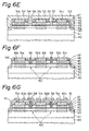
- FIG. 6G a semiconductor device (inverter) having the circuit of Figure 2 and a method of producing the device according to a second embodiment of the present invention are now explained.
- the structure of the semiconductor device of Figure 6G is similar to that of the device of Figure 4G except that two layers 43 and 44 are additional formed on an N-type AlGaAs electron-supply layer 42.
- a feature of this embodiment makes the difference in distance between L 3 and L 4 of Figure 7B larger than that of L 1 and L 2 of the above-mentioned first embodiment without increasing the etching time.
- the semiconductor device of the second embodiment is useful for making the difference of the gate threshold voltage of an enhancement-mode transistor and a depletion-mode transistor large or for decreasing the gate capacitance of both of the transistors by reducing the impurity concentration of both.
- an undoped GaAs channel layer 41 having a thickness of from 0.1 to 0.3 ⁇ m is epitaxially formed on a semi-insulating GaAs substrate 40.
- An N-type AlGaAs electron-supply layer 42 is epitaxially grown on the undoped GaAs layer 41 to form a heterojunction with the GaAs layer 41.
- an N-type GaAs layer 43 and an N-type AlGaAs layer 44 are continuously formed on the AlGaAs layer 42.
- the total thickness of the layers 43 and 44 corresponds to the different (L 4 - L 3 ) between the distances L 3 and L 4 from the heterojunction interface to the bottom of the grooves (i.e., gate electrodes) of the enhancement-mode transistor and the depletion-mode transistor e.g., 10 nm or more.
- the GaAs layer 43 is doped with Si impurities of from 1 x 10 17 to 2 x 10 18 cm -3 and has a thickness of up to 20 nm, e.g., 6 nm.
- the AlGaAs layer 44 is also doped with Si impurities of from 1 x 10 17 to 2 x 10 18 cm -3 and has a thickness of, e.g., 4 nm.
- an N-type GaAs layer 45 is epitaxially grown on the AlGaAs layer 44.
- the GaAs layer 45 has a thickness of, e.g., approximately 100 nm, and is doped with Si impurities of from 1 x 10 17 to 2 x 10 18 cm -3 .
- N -type AlGaAs layer 46 having a thickness equal to that of the AlGaAs layer 46 having a thickness equal to that of the AlGaAs layer 44, e.g. 4 nm, and an N-type GaAs cap-protecting layer 47 are epitaxially formed on the GaAs layer 45.
- the layers 41 to 47 are formed by the MBE method or the MOCVD method.
- the formed layers 41 to 47 are selectively etched by a suitable etching method so as to form an isolated mesa portion 48 in which transistors are formed. Namely, isolation between elements is attained.
- portions of the GaAs layer 47 and the AlGaAs layer 46 corresponding to a gate region of the enhancement-mode transistor are selectively etched to form a recess 49.
- a small portion of the N-type GaAs layer 45 may be etched.
- an insulating material such as Si0 2 is applied on the entire exposed surface to form an insulating protector film 50.
- the film 50 is selectively etched by a lithograph method to form openings for source and drain electrodes.
- the GaAs layer 47, the AlGaAs layer 46, and the GaAs layer 45 are etched through the openings by a suitable etching method.
- Ohmic contact electrodes (i.e., source and drain electrodes) 51a, 51b, and 51c are formed in the openings by depositing metal such as AuGe/Au and patterning the metal layer by,e.g., a lift-off method.
- a heat treatment for alloying is carried out to form alloyed regions 52a, 52b, and 52c coming into ohmic contact with a two-dimensional electron gas layer.
- a resist film 8e.g., a positive photoresist film) 53 is applied on the entire exposed surface and is patterned to form openings 54 and 55 corresponding to gate regions of the transistors.
- the insulating protector film 50 is etched through the openings 54 and 55 with a suitable etchant. Then a groove 56 for the gate electrode of the enhancement-mode transistor and groove 57 for the gate electrode of the depletion-mode transistor are formed by the above-mentioned reactive ion etching method using CCl 2 F 2 gas and He gas.
- FIGS 7A and 7B The progress of the etching depth in the reactive ion etching step is shown in Figures 7A and 7B.
- the slanted lines E and D indicate the grooves for the gate electrodes of the enhancement-mode and depletion-mode transistors, respectively.
- the point R indicates the depth of the recess 49 ( Figure 6C). Since the etching rate of GaAs is much higher than that of AlGaAs, as mentioned in the first embodiment, and the thickness of the AlGaAs layer 46 is equal to that of the AlGaAs layer 42 is almost simultaneous with the formation of the groove 57 at the AlGaAs layer 44. Thereafter the etching proceeds at a very slow rate in both of the AlGaAs layers 42 and 44.
- the grooves 56 and 57 are simultaneously completed so as to attain predetermined distances L 3 and L 4 ( Figure 7B).
- the distances L 3 and L 4 are 43 nm and 53 nm, respectively, and the difference between the distances L 3 and L 4 is 10 nm, corresponding to the total thickness of the layers 43 and 44.
- gate electrodes 58 and 59 are formed in the grooves 56 and 57 by depositing metal such as Ti/Pt/Au and Al and patterning it.
- metal such as Ti/Pt/Au and Al
- the gate electrode 58 of the enhancement-mode transistor and the gate electrode 59 of the depletion-mode transistor are simultaneously completed, and a two-dimensional electron gas 60 is generated in the undoped GaAs layer 41 at the heterojunction between the alloyed regions 52a, 52b, and 52c.
- an insulating film 61 e.g., of SiO - , is deposited on surface and is selectively etched to form contact holes. Then conductor lines 62a, 62b, 62c and 62d are formed by a conventional process. Thus, the inverter comprising enhancement-mode and depletion-mode heterojunction-type field-effect transistors is completed.
- the present invention it is possible to carry out the formation of grooves having different depths for the enhancement-mode transistor and the depletion-mode transistor simultaneously, i.e., by an etching step. Since the bottom of the grooves is an AlGaAs layer in which the etching rate is very slow, the depth of the grooves, i.e., the distance from the heterojunction interface to the bottom of the gate electrodes, can be easily and accurately controlled. Therefore, a good uniformity of the gate threshold voltages of the enhancement-mode and depletion-mode transistors in a substrate (wafer) can be obtained, thereby contributing to an increase in the production yield.
Landscapes
- Junction Field-Effect Transistors (AREA)
Applications Claiming Priority (4)
| Application Number | Priority Date | Filing Date | Title |
|---|---|---|---|
| JP224650/83 | 1983-11-29 | ||
| JP224634/83 | 1983-11-29 | ||
| JP58224634A JPS60116177A (ja) | 1983-11-29 | 1983-11-29 | 半導体装置の製造方法 |
| JP58224650A JPS60116178A (ja) | 1983-11-29 | 1983-11-29 | 半導体装置の製造方法 |
Publications (3)
| Publication Number | Publication Date |
|---|---|
| EP0143656A2 true EP0143656A2 (de) | 1985-06-05 |
| EP0143656A3 EP0143656A3 (en) | 1985-09-25 |
| EP0143656B1 EP0143656B1 (de) | 1989-02-22 |
Family
ID=26526164
Family Applications (1)
| Application Number | Title | Priority Date | Filing Date |
|---|---|---|---|
| EP84308259A Expired EP0143656B1 (de) | 1983-11-29 | 1984-11-28 | Halbleiteranordnung mit Verbindungshalbleiter und Verfahren zu dessen Herstellung |
Country Status (3)
| Country | Link |
|---|---|
| US (2) | US4742379A (de) |
| EP (1) | EP0143656B1 (de) |
| DE (1) | DE3476841D1 (de) |
Cited By (5)
| Publication number | Priority date | Publication date | Assignee | Title |
|---|---|---|---|---|
| EP0175437A1 (de) * | 1984-05-01 | 1986-03-26 | Fujitsu Limited | Herstellung von GaAs-HEMT's des Anreicherungs- und Verarmungstyps |
| EP0206274A1 (de) * | 1985-06-21 | 1986-12-30 | Honeywell Inc. | Komplementäre IC-Struktur mit hoher Steilheit |
| US4837178A (en) * | 1984-10-31 | 1989-06-06 | Fujitsu Limited | Method for producing a semiconductor integrated circuit having an improved isolation structure |
| FR2635918A1 (fr) * | 1988-08-26 | 1990-03-02 | Mitsubishi Electric Corp | Transistor a effet de champ a plusieurs couches de semiconducteur composite |
| EP0940855A3 (de) * | 1998-03-06 | 1999-09-22 | Nec Corporation | Feldeffekttransistor mit III-V Halbleiterheteroübergang |
Families Citing this family (27)
| Publication number | Priority date | Publication date | Assignee | Title |
|---|---|---|---|---|
| EP0143656B1 (de) * | 1983-11-29 | 1989-02-22 | Fujitsu Limited | Halbleiteranordnung mit Verbindungshalbleiter und Verfahren zu dessen Herstellung |
| US4897361A (en) * | 1987-12-14 | 1990-01-30 | American Telephone & Telegraph Company, At&T Bell Laboratories | Patterning method in the manufacture of miniaturized devices |
| US5192701A (en) * | 1988-03-17 | 1993-03-09 | Kabushiki Kaisha Toshiba | Method of manufacturing field effect transistors having different threshold voltages |
| DE68928395T2 (de) * | 1988-06-28 | 1998-05-14 | Nippon Electric Co | Halbleitervorrichtung mit Verbindungshalbleiterfet mit E/D-Struktur mit hoher Geräuschmarge |
| JPH02148740A (ja) * | 1988-11-29 | 1990-06-07 | Fujitsu Ltd | 半導体装置及びその製造方法 |
| US5041393A (en) * | 1988-12-28 | 1991-08-20 | At&T Bell Laboratories | Fabrication of GaAs integrated circuits |
| JPH03229426A (ja) * | 1989-11-29 | 1991-10-11 | Texas Instr Inc <Ti> | 集積回路及びその製造方法 |
| US5585288A (en) * | 1990-07-16 | 1996-12-17 | Raytheon Company | Digital MMIC/analog MMIC structures and process |
| JPH04280436A (ja) * | 1990-09-28 | 1992-10-06 | Motorola Inc | 相補型自己整合hfetの製造方法 |
| JPH04260338A (ja) * | 1991-02-14 | 1992-09-16 | Mitsubishi Electric Corp | 半導体装置の製造方法 |
| US5116774A (en) * | 1991-03-22 | 1992-05-26 | Motorola, Inc. | Heterojunction method and structure |
| KR940007668B1 (ko) * | 1991-12-26 | 1994-08-22 | 재단법인 한국전자통신연구소 | 갈륨비소 금속반도체 전계효과 트랜지스터의 제조방법 |
| US5254492A (en) * | 1992-11-10 | 1993-10-19 | Texas Instruments Incorporated | Method of fabricating an integrated circuit for providing low-noise and high-power microwave operation |
| JPH06204253A (ja) * | 1993-01-07 | 1994-07-22 | Fujitsu Ltd | 電界効果半導体装置 |
| EP0642175B1 (de) * | 1993-09-07 | 2004-04-28 | Murata Manufacturing Co., Ltd. | Halbleiteranordnung mit Schottky-Elektrode und Verfahren zur Herstellung |
| JP3203192B2 (ja) * | 1996-10-16 | 2001-08-27 | 三洋電機株式会社 | 半導体装置およびその製造方法 |
| JPH10326890A (ja) * | 1997-03-21 | 1998-12-08 | Matsushita Electric Ind Co Ltd | 半導体装置及びその製造方法 |
| US6242293B1 (en) | 1998-06-30 | 2001-06-05 | The Whitaker Corporation | Process for fabricating double recess pseudomorphic high electron mobility transistor structures |
| US6060402A (en) * | 1998-07-23 | 2000-05-09 | The Whitaker Corporation | Process for selective recess etching of epitaxial field effect transistors with a novel etch-stop layer |
| US6307221B1 (en) | 1998-11-18 | 2001-10-23 | The Whitaker Corporation | InxGa1-xP etch stop layer for double recess pseudomorphic high electron mobility transistor structures |
| US6703638B2 (en) | 2001-05-21 | 2004-03-09 | Tyco Electronics Corporation | Enhancement and depletion-mode phemt device having two ingap etch-stop layers |
| JP4949628B2 (ja) * | 2002-10-30 | 2012-06-13 | 台湾積體電路製造股▲ふん▼有限公司 | Cmosプロセス中に歪み半導基板層を保護する方法 |
| US7449728B2 (en) * | 2003-11-24 | 2008-11-11 | Tri Quint Semiconductor, Inc. | Monolithic integrated enhancement mode and depletion mode field effect transistors and method of making the same |
| JP2008263146A (ja) * | 2007-04-13 | 2008-10-30 | Matsushita Electric Ind Co Ltd | 半導体装置およびその製造方法 |
| WO2009066434A1 (ja) * | 2007-11-19 | 2009-05-28 | Nec Corporation | 電界効果トランジスタおよびその製造方法 |
| TWI615977B (zh) * | 2013-07-30 | 2018-02-21 | 高效電源轉換公司 | 具有匹配臨界電壓之積體電路及其製造方法 |
| CN109192698B (zh) * | 2018-07-13 | 2020-12-01 | 北京大学深圳研究生院 | 一种基于InGaN插入层实现GaN器件隔离的方法 |
Family Cites Families (9)
| Publication number | Priority date | Publication date | Assignee | Title |
|---|---|---|---|---|
| US4163237A (en) * | 1978-04-24 | 1979-07-31 | Bell Telephone Laboratories, Incorporated | High mobility multilayered heterojunction devices employing modulated doping |
| GB1602498A (en) * | 1978-05-31 | 1981-11-11 | Secr Defence | Fet devices and their fabrication |
| US4325181A (en) * | 1980-12-17 | 1982-04-20 | The United States Of America As Represented By The Secretary Of The Navy | Simplified fabrication method for high-performance FET |
| DE3279795D1 (en) * | 1981-04-23 | 1989-08-03 | Fujitsu Ltd | High electron mobility semiconductor device |
| US4601096A (en) * | 1983-02-15 | 1986-07-22 | Eaton Corporation | Method for fabricating buried channel field effect transistor for microwave and millimeter frequencies utilizing molecular beam epitaxy |
| JPS59168677A (ja) * | 1983-03-14 | 1984-09-22 | Fujitsu Ltd | 半導体装置及びその製造方法 |
| EP0143656B1 (de) * | 1983-11-29 | 1989-02-22 | Fujitsu Limited | Halbleiteranordnung mit Verbindungshalbleiter und Verfahren zu dessen Herstellung |
| JPS613465A (ja) * | 1984-06-18 | 1986-01-09 | Fujitsu Ltd | 半導体装置及びその製造方法 |
| US4746627A (en) * | 1986-10-30 | 1988-05-24 | Mcdonnell Douglas Corporation | Method of making complementary GaAs heterojunction transistors |
-
1984
- 1984-11-28 EP EP84308259A patent/EP0143656B1/de not_active Expired
- 1984-11-28 DE DE8484308259T patent/DE3476841D1/de not_active Expired
- 1984-11-29 US US06/676,359 patent/US4742379A/en not_active Expired - Fee Related
-
1988
- 1988-01-21 US US07/146,664 patent/US4849368A/en not_active Expired - Fee Related
Cited By (8)
| Publication number | Priority date | Publication date | Assignee | Title |
|---|---|---|---|---|
| EP0175437A1 (de) * | 1984-05-01 | 1986-03-26 | Fujitsu Limited | Herstellung von GaAs-HEMT's des Anreicherungs- und Verarmungstyps |
| US4615102A (en) * | 1984-05-01 | 1986-10-07 | Fujitsu Limited | Method of producing enhancement mode and depletion mode FETs |
| US4837178A (en) * | 1984-10-31 | 1989-06-06 | Fujitsu Limited | Method for producing a semiconductor integrated circuit having an improved isolation structure |
| EP0206274A1 (de) * | 1985-06-21 | 1986-12-30 | Honeywell Inc. | Komplementäre IC-Struktur mit hoher Steilheit |
| US4814851A (en) * | 1985-06-21 | 1989-03-21 | Honeywell Inc. | High transconductance complementary (Al,Ga)As/gas heterostructure insulated gate field-effect transistor |
| FR2635918A1 (fr) * | 1988-08-26 | 1990-03-02 | Mitsubishi Electric Corp | Transistor a effet de champ a plusieurs couches de semiconducteur composite |
| EP0940855A3 (de) * | 1998-03-06 | 1999-09-22 | Nec Corporation | Feldeffekttransistor mit III-V Halbleiterheteroübergang |
| US6624440B2 (en) | 1998-03-06 | 2003-09-23 | Nec Corporation | Field effect transistor |
Also Published As
| Publication number | Publication date |
|---|---|
| EP0143656A3 (en) | 1985-09-25 |
| EP0143656B1 (de) | 1989-02-22 |
| US4742379A (en) | 1988-05-03 |
| US4849368A (en) | 1989-07-18 |
| DE3476841D1 (en) | 1989-03-30 |
Similar Documents
| Publication | Publication Date | Title |
|---|---|---|
| EP0143656B1 (de) | Halbleiteranordnung mit Verbindungshalbleiter und Verfahren zu dessen Herstellung | |
| EP0119089B1 (de) | Halbleiteranordnung mit GaAs und Verfahren zu dessen Herstellung | |
| KR890004456B1 (ko) | 반도체장치의 제조방법 | |
| US5302840A (en) | HEMT type semiconductor device having two semiconductor well layers | |
| EP0551110B1 (de) | Verbindungshalbleiterbauelemente | |
| WO1989007333A1 (en) | Vertical transistor device fabricated with semiconductor regrowth | |
| US4389768A (en) | Self-aligned process for fabricating gallium arsenide metal-semiconductor field effect transistors | |
| US4503600A (en) | Process for manufacturing a buried gate field effect transistor | |
| US5336626A (en) | Method of manufacturing a MESFET with an epitaxial void | |
| US5334865A (en) | MODFET structure for threshold control | |
| US5225703A (en) | Dual field effect transistor structure employing a single source region | |
| US4929985A (en) | Compound semiconductor device | |
| JP2630446B2 (ja) | 半導体装置及びその製造方法 | |
| US5702975A (en) | Method for isolating semiconductor device | |
| JPH05259193A (ja) | 半導体装置 | |
| US5219772A (en) | Method for making field effect devices with ultra-short gates | |
| JP2685026B2 (ja) | 電界効果トランジスタおよび製造方法 | |
| US5483089A (en) | Electrically isolated MESFET | |
| KR890003416B1 (ko) | 반도체 장치 및 그의 제조방법 | |
| JP2701583B2 (ja) | トンネルトランジスタ及びその製造方法 | |
| GB2217108A (en) | Semiconductor device etching using indium containing etch stop | |
| JPS60251671A (ja) | 電界効果形トランジスタおよびその製造方法 | |
| JP2526492B2 (ja) | 半導体装置の製造方法 | |
| CA1196111A (en) | Ingaas field effect transistor | |
| JP2541240B2 (ja) | 半導体装置 |
Legal Events
| Date | Code | Title | Description |
|---|---|---|---|
| PUAI | Public reference made under article 153(3) epc to a published international application that has entered the european phase |
Free format text: ORIGINAL CODE: 0009012 |
|
| AK | Designated contracting states |
Designated state(s): DE FR GB |
|
| PUAL | Search report despatched |
Free format text: ORIGINAL CODE: 0009013 |
|
| RHK1 | Main classification (correction) |
Ipc: H01L 21/306 |
|
| AK | Designated contracting states |
Designated state(s): DE FR GB |
|
| 17P | Request for examination filed |
Effective date: 19860218 |
|
| 17Q | First examination report despatched |
Effective date: 19880322 |
|
| GRAA | (expected) grant |
Free format text: ORIGINAL CODE: 0009210 |
|
| AK | Designated contracting states |
Kind code of ref document: B1 Designated state(s): DE FR GB |
|
| REF | Corresponds to: |
Ref document number: 3476841 Country of ref document: DE Date of ref document: 19890330 |
|
| ET | Fr: translation filed | ||
| PLBE | No opposition filed within time limit |
Free format text: ORIGINAL CODE: 0009261 |
|
| STAA | Information on the status of an ep patent application or granted ep patent |
Free format text: STATUS: NO OPPOSITION FILED WITHIN TIME LIMIT |
|
| 26N | No opposition filed | ||
| PGFP | Annual fee paid to national office [announced via postgrant information from national office to epo] |
Ref country code: FR Payment date: 19981110 Year of fee payment: 15 |
|
| PGFP | Annual fee paid to national office [announced via postgrant information from national office to epo] |
Ref country code: GB Payment date: 19981204 Year of fee payment: 15 |
|
| PGFP | Annual fee paid to national office [announced via postgrant information from national office to epo] |
Ref country code: DE Payment date: 19981207 Year of fee payment: 15 |
|
| PG25 | Lapsed in a contracting state [announced via postgrant information from national office to epo] |
Ref country code: GB Free format text: LAPSE BECAUSE OF NON-PAYMENT OF DUE FEES Effective date: 19991128 |
|
| GBPC | Gb: european patent ceased through non-payment of renewal fee |
Effective date: 19991128 |
|
| PG25 | Lapsed in a contracting state [announced via postgrant information from national office to epo] |
Ref country code: FR Free format text: LAPSE BECAUSE OF NON-PAYMENT OF DUE FEES Effective date: 20000731 |
|
| PG25 | Lapsed in a contracting state [announced via postgrant information from national office to epo] |
Ref country code: DE Free format text: LAPSE BECAUSE OF NON-PAYMENT OF DUE FEES Effective date: 20000901 |
|
| REG | Reference to a national code |
Ref country code: FR Ref legal event code: ST |