EP0145787A1 - Dispositif de commande du suivi de piste d'un dispositif reproducteur de disques enregistres - Google Patents
Dispositif de commande du suivi de piste d'un dispositif reproducteur de disques enregistres Download PDFInfo
- Publication number
- EP0145787A1 EP0145787A1 EP84900885A EP84900885A EP0145787A1 EP 0145787 A1 EP0145787 A1 EP 0145787A1 EP 84900885 A EP84900885 A EP 84900885A EP 84900885 A EP84900885 A EP 84900885A EP 0145787 A1 EP0145787 A1 EP 0145787A1
- Authority
- EP
- European Patent Office
- Prior art keywords
- tracking
- pickup
- tracking control
- disc
- pickup means
- Prior art date
- Legal status (The legal status is an assumption and is not a legal conclusion. Google has not performed a legal analysis and makes no representation as to the accuracy of the status listed.)
- Granted
Links
Images



Classifications
-
- G—PHYSICS
- G11—INFORMATION STORAGE
- G11B—INFORMATION STORAGE BASED ON RELATIVE MOVEMENT BETWEEN RECORD CARRIER AND TRANSDUCER
- G11B7/00—Recording or reproducing by optical means, e.g. recording using a thermal beam of optical radiation by modifying optical properties or the physical structure, reproducing using an optical beam at lower power by sensing optical properties; Record carriers therefor
- G11B7/08—Disposition or mounting of heads or light sources relatively to record carriers
- G11B7/09—Disposition or mounting of heads or light sources relatively to record carriers with provision for moving the light beam or focus plane for the purpose of maintaining alignment of the light beam relative to the record carrier during transducing operation, e.g. to compensate for surface irregularities of the latter or for track following
-
- G—PHYSICS
- G11—INFORMATION STORAGE
- G11B—INFORMATION STORAGE BASED ON RELATIVE MOVEMENT BETWEEN RECORD CARRIER AND TRANSDUCER
- G11B21/00—Head arrangements not specific to the method of recording or reproducing
- G11B21/02—Driving or moving of heads
- G11B21/10—Track finding or aligning by moving the head ; Provisions for maintaining alignment of the head relative to the track during transducing operation, i.e. track following
- G11B21/106—Track finding or aligning by moving the head ; Provisions for maintaining alignment of the head relative to the track during transducing operation, i.e. track following on disks
-
- G—PHYSICS
- G11—INFORMATION STORAGE
- G11B—INFORMATION STORAGE BASED ON RELATIVE MOVEMENT BETWEEN RECORD CARRIER AND TRANSDUCER
- G11B7/00—Recording or reproducing by optical means, e.g. recording using a thermal beam of optical radiation by modifying optical properties or the physical structure, reproducing using an optical beam at lower power by sensing optical properties; Record carriers therefor
- G11B7/08—Disposition or mounting of heads or light sources relatively to record carriers
- G11B7/09—Disposition or mounting of heads or light sources relatively to record carriers with provision for moving the light beam or focus plane for the purpose of maintaining alignment of the light beam relative to the record carrier during transducing operation, e.g. to compensate for surface irregularities of the latter or for track following
- G11B7/0946—Disposition or mounting of heads or light sources relatively to record carriers with provision for moving the light beam or focus plane for the purpose of maintaining alignment of the light beam relative to the record carrier during transducing operation, e.g. to compensate for surface irregularities of the latter or for track following specially adapted for operation during external perturbations not related to the carrier or servo beam, e.g. vibration
Definitions
- This invention relates to tracking control apparatus for recording disc reproducing apparatus which reproduces successively recorded information by way of a pickup means from a disc-like recording medium (which will be referred to as a disc hereinbelow) rotated and driven, and the above-mentioned pickup means is scanned with satisfactory tracking along an information track on a disc, while the tracking characteristic is maintained stably irrespective of the application of external impact.
- a pickup means from a disc-like recording medium (which will be referred to as a disc hereinbelow) rotated and driven, and the above-mentioned pickup means is scanned with satisfactory tracking along an information track on a disc, while the tracking characteristic is maintained stably irrespective of the application of external impact.
- Fig. 1 is an explanatory diagram for the principle of a servo system using three beams, which is a system of tracking servo for an optical disc used for obtaining a reproduced signal by way of a light beam.
- the references T , T 2 and T 3 are information tracks of a disc; 2, a light beam for reading; and 1 and 3, auxiliary beams for detecting tracking signal, and the difference between reproduced outputs of the auxiliary beams 1 and 3 is detected using a differential amplifier so as to obtain a tracking signal 4 shown in Fig. 1.
- the tracking signal 4 shown in Fig. 1 is obtained.
- a range "A" within the tracking signal 4 indicates that the beams 1, 2 and 3 are scanning the track T 2
- a range "B" indicates that a portion between the tracks T 1 and T 2 is being scanned.
- Fig. 2 is a structural diagram of the tracking servo.
- the reference 10 is a disc; 11, a motor for rotating the disc 10; 12, a reading lens; 13, a light source used so that the disc 10 is irradiated by auxiliary beams 1, 2, 3 for tracking as shown in Fig. 1 using a diffraction grating 14.
- the reference 15 is a beam splitter; 16, a tracking mirror, and these elements are used for controlling the position of the light beam so that the reading light beam, which is focussed on the disc 10 by way of the reading lens 12, is always on a track.
- the references 17 and 18 are photo detectors for receiving reproduced outputs of the auxiliary beams 1 and 3 shown in Fig. 1, and the tracking signal 4 of Fig.
- the reference 20 is an equalizer which is a filter for correcting the characteristic of the tracking servo system.
- the reference 21 is a D.C. amplifier which supplies a current corresponding to the output from the equalizer 20 so as to effect tracking control with the deflecting angle of the tracking mirror 16 being controlled.
- the eccentricity of the disc 10 has a harmonic component of a fundamental wave of 30Hz, and therefore, the tracking mirror 16 has to be operated so as to scan an information track of the disc 10 by the reading light beam 2 of Fig. 1 by tracking the eccentricity.
- the band of tracking servo is required to cover all the harmonic components of the above-mentioned eccentricity. For instant, assuming that 30Hz component of eccentricity is 100 micron and lkHz componet is 2 micron, the reading light beam 2 has to follow the information track of the disc 10 with an accuracy of +0.1 micron.
- Fig. 3 illustrates a block diagram of the tracking servo system described with reference to Fig. 2.
- the reference R is a signal indicative of the position of an information track of the disc;
- the reference C a signal indicative of the position of the reading light beam, and the difference between these signals becomes an error signal E, and therefore, the tracking servo system can be expressed as a servo system in which the tracking mirror G3 is controlled through the equalizer Gl and the D.C. amplifier G2.
- Gl, G2 and G3 respectively indicate transfer functions.
- the reference SW is a switch which is arranged to cut the signal C temporarily for the description of malfunction.
- Fig. 4a shows a frequency response of the above-mentioned equalizer and tracking mirror Gl, G3 and it is assumed that the frequency response of the DC amplifier G2 is flat for simplicity.
- Fig. 4b shows open-loop characteristic of the block diagram shown in Fig. 3, and the reference Kl indicates the open-loop gain.
- the region A is a dynamic range of the tracking servo, in which the reading beam can be held on the track T2, while the region B is an unstable range in which the polarity of the tracking servo is inverted. Therefore, if the size of the defect 6 is larger than tl, t2, the reading beam is off the track as indicated by the arrows 7 and 8. If the size of the defect 6 is smaller the same, then the reading beam is again held on T2.
- the present invention has been developed in view of the above, and contemplates to provide a reproduce pickup and a tracking servo which are stable against information track defects of discs, and sufficiently stable against disturbance, such as vibrations, applied to a disc player.
- the reproduce apparatus comprises pickup means for reproducing information signals from information tracks on a disc which is rotated and driven; means for producing a tracking control signal corresponding to the relative position between the pickup means and said information track; pickup drive means for moving said pickup means in accordance with said tracking control signal; means for detecting an output corresponding to the displacement of said pickup; and means for feading back a detected output corresponding to said displacement to said pickup drive means.
- Fig. 1 is a diagram showing the relationship between the irradiating points of light beams applied to an information track and a tracking control signal
- Fig. 2 is a block diagram showing a fundamental structure of a conventional tracking control apparatus
- Fig. 3 is a block diagram for the description of the operation of the same
- Figs. 4 a and b are characteristic diagrams for the description of the operation of the same
- Fig. 5 is a top plan view for the description of tracking condition
- Fig. 6 is a block diagram showing a fundamental structure of the tracking control apparatus according to the present invention
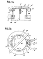
- Fig. 7 a is a side cross-sectional view of a main part of the same, and b is a partial plan view of the same
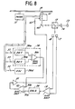
- Fig. 8 is a block diagram of an embodiment of the tracking control apparatus according to the present invention.
- Fig. 6 shows a structual diagram of an embodiment of the present invention. Blocks in Fig. 2 having the same designating references are the same as those in Fig. 2.
- the reference 30 is an angle detecting device for detecting an angle of a tracking mirror 16, which angle detecting device 30 supplies a voltage corresponding to a swing angle of the tracking mirror 16 to a second differential amplifier 32.
- An output of a first differential amplifier 19 is inputted via an equalizer 20 to the above-mentioned second differential amplifier 32 whose output is fed via a drive amplifier 31 to the tracking mirror 16.
- reflected light of the tracking light beams which are designated at 1 and 3 in Fig. 1, from the disc is applied to photo detectors 17 and 18 so that a tracking signal is obtained at the output of the first differential amplifier 19.
- the tracking signal is inputted to one input terminal 32a of the second differential amplifier 32 after response characteristic of tracking servo is corrected by way of an equalizer 20.
- the tracking signal fed to the second differential amplifier 32 is fed via the drive amplifier 31 so as to drive and control the tracking mirror 16.
- the swing angle of the tracking mirror 16 is detected by the angle detector 30, and is inputted to the other input terminal 32b of the second differential amplifier 32.
- the open-loop gain of the position servo system is suitably set so as to prevent malfunction caused from the above-mentioned disturbance.
- Fig. 7 shows a pickup assembly including the read lens 12 and the tracking mirror 16 of Fig. 6.
- the reference 41 is a read lens attached to an optical tube 40 which moves in a direction of A along a supporting shaft 42 due to the action between an annular magnetic circuit 46 and a coil 44 so that an output light beam from the read lens 41 is focussed on the disc.
- the optical tube 40 rotates in a direction of an arrow B due to the action of a magnetic circuit 47 with a current being fed to a coil 45. Therefore, the read lens 41 is also rotated in the direction of the arrow B so that the output light beam from the read lens 41 is applied on the information track of the disc.
- the reference 43 is a supporting plate which supports the supporting shaft 42 at a predetermined position allowing the optical tube 40 to slide in the direction of the arrow A along the supporting shaft 42 and also to rotate in the direction B.
- the reference 49 is a magnetic sheet provided at a portion of a side wall of the optical tube 40
- the reference 50 is a magnetic circuit for detecting a rotational position.
- Fig. 8 shows a block diagram of an embodiment of the present invention.
- Fig. 8 corresponds to Fig. 6, and output light from the beam splitter 15 is applied via a fixed mirror 16F to the read lens 41 to be incident on the track of the disc 10. Reflected light from the disc 10 is incident via the fixed mirror 16F, and the beam splitter 15 on the photo detectors 17 and 18, so that the first differential amplifier 19 receives inputs to perform the above-described tracking servo operation.
- To the coil 52 shown in Fig. 7 is applied a current of 50kHz or so from an oscillator 30d, and voltages are induced across the coils 51 and 53 where respective outputs are converted into d.c. voltages by way of detectors 30a and 30b, which d.c.
- the angle detector 30 is formed of the 30a, 30b and 30c.
- An output from the differential amplifier 30c is inputted to the second differential amplifier 32, and is then fed via the amplifier 31 to a tracking drive coil 45.
- the tracking error signal from the first differential amplifier 19 is inputted via the equalizer 20 to the second differential amplifier 32.
- the voltage at 32b changes so as to be always equal to the tracking error signal at 32a, and the voltage at 32a substantially equals the voltage at 32b during operation of the tracking servo.
- a magnetic circuit has been used as an element for detecting a position in a tracking direction in the present embodiment, it is possible to optically detect the same, and furthermore pickup devices of any type can be applied as long as it is possible to detect displacement in a tracking direction.
- the magnetic circuit 50 for detecting the position in tracking direction shown in Fig. 7 is arranged so that displacement in the direction of the arrow B can be detected without error even if the optical tube 40 is moved in the direction of the arrow A, and the magnetic substance 49 is always exists within an operating range with respect to the magnetic circuit 50.
- the tracking apparatus of the present invention since a reproducing apparatus which is hardly affected by disturbance, such as vibrations, can be actualized with the gain crossover frequency of the tracking servo system being maintained low, it is possible to actualize a reproducing apparatus of a disc-like recording medium, which operates with stabitlity at a place where vibrations occur, as in automobiles.
Landscapes
- Optical Recording Or Reproduction (AREA)
- Moving Of The Head To Find And Align With The Track (AREA)
Abstract
Applications Claiming Priority (2)
| Application Number | Priority Date | Filing Date | Title |
|---|---|---|---|
| JP58027912A JPS59154677A (ja) | 1983-02-22 | 1983-02-22 | トラツキング制御装置 |
| JP27912/83 | 1983-02-22 |
Publications (3)
| Publication Number | Publication Date |
|---|---|
| EP0145787A1 true EP0145787A1 (fr) | 1985-06-26 |
| EP0145787A4 EP0145787A4 (fr) | 1987-02-12 |
| EP0145787B1 EP0145787B1 (fr) | 1991-11-27 |
Family
ID=12234092
Family Applications (1)
| Application Number | Title | Priority Date | Filing Date |
|---|---|---|---|
| EP84900885A Expired EP0145787B1 (fr) | 1983-02-22 | 1984-02-22 | Dispositif de commande du suivi de piste d'un dispositif reproducteur de disques enregistres |
Country Status (5)
| Country | Link |
|---|---|
| US (1) | US4799206A (fr) |
| EP (1) | EP0145787B1 (fr) |
| JP (1) | JPS59154677A (fr) |
| DE (1) | DE3485307D1 (fr) |
| WO (1) | WO1984003387A1 (fr) |
Families Citing this family (9)
| Publication number | Priority date | Publication date | Assignee | Title |
|---|---|---|---|---|
| JPS60675A (ja) * | 1983-05-19 | 1985-01-05 | Nippon Columbia Co Ltd | ピツクアツプサ−ボ装置 |
| NL8501665A (nl) * | 1985-06-10 | 1987-01-02 | Philips Nv | Optische aftasteenheid met positie- en standdetektiestelsel voor een elektromagnetisch gelagerd objektief. |
| JP2734562B2 (ja) * | 1988-10-13 | 1998-03-30 | 松下電器産業株式会社 | トラッキングサーボの方法 |
| JP2861457B2 (ja) * | 1990-05-24 | 1999-02-24 | セイコーエプソン株式会社 | 光学式記録再生装置 |
| US5446712A (en) * | 1991-04-22 | 1995-08-29 | Seiko Epson Corporation | Optical system having a precision angular displacement mechanism including a flat metal spring |
| US5517474A (en) * | 1993-03-02 | 1996-05-14 | Matsushita Electric Industrial Co., Ltd. | Tracking controller for correcting a tracking error offset |
| US7522480B2 (en) | 2001-01-25 | 2009-04-21 | Dphi Acquisitions, Inc. | Digital tracking servo system with multi-track seek with an acceleration clamp |
| US6862088B2 (en) * | 2001-12-07 | 2005-03-01 | Zoran Corporation | Method and apparatus for providing adaptive control of track servo |
| US7054240B2 (en) * | 2002-03-04 | 2006-05-30 | Zoran Corporation | Method and apparatus for providing focus control on a multi layer disc |
Family Cites Families (24)
| Publication number | Priority date | Publication date | Assignee | Title |
|---|---|---|---|---|
| GB588677A (en) * | 1945-02-12 | 1947-05-30 | Siemens Brothers & Co Ltd | Electrical arrangements for measuring small movements |
| US3924268A (en) * | 1974-08-05 | 1975-12-02 | Ibm | High density track follower control system for magnetic disk file |
| NL174609C (nl) * | 1975-10-15 | 1984-07-02 | Philips Nv | Volgspiegelinrichting in een optische platenspeler. |
| NL7703232A (nl) * | 1977-03-25 | 1978-09-27 | Philips Nv | Optische aftastinrichting. |
| NL7810386A (nl) * | 1978-10-17 | 1980-04-21 | Philips Nv | Optische leesinrichting voor het uitlezen van een schijfvormige registratiedrager. |
| JPS6215864Y2 (fr) * | 1980-08-04 | 1987-04-22 | ||
| NL8005633A (nl) * | 1980-10-13 | 1982-05-03 | Philips Nv | Inrichting voor het uitlezen en/of inschrijven van een optisch uitleesbare informatiestruktuur. |
| JPS57122029A (en) * | 1981-01-22 | 1982-07-29 | Nippon Kasei Kk | Preparation of formose |
| JPS57122029U (fr) * | 1981-01-23 | 1982-07-29 | ||
| JPS57147143A (en) * | 1981-03-07 | 1982-09-10 | Olympus Optical Co Ltd | Objective lens driving device |
| NL8101669A (nl) * | 1981-04-03 | 1982-11-01 | Philips Nv | Inrichting voor het detekteren van de stand van een voorwerp. |
| JPS57191840A (en) * | 1981-05-20 | 1982-11-25 | Mitsubishi Electric Corp | Track follow-up controller |
| JPS57210456A (en) * | 1981-06-22 | 1982-12-24 | Sony Corp | Objective lens device |
| NL8103305A (nl) * | 1981-07-10 | 1983-02-01 | Philips Nv | Opto-elektronische inrichting voor het met een stralingsbundel inschrijven en/of uitlezen van registratiesporen. |
| JPS5873023A (ja) * | 1981-10-27 | 1983-05-02 | Pioneer Electronic Corp | 情報読取装置におけるトラツキングサ−ボ信号発生装置 |
| US4556964A (en) * | 1981-12-21 | 1985-12-03 | Burroughs Corporation | Technique for monitoring galvo angle |
| US4489406A (en) * | 1982-02-17 | 1984-12-18 | Burroughs Corporation | Optical memory system having a short seek capability |
| JPS58159248A (ja) * | 1982-03-17 | 1983-09-21 | Fujitsu Ltd | 光デイスク装置のトラツキングサ−ボ方式 |
| JPS58224472A (ja) * | 1982-06-22 | 1983-12-26 | Ricoh Co Ltd | 回転デイスクの記録再生ヘツド移送装置 |
| JPS59104735A (ja) * | 1982-12-08 | 1984-06-16 | Sony Corp | 対物レンズ駆動装置 |
| JPS59116972A (ja) * | 1982-12-23 | 1984-07-06 | Olympus Optical Co Ltd | 光学式記録再生装置用トラッキング装置の異常状態処理装置 |
| US4566089A (en) * | 1983-03-30 | 1986-01-21 | Mitsubishi Denki Kabushiki Kaisha | Deviation correction apparatus for optical disc light beams |
| JPS6095733A (ja) * | 1983-10-31 | 1985-05-29 | Hitachi Ltd | 光学的信号処理装置 |
| EP0518124B1 (fr) * | 1991-06-09 | 1995-09-06 | Krohne AG | Débitmètre massique Coriolis |
-
1983
- 1983-02-22 JP JP58027912A patent/JPS59154677A/ja active Granted
-
1984
- 1984-02-22 US US06/667,485 patent/US4799206A/en not_active Expired - Lifetime
- 1984-02-22 DE DE8484900885T patent/DE3485307D1/de not_active Expired - Lifetime
- 1984-02-22 EP EP84900885A patent/EP0145787B1/fr not_active Expired
- 1984-02-22 WO PCT/JP1984/000065 patent/WO1984003387A1/fr not_active Ceased
Also Published As
| Publication number | Publication date |
|---|---|
| DE3485307D1 (de) | 1992-01-09 |
| JPS59154677A (ja) | 1984-09-03 |
| EP0145787B1 (fr) | 1991-11-27 |
| EP0145787A4 (fr) | 1987-02-12 |
| JPH0519229B2 (fr) | 1993-03-16 |
| US4799206A (en) | 1989-01-17 |
| WO1984003387A1 (fr) | 1984-08-30 |
Similar Documents
| Publication | Publication Date | Title |
|---|---|---|
| US3829622A (en) | Video disc player with variably biased pneumatic head | |
| EP0164642B1 (fr) | Appareil d'enregistrement et de reproduction | |
| US4809247A (en) | Video disc head tracking apparatus | |
| US4236105A (en) | Digital center tracking system | |
| US4703467A (en) | Video disc read back scanner | |
| JPS6233342A (ja) | 光学的情報記録再生装置 | |
| KR950010419B1 (ko) | 코스 액추에이터 트랙킹 신호 발생 장치 | |
| KR940003551B1 (ko) | 광 디스크장치의 트랙 액세스 제어회로 | |
| US4799206A (en) | Tracking control apparatus for recording disc reproducing apparatus | |
| JP2804118B2 (ja) | トラッキング制御装置 | |
| US6233210B1 (en) | Optical drive error tracking method and apparatus | |
| JP3582851B2 (ja) | トラッキング制御装置 | |
| JPH01263978A (ja) | 情報トラックの検索装置 | |
| US5606542A (en) | Optical pickup using three beam tracking method | |
| JPH0612595B2 (ja) | 制御装置 | |
| JPH0743900B2 (ja) | トラツキング制御装置 | |
| JP2003248942A (ja) | 光ディスク装置 | |
| JP2697438B2 (ja) | トラック誤差信号の補正装置 | |
| JPH0770068B2 (ja) | 光学式情報記録再生装置 | |
| JPH0414432B2 (fr) | ||
| JPH1021566A (ja) | トラッキングサーボ装置 | |
| JP2721241B2 (ja) | 光学的情報記録再生装置 | |
| JP2579763B2 (ja) | トラツキング制御装置 | |
| JPH07182664A (ja) | 光ピックアップとその対物レンズ位置検出方法 | |
| JPH01220231A (ja) | トラッキングサーボのゲイン調整装置 |
Legal Events
| Date | Code | Title | Description |
|---|---|---|---|
| PUAI | Public reference made under article 153(3) epc to a published international application that has entered the european phase |
Free format text: ORIGINAL CODE: 0009012 |
|
| 17P | Request for examination filed |
Effective date: 19850103 |
|
| AK | Designated contracting states |
Designated state(s): DE FR GB |
|
| A4 | Supplementary search report drawn up and despatched |
Effective date: 19870212 |
|
| 17Q | First examination report despatched |
Effective date: 19880707 |
|
| GRAA | (expected) grant |
Free format text: ORIGINAL CODE: 0009210 |
|
| AK | Designated contracting states |
Kind code of ref document: B1 Designated state(s): DE FR GB |
|
| ET | Fr: translation filed | ||
| REF | Corresponds to: |
Ref document number: 3485307 Country of ref document: DE Date of ref document: 19920109 |
|
| PLBE | No opposition filed within time limit |
Free format text: ORIGINAL CODE: 0009261 |
|
| STAA | Information on the status of an ep patent application or granted ep patent |
Free format text: STATUS: NO OPPOSITION FILED WITHIN TIME LIMIT |
|
| 26N | No opposition filed | ||
| REG | Reference to a national code |
Ref country code: GB Ref legal event code: 746 Effective date: 19950224 |
|
| REG | Reference to a national code |
Ref country code: FR Ref legal event code: D6 |
|
| REG | Reference to a national code |
Ref country code: GB Ref legal event code: IF02 |
|
| PGFP | Annual fee paid to national office [announced via postgrant information from national office to epo] |
Ref country code: FR Payment date: 20020212 Year of fee payment: 19 |
|
| PGFP | Annual fee paid to national office [announced via postgrant information from national office to epo] |
Ref country code: GB Payment date: 20020220 Year of fee payment: 19 |
|
| PGFP | Annual fee paid to national office [announced via postgrant information from national office to epo] |
Ref country code: DE Payment date: 20020306 Year of fee payment: 19 |
|
| PG25 | Lapsed in a contracting state [announced via postgrant information from national office to epo] |
Ref country code: GB Free format text: LAPSE BECAUSE OF NON-PAYMENT OF DUE FEES Effective date: 20030222 |
|
| PG25 | Lapsed in a contracting state [announced via postgrant information from national office to epo] |
Ref country code: DE Free format text: LAPSE BECAUSE OF NON-PAYMENT OF DUE FEES Effective date: 20030902 |
|
| GBPC | Gb: european patent ceased through non-payment of renewal fee | ||
| PG25 | Lapsed in a contracting state [announced via postgrant information from national office to epo] |
Ref country code: FR Free format text: LAPSE BECAUSE OF NON-PAYMENT OF DUE FEES Effective date: 20031031 |
|
| REG | Reference to a national code |
Ref country code: FR Ref legal event code: ST |