EP0151421B1 - Système de commande pour suspension de véhicule à caractéristiques d'amortissement sensibles aux conditions routières - Google Patents
Système de commande pour suspension de véhicule à caractéristiques d'amortissement sensibles aux conditions routières Download PDFInfo
- Publication number
- EP0151421B1 EP0151421B1 EP85100527A EP85100527A EP0151421B1 EP 0151421 B1 EP0151421 B1 EP 0151421B1 EP 85100527 A EP85100527 A EP 85100527A EP 85100527 A EP85100527 A EP 85100527A EP 0151421 B1 EP0151421 B1 EP 0151421B1
- Authority
- EP
- European Patent Office
- Prior art keywords
- signal
- comparator
- control system
- sensor
- suspension control
- Prior art date
- Legal status (The legal status is an assumption and is not a legal conclusion. Google has not performed a legal analysis and makes no representation as to the accuracy of the status listed.)
- Expired
Links
- 239000000725 suspension Substances 0.000 title claims description 80
- 238000013016 damping Methods 0.000 title claims description 55
- 230000001419 dependent effect Effects 0.000 title description 4
- 239000012530 fluid Substances 0.000 claims description 90
- 230000035939 shock Effects 0.000 claims description 62
- 239000006096 absorbing agent Substances 0.000 claims description 60
- 238000006073 displacement reaction Methods 0.000 claims description 16
- 230000004044 response Effects 0.000 claims description 9
- 230000005540 biological transmission Effects 0.000 claims description 2
- 230000001939 inductive effect Effects 0.000 claims 2
- 238000004891 communication Methods 0.000 description 15
- 238000010586 diagram Methods 0.000 description 14
- 230000004048 modification Effects 0.000 description 14
- 238000012986 modification Methods 0.000 description 14
- 230000033001 locomotion Effects 0.000 description 10
- 230000007246 mechanism Effects 0.000 description 10
- 238000009499 grossing Methods 0.000 description 9
- 238000005096 rolling process Methods 0.000 description 5
- 239000012212 insulator Substances 0.000 description 4
- 239000000428 dust Substances 0.000 description 3
- WABPQHHGFIMREM-UHFFFAOYSA-N lead(0) Chemical compound [Pb] WABPQHHGFIMREM-UHFFFAOYSA-N 0.000 description 3
- 239000011295 pitch Substances 0.000 description 3
- 230000000712 assembly Effects 0.000 description 2
- 238000000429 assembly Methods 0.000 description 2
- 230000008859 change Effects 0.000 description 2
- 230000006835 compression Effects 0.000 description 2
- 238000007906 compression Methods 0.000 description 2
- 230000006698 induction Effects 0.000 description 2
- 238000012544 monitoring process Methods 0.000 description 2
- 230000009467 reduction Effects 0.000 description 2
- 239000003381 stabilizer Substances 0.000 description 2
- 230000001629 suppression Effects 0.000 description 2
- 230000001133 acceleration Effects 0.000 description 1
- 230000006399 behavior Effects 0.000 description 1
- 230000000903 blocking effect Effects 0.000 description 1
- 238000010276 construction Methods 0.000 description 1
- 230000003247 decreasing effect Effects 0.000 description 1
- 238000001514 detection method Methods 0.000 description 1
- 230000000694 effects Effects 0.000 description 1
- 238000001914 filtration Methods 0.000 description 1
- 230000006870 function Effects 0.000 description 1
- 239000011796 hollow space material Substances 0.000 description 1
- 230000000630 rising effect Effects 0.000 description 1
- 238000007789 sealing Methods 0.000 description 1
- 230000035945 sensitivity Effects 0.000 description 1
- 238000007493 shaping process Methods 0.000 description 1
- 230000003068 static effect Effects 0.000 description 1
- 230000001960 triggered effect Effects 0.000 description 1
Images






Classifications
-
- G—PHYSICS
- G01—MEASURING; TESTING
- G01S—RADIO DIRECTION-FINDING; RADIO NAVIGATION; DETERMINING DISTANCE OR VELOCITY BY USE OF RADIO WAVES; LOCATING OR PRESENCE-DETECTING BY USE OF THE REFLECTION OR RERADIATION OF RADIO WAVES; ANALOGOUS ARRANGEMENTS USING OTHER WAVES
- G01S15/00—Systems using the reflection or reradiation of acoustic waves, e.g. sonar systems
- G01S15/88—Sonar systems specially adapted for specific applications
-
- B—PERFORMING OPERATIONS; TRANSPORTING
- B60—VEHICLES IN GENERAL
- B60G—VEHICLE SUSPENSION ARRANGEMENTS
- B60G17/00—Resilient suspensions having means for adjusting the spring or vibration-damper characteristics, for regulating the distance between a supporting surface and a sprung part of vehicle or for locking suspension during use to meet varying vehicular or surface conditions, e.g. due to speed or load
- B60G17/015—Resilient suspensions having means for adjusting the spring or vibration-damper characteristics, for regulating the distance between a supporting surface and a sprung part of vehicle or for locking suspension during use to meet varying vehicular or surface conditions, e.g. due to speed or load the regulating means comprising electric or electronic elements
- B60G17/016—Resilient suspensions having means for adjusting the spring or vibration-damper characteristics, for regulating the distance between a supporting surface and a sprung part of vehicle or for locking suspension during use to meet varying vehicular or surface conditions, e.g. due to speed or load the regulating means comprising electric or electronic elements characterised by their responsiveness, when the vehicle is travelling, to specific motion, a specific condition, or driver input
- B60G17/0165—Resilient suspensions having means for adjusting the spring or vibration-damper characteristics, for regulating the distance between a supporting surface and a sprung part of vehicle or for locking suspension during use to meet varying vehicular or surface conditions, e.g. due to speed or load the regulating means comprising electric or electronic elements characterised by their responsiveness, when the vehicle is travelling, to specific motion, a specific condition, or driver input to an external condition, e.g. rough road surface, side wind
-
- B—PERFORMING OPERATIONS; TRANSPORTING
- B60—VEHICLES IN GENERAL
- B60G—VEHICLE SUSPENSION ARRANGEMENTS
- B60G17/00—Resilient suspensions having means for adjusting the spring or vibration-damper characteristics, for regulating the distance between a supporting surface and a sprung part of vehicle or for locking suspension during use to meet varying vehicular or surface conditions, e.g. due to speed or load
- B60G17/015—Resilient suspensions having means for adjusting the spring or vibration-damper characteristics, for regulating the distance between a supporting surface and a sprung part of vehicle or for locking suspension during use to meet varying vehicular or surface conditions, e.g. due to speed or load the regulating means comprising electric or electronic elements
- B60G17/019—Resilient suspensions having means for adjusting the spring or vibration-damper characteristics, for regulating the distance between a supporting surface and a sprung part of vehicle or for locking suspension during use to meet varying vehicular or surface conditions, e.g. due to speed or load the regulating means comprising electric or electronic elements characterised by the type of sensor or the arrangement thereof
-
- B—PERFORMING OPERATIONS; TRANSPORTING
- B60—VEHICLES IN GENERAL
- B60G—VEHICLE SUSPENSION ARRANGEMENTS
- B60G17/00—Resilient suspensions having means for adjusting the spring or vibration-damper characteristics, for regulating the distance between a supporting surface and a sprung part of vehicle or for locking suspension during use to meet varying vehicular or surface conditions, e.g. due to speed or load
- B60G17/015—Resilient suspensions having means for adjusting the spring or vibration-damper characteristics, for regulating the distance between a supporting surface and a sprung part of vehicle or for locking suspension during use to meet varying vehicular or surface conditions, e.g. due to speed or load the regulating means comprising electric or electronic elements
- B60G17/019—Resilient suspensions having means for adjusting the spring or vibration-damper characteristics, for regulating the distance between a supporting surface and a sprung part of vehicle or for locking suspension during use to meet varying vehicular or surface conditions, e.g. due to speed or load the regulating means comprising electric or electronic elements characterised by the type of sensor or the arrangement thereof
- B60G17/01941—Resilient suspensions having means for adjusting the spring or vibration-damper characteristics, for regulating the distance between a supporting surface and a sprung part of vehicle or for locking suspension during use to meet varying vehicular or surface conditions, e.g. due to speed or load the regulating means comprising electric or electronic elements characterised by the type of sensor or the arrangement thereof characterised by the use of piezoelectric elements, e.g. sensors or actuators
-
- F—MECHANICAL ENGINEERING; LIGHTING; HEATING; WEAPONS; BLASTING
- F16—ENGINEERING ELEMENTS AND UNITS; GENERAL MEASURES FOR PRODUCING AND MAINTAINING EFFECTIVE FUNCTIONING OF MACHINES OR INSTALLATIONS; THERMAL INSULATION IN GENERAL
- F16F—SPRINGS; SHOCK-ABSORBERS; MEANS FOR DAMPING VIBRATION
- F16F9/00—Springs, vibration-dampers, shock-absorbers, or similarly-constructed movement-dampers using a fluid or the equivalent as damping medium
- F16F9/32—Details
- F16F9/44—Means on or in the damper for manual or non-automatic adjustment; such means combined with temperature correction
- F16F9/46—Means on or in the damper for manual or non-automatic adjustment; such means combined with temperature correction allowing control from a distance, i.e. location of means for control input being remote from site of valves, e.g. on damper external wall
- F16F9/466—Throttling control, i.e. regulation of flow passage geometry
- F16F9/467—Throttling control, i.e. regulation of flow passage geometry using rotary valves
-
- B—PERFORMING OPERATIONS; TRANSPORTING
- B60—VEHICLES IN GENERAL
- B60G—VEHICLE SUSPENSION ARRANGEMENTS
- B60G2202/00—Indexing codes relating to the type of spring, damper or actuator
- B60G2202/10—Type of spring
- B60G2202/15—Fluid spring
- B60G2202/154—Fluid spring with an accumulator
-
- B—PERFORMING OPERATIONS; TRANSPORTING
- B60—VEHICLES IN GENERAL
- B60G—VEHICLE SUSPENSION ARRANGEMENTS
- B60G2202/00—Indexing codes relating to the type of spring, damper or actuator
- B60G2202/40—Type of actuator
- B60G2202/42—Electric actuator
-
- B—PERFORMING OPERATIONS; TRANSPORTING
- B60—VEHICLES IN GENERAL
- B60G—VEHICLE SUSPENSION ARRANGEMENTS
- B60G2400/00—Indexing codes relating to detected, measured or calculated conditions or factors
- B60G2400/10—Acceleration; Deceleration
- B60G2400/102—Acceleration; Deceleration vertical
-
- B—PERFORMING OPERATIONS; TRANSPORTING
- B60—VEHICLES IN GENERAL
- B60G—VEHICLE SUSPENSION ARRANGEMENTS
- B60G2400/00—Indexing codes relating to detected, measured or calculated conditions or factors
- B60G2400/10—Acceleration; Deceleration
- B60G2400/106—Acceleration; Deceleration longitudinal with regard to vehicle, e.g. braking
-
- B—PERFORMING OPERATIONS; TRANSPORTING
- B60—VEHICLES IN GENERAL
- B60G—VEHICLE SUSPENSION ARRANGEMENTS
- B60G2400/00—Indexing codes relating to detected, measured or calculated conditions or factors
- B60G2400/20—Speed
- B60G2400/204—Vehicle speed
-
- B—PERFORMING OPERATIONS; TRANSPORTING
- B60—VEHICLES IN GENERAL
- B60G—VEHICLE SUSPENSION ARRANGEMENTS
- B60G2400/00—Indexing codes relating to detected, measured or calculated conditions or factors
- B60G2400/25—Stroke; Height; Displacement
- B60G2400/252—Stroke; Height; Displacement vertical
-
- B—PERFORMING OPERATIONS; TRANSPORTING
- B60—VEHICLES IN GENERAL
- B60G—VEHICLE SUSPENSION ARRANGEMENTS
- B60G2400/00—Indexing codes relating to detected, measured or calculated conditions or factors
- B60G2400/50—Pressure
-
- B—PERFORMING OPERATIONS; TRANSPORTING
- B60—VEHICLES IN GENERAL
- B60G—VEHICLE SUSPENSION ARRANGEMENTS
- B60G2400/00—Indexing codes relating to detected, measured or calculated conditions or factors
- B60G2400/60—Load
-
- B—PERFORMING OPERATIONS; TRANSPORTING
- B60—VEHICLES IN GENERAL
- B60G—VEHICLE SUSPENSION ARRANGEMENTS
- B60G2400/00—Indexing codes relating to detected, measured or calculated conditions or factors
- B60G2400/80—Exterior conditions
- B60G2400/82—Ground surface
-
- B—PERFORMING OPERATIONS; TRANSPORTING
- B60—VEHICLES IN GENERAL
- B60G—VEHICLE SUSPENSION ARRANGEMENTS
- B60G2400/00—Indexing codes relating to detected, measured or calculated conditions or factors
- B60G2400/80—Exterior conditions
- B60G2400/82—Ground surface
- B60G2400/821—Uneven, rough road sensing affecting vehicle body vibration
-
- B—PERFORMING OPERATIONS; TRANSPORTING
- B60—VEHICLES IN GENERAL
- B60G—VEHICLE SUSPENSION ARRANGEMENTS
- B60G2400/00—Indexing codes relating to detected, measured or calculated conditions or factors
- B60G2400/90—Other conditions or factors
- B60G2400/91—Frequency
-
- B—PERFORMING OPERATIONS; TRANSPORTING
- B60—VEHICLES IN GENERAL
- B60G—VEHICLE SUSPENSION ARRANGEMENTS
- B60G2401/00—Indexing codes relating to the type of sensors based on the principle of their operation
- B60G2401/10—Piezoelectric elements
-
- B—PERFORMING OPERATIONS; TRANSPORTING
- B60—VEHICLES IN GENERAL
- B60G—VEHICLE SUSPENSION ARRANGEMENTS
- B60G2401/00—Indexing codes relating to the type of sensors based on the principle of their operation
- B60G2401/12—Strain gauge
-
- B—PERFORMING OPERATIONS; TRANSPORTING
- B60—VEHICLES IN GENERAL
- B60G—VEHICLE SUSPENSION ARRANGEMENTS
- B60G2401/00—Indexing codes relating to the type of sensors based on the principle of their operation
- B60G2401/17—Magnetic/Electromagnetic
- B60G2401/176—Radio or audio sensitive means, e.g. Ultrasonic
-
- B—PERFORMING OPERATIONS; TRANSPORTING
- B60—VEHICLES IN GENERAL
- B60G—VEHICLE SUSPENSION ARRANGEMENTS
- B60G2401/00—Indexing codes relating to the type of sensors based on the principle of their operation
- B60G2401/22—Radioactivity sensitive materials
-
- B—PERFORMING OPERATIONS; TRANSPORTING
- B60—VEHICLES IN GENERAL
- B60G—VEHICLE SUSPENSION ARRANGEMENTS
- B60G2500/00—Indexing codes relating to the regulated action or device
- B60G2500/10—Damping action or damper
- B60G2500/102—Damping action or damper stepwise
-
- B—PERFORMING OPERATIONS; TRANSPORTING
- B60—VEHICLES IN GENERAL
- B60G—VEHICLE SUSPENSION ARRANGEMENTS
- B60G2500/00—Indexing codes relating to the regulated action or device
- B60G2500/20—Spring action or springs
- B60G2500/22—Spring constant
-
- B—PERFORMING OPERATIONS; TRANSPORTING
- B60—VEHICLES IN GENERAL
- B60G—VEHICLE SUSPENSION ARRANGEMENTS
- B60G2600/00—Indexing codes relating to particular elements, systems or processes used on suspension systems or suspension control systems
- B60G2600/02—Retarders, delaying means, dead zones, threshold values, cut-off frequency, timer interruption
-
- B—PERFORMING OPERATIONS; TRANSPORTING
- B60—VEHICLES IN GENERAL
- B60G—VEHICLE SUSPENSION ARRANGEMENTS
- B60G2600/00—Indexing codes relating to particular elements, systems or processes used on suspension systems or suspension control systems
- B60G2600/18—Automatic control means
- B60G2600/182—Active control means
-
- B—PERFORMING OPERATIONS; TRANSPORTING
- B60—VEHICLES IN GENERAL
- B60G—VEHICLE SUSPENSION ARRANGEMENTS
- B60G2600/00—Indexing codes relating to particular elements, systems or processes used on suspension systems or suspension control systems
- B60G2600/18—Automatic control means
- B60G2600/184—Semi-Active control means
-
- B—PERFORMING OPERATIONS; TRANSPORTING
- B60—VEHICLES IN GENERAL
- B60G—VEHICLE SUSPENSION ARRANGEMENTS
- B60G2600/00—Indexing codes relating to particular elements, systems or processes used on suspension systems or suspension control systems
- B60G2600/60—Signal noise suppression; Electronic filtering means
- B60G2600/602—Signal noise suppression; Electronic filtering means high pass
-
- B—PERFORMING OPERATIONS; TRANSPORTING
- B60—VEHICLES IN GENERAL
- B60G—VEHICLE SUSPENSION ARRANGEMENTS
- B60G2600/00—Indexing codes relating to particular elements, systems or processes used on suspension systems or suspension control systems
- B60G2600/60—Signal noise suppression; Electronic filtering means
- B60G2600/604—Signal noise suppression; Electronic filtering means low pass
-
- B—PERFORMING OPERATIONS; TRANSPORTING
- B60—VEHICLES IN GENERAL
- B60G—VEHICLE SUSPENSION ARRANGEMENTS
- B60G2800/00—Indexing codes relating to the type of movement or to the condition of the vehicle and to the end result to be achieved by the control action
- B60G2800/90—System Controller type
- B60G2800/91—Suspension Control
- B60G2800/916—Body Vibration Control
Definitions
- the present invention relates generally to a suspension control system for an automotive vehicle comprising a damper means interpositioned between a vehicle body and a road wheel for absorbing, at least in part, relative displacement between the vehicle body and the road wheel, said damper means having damper characteristics selectably variable between a first weaker damping characteristics mode and a second stronger damping characteristics mode, a sensor producing a sensor signal corresponding to the operating conditions of the damper means, and a controller associated with said damper means for operating the latter in said first softer damping characteristics mode or said second harder damping characteristics mode, respectively, depending on the operating conditions.
- a system of this kind is disclosed by the JP-A-57-182 506, according to which the damping characteric of a vehicle damper in response to the damper stroke, the vehicle speed and further parameters.
- Japanese Patent First Publication JP-A-58-30542 published on February 23, 1983, discloses a variable damping force shock absorber with damping characteristics varying in accordance with vehicle driving conditions.
- the magnitude of relative displacement between the vehicle body and wheel axle is measured and a vehicle height variation indicative signal is derived from the measured displacement and the instantaneous vehicle speed.
- the vehicle height variation indicative signal value is compared with a reference value which serves as a staff suspension criterion for adjustment of the damping characteristics of the shock absorber in accordance therewith.
- a more specific object of the present invention is to provide a suspension control system which includes a sensor capable of distinguishing between road surface conditions which cause road wheel vibrations and those which cause vehicle body vibrations so that the suspension is stiffened only when the relative displacement due to vehicle body vibrations, such as rolling or pitching is recognized.
- a suspension control system includes a filter means receiving said sensor signal, the amplitude and frequency of which corresponding to the amplitude and frequency of vibrations of the vehicle body, and outputting a filter signal representative of the amplitude of a specific frequency range of said sensor signal, a comparator means receiving said filter signal and comparing the amplitude thereof with a reference value, said comparator means producing a comparator signal when the filter signal value is greater than the reference value, said controller operating the damper means normally in said first softer damping characteristics mode, and being responsive to said comparator signal to operate said damper means in said second harder damping characteristics mode.
- an electronic suspension control system in accordance with the present invention generally comprises suspension strut assemblies 10, each including a shock absorber 12 with variable shock-absorbing characteristics and a controller 100 adapted to produce a control signal for actuating an actuator (not shown in Figure 1) in each shock absorber 12 in order to adjust the shock-absorbing characteristics in accordance with the vehicle driving condition.
- shock-absorbing characteristics refers to the quantitative degree to which a shock absorber produces damping force or spring force against bounding and rebounding motion of the vehicle body as a sprung mass and the road wheel assembly as unsprung mass, and pitching and rolling movement of the vehicle body relative to the road wheel assembly.
- the shock-absorbing characteristics can be controlled in various ways based on flow restriction between shock absorber working chambers disposed in shock absorber cylinders.
- the flow restriction is variable by means of a flow control valve disposed within a reciprocable piston separating the chambers.
- the preferred embodiment described herebelow employs a shock absorber with two-way variable shock-absorbing characteristics, i.e. HARD mode and SOFT mode.
- shock absorbers which operate in three modes, i.e., HARD mode, SOFT mode and INTERMEDIATE or MEDIUM mode, are also applicable to the preferred embodiment of the suspension control system according to the invention. Some possible modifications to the shock absorber will be disclosed together with the preferred shock absorber design given later.
- the controller 100 is connected to a road surface sensor 200 which produces a sensor signal S, indicative of road surface conditions, which will be referred to hereinafter as "road sensor signal Sr".
- the controller 100 may also be connected to sensors, such as a vehicle speed sensor, a brake switch, etc., in order to receive the sensor signals indicative of the suspension control parameters.
- the controller 100 is, in turn, connected to driver signal generators 102 which are responsive to the control signal from the controller, which control signal S c can assume either of two states, namely HIGH and LOW.
- the driver signal generator 102 produces a drive signal S d which actuates the shock absorber to one of the HARD and SOFT modes.
- the controller 100 is responsive to the road sensor signal S r to produce a control signal S c for switching the shock absorber between HARD mode and SOFT mode.
- the general concepts of road surface-dependent suspension control will be described herebelow with respect to Figures 2(A) to 2(D).
- Figure 2(A) shows the waveform of the road sensor signal S, as the vehicle travels over a relatively smooth road.
- Figure 2(B) shows a waveform of the road sensor signal as the vehicle moves along a graded but poorly surfaced road, such as a gravel road.
- Figure 2(C) shows the waveform of the road sensor signal as the vehicle travels along a very rough road.
- Figure 2(D) shows the waveform of the road sensor signal as the vehicle travels along an undulant but well-surfaced road.
- the SOFT mode of the shock absorber is preferable.
- a SOFT suspension is preferred.
- the vehicle body may tend to bounce due to abrupt vertical displacements. In this case, pitch suppression becomes the most important factor for riding comfort and driving stability.
- the road wheel vibrates due to a rough road surface, it generates high-frequency components in the road sensor signal.
- large-scale vehicle body vibrations as in lateral rolling or vertical pitching motions are reflected in the low-frequency components of the road sensor signal. Therefore, in the shown system, the road surface conditions, whether a relatively smooth road (A), an uneven road (B), a relatively rough road (C) or an undulant (D), can be recognized by separately monitoring the high- and low-frequency components of the road sensor signals.
- Figures 3 to 10 show the first preferred embodiment of the suspension control system according to the present invention.
- Figure 3 shows the circuit layout of the first embodiment of the suspension control system of the invention.
- the road sensor 200 comprises an ultra-sonic sensor 202 which will be described later with reference to Figures 5 and 6, a pair of band-pass filters 204 and 206, AC-DC converters 208 and 210, and comparators 212 and 214.
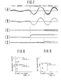
- the band-pass filter 204 serves as low-pass filter for filtering the high-frequency components out of the output signal of the ultra-sonic sensor 202 ( Figure'7(A)) in order to pick up only the low-frequency components as shown in Figure 7(B).
- the low-pass filter 204 is connected to the AC-DC converter 208.
- the AC-DC converter 208 converts the output signal of the low-pass filter indicative of the amplitude of the low-frequency components of the ultra-sonic sensor output signal into a corresponding direct-current signal as shown in Figure 7(D).
- the AC-DC converter 208 is connected for output to the non-inverting input terminal of the comparator 212.
- the band-pass filter 206 is adapted to filter the low-frequency components out of the ultra-sonic sensor output signal so as to pick up only the high-frequency components as shown in Figure 7(C).
- the output signal of the high-pass filter 206 is fed to the AC-DC converter 210.
- the AC-DC converter 210 produces a direct-current signal shown in Figure 7(E) indicative of the amplitude of the high-frequency components of the ultra-sonic sensor output signal.
- the direct current level signal output from the AC-DC converter 210 is applied to the comparator 214 through its non-inverting input terminal.
- the inverting input terminals of the comparators 212 and 214 receive inputs from reference signal generators 216 and 218 respectively.
- the reference signal generator 216 has a voltage divider 220 consisting of resistors R 1 and R 2 .
- the junction 222 through which the reference signal generator 216 is connected to the inverting input terminal of the comparator 212, is connected to the output terminal of the comparator 214 via a diode D 2 and a resistor R 4 .
- the junction 222 is also connected to the controller 100 via an inverter 224, a diode D 1 and a resistor R 3 for purposes discussed later.
- the signal level D of the reference signal produced by the reference signal generator 216 varies depending upon the output of the comparator 214 and the signal level C of control signal So from the controller.
- the reference signal level of the reference signal generator 216 can be obtained from the following equation: where
- the reference signal generator 218 has a voltage divider 226 consisting of a pair of resistors R 5 and R 6 .
- a junction 228 between the resistors R s and R 6 is connected to the inverting input terminal of the comparator 216.
- the junction 228 is connected to the controller 100 via the inverter 224, a diode D 3 and a resistor R 7 -
- the signal level of the reference signal produced by the reference signal generator 218 varies depending upon the signal level of the control signal from the controller 100.
- the signal level of the reference signal of the reference signal generator 218 can be obtained from the following equation: where
- the controller 100 is connected for input from the output terminal of the comparator 212 and outputs a control signal value at either a HIGH level, by which the shock absorber is shifted to HARD mode or at a LOW level shifting the shock absorber to the SOFT mode.
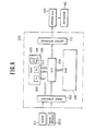
- FIG. 4 shows the controller 100 which generally comprises a microprocessor.
- the microprocessor performs control operations not only depending upon the road surface conditions but also depending upon vehicle speed, other vehicle driving conditions, such as vehicle acceleration, and other preselected suspension control parameters.
- One of these suspension control parameters is the HIGH- or LOW-level output signal from the comparator 214, which switch the damping characteristics of the shock absorber between the HARD and SOFT modes respectively.
- the microprocessor 100 generally comprises an input interface 102, CPU 104, RAM 106, ROM 108 and output interface 110.
- the microprocessor 100 is connected to the road sensor 200 via the input interface 102.
- the microprocessor 100 is also connected for input from a clock generator 112.
- RAM 106 includes a memory block 114 serving as a mode-indicative flag F DH which is set while the shock absorber is operating in HARD mode.
- ROM 108 includes a memory block 116 holding the road surface-dependent suspension control program as an interrupt program triggered by a HIGH-level signal from the comparator 214.
- ROM 108 also has a memory block 118 storing a ultra-sonic sensor control program which triggers the ultra-sonic sensor at a given timing.
- the output interface 110 of the microprocessor 100 is connected for output of control signal S c to each of the driver signal generators.
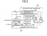
- the ultra-sonic sensor 202 comprises generally an ultra-sonic wave transmitter 230 and a reflected ultra-sonic wave receiver 232.
- the transmitter 230 is associated with the controller 100 to receive therefrom a trigger signal S Tr at a given timing.
- the transmitter 230 includes an ultra-sonic oscillator 234 and an ultra-sonic wave transmitting section 236.
- the ultra-sonic oscillator 234 is responsive to the trigger signal S Tr from the controller 100, which is issued periodically or intermittently, to transmit or discharge ultra-sonic waves through the transmitter section 236 toward the road surface.
- the ultra-sonic waves reflected by the road surface are received by a receiver section 238 of the receiver 232.
- the receiver section 238 produces a receiver signal S RC having value varying in accordance with the amplitude of the received ultra-sonic waves.
- the receiver section 238 is connected to an amplifier 240 to supply the receiver signal S RC to the latter.
- the receiver signal S RC is amplified by the amplifier 240 and transmitted to a rectifier 242.
- the rectifier 242 is connected to the band-pass filters 204 and 206 as set forth above, through a shaping circuit 244.
- the rectifier 242 is also connected to a peak-hold circuit 246 which holds the peak value of the receiver signal.
- the peak-hold circuit 246 produces an analog peak-value-indicative signal Sp e having a value proportional to the held peak value.
- the peak-hold circuit 246 is connected for output to the controller 100 via an analog-to-digital converter 248.
- the analog-to-digital converter 248 outputs a binary signal indicative of the peak-value-indicative signal value to the controller 100.
- the peak-hold circuit 246 is also connected to the controller 100 to receive the trigger signal S T ,.
- the peak-hold circuit 246 is responsive to the trigger signal from the controller to clear the currently held value.
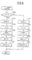
- Figure 6 shows a timing control program executed by the controller 100 for controlling the trigger timing of the ultra-sonic sensor 200.
- a trigger-signal-output-indicative flag F Tr in a memory block 120 of RAM is checked at a step 1002.
- the trigger signal F Tr is set when the trigger signal is output through the output interface 110 to the transmitter 230 and is reset when the trigger signal is not being output.
- the trigger signal-indicative flag F T is set when checked at the step 1002, then the timer value T 1 of a timer 122 in RAM is latched at a step 1004.
- the timer 122 continuously counts clock pulses from the clock generator 112.
- a trigger-signal-ON-time indicative time value t t is added to the latched timer value T, at a step 1006.
- the resultant value (T 1 +t 1 ), which serves as a trigger-signal-OFF time value, is transferred to and stored in a T 2 -register 124 in RAM 106, at a step 1008.
- the flag F Tr is set at a step 1010.
- a HIGH-level output is applied to the output interface as trigger signal STr at a step 1012.
- the potential at the output interface is held HIGH to continue application of the trigger signal S Tr to the transmitter 230.
- the timer 122 continues counting the clock pulses and produces a T 1 -timer signal after period t l which serves as a trigger signal for the timing control program.
- the time data t 2 has a value corresponding to a predetermined interval between successive trigger signals.
- the resultant time value (T 2 +t 2 ) is stored in the T I -timer 122 of RAM 106 at a step 1018.
- the flag F Tr is reset at a step 1020.
- the output level at the output interface drops to LOW to terminate transmission of the trigger signal to the transmitter, at a step 1022.
- the potential at the junction 222 corresponds to the power source voltage as divided by the voltage divider 220, i.e. A o , as shown by the solid line in Figure 8.
- the control signal produced by the controller 100 is LOW, holding the shock absorber in SOFT mode.
- the amplitude of the low-frequency component of the ultra-sonic sensor varies according to the nature of the waviness of the road surface. For instance, when the peak-to-peak spacing of road features is much greater than their peak-to-trough vertical displacment, the vehicle body vibrations may be relatively weak. In this case, as the actual change in the sensor-to-road distance is relatively small, the amplitude of the low-frequency component of the ultra-sonic sensor 202 will remain relatively low. On the other hand, if the spacing of the road features is relatively short in relation of the peak-to-trough height, the vehicle body vibrations may become significant. In this case, the rate of change of the sensor-to-road distance per unit time become greater, resulting in a relatively high-amplitude low-frequency component of the ultra-sonic sensor signal.
- the output of the comparator 212 will go HIGH.
- the controller 100 is responsive to the HIGH-level comparator output to produce a HIGH-level control signal and so operate the shock absorber in HARD mode.
- the input level to the reference signal generator 218 via the inverter 224 becomes logical value "0".
- the diode D 3 thus becomes conductive to allow some of the current available at the junction 228 via the voltage divider of resistors R 5 and R 6 to drain through the resistor R 7 .
- the output level of the reference signal generator 218 is lowered by a value BC, as shown in Figure 9.
- the diode D, in the reference signal generator 216 is also turned on by the LOW teve) input from the inverter 224. As a result, part of the current at the junction 222 is allowed to flow through the resistor R 3 and the diode D,.
- Both the high- and low-frequency components of the ultra-sonic sensor 202 are increased due to the overall roughness of the road surface. Since the low-frequency component of the ultra-sonic sensor output remains relatively strong, the output level of the comparator 212 and of the controller 100 remain HIGH, ordering continued HARD-mode operation of the shock absorber.
- a HIGH-level control signal results in current drain via the diodes D, and D 3 of respective reference signal generators 216 and 218.
- the increase in the amplitude of the high-frequency component of the ultra-sonic sensor 202 means that the input level at the non-inverting input terminal of the comparator 218 increases, as shown in Figure 7(E).
- the output level of the comparator 214 goes HIGH.
- the HIGH-level comparator output is applied to the junction 222 of the reference signal generator 216 via the diode D 2 and the resistor R 4 .
- the reference signal level of the reference signal generator 216 increases by an amount a 2 D, to the level shown in broken line in Figure 8. This increase in the reference signal level of the reference signal generator 216 applied to the comparator 212 prevents the road wheel vibrations from influencing recognition of the road surface waviness.
- FIG 10 shows the detailed structure of a variable-damping-force shock absorber 12 employed in the first embodiment of the suspension control system according to the present invention.
- the shock absorber 12 generally comprises inner and outer hollow cylinders 20 and 22 arranged coaxially, and a piston 24 fitting flush within the hollow interior of the inner cylinder 20.
- the piston 24 defines upper and lower fluid chambers 26 and 28 within the inner cylinder 20.
- the inner and outer cylinders define an annular fluid reservoir chamber 30.
- the piston 24 is connected to the vehicle body (not shown) by means of a piston rod which is generally referred to by the reference number 32.
- the piston rod 32 comprises upper and lower segments 34 and 36.
- the upper segment 34 is formed with an axially extending through opening 38.
- the lower end of the through opening 38 opens into a recess 40 defined on the lower end of the upper segment 34.
- the lower segment 36 has an upper section 42 engageable to the recess 40 to define therein a hollow space 44.
- An actuator is disposed within space 44.
- the actuator 46 is connected to the driver circuit 16 through a lead 48 extending through the through opening 38.
- the actuator 46 is associated with a movable valve body 50 which has a lower end extension 52 inserted into a guide opening 54 defined in the lower segment 36.
- the guide opening 54 extends across a fluid passage 56 defined through the lower segment 36 for fluid communication between the upper and lower fluid chambers 26 and 28.
- the fluid passage 56 serves as a bypass for flow-restrictive fluid passages 58 and 60 formed in the piston 24.
- the upper end of the fluid passage 58 is closed by a resilient flow-restricting valve 62.
- the lower end of the fluid passage 60 is closed by a flow-restricting valve 64.
- the flow-restricting valves 62 and 64 serve as check valves for establishing one-way fluid communication in opposite directions.
- the flow-restriction valves 62 and 64 are biased toward the ends of the fluid passages 58 and 60, they open to allow fluid communication between the upper and lower fluid chambers 26 and 28 only when the fluid pressure difference between the upper and lower chambers 26 and 28 overcomes the effective pressure of the valves.
- the cross-sectional area of the fluid passages 58 and 60 and the set pressures of the fluid-restriction valves 60 and 62 determine the damping force produced in HIGH damping force mode.
- the cross-sectional area of the fluid passage 56 determines the drop in the damping force in the LOW damping force mode in comparison with that in the HIGH damping force mode.
- the movable valve body 50 is normally biased upwards by means of a coil spring 51.
- the actuator 46 when the actuator 46 is not energized, the lower end section 52 of the valve body 50 is separated from the fluid passage 56 to allow fluid communication between the upper and lower chamber.
- the valve body 50 moves downwards against the resilient force of the coil spring 51 to block the fluid passage 56 with the lower end extension 52.
- fluid communication between the upper and lower fluid chambers 26 and 28 via the fluid passage 56 is blocked.
- the damping force produced by the shock absorber 14 remains LOW.
- the fluid passage 56 when the fluid passage 56 is shut, fluid flow rate is reduced, thus increasing the damping force produced. Therefore, when the valve body 50 is shifted to the lowered position, the shock absorber works in HIGH damping force mode to produce a higher damping force against vertical shocks.
- a bottom valve 66 is installed between the lower fluid chamber 28 and the fluid reservoir chamber 30.
- the bottom valve 66 is secured to the lower end of the inner cylinder and includes fluid passages 68 and 70.
- the upper end of the fluid passage 68 is closed by a flow-restriction valve 72.
- the lower end of the fluid passage 70 is closed by a flow-restriction valve 74.
- the movable valve body 50 In the normal state wherein the control signal of the controller 100 remains LOW, the movable valve body 50 is held in its upper position by the effect of the spring force 51 so that the lower end extension 52 does not project into the fluid passage 56. Therefore, the fluid communication is established through both the fluid passage 56 and the applicable one of the flow-restricting fluid passages 58 and 60. As a result, the total flow restriction is relatively weak to allow the shock absorber to operate in SOFT mode.
- the driver signal generator 102 corresponding to each shock absorber 12 becomes active to energize the actuator 46.
- the actuator 46 drives the movable valve body 50 downward. This downward movement shifts the lower end of the extension 52 of the valve body 50 into the fluid passage 56 so as to block fluid communication between the upper and lower fluid chambers 26 and 28 via the fluid passage 56. Therefore, the fluid can flow between the upper and lower chambers 26 and 28 only through one of the fluid passages 58 and 60.
- the fluid flow restriction is, thus, increased, resulting in a greater damping force than is produced in the SOFT mode. In other words, the shock absorber 12 operates in HARD mode.
- FIGs 11 to 14 show a modified form of the variable-damping-characteristic shock absorber of Figure 10.
- the shock absorber 12 can be operated in any of three modes, namely HARD mode, SOFT mode and MEDIUM mode, in the last of which damping characteristics intermediate to those of HARD mode and SOFT mode are achieved.
- the hydraulic shock absorber 12 has coaxial inner and outer cylinders 302 and 304. Top and bottom ends of the cylinders 302 and 304 are plugged with fittings 306 and 305.
- the fitting 306 includes a seal 307 which establishes a liquid-tight seal.
- a piston rod 308 extends through an opening 312 formed in the fitting 306 and is rigidly connected to a vehicle body (not shown) at its top end. The piston rod 308 is, in turn, connected to a piston 314 reciprocally housed within the inner cylinder 302 and defining upper and lower fluid chambers 316 and 318 therein.
- the piston 314 has fluid passages 320 and 322 connecting the upper and lower fluid chambers 316 and 318.
- the piston 214 also has annular grooves 324 and 326 along its upper and-lower surfaces concentric about its axis.
- the upper end of the fluid passage 320 opens into the groove 324.
- the lower end of the fluid passage 322 opens into the groove 326.
- Upper and lower check valves 328 and 330 are provided opposite the grooves 324 and 326 respectively to close the grooves when in their closed positions.
- the lower end of the fluid passage 320 opens onto the lower surface of the piston at a point outside of the check valve 330.
- the upper end of the fluid passage 322 opens onto the upper surface of the piston at a point outside of the check valve 328.
- the fluid passage 322 is active during the piston expansion stroke, i.e. during rebound of the shock absorber. At this time, the check valve 328 prevents fluid flow through the fluid passage 320.
- the fluid passage 320 is active, allowing fluid flow from the lower fluid chamber 318 to the upper fluid chamber 316 and the fluid passage 322 is blocked by the check valve 330.
- the piston rod 308 has a hollow cylindrical shape so that a damping force adjusting mechanism, which will be referred to generally by the reference numeral "400" hereafter, can be housed therein.
- the damping force adjusting mechanism 400 includes a valve mechanism 402 for adjusting the cross-sectional area through which the working fluid can flow between the upper and lower chambers.
- the valve mechanism 402 allows three steps of variation of the damping force, i.e., HARD mode, MEDIUM mode and SOFT mode, the narrowest cross-sectional area representing the HARD mode, the widest the SOFT mode and intermediate the MEDIUM mode.
- the piston rod 308 defines an axially extending through opening 404 with the lower end opening into the lower fluid chamber 318.
- a fitting 408 seals the lower end of the opening 404 of the piston rod and has axially extending through opening 410, the axis of which is parallel to the axis of the through opening 404 of the piston rod.
- the through openings 404 and 410 constitute a fluid path 412 ' extending through the piston rod.
- the piston rod 308 also has one or more radially extending orifices or openings 414 opening into the upper fluid chamber 316.
- the upper and lower fluid chambers 316 and 318 are in communication through the fluid path 412 and the radial orifices 414.
- a stationary valve member 416 with a flaring upper end 418 is inserted into the through opening 404 of the piston rod.
- the outer periphery of the flaring end 418 of the stationary valve member 416 is in sealing contact with the internal periphery of the through opening.
- the stationary valve member 416 has a portion 420 with a smaller diameter than that of the upper end 418 and so as to define an annular chamber 422 in conjunction with the inner periphery of the through opening 404 of the piston rod.
- the stationary valve member 416 has two sets of radially extending orifices 424 and 426 and an internal space 428. The radially extending orifices 424 and 426 establish communication between the internal space 428 and the annular chamber 422.
- a movable or rotary valve member 430 is disposed within the internal space 428 of the stationary valve member 416.
- the outer periphery of the rotary valve member 430 slidingly and sealingly contacts the inner surface of the stationary valve member 416 to establish a liquid-tight seal therebetween.
- Radially extending orifices 432 and 434 are defined in the rotary valve member 430 at positions opposite the orifices 424 and 426 of the stationary valve member 416.
- the orifices 424 and 426 respectively includes first, second and third orifices 424a, 424b, 424c, and 426a, 426b, and 426c.
- the first orifices 424a and 426a have the narrowest cross-sections and the orifices 432 and 434 are adapted to be in alignment with the first orifices to establish fluid communication between the upper and lower fluid chambers 316 and 318 in the case of the HARD mode.
- the third orifices 424c and 426c have the widest cross-sections and the orifices 432 and 434 are adapted to be in alignment with the third orifices in the case of the SOFT mode.
- the cross-sections of the second orifices 424b and 426c are intermediate those of the first and third orifices and the orifices 432 and 434 are adapted to align therewith in the case of the MEDIUM mode.
- a check valve 436 is provided within an internal space of the rotary valve member 430.
- the check valve 436 is normally biased towards a valve seat 438 by means of a bias spring 440 for allowing one-way fluid flow from the lower fluid chamber to the upper fluid chamber. This cause the bound damping force to be somewhat weaker than the rebound damping force.
- the rotary valve member 430 is associated with an electrically operable actuator such as an electrical step motor 442 through a differential gear unit 444 and an output shaft 446 as shown in Figure 14.
- a potentiometer 448 is associated with the output shaft 446.
- the potentiometer 448 includes a movable contact 450 with contactors 450a, 450b and 450c.
- the contactors 450a, 450b and 450c are adapted to slidingly contact stationary contact elements 452a, 452b and 452c of a stationary contact 452.
- the potentiometer 448 According to the electrical connections between the movable contact and the stationary contact, the potentiometer 448 produces a mode signal representative of the rotary valve position and thus indicative of the selected mode of the damping force adjusting mechanism.
- the step motor 442 is electrically connected to a controller 100 to receive the control signal as a mode selector signal which drive the motor 442 through an angle corresponding to the rotary valve movement to the corresponding valve position.
- the potentiometer will return the mode signal as a feedback signal to indicate the instantaneous valve position.
- controller 100 may be operated either in automatic mode or in manual mode.
- the shock absorber has a fluid reservoir chamber 332 between its inner and outer cylinders 302 and 304, which fluid reservoir chamber 332 is in communication with the lower fluid chamber 318 via the bottom fitting 305 described previously.
- the bottom fitting 305 may serve to produce damping force in cooperation with the piston and the damping force adjusting mechanism during bounding and rebounding motion of the vehicle.
- a relatively low pressure pneumatic chamber 336 is also defined between the inner and outer cylinders 302 and 304.
- FIGS 13(A) and 13(B) show the case of the HARD mode.
- the orifice 432 of the rotary valve 430 is in alignment with the orifice 424a and the orifice 434 is in alignment with the orifice 426a.
- vehicle rebounding motion i.e., in the piston compression stroke
- the fluid flows from the upper fluid chamber 316 to the lower fluid chamber 318 through the orifice 426a.
- vehicle bounding motion the fluid flows from the lower fluid chamber 318 to the upper fluid chamber 316 through orifices 424a and 426a. Since the first orifices 424a and 426a are the narrowest, the damping force produced in this mode is the highest among the three selectable modes.
- the orifices 432 and 434 of the rotary valve member 430 are respectively in alignment with the second orifices 424b and 426b.
- the orifices 432 and 434 align with the third orifices 424c and 426c, respectively to cause fluid flow. Since the third orifices 424c and 426c are the widest of the three sets, as described above, the damping force created in this SOFT mode is the lowest.
- the electric step motor 442 is connected to the controller 100 through the driver circuit 16.
- the controller 100 selects any appropriate damping force state in accordance with detected road surface conditions but in this case produces a three-way control signal for actuating the shock absorber to one of the SOFT, MEDIUM, and HARD modes.
- the driver circuit 16 is responsive to the control signal to drive the step motor 442 to operate the rotary valve member 430 to the corresponding valve position.
- FIGS 15 to 17 show a second embodiment of the suspension control system according to the present invention.
- This second embodiment also employs the variable damping force shock absorber identical to that disclosed with respect to the first embodiment of the invention.
- this embodiment employs a vibration sensor for detecting the relative displacement between the vehicle body and the road wheel axle, instead of the ultra-sonic sensor employed in the first embodiment.
- the vibration sensor 500 is associated with a shock absorber in order to monitor axial displacement of the piston rod thereof.
- the vibration sensor 500 produces an AC vibration sensor signal with a value representative of the relative displacement between the vehicle body and the road wheel axle.
- the vibration sensor signal is fed to a high-frequency filter circuit 502 and a low-frequency filter circuit 504.
- the high-frequency filter circuit 502 is adapted to remove the high-frequency components from the vibration sensor signal and pass only the low-frequency components thereof.
- the high-frequency filter circuit 502 outputs a direct-current signal representative of the magnitude of vibration of the vehicle body, which signal will be referred to hereafter as "low-frequency component indicative signal”.
- the low-frequency filter circuit 504 is adapted to remove the low-frequency components from the vibration sensor signal and pass only the high-frequency components thereof.
- the low-frequency filter circuit 504 produces a direct-current signal representative of the magnitude of high-frequency vibrations of the road wheel axle, which signal will be referred to hereafter as "high-frequency component indicative signal”.
- the low-frequency component indicative signal from the high-frequency filter circuit 502 is input to a comparator 506 through its non-inverting input terminal.
- the high-frequency component indicative signal of the high-frequency component filter circuit 504 is input to a comparator 508 through its non-inverting input terminal.
- Each of the comparators 506 and 508 has inverting input terminals connected to a corresponding reference signal generator 510 or 512.
- the comparator 506 has the output terminal connected to a controller 514 which is substantially the same as set forth with respect to Figure 4 and produces a control signal to operate the shock absorber between HARD and SOFT modes.
- the output terminal of the comparator 508 is connected to the reference signal generator 510.
- the reference signal generator 510 has a voltage divider 516 including resistors R, o and R" which generates a predetermined voltage at the junction 518 between the resistors. Through the junction 518, the reference signal generator 510 is connected to the inverting input terminal of the comparator 506. The junction 518 is also connected to the controller 514 via a diode D 10 and a resistor R 12 to receive therefrom the control signal. Also, the junction 518 is connected to the output terminal of the comparator 506 via a diode 0 " and a resistor R, 3 .
- the reference signal generator 512 has a voltage divider 520 including resistors R 14 and R, 5 with a junction 522 therebetween. The junction 522 is connected to the controller 514 through a diode D 12 and a resistor R 16 .
- the inverter is omitted and the polarity of the diodes between the junctions and the controller is reversed. This is due to the fact that, since the sensitivity of the-vibration sensor is boosted by the greater damping force produced in the HARD mode of shock absorber operation, compensating by increasing the reference value is necessary achieved for uniform detection of the HARD suspension criterion.
- Figures 20 and 21 illustrate the behavior of the reference signals at the junctions 518 and 522 respectively in response to extremes of road surface condition.
- the comparators 506, 508 and the controller 514 all output low-level signal due to the relatively low-amplitude sensor inputs.
- the generator 510 since neither reference signal generator 510, 512 receives a boost from the controller, and the generator 510 similarly is not boosted by the comparator 508 via diode D 11 , the divider voltages E o , F o are applied without modification to the inverting input terminals of the corresponding comparators 506, 508.
- the comparators 506, 508 output HIGH-level signals.
- the first reference generator 510 may receive one boost G from the comparator 508 out certainly receives a boost H from the controller 514.
- the second reference generator 512 receives a single boost I from the controller 514.
- the boost G is applied to the reference voltage at junction 518 when high-frequency wheel vibrations are detected and the comparator outputs a HIGH-level signal.
- Figures 16 shows a suspensions strut assembly employed in the second embodiment of suspension control system according to the present invention, of Figure 15.
- the strut assembly includes a shock absorber 524 having variable damping characteristics and operable in either HARD or SOFT mode.
- a piston rod 526 extends from the shock absorber cylinder 528 and is connected to a strut housing 530 of the vehicle body through a mounting bracket 532.
- a rubber insulator 534 is interpositioned between the mounting bracket 532 and the strut housing 530 for absorbing vibrations transmitted between the vehicle body and the shock absorber.
- a suspension coil spring 536 is wound around the piston rod 526 of the shock absorber.
- the lower end of the suspension coil spring 536 seats on a lower spring seat 538 fixed to the outer periphery of the outer shock absorber cylinder.
- the upper end of the suspension coil spring 536 seats on an upper spring seat 540 which is connected to the mounting bracket 532 via a bearing assembly 542.
- the bearing assembly 542 allows the strut assembly to pivot freely about the piston rod 526.
- the upper spring seat 540 is rigidly secured to a dust insulator cover 544, to which the upper end of elastically deformable rubber dust insulator 546 is secured.
- the lower end of the dust insulator 546 is secured to the outer periphery of the outer cylinder of the shock absorber.
- a closure 548 with a connecting ring 550 is fitted to the bottom of the shock absorber cylinder.
- the shock absorber cylinder is connected to a suspension arm (not shown) via the connecting ring.
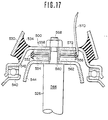
- the vibration sensor 500 is inserted between the mounting bracket 532 and the strut housing 530. As shown in Figure 17, the vibration sensor 500 has a pair of piezoelectric elements 552 and 554 sandwiching a terminal plate 556.
- the piezoelectric element 552 is fixed to a disc plate 558 with an axially extending cylindrical section 560.
- the disc plate 558 is fixed to the mounting bracket 532 for motion therewith.
- the piezoelectric element 554 is secured to a disc plate 562 which is, conversely, fixed to the cover plate 544 which is fixedly mounted on a step 564 formed between the shaft 566 and the threaded end 568 of the piston rod.
- the cylindrical section 560 surrounds the threaded section 568 of the piston rod.
- a lead wire 570 extends from the terminal plate 556 through a rubber seal 572.
- the lead wire 570 is connected to the high-frequency filter circuit 502 and the low-frequency filter circuit 504.
- the output of the vibration sensor 500 i.e., the vibration sensor signal, is thus fed to the filter circuits 502 and 504 via the terminal plate 556 and the lead wire 570.
- the vibration sensor 500 constructed as above is not responsive to the static load applied to the vehicle, which generally causes a lowering of the vehicle level, such as passengers and/or luggage.
- the vibration sensor 500 is thus responsive only to dynamic loads due to vertical displacements and forces applied to the road wheel and vehicle body.
- the vibration sensor signal is thus indicative solely of the dynamic load applied to the vibration sensor 500.
- the high-frequency filter circuit 502 may alternatively comprise a low-pass filter 502-1, a high-pass filter component 502-2, a full-wave rectifier 502-3 and a smoothing circuit 502-4.
- the low-pass filter is adapted to remove high-frequency components from the vibration sensor signal and pass only the low-frequency components.
- the low-pass filter 502-1 removes signal component at frequencies above 3 to 5 Hz so as to resolve signal components in the range of 1 to 2 Hz.
- the high-pass filter 502-2 is adapted to remove very-low-frequency components from the output of the low-pass filter for the sake of noise suppression. In practice, the high-pass filter 502-2 is intended to remove frequency components below 0.2 to 0.3 Hz.
- the low-frequency filter circuit 504 comprises a high-pass filter 504-1, a full-wave rectifier 504-2 and a smoothing circuit 504-3.
- the high-pass filter is, in practice, designed to filter out signal components at frequencies below 3 to 5 Hz so as to pick signal components in the frequency range of 12 to 13 Hz.
- the vibration sensor signal (A) is filtered by the low-pass filter 502-1 and the high-pass filter 504-1, as illustrated in (F) and (B).
- the low-frequency component of Figure 19(F) passes through the high-pass filter 502-2, leaving only the signal components in the frequency range of 1 to 2 Hz.
- the output (G) of the high-pass filter is rectified by the full-wave rectifier 502-3 into the waveform of Figure 19(H).
- the output of the full-wave rectifier 502-3 is smoothed by the smoothing circuit 502-4 into the waveform of Figure 19(1).
- the output of the high-pass filter 504-1 of Figure 19(8) is rectified by the full-wave rectifier 504-2 into the waveform of Figure 19(C).
- the rectifier output is smoothed by the smoothing circuit 504-3 into the waveform of Figure 19(D).
- the smoothed signals are respectively fed to the corresponding comparators 506 and 508.
- the recognized road surface condition can be used in substantially the same manner as that disclosed with respect to the first embodiment.
- FIG 22 shows a modification to the road sensor in the second embodiment of suspension control system according to the invention.
- comparators 507 and 509 are added.
- the comparator 507 is connected in parallel with the comparator 506 and its non-inverting input terminal is connected for input from the smoothing circuit 502-4.
- the inverting input terminal of the comparator 507 is connected to a reference signal generator 511.
- the comparator 509 is connected in parallel with the comparator 508 and connected to the smoothing circuit 504-3 at its non-inverting input terminal.
- the inverting input terminal of the comparator 509 is connected to a reference-signal generator 513.
- the reference signal generator 511 is adapted to produce a reference signal having a value smaller than the reference signal produced by the reference signal generator 510.
- the reference signal generator 513 is adapted to produce a reference signal having a value smaller than that of the reference signal of the reference signal generator 512.
- the vibration magnitude of the road wheel and vehicle body can be resolved according to the following table:
- road surface conditions may be more precisely detected than in the previously described systems according to the following table:
- FIG 23 shows another modification of the second embodiment of the suspension control system of Figure 15.
- analog-to-digital converters (A/D converters) 580 and 582 are connected for input from the smoothing circuits 502-4 and 504-3.
- the A/D converters convert the analog smoothing circuit outputs into binary values representative of the amplitude of the smoothing circuit outputs for direct application to the digital controller 100.
- the second embodiment has been illustrated as employing a vibration sensor to detect relative displacement between the vehicle body and the road wheel, this may be replaced by a well-known vehicle body height sensor, accelerometer, strain gauge or the like.
- FIG. 24 shows a further modification to the second embodiment of the suspension control system according to the present invention.
- a comparator 590 is connected to the full-wave rectifier 502-3 to receive the rectified signal through its non-inverting input terminal.
- the inverting input terminal of the comparator 590 is connected to a reference signal generator 591.
- the reference signal generator 591 produces a reference signal having a value representative of the hard-suspension criterion, e.g. vibrations due to the vehicle passing over a bump or depression on the road surface.
- the output terminal of the comparator 590 is connected to a trigger circuit 592 which is adapted to output a LOW-level pulse for a given period of time, e.g.
- the trigger circuit 592 is connected for output to a NOR gate 594 which also receives an input from the low-frequency filter circuit 504.
- the output terminal of the NOR gate is connected to a retriggerable monostable multivibrator 596.
- the NOR gate 594 outputs a HIGH-level signal when the trigger signal from the trigger circuit 592 is HIGH and the input from the filter circuit 504 remains LOW.
- the HIGH-level output of the NOR gate triggers the monostable multivibrator 596 to make the latter output a LOW-level signal for a given period of time.
- the controller 100 receives the output of the monostable multivibrator 596 and issue a HIGH-level control signal to switch the shock absorber into HARD mode for the period of time for which the monostable multivibrator output remains LOW.
- the suspension control system temporarily hardens the shock absorber as the vehicle passes over a bump or a depression on the road surface and exhibits good response characteristics.
- FIG. 25 shows the third embodiment of the suspension control system in accordance with the present invention.
- a known vehicle height control system is used for hardness control of the suspension.
- Such vehicle height control 4,349,077 to Sekiguchi et al, U.S. Patent US ⁇ A ⁇ 4,327,936 to Sekiguchi systems have been disclosed in U.S. Patent and European Patent First Publication EP-A-0 114 700, published on August 1, 1984, for example.
- Detailed constructions of the suspension system with vehicle height control as disclosed in the above-referenced publications are hereby incorporated by reference for the sake of disclosure.
- an expandable and contractable pneumatic chamber 600 is formed above the shock absorber 602.
- the pneumatic chamber 600 is connected to a pressurized pneumatic fluid source 604.
- the fluid source 604 comprises a compressor 606 for pressurizing a fluid such as air, a reservoir tank 608 connected to the compressor 606 through an induction valve 610, and a pressure control valve 612.
- the pressure control valve 612 and the induction valve 610 are connected to the driver signal generator 102 to be controlled thereby.
- the driver circuit 102 is connected to the controller 100.
- pressure control valve 612 closes to block pneumatic fluid communication between the pneumatic chamber 600 and the fluid reservoir 608.
- the effective volume of the pneumatic chamber 600 is precisely that of the pneumatic chamber itself. Since the damping characteristics due to the pneumatic pressure in the pneumatic chamber is related to the effective volume of the pneumatic chamber and a smaller effective volume is achieved by blocking fluid communication between the pneumatic chamber and the fluid reservoir, the pneumatic chamber becomes relatively rigid in this case, providing a larger damping force in response to vehicle body-chassis displacement.
- the pressure control valve 612 opens to allow fluid communication between the pneumatic chamber and the fluid reservoir.
- the effective volume becomes equal to the sum of the volumes of the pneumatic chamber and the fluid reservoir.
- the vehicular suspension system can provide both riding comfort and good drivability by controlling hardness of the suspension depending upon the road surface conditions.
Landscapes
- Engineering & Computer Science (AREA)
- Mechanical Engineering (AREA)
- Radar, Positioning & Navigation (AREA)
- Remote Sensing (AREA)
- General Engineering & Computer Science (AREA)
- Physics & Mathematics (AREA)
- Acoustics & Sound (AREA)
- Computer Networks & Wireless Communication (AREA)
- General Physics & Mathematics (AREA)
- Vehicle Body Suspensions (AREA)
Claims (22)
Applications Claiming Priority (4)
| Application Number | Priority Date | Filing Date | Title |
|---|---|---|---|
| JP8196/84 | 1984-01-20 | ||
| JP8199/84 | 1984-01-20 | ||
| JP819684A JPS60151108A (ja) | 1984-01-20 | 1984-01-20 | 路面状態検出装置 |
| JP819984A JPS60151111A (ja) | 1984-01-20 | 1984-01-20 | 車両の揺動制御装置 |
Publications (3)
| Publication Number | Publication Date |
|---|---|
| EP0151421A2 EP0151421A2 (fr) | 1985-08-14 |
| EP0151421A3 EP0151421A3 (en) | 1985-12-11 |
| EP0151421B1 true EP0151421B1 (fr) | 1988-09-07 |
Family
ID=26342665
Family Applications (1)
| Application Number | Title | Priority Date | Filing Date |
|---|---|---|---|
| EP85100527A Expired EP0151421B1 (fr) | 1984-01-20 | 1985-01-18 | Système de commande pour suspension de véhicule à caractéristiques d'amortissement sensibles aux conditions routières |
Country Status (3)
| Country | Link |
|---|---|
| US (4) | US4770438A (fr) |
| EP (1) | EP0151421B1 (fr) |
| DE (1) | DE3564786D1 (fr) |
Cited By (1)
| Publication number | Priority date | Publication date | Assignee | Title |
|---|---|---|---|---|
| DE3937841A1 (de) * | 1988-11-14 | 1990-05-17 | Atsugi Unisia Corp | System zur erfassung von strassenunebenheit fuer eine aufhaengungssteuerung und kraftfahrzeug-aufhaengungssteuerungsystem, welches die erfasste strassenunebenheit als steuerparameter verwendet |
Families Citing this family (175)
| Publication number | Priority date | Publication date | Assignee | Title |
|---|---|---|---|---|
| US4770438A (en) * | 1984-01-20 | 1988-09-13 | Nissan Motor Co., Ltd. | Automotive suspension control system with road-condition-dependent damping characteristics |
| IT1196700B (it) * | 1984-05-11 | 1988-11-25 | Fiat Auto Spa | Dispositivo per il controllo degli ammortizzatori delle sospensioni particolarmente per autovetture |
| JPS6118513A (ja) * | 1984-07-04 | 1986-01-27 | Nissan Motor Co Ltd | 車両用サスペンシヨン制御装置 |
| US4589676A (en) * | 1984-12-13 | 1986-05-20 | General Motors Corporation | Adaptive ride control for motor vehicle |
| DE3518503C1 (de) * | 1985-05-23 | 1986-10-23 | Daimler-Benz Ag, 7000 Stuttgart | Vorrichtung zur rechnergestuetzten,fahrbahnabhaengigen Steuerung von Daempfern einer Fahrzeugfederung |
| EP0205645A1 (fr) * | 1985-06-26 | 1986-12-30 | Hitachi, Ltd. | Système de commande de suspension |
| DE3534211A1 (de) * | 1985-09-25 | 1987-03-26 | Pfister Gmbh | Kraftfahrzeug und verfahren zu dessen betrieb |
| US4728120A (en) * | 1985-10-03 | 1988-03-01 | Toyota Jidosha Kabushiki Kaisha | Suspension controller |
| FR2588658B1 (fr) * | 1985-10-11 | 1990-03-09 | Jaeger | Procede et dispositif de controle d'une suspension de vehicule par controle de l'adherence |
| JPS62194921A (ja) * | 1986-02-21 | 1987-08-27 | Honda Motor Co Ltd | 緩衝器の減衰力制御方法 |
| GB8610842D0 (en) * | 1986-05-02 | 1986-06-11 | Bl Tech Ltd | Suspension system |
| DE3624493A1 (de) * | 1986-07-19 | 1988-01-21 | Bayerische Motoren Werke Ag | Vorrichtung zur beeinflussung der daempfkraft und/oder federkraft an aufhaengungsteilen eines kraftfahrzeugs |
| DE3761475D1 (de) * | 1986-08-05 | 1990-03-01 | Mazda Motor | Radaufhaengung fuer ein fahrzeug. |
| DE3632919A1 (de) * | 1986-09-27 | 1988-03-31 | Bayerische Motoren Werke Ag | Verfahren zur daempfkraftverstellung von kraftfahrzeugen |
| DE3632920A1 (de) * | 1986-09-27 | 1988-03-31 | Bayerische Motoren Werke Ag | Verfahren zur daempfkraftverstellung von kraftfahrzeugen |
| JPH0799488B2 (ja) * | 1986-10-31 | 1995-10-25 | 株式会社豊田中央研究所 | 振動制御装置 |
| DE3738284A1 (de) * | 1986-12-09 | 1988-06-30 | Bosch Gmbh Robert | Vorrichtung zur aktiven fahrwerkregelung bei kraftfahrzeugen |
| JPH0789059B2 (ja) * | 1987-01-14 | 1995-09-27 | 株式会社日立製作所 | 視覚センサシステム |
| DE3867573D1 (de) * | 1987-09-03 | 1992-02-20 | Toyoda Chuo Kenkyusho Kk | Elektronisch geregeltes fluidumaufhaengungssystem mit vorausberechneter und rueckgekoppelter regelung der fahrzeuglage. |
| EP0306003B1 (fr) * | 1987-09-04 | 1992-01-15 | Toyota Jidosha Kabushiki Kaisha | Système de suspension à fluide pour le réglage du roulis et du tangage de la caisse d'un véhicule |
| JP2509257B2 (ja) * | 1987-11-05 | 1996-06-19 | 日産自動車株式会社 | 能動型サスペンション装置 |
| EP0323020A3 (fr) * | 1987-12-28 | 1991-01-09 | Ford Motor Company Limited | Capteur de hauteur de suspension, actionné par force, pour véhicule automobile |
| ES2011326A6 (es) * | 1988-03-28 | 1990-01-01 | Castillo Castillo Jose Luis | Sistema de amortiguacion de modos de oscilacion de vehiculos con suspension que aprovecha el movimiento relativo entre la parte suspendida y las no suspendidas pra producir fuerzas exclusivamente en el sentido opuesto al movimiento de los modos de oscilacion excitados. |
| DE3810638C1 (fr) * | 1988-03-29 | 1989-08-10 | Boge Ag, 5208 Eitorf, De | |
| DE3821569A1 (de) * | 1988-06-25 | 1989-12-28 | Man Nutzfahrzeuge Ag | Vorrichtung zur ermittlung des einfederniveaus an einem ueber luftfederbaelge abgefederten und stossdaempfer gedaempften fahrzeug |
| US4984820A (en) * | 1988-07-22 | 1991-01-15 | Toyota Jidosha Kabushiki Kaisha | Damping force control system for shock absorber variable with frequency of vehicle height difference exceeding limit value |
| JPH0238174A (ja) * | 1988-07-29 | 1990-02-07 | Aisin Seiki Co Ltd | 路面状態検出装置および車上制御装置 |
| JPH02142942A (ja) * | 1988-11-25 | 1990-06-01 | Atsugi Unisia Corp | 液圧緩衝器 |
| US4936425A (en) * | 1989-02-10 | 1990-06-26 | Lord Corporation | Method of operating a vibration attenuating system having semiactive damper means |
| US4921272A (en) * | 1989-02-10 | 1990-05-01 | Lord Corporation | Semi-active damper valve means with electromagnetically movable discs in the piston |
| GB8910277D0 (en) * | 1989-05-04 | 1989-06-21 | Lotus Group Plc | Land vehicle suspension control system |
| GB8910392D0 (en) * | 1989-05-05 | 1989-06-21 | Lotus Group Plc | A vehicle suspension control system |
| JP2616141B2 (ja) * | 1989-05-29 | 1997-06-04 | 三菱電機株式会社 | サスペンションまたはスタビライザの制御装置 |
| DE4017421C2 (de) * | 1989-05-31 | 1994-09-15 | Mitsubishi Electric Corp | Verfahren und Vorrichtung zur Dämpfungseinstellung an einem Fahrzeug |
| DE3918735A1 (de) * | 1989-06-08 | 1990-12-13 | Bosch Gmbh Robert | Verfahren und vorrichtung zur daempfung von bewegungsablaeufen |
| DE68915442T2 (de) * | 1989-08-03 | 1995-01-05 | Nippon Denso Co | Kontrollsystem für die Dämpfkraft von Stossdämpfern. |
| DE69031794T2 (de) * | 1989-09-11 | 1998-04-23 | Denso Corp | Aufhängungssteuersystem |
| EP0417702B1 (fr) * | 1989-09-11 | 1997-01-08 | Toyota Jidosha Kabushiki Kaisha | Système de contrÔle de suspension |
| US5062658A (en) * | 1989-11-02 | 1991-11-05 | General Motors Corporation | Vehicle suspension control with real time gain switching |
| GB2239506B (en) * | 1989-12-08 | 1993-08-25 | Toyota Motor Co Ltd | Suspension control system |
| JPH03189338A (ja) * | 1989-12-19 | 1991-08-19 | Japan Electron Control Syst Co Ltd | トラクションコントロール装置 |
| JP3041870B2 (ja) * | 1990-02-16 | 2000-05-15 | トヨタ自動車株式会社 | ショックアブソーバ制御装置 |
| JPH03258650A (ja) * | 1990-03-09 | 1991-11-18 | Toyota Motor Corp | 路面摩擦係数検出装置 |
| JP2587627Y2 (ja) * | 1990-05-28 | 1998-12-24 | 株式会社ユニシアジェックス | 減衰力制御装置 |
| US5097419A (en) * | 1990-06-08 | 1992-03-17 | Monroe Auto Equipment Company | Method and apparatus for dynamic leveling |
| US5091679A (en) * | 1990-06-20 | 1992-02-25 | General Motors Corporation | Active vehicle suspension with brushless dynamoelectric actuator |
| US5321217A (en) * | 1990-07-18 | 1994-06-14 | Otis Elevator Company | Apparatus and method for controlling an elevator horizontal suspension |
| US5322144A (en) * | 1990-07-18 | 1994-06-21 | Otis Elevator Company | Active control of elevator platform |
| US5400872A (en) * | 1990-07-18 | 1995-03-28 | Otis Elevator Company | Counteracting horizontal accelerations on an elevator car |
| US5294757A (en) * | 1990-07-18 | 1994-03-15 | Otis Elevator Company | Active vibration control system for an elevator, which reduces horizontal and rotational forces acting on the car |
| US5308938A (en) * | 1990-07-18 | 1994-05-03 | Otis Elevator Company | Elevator active suspension system |
| US5265704A (en) * | 1990-08-07 | 1993-11-30 | Robert Bosch Gmbh | Apparatus for damping courses of motion |
| DE4024966A1 (de) * | 1990-08-07 | 1992-02-13 | Bosch Gmbh Robert | Vorrichtung zur daempfung von bewegungsablaeufen |
| US5110153A (en) * | 1990-09-06 | 1992-05-05 | Teledyne Industries, Inc. | Vehicle for transporting loads |
| DE4029034C2 (de) * | 1990-09-13 | 1999-02-25 | Wabco Gmbh | Einrichtung zur Beeinflussung des Federungsverhaltens einer gefederten Masse |
| US5322319A (en) * | 1990-09-17 | 1994-06-21 | Mitsubishi Jidosha Kogyo Kabushiki Kaisha | Active suspension apparatus for a vehicle |
| US5550739A (en) * | 1990-10-26 | 1996-08-27 | Alfred Teves Gmbh | Semi-active suspension control system |
| US5218546A (en) * | 1990-12-17 | 1993-06-08 | Hughes Aircraft Company | Frequency shaping method for minimizing impact harshness of suspension system |
| US5430646A (en) * | 1991-02-22 | 1995-07-04 | Atsugi Unisia Corporation | System and method for controlling damping force coefficient of shock absorber applicable to automotive supension |
| JP2756207B2 (ja) * | 1991-03-13 | 1998-05-25 | オーチス エレベータ カンパニー | 垂直昇降路レール上のエレベータかごの水平偏差を測定する方法及び装置 |
| JP2756208B2 (ja) * | 1991-03-13 | 1998-05-25 | オーチス エレベータ カンパニー | 垂直走行中のエレベータかごの水平偏差修正装置 |
| GB2255056B (en) * | 1991-04-23 | 1994-12-14 | Lotus Car | A vehicle suspension system |
| US5276621A (en) * | 1991-05-20 | 1994-01-04 | General Motors Corporation | Quarter car variable force suspension system control |
| US5475596A (en) * | 1991-05-20 | 1995-12-12 | General Motors Corporation | Full car semi-active suspension control based on quarter car control |
| US5434782A (en) * | 1991-05-20 | 1995-07-18 | General Motors Corporation | Suspension system state observer |
| US5579230A (en) * | 1991-06-10 | 1996-11-26 | General Motors Corporation | Vehicle speed estimation for antilock braking using a chassis accelerometer |
| CA2072240C (fr) * | 1991-07-16 | 1998-05-05 | Clement A. Skalski | Elements horizontaux de suspension et commandes d'ascenseur |
| JP3080257B2 (ja) * | 1991-08-06 | 2000-08-21 | 株式会社ユニシアジェックス | 車両懸架装置 |
| DE4133238C2 (de) * | 1991-10-05 | 2001-09-27 | Bosch Gmbh Robert | System zur Erlangung eines die Fahrbahnoberfläche repräsentierenden Signals |
| US5396973A (en) * | 1991-11-15 | 1995-03-14 | Lord Corporation | Variable shock absorber with integrated controller, actuator and sensors |
| DE4140270A1 (de) * | 1991-12-06 | 1993-06-09 | Robert Bosch Gmbh, 7000 Stuttgart, De | Verfahren und vorrichtung zur fahrwerkregelung |
| US5322320A (en) * | 1992-01-14 | 1994-06-21 | Nippondenso Co., Ltd. | Shock absorber damping force control system for vehicle |
| KR970011089B1 (ko) * | 1992-02-14 | 1997-07-07 | 미쯔비시 지도샤 고교 가부시끼가이샤 | 노면상태의 식별방법 및 써스펜션의 제어 장치 |
| US5497325A (en) * | 1992-08-31 | 1996-03-05 | Fuji Jukogyo Kabushiki Kaisha | Suspension control system for a vehicle |
| JP3131049B2 (ja) * | 1992-09-30 | 2001-01-31 | マツダ株式会社 | 車両のサスペンション装置 |
| US5301130A (en) * | 1992-10-22 | 1994-04-05 | Hughes Aircraft Company | Absoulte velocity sensor |
| FR2697473B1 (fr) * | 1992-10-30 | 1995-01-20 | Peugeot | Dispositif de suspension, notamment pour une roue arrière d'un véhicule automobile et amortisseur utilisé dans un tel dispositif. |
| DE19514844A1 (de) * | 1994-05-02 | 1995-11-09 | Fichtel & Sachs Ag | Anordnung zur Steuerung einer Fahrwerk-Einrichtung |
| US5670856A (en) * | 1994-11-07 | 1997-09-23 | Alliedsignal Inc. | Fault tolerant controller arrangement for electric motor driven apparatus |
| US5555173A (en) * | 1994-12-16 | 1996-09-10 | Ford Motor Company | Damping factor switching in vehicle shock absorbers |
| US5510988A (en) * | 1994-12-19 | 1996-04-23 | General Motors Corporation | Vehicle chassis control system |
| US5606503A (en) * | 1995-03-27 | 1997-02-25 | General Motors Corporation | Suspension system control responsive to ambient temperature |
| US5570288A (en) * | 1995-03-27 | 1996-10-29 | General Motors Corporation | Vehicle suspension control using a scaled wheel demand force |
| US5559700A (en) * | 1995-03-27 | 1996-09-24 | General Motors Corporation | Continuously variable damping system |
| US5570289A (en) * | 1995-03-27 | 1996-10-29 | General Motors Corporation | Vehicle suspension control with wheel and body demand force phase determination |
| US5682980A (en) * | 1996-02-06 | 1997-11-04 | Monroe Auto Equipment Company | Active suspension system |
| US5810120A (en) * | 1996-11-05 | 1998-09-22 | Otis Elevator Company | Roller guide assembly featuring a combination of a solenoid and an electromagnet for providing counterbalanced centering control |
| JP3825869B2 (ja) * | 1997-03-19 | 2006-09-27 | キヤノン株式会社 | 能動除振装置 |
| US6000703A (en) * | 1997-11-12 | 1999-12-14 | Case Corporation | Active suspension system for a work vehicle having adjustable performance parameters |
| US6014595A (en) * | 1997-12-23 | 2000-01-11 | Honda Giken Kogyo Kabushiki Kaisha | Determination of vehicle assistance from vehicle vibration that results when the vehicle contacts vibration generating structures on the road |
| AU3373199A (en) * | 1998-04-02 | 1999-10-25 | Westinghouse Air Brake Company | Method and apparatus for detecting harmonic rocking in railcars |
| US6053269A (en) * | 1998-08-13 | 2000-04-25 | The Board Of Regents Of The University Of Oklahoma | Vehicle/bridge vibration mitigation assembly |
| GB9828157D0 (en) * | 1998-12-22 | 1999-02-17 | Sumitomo Rubber Ind | Method and apparatus for warning of driving on a potentially dangerous road surface |
| JP4200404B2 (ja) * | 1999-03-31 | 2008-12-24 | 株式会社日立製作所 | サスペンション制御装置 |
| DE19920111C1 (de) * | 1999-05-03 | 2001-02-08 | Kostal Leopold Gmbh & Co Kg | Sensoreinrichtung |
| US6345680B1 (en) | 1999-07-12 | 2002-02-12 | Daimlerchrysler Corporation | Electronically-controlled adjustable height bearing support bracket |
| US6898501B2 (en) | 1999-07-15 | 2005-05-24 | Cnh America Llc | Apparatus for facilitating reduction of vibration in a work vehicle having an active CAB suspension system |
| US7032436B2 (en) * | 2000-06-23 | 2006-04-25 | Kabushiki Kaisha Bridgestone | Method for estimating vehicular running state, vehicular running state estimating device, vehicle control device, and tire wheel |
| US6389341B1 (en) * | 2001-01-12 | 2002-05-14 | Davis Family Irrevocable Trust | Control system for a vehicle suspension |
| US6454060B1 (en) * | 2001-03-21 | 2002-09-24 | Delphi Technologies, Inc. | Vehicle suspension monotube strut base cup assembly |
| CN1541423B (zh) | 2001-07-03 | 2012-02-22 | 布拉德伯里·R·法塞 | 自供电开关启动系统 |
| US6759952B2 (en) * | 2001-07-06 | 2004-07-06 | Trw Inc. | Tire and suspension warning and monitoring system |
| DE10133117A1 (de) * | 2001-07-07 | 2003-01-23 | Daimler Chrysler Ag | Verfahren zur Fahrbahnklassifizierung |
| US6679504B2 (en) * | 2001-10-23 | 2004-01-20 | Liquidspring Technologies, Inc. | Seamless control of spring stiffness in a liquid spring system |
| EP1457388B1 (fr) * | 2001-12-21 | 2015-01-21 | Kabushiki Kaisha Bridgestone | Procede et appareil pour l'estimation de l'etat de la surface d'une route et de l'etat de fonctionnement de pneumatiques |
| JP3951728B2 (ja) * | 2002-02-06 | 2007-08-01 | トヨタ自動車株式会社 | スタビライザ装置 |
| US6749048B2 (en) * | 2002-08-20 | 2004-06-15 | Visteon Global Technologies, Inc. | Fluid seal assembly for a pressured system |
| JP4348934B2 (ja) * | 2002-09-25 | 2009-10-21 | アイシン・エィ・ダブリュ株式会社 | 車両のサスペンション制御装置 |
| DE10256726A1 (de) * | 2002-12-05 | 2004-06-24 | Conti Temic Microelectronic Gmbh | Verfahren zur fahrbahnabhängigen Signalgenerierung in einem Kraftfahrzeug |
| DE10329037A1 (de) * | 2003-06-27 | 2005-01-13 | Audi Ag | Verfahren und Vorrichtung zur Schwingungsdämpfung |
| DE10337006A1 (de) | 2003-08-12 | 2005-03-10 | Continental Ag | Verfahren und Vorrichtung zur Verbesserung des Fahrkomforts von Kraftfahrzeugen |
| GB2406548A (en) * | 2003-10-03 | 2005-04-06 | Trelleborg Ab | Air suspension system |
| US7085636B2 (en) * | 2003-10-17 | 2006-08-01 | Visteon Global Technologies, Inc. | Transmissibility shaping control for active vehicle suspension systems |
| JP4596381B2 (ja) * | 2004-02-02 | 2010-12-08 | アイシン・エィ・ダブリュ株式会社 | 電動車両駆動制御装置及び電動車両駆動制御方法 |
| US7109850B2 (en) * | 2004-03-29 | 2006-09-19 | Nissan Technical Center North America, Inc. | Rumble strip responsive systems |
| DE102005008403B4 (de) * | 2005-02-24 | 2008-08-21 | Knorr-Bremse Systeme für Nutzfahrzeuge GmbH | Sensoreinrichtung zur Messung des Einfederwegs und/oder der Einfedergeschwindigkeit von Achsen von Fahrzeugen |
| DE102005029234B4 (de) * | 2005-06-23 | 2012-09-20 | Anvis Deutschland Gmbh | System zum dämpfenden und/oder kompensierenden Lagern eines Aggregats und Verfahren zum dämpfenden und/oder kompensierenden Lagern |
| DE502006005450D1 (de) * | 2006-03-29 | 2010-01-07 | Integrated Dynamics Eng Gmbh | Verfahren und Vorrichtung zur Regelung von Schwingungsisolationssystemen |
| TWM299089U (en) * | 2006-04-28 | 2006-10-11 | Shui-Chuan Chiao | Wireless adjustment controller for damping of shock absorber on a vehicle |
| US7287760B1 (en) * | 2006-08-21 | 2007-10-30 | Bfs Diversified Products, Llc | Vehicle suspension system and method |
| JP4333767B2 (ja) * | 2007-04-03 | 2009-09-16 | 株式会社デンソー | 車両制御装置 |
| JP4567034B2 (ja) * | 2007-08-08 | 2010-10-20 | 本田技研工業株式会社 | 減衰力可変ダンパの制御装置 |
| DE102007051212A1 (de) * | 2007-10-26 | 2009-04-30 | Volkswagen Ag | Verfahren oder Regelungssystemkomponente zur Ermittlung des Straßeneinflusses auf ein Fahrzeug unter spezieller Berücksichtigung von stochastischen und Einzelereignissen |
| US8392030B2 (en) * | 2008-04-17 | 2013-03-05 | Levant Power Corporation | System and method for control for regenerative energy generators |
| US8376100B2 (en) * | 2008-04-17 | 2013-02-19 | Levant Power Corporation | Regenerative shock absorber |
| US8839920B2 (en) | 2008-04-17 | 2014-09-23 | Levant Power Corporation | Hydraulic energy transfer |
| CN102307739B (zh) * | 2009-02-16 | 2014-03-26 | 丰田自动车株式会社 | 车辆的稳定器控制装置 |
| WO2011004470A1 (fr) * | 2009-07-08 | 2011-01-13 | トヨタ自動車株式会社 | Système d'amortisseur de véhicule |
| WO2011070634A1 (fr) * | 2009-12-11 | 2011-06-16 | トヨタ自動車株式会社 | Dispositif de commande de véhicule |
| US8448587B2 (en) * | 2010-01-26 | 2013-05-28 | Cnh Canada, Ltd. | Row unit bounce monitoring system |
| CA2801334C (fr) | 2010-06-03 | 2020-03-10 | Polaris Industries Inc. | Commande electronique du papillon des gaz |
| EP4289640B1 (fr) | 2010-06-16 | 2025-11-05 | ClearMotion, Inc. | Amortisseur de génération d'énergie intégré |
| FR2963072B1 (fr) * | 2010-07-21 | 2014-12-26 | Amortisseur Donerre | Dispositif amortisseur pour vehicule |
| US8531147B2 (en) * | 2011-01-14 | 2013-09-10 | Remy Technologies, L.L.C. | Electric machine having an integrated vibration sensor |
| US8448952B2 (en) | 2011-05-31 | 2013-05-28 | GM Global Technology Operations LLC | Vehicle with active-regenerative suspension |
| DE102011120022A1 (de) | 2011-12-02 | 2012-09-27 | Daimler Ag | Verfahren zur Klassifizierung des Oberflächenprofils einer Fahrban mittels eines Fahrzeugs |
| EP2765325B1 (fr) * | 2013-02-08 | 2018-04-04 | ContiTech USA, Inc. | Ressort pneumatique à soupape pneumatique entraînée par moteur pas-à-pas |
| US9174508B2 (en) | 2013-03-15 | 2015-11-03 | Levant Power Corporation | Active vehicle suspension |
| US8840118B1 (en) | 2013-03-15 | 2014-09-23 | Levant Power Corporation | Active suspension with on-demand energy flow |
| US9702349B2 (en) | 2013-03-15 | 2017-07-11 | ClearMotion, Inc. | Active vehicle suspension system |
| WO2014145018A2 (fr) | 2013-03-15 | 2014-09-18 | Levant Power Corporation | Améliorations apportées à la suspension active d'un véhicule |
| DE102014204519A1 (de) * | 2013-04-08 | 2014-10-09 | Ford Global Technologies, Llc | Vorrichtung und Verfahren zur proaktiven Steuerung eines Schwingungsdämpfungssystems eines Fahrzeugs |
| WO2014176371A2 (fr) | 2013-04-23 | 2014-10-30 | Levant Power Corporation | Suspension active dotée d'un actionneur structurel |
| JP6405239B2 (ja) | 2014-03-19 | 2018-10-17 | 株式会社小松製作所 | 路面状態判定方法、路面状態出力方法、路面状態判定装置および路面状態出力装置 |
| US10377371B2 (en) | 2014-04-02 | 2019-08-13 | ClearMotion, Inc. | Active safety suspension system |
| DE102015205369B4 (de) | 2014-04-04 | 2019-08-22 | Ford Global Technologies, Llc | Verfahren zum Betrieb eines Federungssystems |
| US9702424B2 (en) | 2014-10-06 | 2017-07-11 | ClearMotion, Inc. | Hydraulic damper, hydraulic bump-stop and diverter valve |
| CN107406094B (zh) * | 2014-10-31 | 2020-04-14 | 北极星工业有限公司 | 用于控制车辆的系统和方法 |
| US9657806B2 (en) * | 2014-12-09 | 2017-05-23 | Honda Motor Co., Ltd. | Electromagnetic damper |
| DE102015002603B4 (de) * | 2015-02-28 | 2017-08-17 | Audi Ag | Verfahren zum Kompensieren einer Neigung |
| DE102015002595A1 (de) * | 2015-02-28 | 2016-09-01 | Audi Ag | Verfahren zum Kompensieren von vertikalen Bewegungen |
| DE102016208833B4 (de) * | 2015-05-28 | 2026-01-29 | Ford Global Technologies, Llc | Verfahren und Vorrichtung zur Unterstützung eines Fahrmanövers eines Kraftfahrzeuges |
| DE102015011517B3 (de) * | 2015-09-03 | 2016-09-08 | Audi Ag | Verfahren zum Bestimmen einer aktuellen Niveaulage eines Fahrzeugs |
| US10160447B2 (en) | 2015-10-20 | 2018-12-25 | Ford Global Technologies, Llc | Systems and methods for abrupt road change assist and active suspension control |
| US9452657B1 (en) | 2015-12-22 | 2016-09-27 | Ford Global Technologies, Llc | Height determination for two independently suspended wheels using a height sensor for only one wheel |
| JP6278995B2 (ja) * | 2016-03-16 | 2018-02-14 | 本田技研工業株式会社 | 電磁ダンパシステム |
| CN110072761B (zh) * | 2016-12-12 | 2022-03-04 | 福特汽车公司 | 防振型驾驶员辅助装置 |
| US10358010B2 (en) | 2017-06-05 | 2019-07-23 | Tenneco Automotive Operating Company Inc. | Interlinked active suspension |
| US10406884B2 (en) | 2017-06-09 | 2019-09-10 | Polaris Industries Inc. | Adjustable vehicle suspension system |
| US20190066405A1 (en) * | 2017-08-22 | 2019-02-28 | GM Global Technology Operations LLC | Method and system for detecting a road impact event and for diagnosing abnormalities in chassis components |
| US20190102959A1 (en) * | 2017-09-29 | 2019-04-04 | GM Global Technology Operations LLC | Systems and methods to detect abnormalities in a vehicle suspension system |
| CN108591337A (zh) * | 2018-07-21 | 2018-09-28 | 华东交通大学 | 一种防侧倾的双筒式减振器控制系统 |
| CN109373876B (zh) * | 2018-10-25 | 2021-07-09 | 浙江润达检测科技有限公司 | 一种路面平整检测装置 |
| US10987987B2 (en) | 2018-11-21 | 2021-04-27 | Polaris Industries Inc. | Vehicle having adjustable compression and rebound damping |
| DE102019100976A1 (de) * | 2019-01-16 | 2020-07-16 | Dr. Ing. H.C. F. Porsche Aktiengesellschaft | Verfahren zum erkennen eines bewegungszustandes eines fahrzeugs aus höhenstandsinformationen |
| CN110588271B (zh) * | 2019-09-27 | 2021-06-29 | 卧龙电气(上海)中央研究院有限公司 | 汽车、底盘及其自适应悬架系统 |
| CN111504436B (zh) * | 2020-04-17 | 2021-09-17 | 清华大学 | 基于车辆振动数据的车辆载荷及道路路况监测方法及装置 |
| KR102776220B1 (ko) * | 2020-04-27 | 2025-03-04 | 현대자동차주식회사 | 노면 주파수 분류를 통한 댐퍼 감쇠력 제어 장치 및 방법 |
| CN120735865A (zh) | 2020-05-20 | 2025-10-03 | 北极星工业有限公司 | 用于非道路休闲车辆的可调悬架的系统和方法 |
| JP7279689B2 (ja) * | 2020-06-16 | 2023-05-23 | トヨタ自動車株式会社 | データ処理装置及びデータ処理システム |
| JP7327300B2 (ja) * | 2020-07-02 | 2023-08-16 | トヨタ自動車株式会社 | スタビライザの制御装置 |
| CN113985728B (zh) * | 2021-09-08 | 2024-01-16 | 重庆大学 | 一种道路连续鼓包或隆起的车辆多体系统垂向振动抑制方法 |
| US12403740B2 (en) * | 2021-09-17 | 2025-09-02 | Rivian Ip Holdings, Llc | Active suspension damping |
| DE102022204970B3 (de) * | 2022-05-18 | 2023-08-10 | Continental Automotive Technologies GmbH | Verfahren zur Veränderung einer Niveaulage eines Kraftfahrzeugs durch ein aktiv verstellbares Fahrwerk |
| CN119116615B (zh) * | 2024-07-11 | 2026-04-07 | 清华大学 | 一种基于前置地面感知的小型车辆主动避震系统及方法 |
Citations (2)
| Publication number | Priority date | Publication date | Assignee | Title |
|---|---|---|---|---|
| JPS57172808A (en) * | 1981-04-14 | 1982-10-23 | Toyota Motor Corp | Vehicle height regulator |
| JPS5830542A (ja) * | 1981-07-23 | 1983-02-23 | Toyota Motor Corp | 車両用減衰力可変装置 |
Family Cites Families (31)
| Publication number | Priority date | Publication date | Assignee | Title |
|---|---|---|---|---|
| FR1200704A (fr) * | 1957-01-04 | 1959-12-23 | Citroen Sa Andre | Perfectionnement à la suspension des véhicules |
| US3029089A (en) * | 1959-05-07 | 1962-04-10 | Itt | Vehicle suspension and stabilizing system |
| JPS5327953B2 (fr) * | 1972-03-09 | 1978-08-11 | ||
| US3888118A (en) * | 1973-03-02 | 1975-06-10 | Soiltest Inc | Method and apparatus for determining road roughness |
| US3995883A (en) * | 1973-11-21 | 1976-12-07 | Lucas Aerospace Limited | Land vehicle wheel suspension arrangements |
| CH588374A5 (fr) * | 1975-03-14 | 1977-05-31 | Speno International | |
| US4148027A (en) * | 1978-03-27 | 1979-04-03 | Rca Corporation | Surface roughness measuring apparatus |
| DE2943486C2 (de) * | 1979-10-27 | 1986-07-17 | Messerschmitt-Boelkow-Blohm Gmbh, 8012 Ottobrunn | Einrichtung zur Stoß- und Schwingungsdämpfung für Fahrzeuge |
| CA1143869A (fr) * | 1980-10-01 | 1983-03-29 | Northern Telecom Limited | Appareil d'analyse du relief d'une surface |
| JPS57182506A (en) * | 1981-05-01 | 1982-11-10 | Kayaba Ind Co Ltd | Damping force controller of hydraulic pressure buffer |
| JPS58112819A (ja) * | 1981-12-28 | 1983-07-05 | Nippon Denso Co Ltd | ショックアブソーバ制御装置 |
| JPS58104447U (ja) * | 1982-01-08 | 1983-07-15 | 日産自動車株式会社 | パワ−ユニツトのマウンテイング装置 |
| US4473319A (en) * | 1982-04-27 | 1984-09-25 | Surface Dynamics Inc. | Controlled resurfacing of roads and the like |
| JPS58182810U (ja) * | 1982-05-31 | 1983-12-06 | 日産自動車株式会社 | リヤサスペンシヨン装置 |
| US4568067A (en) * | 1982-09-14 | 1986-02-04 | Nissan Motor Company, Limited | Strut suspension for an automotive vehicle |
| US4526401A (en) * | 1982-11-30 | 1985-07-02 | Atsugi Motor Parts Co., Ltd. | Electronic control system for adjustable shock absorbers |
| JPS59143706A (ja) * | 1983-02-04 | 1984-08-17 | Nissan Motor Co Ltd | 独立懸架装置 |
| JPS60596A (ja) * | 1983-06-16 | 1985-01-05 | 株式会社デンソー | 路面状態識別装置 |
| US4770438A (en) * | 1984-01-20 | 1988-09-13 | Nissan Motor Co., Ltd. | Automotive suspension control system with road-condition-dependent damping characteristics |
| JPS60183211A (ja) * | 1984-02-29 | 1985-09-18 | Nissan Motor Co Ltd | 車両用サスペンシヨン装置 |
| KR910000883B1 (ko) * | 1984-04-25 | 1991-02-12 | 미쯔비시 지도샤 고교 가부시끼가이샤 | 차량용 현수 장치 |
| US4685689A (en) * | 1984-05-31 | 1987-08-11 | Mitsubishi Jidosha Kogyo Kabushiki Kaisha | Vehicle suspension responsive to vertical acceleration and change in height |
| JPS611522A (ja) * | 1984-06-14 | 1986-01-07 | Nissan Motor Co Ltd | 車両におけるサスペンシヨン制御装置 |
| JPS6118513A (ja) * | 1984-07-04 | 1986-01-27 | Nissan Motor Co Ltd | 車両用サスペンシヨン制御装置 |
| JPS6164517A (ja) * | 1984-09-06 | 1986-04-02 | Nissan Motor Co Ltd | 車両用サスペンシヨン装置 |
| JPS61155010A (ja) * | 1984-10-24 | 1986-07-14 | Nissan Motor Co Ltd | 車両におけるサスペンシヨン制御装置 |
| JPS61163011A (ja) * | 1985-01-14 | 1986-07-23 | Nissan Motor Co Ltd | 電子制御ショックアブソ−バ装置 |
| JPS61172080A (ja) * | 1985-01-28 | 1986-08-02 | Nissan Motor Co Ltd | 超音波測定装置 |
| US4837727A (en) * | 1985-03-04 | 1989-06-06 | Nippon Soken, Inc. | Road surface detecting device for vehicle |
| JPS62152914A (ja) * | 1985-12-26 | 1987-07-07 | Nippon Soken Inc | 走行路面状態検出装置 |
| JP2516780B2 (ja) * | 1987-04-17 | 1996-07-24 | 本田技研工業株式会社 | 車両走行時の悪路検出装置 |
-
1985
- 1985-01-15 US US06/691,531 patent/US4770438A/en not_active Expired - Lifetime
- 1985-01-18 EP EP85100527A patent/EP0151421B1/fr not_active Expired
- 1985-01-18 DE DE8585100527T patent/DE3564786D1/de not_active Expired
-
1988
- 1988-02-19 US US07/157,790 patent/US4967359A/en not_active Expired - Lifetime
-
1989
- 1989-01-18 US US07/299,452 patent/US5034890A/en not_active Expired - Lifetime
-
1990
- 1990-09-25 US US07/576,076 patent/US5075855A/en not_active Expired - Lifetime
Patent Citations (2)
| Publication number | Priority date | Publication date | Assignee | Title |
|---|---|---|---|---|
| JPS57172808A (en) * | 1981-04-14 | 1982-10-23 | Toyota Motor Corp | Vehicle height regulator |
| JPS5830542A (ja) * | 1981-07-23 | 1983-02-23 | Toyota Motor Corp | 車両用減衰力可変装置 |
Non-Patent Citations (1)
| Title |
|---|
| SAE Techn. Paper Series Nos 630750 and 800520 * |
Cited By (1)
| Publication number | Priority date | Publication date | Assignee | Title |
|---|---|---|---|---|
| DE3937841A1 (de) * | 1988-11-14 | 1990-05-17 | Atsugi Unisia Corp | System zur erfassung von strassenunebenheit fuer eine aufhaengungssteuerung und kraftfahrzeug-aufhaengungssteuerungsystem, welches die erfasste strassenunebenheit als steuerparameter verwendet |
Also Published As
| Publication number | Publication date |
|---|---|
| US5075855A (en) | 1991-12-24 |
| EP0151421A2 (fr) | 1985-08-14 |
| EP0151421A3 (en) | 1985-12-11 |
| US5034890A (en) | 1991-07-23 |
| DE3564786D1 (en) | 1988-10-13 |
| US4770438A (en) | 1988-09-13 |
| US4967359A (en) | 1990-10-30 |
Similar Documents
| Publication | Publication Date | Title |
|---|---|---|
| EP0151421B1 (fr) | Système de commande pour suspension de véhicule à caractéristiques d'amortissement sensibles aux conditions routières | |
| US4749210A (en) | Automotive suspension control system with manually adjustable suspension characteristics and/or suspension control characteristics | |
| EP0157181B1 (fr) | Système de commande de suspension pour véhicule avec une caractéristique d'amortissement dépendant des conditions de route | |
| US4674767A (en) | Automotive suspension control system ensuring riding comfort and driving stability, and especially riding comfort on undulating roads | |
| US4616848A (en) | Automotive suspension control system with vehicle speed-dependent damping characteristics | |
| US4717173A (en) | Suspension control system for automotive vehicle suspension suppressing bouncing | |
| US4673194A (en) | Automotive suspension control system with self-adjustment feature | |
| US4827416A (en) | Method and system for controlling automotive suspension system, particularly for controlling suspension characteristics in accordance with road surface conditions | |
| US6701235B2 (en) | Suspension control system | |
| US5016908A (en) | Method and apparatus for controlling shock absorbers | |
| CA1326067C (fr) | Systeme de commande permettant l'ajustement de la suspension du vehicule sur une surface irreguliere et methode connexe | |
| EP2040944B1 (fr) | Procédé et appareil de commande d'une suspension semi-active | |
| KR100204407B1 (ko) | 서스펜션제어장치 | |
| EP0321078B1 (fr) | Système de détection combinée de la position de la suspension et de la vitesse de la carrosserie pour commande de suspension de véhicule automobile | |
| EP0268608A1 (fr) | Procede et dispositif pour absorber des chocs mecaniques. | |
| WO1992016388A1 (fr) | Procede et appareil de commande d'amortisseurs | |
| EP0769396A3 (fr) | Dispositif de commande de suspension pour véhicule automobile | |
| EP0417702B1 (fr) | Système de contrÔle de suspension | |
| US5269186A (en) | Apparatus and method for detecting rotational imbalance of vehicle roadwheels | |
| US5092626A (en) | Apparatus for controlling the damping of a shock absorber | |
| EP0411193B1 (fr) | Système pour contrôler la force d'amortissement des amortisseurs de choc | |
| CA2039454C (fr) | Appareil de regulation du systeme de suspension | |
| EP0114680A1 (fr) | Suspension pour véhicules automobiles, avec un régulateur de niveau du véhicule | |
| JPH07117443A (ja) | サスペンション制御装置 | |
| JPH0156921B2 (fr) |
Legal Events
| Date | Code | Title | Description |
|---|---|---|---|
| PUAI | Public reference made under article 153(3) epc to a published international application that has entered the european phase |
Free format text: ORIGINAL CODE: 0009012 |
|
| 17P | Request for examination filed |
Effective date: 19850118 |
|
| AK | Designated contracting states |
Designated state(s): DE FR GB |
|
| PUAL | Search report despatched |
Free format text: ORIGINAL CODE: 0009013 |
|
| AK | Designated contracting states |
Designated state(s): DE FR GB |
|
| 17Q | First examination report despatched |
Effective date: 19870129 |
|
| GRAA | (expected) grant |
Free format text: ORIGINAL CODE: 0009210 |
|
| AK | Designated contracting states |
Kind code of ref document: B1 Designated state(s): DE FR GB |
|
| REF | Corresponds to: |
Ref document number: 3564786 Country of ref document: DE Date of ref document: 19881013 |
|
| ET | Fr: translation filed | ||
| PLBE | No opposition filed within time limit |
Free format text: ORIGINAL CODE: 0009261 |
|
| STAA | Information on the status of an ep patent application or granted ep patent |
Free format text: STATUS: NO OPPOSITION FILED WITHIN TIME LIMIT |
|
| 26N | No opposition filed | ||
| REG | Reference to a national code |
Ref country code: GB Ref legal event code: IF02 |
|
| PGFP | Annual fee paid to national office [announced via postgrant information from national office to epo] |
Ref country code: FR Payment date: 20040108 Year of fee payment: 20 |
|
| PGFP | Annual fee paid to national office [announced via postgrant information from national office to epo] |
Ref country code: GB Payment date: 20040114 Year of fee payment: 20 |
|
| PGFP | Annual fee paid to national office [announced via postgrant information from national office to epo] |
Ref country code: DE Payment date: 20040129 Year of fee payment: 20 |
|
| PG25 | Lapsed in a contracting state [announced via postgrant information from national office to epo] |
Ref country code: GB Free format text: LAPSE BECAUSE OF EXPIRATION OF PROTECTION Effective date: 20050117 |
|
| REG | Reference to a national code |
Ref country code: GB Ref legal event code: PE20 |