EP0157576A2 - Système de suspension pour véhicule automobile - Google Patents
Système de suspension pour véhicule automobile Download PDFInfo
- Publication number
- EP0157576A2 EP0157576A2 EP85302072A EP85302072A EP0157576A2 EP 0157576 A2 EP0157576 A2 EP 0157576A2 EP 85302072 A EP85302072 A EP 85302072A EP 85302072 A EP85302072 A EP 85302072A EP 0157576 A2 EP0157576 A2 EP 0157576A2
- Authority
- EP
- European Patent Office
- Prior art keywords
- vehicle
- sensor
- suspension
- turning
- steering wheel
- Prior art date
- Legal status (The legal status is an assumption and is not a legal conclusion. Google has not performed a legal analysis and makes no representation as to the accuracy of the status listed.)
- Granted
Links
Images


Classifications
-
- B—PERFORMING OPERATIONS; TRANSPORTING
- B60—VEHICLES IN GENERAL
- B60G—VEHICLE SUSPENSION ARRANGEMENTS
- B60G17/00—Resilient suspensions having means for adjusting the spring or vibration-damper characteristics, for regulating the distance between a supporting surface and a sprung part of vehicle or for locking suspension during use to meet varying vehicular or surface conditions, e.g. due to speed or load
- B60G17/015—Resilient suspensions having means for adjusting the spring or vibration-damper characteristics, for regulating the distance between a supporting surface and a sprung part of vehicle or for locking suspension during use to meet varying vehicular or surface conditions, e.g. due to speed or load the regulating means comprising electric or electronic elements
- B60G17/016—Resilient suspensions having means for adjusting the spring or vibration-damper characteristics, for regulating the distance between a supporting surface and a sprung part of vehicle or for locking suspension during use to meet varying vehicular or surface conditions, e.g. due to speed or load the regulating means comprising electric or electronic elements characterised by their responsiveness, when the vehicle is travelling, to specific motion, a specific condition, or driver input
- B60G17/0162—Resilient suspensions having means for adjusting the spring or vibration-damper characteristics, for regulating the distance between a supporting surface and a sprung part of vehicle or for locking suspension during use to meet varying vehicular or surface conditions, e.g. due to speed or load the regulating means comprising electric or electronic elements characterised by their responsiveness, when the vehicle is travelling, to specific motion, a specific condition, or driver input mainly during a motion involving steering operation, e.g. cornering, overtaking
-
- B—PERFORMING OPERATIONS; TRANSPORTING
- B60—VEHICLES IN GENERAL
- B60G—VEHICLE SUSPENSION ARRANGEMENTS
- B60G17/00—Resilient suspensions having means for adjusting the spring or vibration-damper characteristics, for regulating the distance between a supporting surface and a sprung part of vehicle or for locking suspension during use to meet varying vehicular or surface conditions, e.g. due to speed or load
- B60G17/015—Resilient suspensions having means for adjusting the spring or vibration-damper characteristics, for regulating the distance between a supporting surface and a sprung part of vehicle or for locking suspension during use to meet varying vehicular or surface conditions, e.g. due to speed or load the regulating means comprising electric or electronic elements
- B60G17/019—Resilient suspensions having means for adjusting the spring or vibration-damper characteristics, for regulating the distance between a supporting surface and a sprung part of vehicle or for locking suspension during use to meet varying vehicular or surface conditions, e.g. due to speed or load the regulating means comprising electric or electronic elements characterised by the type of sensor or the arrangement thereof
-
- B—PERFORMING OPERATIONS; TRANSPORTING
- B60—VEHICLES IN GENERAL
- B60G—VEHICLE SUSPENSION ARRANGEMENTS
- B60G2204/00—Indexing codes related to suspensions per se or to auxiliary parts
- B60G2204/10—Mounting of suspension elements
- B60G2204/11—Mounting of sensors thereon
-
- B—PERFORMING OPERATIONS; TRANSPORTING
- B60—VEHICLES IN GENERAL
- B60G—VEHICLE SUSPENSION ARRANGEMENTS
- B60G2400/00—Indexing codes relating to detected, measured or calculated conditions or factors
- B60G2400/25—Stroke; Height; Displacement
- B60G2400/252—Stroke; Height; Displacement vertical
-
- B—PERFORMING OPERATIONS; TRANSPORTING
- B60—VEHICLES IN GENERAL
- B60G—VEHICLE SUSPENSION ARRANGEMENTS
- B60G2400/00—Indexing codes relating to detected, measured or calculated conditions or factors
- B60G2400/40—Steering conditions
- B60G2400/41—Steering angle
-
- B—PERFORMING OPERATIONS; TRANSPORTING
- B60—VEHICLES IN GENERAL
- B60G—VEHICLE SUSPENSION ARRANGEMENTS
- B60G2400/00—Indexing codes relating to detected, measured or calculated conditions or factors
- B60G2400/40—Steering conditions
- B60G2400/41—Steering angle
- B60G2400/412—Steering angle of steering wheel or column
-
- B—PERFORMING OPERATIONS; TRANSPORTING
- B60—VEHICLES IN GENERAL
- B60G—VEHICLE SUSPENSION ARRANGEMENTS
- B60G2400/00—Indexing codes relating to detected, measured or calculated conditions or factors
- B60G2400/60—Load
-
- B—PERFORMING OPERATIONS; TRANSPORTING
- B60—VEHICLES IN GENERAL
- B60G—VEHICLE SUSPENSION ARRANGEMENTS
- B60G2401/00—Indexing codes relating to the type of sensors based on the principle of their operation
-
- B—PERFORMING OPERATIONS; TRANSPORTING
- B60—VEHICLES IN GENERAL
- B60G—VEHICLE SUSPENSION ARRANGEMENTS
- B60G2401/00—Indexing codes relating to the type of sensors based on the principle of their operation
- B60G2401/14—Photo or light sensitive means, e.g. Infrared
-
- B—PERFORMING OPERATIONS; TRANSPORTING
- B60—VEHICLES IN GENERAL
- B60G—VEHICLE SUSPENSION ARRANGEMENTS
- B60G2401/00—Indexing codes relating to the type of sensors based on the principle of their operation
- B60G2401/17—Magnetic/Electromagnetic
-
- B—PERFORMING OPERATIONS; TRANSPORTING
- B60—VEHICLES IN GENERAL
- B60G—VEHICLE SUSPENSION ARRANGEMENTS
- B60G2401/00—Indexing codes relating to the type of sensors based on the principle of their operation
- B60G2401/17—Magnetic/Electromagnetic
- B60G2401/172—Hall effect
Definitions
- This invention relates to a suspension system for an automobile, and in particular to a system for changing over the damping force of shock absorbers of the suspension system or the characteristic of the suspension spring according to the turning condition of a vehicle.
- the steering wheel In a steering operation such as for making a sharp turn along a sharp curve in a road, the steering wheel must be rotated at a rapid rate during the commencement of the turning but is little rotated during the actual turning. During the completion of the turning when the vehicle tends to go straight, the steering .wheel is now rotated in the reverse direction at a steering wheel angular velocity according to the curvature of the road and the vehicle's speed.
- the conventional system considers only the vehicle's speed at the commencement of the turning and the steering wheel's angular velocity and, accordingly, can not detect a time interval for the completion of the turning, resulting in the above mentioned disadvantage.
- a suspension system for an automobile broadly comprises a suspension having variable characteristics, and at least one of a vehicle speed sensor (3) for detecting the speed of the vehicle's wheels, a steering wheel sensor (2) for detecting the steering condition of the vehicle's steering wheel, a vehicle's height sensor (14) for detecting a plurality of classified height ranges to which the height of the vehicle body (4) with respect to the vehicle's wheel or the vehicle's wheel axle belongs and an acceleration sensor (17) for detecting the acceleration of the vehicle so that the suspension characteristic may be changed over according to the operating condition of the vehicle; the system further comprising: a first means (1) for detecting the commencement of the turning of the vehicle on the basis of at least one of the output signals from the vehicle speed sensor, the steering wheel sensor, the vehicle height sensor, and the acceleration sensor to change over the suspension characteristic to a first desirable value so that the suspension characteristics may be disposed in a hard condition; and a second means (1) for detecting the completion of the turning of the vehicle on the basis of at least one
- the suspension has preferably shock absorbers with a damping force which can be changed over, or has springs with a spring rate which can be changed over, or has shock absorbers with a damping force which can be changed over and springs with a spring rate which can be changed over.
- the first means preferably comprises means for detecting the commencement of the turning on the basis of the vehicle's speed provided by the vehicle speed sensor and the steering wheel's angular velocity or a steering wheel's angle, or a steering direction provided by the steering wheel sensor to change over the suspension characteristic to the first desirable value.
- the acceleration sensor may be capable of detecting accelerations at two or more points in the same direction, and the first means may comprise means for detecting the commencement of the turning on the basis of the output signal from the acceleration sensor being indicative of a higher acceleration to change over the suspension characteristic to the first desirable value.
- the vehicle height sensor may consist of two sensors (14a,14b) disposed in a diagonal line to the front and the rear wheels, and the first means may comprise means for detecting the commencement of the turning on the basis of a steering direction or a steering wheel angle provided by the steering wheel sensor and the information provided by the vehicle height sensor to change over the suspension characteristic to the first desirable value.
- the second means preferably comprises means for detecting the completion of the turning on the basis of a vehicle's speed provided by the vehicle speed sensor and a steering direction or a steering wheel angular velocity or a steering wheel angle provided by the steering wheel angle sensor to change over the suspension characteristic to the second desirable value.
- the acceleration sensor may be capable of detecting two or more acceleration rates in the same direction, and the second means may comprise means for detecting the completion of the turning on the basis of the output signal of the acceleration sensor indicative of a lower acceleration to change over the suspension characteristic to the second desirable value.
- the vehicle height sensor may consist of two sensors (14a,14b) disposed on the diagonal line of the front and the rear wheels, and the second means may comprise means for detecting the completion of the turning on the basis of a vehicle's speed provided by the vehicle speed sensor, a steering direction or a steering wheel angle provided by the steering wheel angle sensor and the information provided by the sensors of the vehicle height sensor to change over the suspension characteristic to the second desirable value.
- the second means may comprise means for determining the completion of the turning when the vehicle speed is lower than a prescribed value.
- This suspension system for an automobile may further comprise a third means (1) for retaining the suspension characteristic at a desirable value for a predetermined time interval when the time interval from the detection of the commencement of the turning to the detection of the completion of the turning is shorter than the predetermined time interval.
- the predetermined time interval may be variable according to the output signals from the sensors indicative of the operating condition of the vehicle.
- FIG. 1 shows a schematic diagram of one embodiment of a suspension system for an automobile according to the present invention, in which a control unit 1 receives as input information the output signals of a steering wheel angle sensor 2, a vehicle speed sensor 3, an acceleration sensor 17, to control a variable orifice 6 in a shock absorber 5 interconnecting a vehicle body 4 with a vehicle wheel 7 and to control an interconnecting path 10 of an air spring 9 which consists of spring chambers 9a and 9b.
- the opening of the interconnecting path 10 will interconnect the chambers 9a and 9b to render the spring constant small, i.e,. to render the spring 9 "soft".
- the closing of the interconnecting path 10 will separate the chambers 9a and 9b to render the spring constant large, i.e., to render the spring "hard”.
- the air spring 9 is connected in parallel with an auxiliary spring 11.
- the diameter of the variable orifice 6 through which oil within the shock absorber 5 passes may be changed over by an actuator (not shown) from a large value to a small value and vice versa.
- an actuator not shown
- the damping factor of the shock absorber 5 becomes small while in the case where the diameter of the orifice is made small, the damping factor becomes large.
- the rotation of the vehicle wheel 7 is transmitted through a wire 3c to the speed sensor 3 whereby a magnet 3b is rotated accordingly.
- the rotation of the magnet 3b switches on/off a lead switch 3a which then generates a pulse signal for the calculation of the vehicle speed.
- a vehicle height sensor 14 detects and measures the variation of the vehicle height of the vehicle body 4 transmitted through a rod arm 8, a rod 15, and a sensor arm 16 interconnected with each other as shown in Fig. 1.
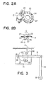
- Figs. 2A and 2B show an arrangement of the steering wheel angle sensor 2 in which Fig. 2A shows a perspective view thereof and Fig. 2B shows a front view thereof illustrating the relationship of light switches 21, 22 and a circular slit plate 27 having a plurality of slits or apertures 24 circumferentially formed therethrough.
- the light switches 21 and 22 respectively comprise a set of a photo-transistor 25 and an LED 26, each set forming a light switch called a photo-interrupter.
- the plate 27 With the slit plate 27 being rotated due to the steering operation of the stearing wheel of the car, the plate 27 traverses the light switches, whereby the light switche 21 or 22 is switched on while an aperture 24 of the plate 27 passes under the light switch 21 or 22, and is otherwise switched off while a mask portion 23 of the slit plate 27 between the apertures 24 passes under the light switch 21 or 22 to cause photo-interruption of the respective light sources.
- the plate 27 is mounted on a shaft 13 of a steering wheel 12 so as to rotate according to the rotation of the steering wheel 12.
- Fig. 3 shows an arrangement of the vehicle height sensor 14 in which the rod 15 connects to the vehicle wheel 7 through the arm 8 and an arm 16 connecting the arm 15 and the sensor 14 rotates about point 14a depending on the variation of the vehicle height.
- the rotation of the arm 16 causes a slit plate 37 connected to the arm 16 to rotate.
- Light switches 34, 35, and 36 each formed of the photo-interrupter provide as outputs therefrom on/off signals in accordance with a pattern of photo passage or photo interruption generated by the rotation of the slit plate 37.
- vehicle height sensors 14a and 14b mounted on the vehicle body 4 is shown in Fig. 4 together with vehicle wheels 41, 42, 43, and 44.
- the sensors 14a and 14b being thus mounted symmetrically in relation to the front and the rear wheels, not only variations in the vehicle's front height as well as the vehicle's rear height but also the presences of a body rolling in the lateral direction as well as a body pitching in the longitudinal direction can be detected simultaneously. It is obvious that if four vehicle height sensors are mounted respectively on the four wheels, then a more precise height information will be obtained compared with the case of two sensors as illustrated.
- Fig. 5 shows an output waveform of the vehicle speed sensor 3.
- the on/off output signal of the lead switch 3a which is waveform-shaped so as to filter therefrom chattering noises etc., has the following characteristic.
- a component due to a manufacturing precision such as eccentricity etc., of the magnet 3b may give rise to an error in each period of tl, t2, t3, and t4.
- a second component is introduced due to rotational variations by the wire 3c as a function of time which gives rise to fluctuations in the generated pulse periods tl, t2, t3, ---, tn.
- the optimum method of calculating the vehicle's speed with accuracy and with good responsiveness is to determine tlO, tll, and tl3 and then to calculate the vehicle speed from their inverse numbers.
- the average value of t2, t3, t4 and t5 are determined whereby the vehicle speed is determined from the average value.
- This method realizes the calculation and determination of the vehicle's speed with accuracy and with good responsiveness. It is needless to say that such an averaging process calculation may readily be realized by employing a micro-computer as the control unit 1 by counting the periods of tl, t2, ---, tn each time pr edge of a pulse is inputed, and by storing in a memory the periods tl, t2, ---, tn. It is also needless to say that the calculation of the vehicle's speed per se must not necessarily be determined per one cycle of rotation but the average value of the periods for a number of cycles may be used for the various determination, the coordinates of a map for the determination, and the coordinates of the interpolation calculation for the map for the various determinations, in this invention.
- Fig. 6 shows waveforms SW1 and SW2 detected by the steering wheel angle sensor 2 shown in Figs. 1 and 2.
- the waveforms SW1 and SW2 are respectively provided as output pulse signals from the light switches 21 and 22 of the sensor 2 at a rate of one pulse each time the steering wheel 12 is rotated by 30°, and have output pulse edges of a-c-a-c and b-d-b-d, respectively for the case where the steering wheel is rotated in the clockwise (C.W.) direction. It is to be noted that the period of these pulses corresponds to the rotating speed of the steering wheel 12.
- FIG. 6 illustrates the case where the steering wheel is initially rotated in the clockwise direction at a uniform rate after which it is rotated in a counterclockwise (C.C.W.) direction at a uniform rate just after a pulse edge "a" of SW1 has risen.
- C.C.W. rotation by monitorizing the order in which the pulse edges are generated, i.e. a-b-c-d for C.W. rotation and a-d-c-b for C.C.W. rotation, a change in the of direction rotation can be detected.
- the variation of the steering wheel angular velocity can be continuously measured, and by integrating the angle of 30 0 /4 per inter-pulse edges of a-b, b-c, and so on during the forward rotation, the total steering wheel angle can be detected.
- the steering wheel's rotation is C.C.W. and by calculating the steering wheel angular velocity or the total steering wheel angle momently from the periods of Pll, P12, P13, P14 and so on as shown in Fig. 6, it is possible to detect the steering wheel angular velocity and the steering wheel angle per se in the C.C.W. rotation as in the C.W. rotation.
- the steering wheel angular velocity and the total steering wheel angle can be updated every 30 0 /4, i.e., during the period Pl, then the period P2, then the period P3, and so on in this embodiment, a highly accurate detection of the steering wheel angle having a good responsive can be achieved.
- steering wheel angle sensor 2 providing as an output therefrom one pulse each time the steering wheel is rotated by 30°
- a steering wheel sensor may be of a type which issues one pulse per any number of degrees or may be an analog type which is also capable of detecting the direction of rotation.
- the acceleration sensor 17 may be of the type which provides as an output therefrom an analog signal representative of the acceleration of a vehicle in the lateral direction thereof or may be of the type which only indicates the presence or absence of the acceleration above a predetermined threshold value in the form of a code "1" or "0", respectively.
- Fig. 7 showing a program flow chart stored in a memory of a micro-computer forming the control unit 1 of the embodiment of this invention in Fig. 1.
- the main routine of the electronic controlled suspension is started at Step 71.
- the present vehicle speed is calculated from the output of the vehicle speed sensor 3 using the calculation method described with reference to Fig. 5, namely, the average value of the periods of the vehicle speed pulses is determined and from this average value the vehicle speed is determined.
- a threshold value based on the steering wheel angular velocity and the vehicle's speed as calculated at Step 72 is calculated.
- This threshold value is selected such that the steering wheel angle can be judged to be a sharp steering operation for a low vehicle's speed as well as for a slow steering operation to some extent for a high vehicle speed.
- Step 74 a comparison is made between the above threshold value (judging value) of the steering wheel angular velocity and the present steering wheel angular velocity, and if the steering wheel angular velocity is larger than the threshold value, indicating that the vehicle begins to turn sharply, the program proceeds to Step 75 whereby operations for changing over the suspension to the "HARD" mode will be executed.
- an initial value is set in a first timer not shown but included in the control unit 1 which is supposed to count down per a predetermined time interval and to be clipped at zero count by a timer routine (not shown). For example, if a count value corresponding to 2 seconds is set in the timer, the timer is counted down per e.g. 10 ms whereby the count value becomes zero in 2 seconds at which time it is determined as "count-over”.
- the suspension is made "HARD" and then the program returns to the start at Step 71.
- Step 77 the steering direction is confirmed, and at Step 78 the rolling direction which is expected from the steering direction is calculated.
- Step 79 the outputs or the average value of the outputs of the vehicle height sensors 14 mounted on four wheels or only the front and rear wheels on the diagonal line is confirmed. For example, in the case of the right turning, the vehicle is rolled in the left-hand direction. In this case, the height of the vehicle's right front wheel is extended while the height of the vehicle's left rear wheels is reduced so that the outputs of the vehicle height sensors 14 are mutually displaced in the opposite directions.
- Step 80 it is judged that if the outputs of the vehicle height sensors 14 on the diagonal line or the average values thereof have a variation in the opposite directions and indicate the same rolling direction as that expected from the steering direction determined from the steering wheel angle sensor 2, the turning has commenced. If it is judged at Step 80 that the vehicle is rolling in the expected direction, the program proceeds to Step 75 in which the suspension characteristic is made "HARD" as mentioned above. Otherwise, the program goes to the next Step 81.
- the acceleration sensor 17 is used to detect the acceleration of the vehicle in the lateral direction, whereby when an acceleration value G exceeds a first (higher) prescribed value, the commencement of the turning is judged. For this purpose, at Step 81 it is checked whether or not the higher prescribed value G is exceeded, and if it is exceeded, then it is judged that the turning has commenced whereby the program proceeds to Step 75 where the control unit 1 causes the suspension characteristic to change to be "HARD" as above noted. Otherwise, the program proceeds to the next Step 82.
- Step 90 if any of the above conditions on the commencement of the turning is met, the first timer is preset at Step 75 and the suspension characteristic is made "HARD". Also, if any of the conditions is met continuously, then the first timer is always preset to change over the spring characteristic and the damping force of the suspension into the "HARD" mode. If not met continuously, the first timer will not be preset, the first timer is counted down per a predetermined time interval and counted down to zero when a prescribed time interval has lapsed, thereby being clipped, as mentioned before. Of course, if none of the above conditions is met, the suspension characteristic is maintained "SOFT" and the timer remains reset at a zero count.
- the steering direction which has caused the commencement of the turning can be stored in the memory. On the basis of this stored steering direction, the present steering direction is confirmed. Namely it is confirmed at Step 82 whether or not the present steering direction has reversed. If it is determined that the steering direction has not reversed, the program proceeds to Step Sl without doing anything. In this case, it is determined that the turning mode has not been completed. If reversed, it is confirmed at Step 83 whether or not the steering wheel has been returned by a predetermined angle or more in the reverse direction, or whether or not the steering wheel has been returned at a predetermined rate or more in the reverse direction.
- Step 84 it is checked whether or not the first timer has counted over. If "yes”, the suspension characteristic is restored to "SOFT * at Step 89 and then the program returns to Step 71. If none of the above mentioned both conditions are met, it is deemed during the turning that the conditions are still being checked while it is deemed outside of the turning that the conditions remain unchanged and the program proceeds to the predetermined step.
- Step 85 the outputs of the sensors 14 or the average values thereof are read in, and if it is determined at Step 86 that the outputs of the sensors 14 do not coincide with each other indicating that the rolling has not ceased, the program proceeds to the next step with the suspension characteristic being maintained "HARD". On the other hand, if it is determined that the outputs of the sensors 14 coincide with each other indicating that the rolling has ceased, the turning mode is determined to be completed and the program proceeds to Step 84. Step 84 and the following steps are as mentioned above.
- Step 87 It is checked at Step 87 whether or not the G value of the vehicle is smaller than a second prescribed G value which is lower by a desired value than the first prescribed value used for the determination of the commencement of the turning. If the former is found to be smaller than the latter, it is determined that the turning has been completed, and the program proceeds to Step 84. Otherwise, the program proceeds to the next step 88.
- the determination of the first and second prescribed G values can be made by using multi-determination points in the case of an analog type G sensor and that also in the case of a G sensor of a single output type (0,1) the hysteresis may be set to a desired value such that a point at which the output of the G sensor is turned on corresponds to the first prescribed G value and a point at which the output of the G sensor is turned off corresponds to the second prescribed G value.
- Step 88 if it is determined that the vehicle speed has become lower than the prescribed value, for example, the vehicle has stopped, then it may be considered that the turning or the rolling due to the turning has been completed, and therefore, the program proceeds to Step 84. Otherwise, the program returns to Step 71 of "start".
- the setting time of the first timer is modified to a programmed desirable value according to information from various sensors indicative of the operating condition of a vehicle such as vehicle information of the vehicle height sensor, G information of the acceleration sensor, gear position information of the transmission, braking information, and information of a throttle opening sensor, the change-over timing between the "HARD” and the “SOFT” modes and the change-over frequency can be programmed in the optimum condition, advantageously resulting in a comfortable and durable suspension.
Landscapes
- Engineering & Computer Science (AREA)
- Mechanical Engineering (AREA)
- Vehicle Body Suspensions (AREA)
Applications Claiming Priority (2)
| Application Number | Priority Date | Filing Date | Title |
|---|---|---|---|
| JP58768/84 | 1984-03-27 | ||
| JP59058768A JPS60203510A (ja) | 1984-03-27 | 1984-03-27 | 自動車の懸架装置 |
Publications (3)
| Publication Number | Publication Date |
|---|---|
| EP0157576A2 true EP0157576A2 (fr) | 1985-10-09 |
| EP0157576A3 EP0157576A3 (en) | 1987-11-25 |
| EP0157576B1 EP0157576B1 (fr) | 1991-10-30 |
Family
ID=13093723
Family Applications (1)
| Application Number | Title | Priority Date | Filing Date |
|---|---|---|---|
| EP85302072A Expired - Lifetime EP0157576B1 (fr) | 1984-03-27 | 1985-03-26 | Système de suspension pour véhicule automobile |
Country Status (6)
| Country | Link |
|---|---|
| US (1) | US4624477A (fr) |
| EP (1) | EP0157576B1 (fr) |
| JP (1) | JPS60203510A (fr) |
| KR (1) | KR890002119B1 (fr) |
| AU (1) | AU555995B2 (fr) |
| DE (1) | DE3584533D1 (fr) |
Cited By (7)
| Publication number | Priority date | Publication date | Assignee | Title |
|---|---|---|---|---|
| EP0215315A2 (fr) | 1985-09-14 | 1987-03-25 | Robert Bosch Gmbh | Suspension pour véhicules |
| EP0227343A1 (fr) | 1985-12-16 | 1987-07-01 | Ford Motor Company Limited | Système de commande pour suspension réglable |
| DE3830168A1 (de) * | 1987-09-04 | 1989-03-16 | Mitsubishi Motors Corp | Fahrzeugaufhaengung |
| US4853860A (en) * | 1987-11-18 | 1989-08-01 | Ford Motor Company | Control system for adjustable automotive suspension unit |
| EP0285153A3 (en) * | 1987-03-31 | 1990-01-10 | Nissan Motor Co., Ltd. | Actively controlled automotive suspension system with acceleration and angular velocity dependent anti-pitching and/or anti-rolling feature |
| EP0424843A1 (fr) * | 1989-10-24 | 1991-05-02 | Matsushita Electric Industrial Co., Ltd. | Dispositif de contrôle de suspension |
| DE10032079A1 (de) * | 2000-07-01 | 2002-01-10 | Volkswagen Ag | Verfahren und Vorrichtung zur Dämpferregelung eines Fahrzeuges |
Families Citing this family (30)
| Publication number | Priority date | Publication date | Assignee | Title |
|---|---|---|---|---|
| JPS6130406A (ja) * | 1984-07-20 | 1986-02-12 | Kayaba Ind Co Ltd | アンチロ−ル制御装置 |
| JPS6130407A (ja) * | 1984-07-20 | 1986-02-12 | Kayaba Ind Co Ltd | アンチロ−ル制御装置 |
| JPS61275053A (ja) * | 1985-05-31 | 1986-12-05 | 財団法人鉄道総合技術研究所 | 車両の振動制御装置 |
| JP2532059B2 (ja) * | 1985-09-13 | 1996-09-11 | 日産自動車株式会社 | 車両のサスペンシヨン制御装置 |
| US4693493A (en) * | 1985-10-22 | 1987-09-15 | Toyota Jidosha Kabushiki Kaisha | System for vehicle body roll control utilizing steering angle detection |
| JPH0710643B2 (ja) * | 1985-10-22 | 1995-02-08 | トヨタ自動車株式会社 | 車輌用車高調整装置 |
| JPS6292907U (fr) * | 1985-12-02 | 1987-06-13 | ||
| JPH0737203B2 (ja) * | 1986-05-08 | 1995-04-26 | 日産自動車株式会社 | 車高制御装置 |
| JPS62299418A (ja) * | 1986-06-20 | 1987-12-26 | Tokico Ltd | 車両用サスペンシヨンの制御装置 |
| JPH0741784B2 (ja) * | 1986-11-28 | 1995-05-10 | 日産自動車株式会社 | サスペンシヨンとステアリングの総合制御装置 |
| JPH0829648B2 (ja) * | 1987-03-16 | 1996-03-27 | 日産自動車株式会社 | 車両用サスペンシヨン制御装置 |
| JPS63189705U (fr) * | 1987-05-27 | 1988-12-06 | ||
| US5159554A (en) * | 1987-07-06 | 1992-10-27 | Toyota Jidosha Kabushiki Kaisha | Electronic controlled fluid suspension system |
| JPH069846Y2 (ja) * | 1987-11-05 | 1994-03-16 | 三菱自動車工業株式会社 | アクテイブサスペンシヨン制御装置 |
| US5053671A (en) * | 1987-11-16 | 1991-10-01 | Nissan Motor Company, Limited | Piezoelectric sensor for monitoring kinetic momentum |
| JPH02280694A (ja) * | 1989-04-21 | 1990-11-16 | Mitsubishi Electric Corp | アクチュエータ制御回路 |
| US5120982A (en) * | 1989-11-14 | 1992-06-09 | Ford Motor Company | Fault correcting circuit |
| US5080392A (en) * | 1990-04-26 | 1992-01-14 | Cb Auto Design Inc. | Suspension unit |
| US5979616A (en) * | 1993-07-12 | 1999-11-09 | Cloud Farm Associates, L.P. | Tilt control apparatus for vehicles |
| AUPN384395A0 (en) * | 1995-06-27 | 1995-07-20 | Kinetic Limited | Control method for vehicle suspension system |
| GB9818269D0 (en) | 1998-08-22 | 1998-10-14 | Rover Group | Vehicle suspensions |
| JP3988704B2 (ja) * | 2003-09-26 | 2007-10-10 | アイシン・エィ・ダブリュ株式会社 | 車両のサスペンション制御システム及び制御方法 |
| GB2406548A (en) * | 2003-10-03 | 2005-04-06 | Trelleborg Ab | Air suspension system |
| KR100656084B1 (ko) * | 2004-12-21 | 2006-12-08 | 주식회사 만도 | 차량의 전복 방지를 위한 댐퍼 제어방법 |
| US7370853B2 (en) | 2005-03-31 | 2008-05-13 | Delphi Technologies, Inc. | Vibration isolating bushing with embedded angular position sensor |
| US7360756B2 (en) * | 2005-03-31 | 2008-04-22 | Delphi Technologies, Inc. | Vibration isolating bushing with embedded speed/position sensor |
| US20060220638A1 (en) * | 2005-03-31 | 2006-10-05 | Urquidi Carlos A | Angular position sensor |
| JP4333660B2 (ja) * | 2005-10-07 | 2009-09-16 | トヨタ自動車株式会社 | ロール角制御とロール剛性前後配分比制御を組み合わせた車輌 |
| DE102006017899A1 (de) * | 2006-04-13 | 2007-10-25 | Daimlerchrysler Ag | Verfahren und Vorrichtung zur Beeinflussung des Fahrverhaltens eines Fahrzeuges |
| CN116373523B (zh) * | 2023-05-11 | 2025-10-17 | 重庆长安汽车股份有限公司 | 空气弹簧高度调节方法、装置、设备及存储介质 |
Family Cites Families (13)
| Publication number | Priority date | Publication date | Assignee | Title |
|---|---|---|---|---|
| IT939885B (it) * | 1971-09-25 | 1973-02-10 | Fiat Spa | Sistema di comando per sospensio ni indipendenti di autoveicoli |
| DE2736026C2 (de) * | 1976-08-19 | 1985-10-24 | Honda Giken Kogyo K.K., Tokio/Tokyo | Hydropneumatische Federung für Fahrzeuge |
| JPS5858242B2 (ja) * | 1980-01-16 | 1983-12-24 | 日産自動車株式会社 | 車高調整装置 |
| GB2097344B (en) * | 1981-04-08 | 1984-05-16 | Lucas Ind Plc | Self-leveling suspension system |
| JPS57182505A (en) * | 1981-05-01 | 1982-11-10 | Kayaba Ind Co Ltd | Antiroll system of vehicle |
| JPS6127293Y2 (fr) * | 1981-06-19 | 1986-08-14 | ||
| JPS58167210A (ja) * | 1982-03-26 | 1983-10-03 | Nippon Denso Co Ltd | シヨツクアブソ−バ制御方式 |
| JPS5923712A (ja) * | 1982-07-30 | 1984-02-07 | Hino Motors Ltd | エアサスペンシヨン装置 |
| US4555126A (en) * | 1982-10-18 | 1985-11-26 | Mazda Motor Corporation | Vehicle suspension system |
| US4506751A (en) * | 1982-12-21 | 1985-03-26 | Applied Power Inc. | Tilt cab truck with anti-dive and anti-sway control |
| JPS59120509A (ja) * | 1982-12-27 | 1984-07-12 | Toyota Motor Corp | 車両のサスペンシヨン機構におけるシヨツクアブソ−バの減衰力制御装置 |
| JPS59147107A (ja) * | 1983-02-10 | 1984-08-23 | 三井造船株式会社 | 2個のハニカム板の接続方法 |
| JPS60128011A (ja) * | 1983-12-12 | 1985-07-08 | Nissan Motor Co Ltd | 車両におけるロ−ル剛性制御装置 |
-
1984
- 1984-03-27 JP JP59058768A patent/JPS60203510A/ja active Pending
-
1985
- 1985-02-13 KR KR1019850000872A patent/KR890002119B1/ko not_active Expired
- 1985-03-20 US US06/713,756 patent/US4624477A/en not_active Expired - Lifetime
- 1985-03-26 EP EP85302072A patent/EP0157576B1/fr not_active Expired - Lifetime
- 1985-03-26 AU AU40388/85A patent/AU555995B2/en not_active Ceased
- 1985-03-26 DE DE8585302072T patent/DE3584533D1/de not_active Expired - Lifetime
Cited By (11)
| Publication number | Priority date | Publication date | Assignee | Title |
|---|---|---|---|---|
| EP0215315A2 (fr) | 1985-09-14 | 1987-03-25 | Robert Bosch Gmbh | Suspension pour véhicules |
| EP0215315A3 (en) * | 1985-09-14 | 1987-06-03 | Robert Bosch Gmbh | Suspension for vehicles |
| EP0227343A1 (fr) | 1985-12-16 | 1987-07-01 | Ford Motor Company Limited | Système de commande pour suspension réglable |
| EP0227343B2 (fr) † | 1985-12-16 | 1994-09-28 | Ford Motor Company Limited | Système de commande pour suspension réglable |
| EP0285153A3 (en) * | 1987-03-31 | 1990-01-10 | Nissan Motor Co., Ltd. | Actively controlled automotive suspension system with acceleration and angular velocity dependent anti-pitching and/or anti-rolling feature |
| DE3830168A1 (de) * | 1987-09-04 | 1989-03-16 | Mitsubishi Motors Corp | Fahrzeugaufhaengung |
| US4853860A (en) * | 1987-11-18 | 1989-08-01 | Ford Motor Company | Control system for adjustable automotive suspension unit |
| EP0317071A3 (en) * | 1987-11-18 | 1990-10-03 | Ford Motor Company Limited | Control system for adjustable automotive suspension unit |
| EP0424843A1 (fr) * | 1989-10-24 | 1991-05-02 | Matsushita Electric Industrial Co., Ltd. | Dispositif de contrôle de suspension |
| US5102162A (en) * | 1989-10-24 | 1992-04-07 | Matsushita Electric Industrial Co., Ltd. | Suspension control apparatus |
| DE10032079A1 (de) * | 2000-07-01 | 2002-01-10 | Volkswagen Ag | Verfahren und Vorrichtung zur Dämpferregelung eines Fahrzeuges |
Also Published As
| Publication number | Publication date |
|---|---|
| DE3584533D1 (de) | 1991-12-05 |
| EP0157576A3 (en) | 1987-11-25 |
| KR850006339A (ko) | 1985-10-05 |
| KR890002119B1 (ko) | 1989-06-20 |
| US4624477A (en) | 1986-11-25 |
| EP0157576B1 (fr) | 1991-10-30 |
| AU4038885A (en) | 1985-10-03 |
| JPS60203510A (ja) | 1985-10-15 |
| AU555995B2 (en) | 1986-10-16 |
Similar Documents
| Publication | Publication Date | Title |
|---|---|---|
| EP0157576B1 (fr) | Système de suspension pour véhicule automobile | |
| EP0174772B1 (fr) | Système de régulation du niveau pour un véhicule | |
| EP0227343B2 (fr) | Système de commande pour suspension réglable | |
| CA2201196C (fr) | Methode pour determiner la position de la direction d'un mecanisme de direction automobile | |
| US5787375A (en) | Method for determining steering position of automotive steering mechanism | |
| EP0115202B1 (fr) | Système de commande pour amortisseurs de choc | |
| US4722545A (en) | Method and apparatus for determining the center position of a vehicular steering system | |
| US5127667A (en) | Suspension control apparatus | |
| US4867466A (en) | Distance based method and apparatus for determining the center position of a vehicular steering system | |
| US5161816A (en) | Suspension control apparatus | |
| GB2281722A (en) | Controlling damping characteristic of vehicular shock absorber | |
| US6498971B2 (en) | Apparatus for determining steer angle of a motor vehicle | |
| JP2836832B2 (ja) | 自動車のステアリング機構に於るステアリング位置を決定する方法及び装置 | |
| US4674587A (en) | Control apparatus for power steering system | |
| EP0424843B1 (fr) | Dispositif de contrÔle de suspension | |
| JPH0569003B2 (fr) | ||
| JPS6050010A (ja) | 自動車の懸架装置 | |
| JPH03215751A (ja) | 車両の加速度演算装置 | |
| JPS6161005A (ja) | 車両の操舵角検出装置 | |
| JPH05330326A (ja) | サスペンション制御装置 | |
| JPS63195078A (ja) | 車両のサスペンシヨン制御装置 |
Legal Events
| Date | Code | Title | Description |
|---|---|---|---|
| PUAI | Public reference made under article 153(3) epc to a published international application that has entered the european phase |
Free format text: ORIGINAL CODE: 0009012 |
|
| AK | Designated contracting states |
Designated state(s): DE FR GB |
|
| PUAL | Search report despatched |
Free format text: ORIGINAL CODE: 0009013 |
|
| AK | Designated contracting states |
Kind code of ref document: A3 Designated state(s): DE FR GB |
|
| 17P | Request for examination filed |
Effective date: 19880318 |
|
| 17Q | First examination report despatched |
Effective date: 19880629 |
|
| GRAA | (expected) grant |
Free format text: ORIGINAL CODE: 0009210 |
|
| AK | Designated contracting states |
Kind code of ref document: B1 Designated state(s): DE FR GB |
|
| REF | Corresponds to: |
Ref document number: 3584533 Country of ref document: DE Date of ref document: 19911205 |
|
| REG | Reference to a national code |
Ref country code: GB Ref legal event code: 727 |
|
| ET | Fr: translation filed | ||
| REG | Reference to a national code |
Ref country code: GB Ref legal event code: 727A |
|
| REG | Reference to a national code |
Ref country code: GB Ref legal event code: 727B |
|
| REG | Reference to a national code |
Ref country code: GB Ref legal event code: SP |
|
| PLBE | No opposition filed within time limit |
Free format text: ORIGINAL CODE: 0009261 |
|
| STAA | Information on the status of an ep patent application or granted ep patent |
Free format text: STATUS: NO OPPOSITION FILED WITHIN TIME LIMIT |
|
| 26N | No opposition filed | ||
| PGFP | Annual fee paid to national office [announced via postgrant information from national office to epo] |
Ref country code: FR Payment date: 20010313 Year of fee payment: 17 |
|
| PGFP | Annual fee paid to national office [announced via postgrant information from national office to epo] |
Ref country code: DE Payment date: 20010319 Year of fee payment: 17 |
|
| PGFP | Annual fee paid to national office [announced via postgrant information from national office to epo] |
Ref country code: GB Payment date: 20010321 Year of fee payment: 17 |
|
| REG | Reference to a national code |
Ref country code: GB Ref legal event code: IF02 |
|
| PG25 | Lapsed in a contracting state [announced via postgrant information from national office to epo] |
Ref country code: GB Free format text: LAPSE BECAUSE OF NON-PAYMENT OF DUE FEES Effective date: 20020326 |
|
| PG25 | Lapsed in a contracting state [announced via postgrant information from national office to epo] |
Ref country code: DE Free format text: LAPSE BECAUSE OF NON-PAYMENT OF DUE FEES Effective date: 20021001 |
|
| GBPC | Gb: european patent ceased through non-payment of renewal fee |
Effective date: 20020326 |
|
| PG25 | Lapsed in a contracting state [announced via postgrant information from national office to epo] |
Ref country code: FR Free format text: LAPSE BECAUSE OF NON-PAYMENT OF DUE FEES Effective date: 20021129 |
|
| REG | Reference to a national code |
Ref country code: FR Ref legal event code: ST |