EP0162280B1 - Mécanisme de frein pour une porte automatique - Google Patents
Mécanisme de frein pour une porte automatique Download PDFInfo
- Publication number
- EP0162280B1 EP0162280B1 EP85104584A EP85104584A EP0162280B1 EP 0162280 B1 EP0162280 B1 EP 0162280B1 EP 85104584 A EP85104584 A EP 85104584A EP 85104584 A EP85104584 A EP 85104584A EP 0162280 B1 EP0162280 B1 EP 0162280B1
- Authority
- EP
- European Patent Office
- Prior art keywords
- door
- braking
- speed
- brake
- pulse
- Prior art date
- Legal status (The legal status is an assumption and is not a legal conclusion. Google has not performed a legal analysis and makes no representation as to the accuracy of the status listed.)
- Expired
Links
Images







Classifications
-
- E—FIXED CONSTRUCTIONS
- E05—LOCKS; KEYS; WINDOW OR DOOR FITTINGS; SAFES
- E05F—DEVICES FOR MOVING WINGS INTO OPEN OR CLOSED POSITION; CHECKS FOR WINGS; WING FITTINGS NOT OTHERWISE PROVIDED FOR, CONCERNED WITH THE FUNCTIONING OF THE WING
- E05F15/00—Power-operated mechanisms for wings
- E05F15/60—Power-operated mechanisms for wings using electrical actuators
- E05F15/603—Power-operated mechanisms for wings using electrical actuators using rotary electromotors
- E05F15/632—Power-operated mechanisms for wings using electrical actuators using rotary electromotors for horizontally-sliding wings
-
- E—FIXED CONSTRUCTIONS
- E05—LOCKS; KEYS; WINDOW OR DOOR FITTINGS; SAFES
- E05Y—INDEXING SCHEME ASSOCIATED WITH SUBCLASSES E05D AND E05F, RELATING TO CONSTRUCTION ELEMENTS, ELECTRIC CONTROL, POWER SUPPLY, POWER SIGNAL OR TRANSMISSION, USER INTERFACES, MOUNTING OR COUPLING, DETAILS, ACCESSORIES, AUXILIARY OPERATIONS NOT OTHERWISE PROVIDED FOR, APPLICATION THEREOF
- E05Y2201/00—Constructional elements; Accessories therefor
- E05Y2201/20—Brakes; Disengaging means; Holders; Stops; Valves; Accessories therefor
- E05Y2201/21—Brakes
-
- E—FIXED CONSTRUCTIONS
- E05—LOCKS; KEYS; WINDOW OR DOOR FITTINGS; SAFES
- E05Y—INDEXING SCHEME ASSOCIATED WITH SUBCLASSES E05D AND E05F, RELATING TO CONSTRUCTION ELEMENTS, ELECTRIC CONTROL, POWER SUPPLY, POWER SIGNAL OR TRANSMISSION, USER INTERFACES, MOUNTING OR COUPLING, DETAILS, ACCESSORIES, AUXILIARY OPERATIONS NOT OTHERWISE PROVIDED FOR, APPLICATION THEREOF
- E05Y2201/00—Constructional elements; Accessories therefor
- E05Y2201/20—Brakes; Disengaging means; Holders; Stops; Valves; Accessories therefor
- E05Y2201/25—Mechanical means for force or torque adjustment therefor
-
- E—FIXED CONSTRUCTIONS
- E05—LOCKS; KEYS; WINDOW OR DOOR FITTINGS; SAFES
- E05Y—INDEXING SCHEME ASSOCIATED WITH SUBCLASSES E05D AND E05F, RELATING TO CONSTRUCTION ELEMENTS, ELECTRIC CONTROL, POWER SUPPLY, POWER SIGNAL OR TRANSMISSION, USER INTERFACES, MOUNTING OR COUPLING, DETAILS, ACCESSORIES, AUXILIARY OPERATIONS NOT OTHERWISE PROVIDED FOR, APPLICATION THEREOF
- E05Y2400/00—Electronic control; Electrical power; Power supply; Power or signal transmission; User interfaces
- E05Y2400/10—Electronic control
- E05Y2400/30—Electronic control of motors
- E05Y2400/302—Electronic control of motors during electric motor braking
-
- E—FIXED CONSTRUCTIONS
- E05—LOCKS; KEYS; WINDOW OR DOOR FITTINGS; SAFES
- E05Y—INDEXING SCHEME ASSOCIATED WITH SUBCLASSES E05D AND E05F, RELATING TO CONSTRUCTION ELEMENTS, ELECTRIC CONTROL, POWER SUPPLY, POWER SIGNAL OR TRANSMISSION, USER INTERFACES, MOUNTING OR COUPLING, DETAILS, ACCESSORIES, AUXILIARY OPERATIONS NOT OTHERWISE PROVIDED FOR, APPLICATION THEREOF
- E05Y2400/00—Electronic control; Electrical power; Power supply; Power or signal transmission; User interfaces
- E05Y2400/10—Electronic control
- E05Y2400/32—Position control, detection or monitoring
- E05Y2400/334—Position control, detection or monitoring by using pulse generators
- E05Y2400/336—Position control, detection or monitoring by using pulse generators of the angular type
- E05Y2400/337—Encoder wheels
-
- E—FIXED CONSTRUCTIONS
- E05—LOCKS; KEYS; WINDOW OR DOOR FITTINGS; SAFES
- E05Y—INDEXING SCHEME ASSOCIATED WITH SUBCLASSES E05D AND E05F, RELATING TO CONSTRUCTION ELEMENTS, ELECTRIC CONTROL, POWER SUPPLY, POWER SIGNAL OR TRANSMISSION, USER INTERFACES, MOUNTING OR COUPLING, DETAILS, ACCESSORIES, AUXILIARY OPERATIONS NOT OTHERWISE PROVIDED FOR, APPLICATION THEREOF
- E05Y2400/00—Electronic control; Electrical power; Power supply; Power or signal transmission; User interfaces
- E05Y2400/10—Electronic control
- E05Y2400/36—Speed control, detection or monitoring
-
- E—FIXED CONSTRUCTIONS
- E05—LOCKS; KEYS; WINDOW OR DOOR FITTINGS; SAFES
- E05Y—INDEXING SCHEME ASSOCIATED WITH SUBCLASSES E05D AND E05F, RELATING TO CONSTRUCTION ELEMENTS, ELECTRIC CONTROL, POWER SUPPLY, POWER SIGNAL OR TRANSMISSION, USER INTERFACES, MOUNTING OR COUPLING, DETAILS, ACCESSORIES, AUXILIARY OPERATIONS NOT OTHERWISE PROVIDED FOR, APPLICATION THEREOF
- E05Y2400/00—Electronic control; Electrical power; Power supply; Power or signal transmission; User interfaces
- E05Y2400/10—Electronic control
- E05Y2400/50—Fault detection
- E05Y2400/514—Fault detection of speed
-
- E—FIXED CONSTRUCTIONS
- E05—LOCKS; KEYS; WINDOW OR DOOR FITTINGS; SAFES
- E05Y—INDEXING SCHEME ASSOCIATED WITH SUBCLASSES E05D AND E05F, RELATING TO CONSTRUCTION ELEMENTS, ELECTRIC CONTROL, POWER SUPPLY, POWER SIGNAL OR TRANSMISSION, USER INTERFACES, MOUNTING OR COUPLING, DETAILS, ACCESSORIES, AUXILIARY OPERATIONS NOT OTHERWISE PROVIDED FOR, APPLICATION THEREOF
- E05Y2800/00—Details, accessories and auxiliary operations not otherwise provided for
- E05Y2800/74—Specific positions
-
- E—FIXED CONSTRUCTIONS
- E05—LOCKS; KEYS; WINDOW OR DOOR FITTINGS; SAFES
- E05Y—INDEXING SCHEME ASSOCIATED WITH SUBCLASSES E05D AND E05F, RELATING TO CONSTRUCTION ELEMENTS, ELECTRIC CONTROL, POWER SUPPLY, POWER SIGNAL OR TRANSMISSION, USER INTERFACES, MOUNTING OR COUPLING, DETAILS, ACCESSORIES, AUXILIARY OPERATIONS NOT OTHERWISE PROVIDED FOR, APPLICATION THEREOF
- E05Y2900/00—Application of doors, windows, wings or fittings thereof
- E05Y2900/10—Application of doors, windows, wings or fittings thereof for buildings or parts thereof
- E05Y2900/13—Type of wing
- E05Y2900/132—Doors
Definitions
- This invention relates to a brake apparatus for an automatic door, and more particularly to a brake apparatus which ensures a safe and smooth closing motion of an automatic door.
- An automatic door is generally operated in three basic steps: transfer of the door driven by a motor to a predetermined position a little before the full open or full shut position at a comparatively high speed, deceleration by operating the braking means at leastonce, and transfer to the full open or full shut position at a comparatively low speed.
- Such braking means providing for a three step operation is disclosed, for example, in JP-A-58176791 (58-80082).
- This prior automatic door actuator comprises speed pulse signal output means for providing speed pulse signals at an interval time inversely proportional to the speed of the door, braking means for lowering the door speed, braking position detecting means for detecting the braking position where the braking means starts braking, and brake effect measuring means for measuring the effect of the braking means.
- the braking means When in the prior automatic door actuator the braking means should go out of order, the deceleration of the door might fail; the door speed might change abruptly from high-speed to low-speed; or the door may reach the full open or full shut position while keeping high-speed which applies impact to the door mechanism and may possibly affect components other than the braking means.
- An object of the present invention is to provide a break apparatus for an automatic door which can detect and inform of defects of the braking means. Another object of the invention is to provide a brake apparatus for an automatic door which automatically adjusts the braking power of the braking means so as to maintain smooth motion of the door at all times.
- a brake apparatus for an automatic door comprising:
- a slit disk 6 is attached to the shaft 5 of the motor 4 and a number of slits on the slit disk 6 are detected by a photo-sensor 7 for output of pulse signals.
- the speed pulse signal output is given at a time interval inversely proportional to the transfer speed of the door 2.
- the speed pulse signal output means 8 is composed of the slit disk6 6 and the photo-sensor 7.
- the speed pulse signal output means may also be composed for example, so that pulse signal output is given by detecting the teeth of gears turned by transfer of the door, through magnetic or photoelectric means. It may also be composed of a pulse output mechanism synchronized with the revolution of the motor which drives the door. Other known means may also be used to compose the speed pulse signal output means. In short, it may comprise means by which output of more number of pulses is given as the door speed increases.
- the pulse waveform is not limited so long as it is countable.
- the output of speed pulse signals from the speed pulse signal output means 8 goes into the counter 9 to be counted.
- the counter 9 is cleared by the clear signal from the computer 10.
- This counter 9 comprises the pulse number detecting means.
- the number of pulse signals can also be counted by analog circuit arrangement such as an integrating circuit.
- analog circuit arrangement such as an integrating circuit.
- software means such as a computer program may also be used for pulse signal counting.
- the computer 10 controls operation of the motor 4 through the motor control circuit 11 for open-shut operation of the door 2 and also performs braking by dynamic braking by the motor 4.
- the braking means conventional and known type used in this field is also applicable.
- the duty ratio to operate the braking means may be changed, for example.
- the motor 4 is turned at comparatively high-speed to shut the door 2 rather quickly.
- the motor 4 is operated in a dynamic braking mode for the predetermined braking time (Tb) only, as shown in Fig. 2(b), then operated to free turning mode for the predetermined free time (Tf) only, and the two modes are repeated alternatively.
- Lowering of door speed to a comparatively low level is detected by the counting rate on the counter 9, then the motor 4 is turned at comparatively low speed from the position B to shut the door 2 completely at comparatively low speed.
- the computer 10 is the braking power select means to select adequate braking power through selection of the braking duty ratio, i.e. Tb/(Tb+Tf).
- the door 2 When a powder switch is closed or operator's instruction is given, the door 2 is closed at comparatively low speed to full shut.
- the low speed is to prevent bumping of the door against the door stop when the stroke or the current position of the door 2 is unknown.
- Full shut or not is known by no change of the count on the counter 9.
- the door 2 After the output of a clear signal pulse to clear the counter 9, the door 2 is opened rather slowly to full open.
- the count on the counter 9 at this time indicates the stroke of the door 2.
- the distance corresponding to one count on the counter 9 is determined by the dimensions of the slit disk 6. Accordingly, the computer 10 can recognize the relation between the count and the door position exactly.
- the computer 10 functions to set the pulse signal number to start the operation of the braking means. If, for example, the start position of the braking means is preliminarily instructed to be 200 mm before full shut, the value held on the counter 9 at full open position plus "900" is set as the pulse signal number.
- the pulse signal number is not limited to this setting way but may be set freely corresponding to a desired position within the range from the position that the door can reach at a comparatively high-speed during the closing motion to the predetermined distance before full shut.
- Braking power can be selected as a duty ratio described above. If five steps of duty ratio 15, 12, 8, 6, and 2 are available for selection, for example, the duty ratio is set at 15 in this case. In other words, braking is applied at the maximum braking power. The highest braking power should be in the magnitude that the heaviest door expectable can be stopped at the predetermined position before full shut.
- the counter 9 When stopping of the door 2 is detected through no change of the count on the counter 9, the counter 9 is cleared by the output of clear a signal pulse. Then the door 2 is closed at the comparatively low speed to full shut.
- the count on the counter 9 at this time corresponds to the distance of the closing motion at comparatively low speed. From another point of view, it also corresponds to the distance remained by subtracting the braking distance from the distance of 200 mm position before full shut, which indirectly corresponds to the braking distance.
- the number of pulse signals from oepration of the braking means to stopping of the door corresponds directly to the door braking distance. It may also possible, however, to measure the speed pulse signal which indirectly corresponds to the braking distance as mentioned above.
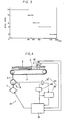
- the computer 10 selects the duty ratio for the next operation according to the count on the counter 9 obtained during the closing operation of comparatively low speed at this time. If the count is "55" and the selection standard shown in Fig. 3 is memorized in the memory as a table, for example, the count "55" corresponds to 110 mm and a duty ratio of 8 is selected.
- next braking is applied at a duty ratio of 8. Since the braking power is smaller than that of the duty ratio 15, the braking distance becomes longer and the distance of closing at comparatively low speed becomes shorter on the contrary.
- the braking effect is larger provided that the braking power is constant, and the door 2 comes to a stop faster. Accordingly, the above count becomes larger. As shown in Fig. 3, however, the duty ratio becomes smaller as the count gets larger. Accordingly, the braking power becomes lower and the braking effect of the next time is smaller.
- the braking distance is kept approximately constant, after all with no regard to door weight.
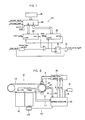
- the automatic door 31 shown in Fig. 4 includes the door 2, belt 3, motor 4, rotary shaft 5, slit disk 6, photo-sensor 7, and speed pulse signal output means 8 similar to those of the above automatic door 1.
- the output of speed pulse signal from the speed pulse signal output means 8 goes into the counter 33 through the gate 32 to be counted.
- the gate 32 is opened during the period from the time when the time is turned to ON by the start signal from the computer 36to the time when the timer 34 returns to OFF after a predetermined time, while the counter 33 is cleared by the above mentioned start signal.
- the count on the counter 33 therefore, is equal to the number of pulse signals during the predetermined time after output of the start signal from the computer 36.
- the gate 32, counter 33 and timer 34 comprise the pulse number detecting means 35.
- the computer 36 is the means for controlling open-shut operation of the door 2 by controlling the motor 4 and the means for braking to apply dynamic braking of the motor 4.
- the motor 4 is first turned at comparatively high-speed to shut the door 2 rather quickly.
- the motor 4 is turned to dynamic braking mode for the braking time (Tb) only as shown in Fig. 5(b), then is turned to free revolution mode for the predetermined free time (Tf), and the modes are repeated alternatively.
- the motor 4 is turned at comparatively low speed to completely shut the door 2 at low-speed.
- the computer 36 gives output of start signal to the counter 33 and thetimer34when the end of the door 2 is detected by the 1 st door position sensor 37.
- Fig. 6 shows transfer characteristics of an over weighted door, adequate weight door, and under weighted door respectively by characteristic curve I, m, and n, when the braking duty ratio (Tb/ (Tb+Tf)) is taken constant.
- the door 2 is closed at comparatively high speed. Since the motor 4 is controlled by the computer 36 to a fixed rate of revolution at this time, the speed i.e. the gradient of the curve is constant with no regard to doorweight, and thetimeto forthe door 2 to reach the 1st door position sensor 37 is constant.
- Section A-B is for braking where the door 2 is intermittently subjected to braking. Since the braking effect is lower with heavier door, a heavy door is not decelerated sufficiently and reaches the 2nd door position sensor 38 within a short time, while a light door is decelerated quickly and takes a long time before reaching the 2nd door position sensor 32. Accordingly, the time to reach the 2nd door position sensor 38 is in the order of t1, t2, t3 becoming longer for heavier doors.
- section B-C the door 2 is closed at comparatively low speed. Since the motor4 is controlled by the computer 36 to a certain rate of revolution, the speed, i.e. the gradient of the curve is constanted with no regard to door weight, and the required time for this section is also constant. Accordingly, the time for the door to full shut, t4, t5, t6, is in the same order as the time t1, t2, and t3.
- the number of pulse K1 during the time of transfer by distance N1 shown in Fig. 6 is to be counted by the counter 33 with overweighted doors. With doors of an adequate weight, the number of pulse K2 during the transfer distance N2 is counted, and with underweighted doors, the number of pulse K3 during the transfer distance N3 is to be counted.
- the computer 36 compares the count K on the counter 33 with the value D at the end of each closing motion. If K>D, the value of Tb/(Tb+Tf) is increased a little and if K ⁇ D, the value is slightly decreased.
- the braking time Tb is extended a little and free time Tf is shortened slightly so that the total time Tb+Tf is kept unchagned, thus the duty ratio of Tb/ (Tb+Tf) is incresaed a little.
- Fig. 5(c) shows this arrangement and the extended braking time and the shortened free time are respectively indicated by Tb' and Tf'. Since during the next closing operation the door is braked with this slightly increased duty ratio, the braking effect is intensified a little and the obtained count is closer to K2.
- the computer 36 automatically controls the duty ratio of braking at every closing operation and the count K is adjusted closer to the setting value D. Accordingly, the door 2 can perform the specified smooth operation, such as shown by the performance curve m in Fig. 6 for example, after closing operations of several times and with no regard to door weight and other conditions.
- the duty ratio is controlled by software arrangement by the computer.
- Hardware arrangement also possible by using such as comparator and so on.
- any arrangement is possible if it functions to operate the braking means intermittently by increasing the duty ratio when the number of pulse signals detected during the braking operation at a certain duty ratio is higher than the predetermined value and by decreasing the duty ratio if it is lower than the predetermined value.
- Fig. 7 is an example of duty ratio adjusting means composed of hardware circuits, which can reduce the work of the microcomputer 36 when installed between the microcomputer 36 and the motor 4.
- the flip-flop 21 When a brake signal input is given to the duty ratio adjusting means 20, the flip-flop 21 is set by the leading edge of the brake signal, and the brake drive signal by the braking means is turned to ON through the AND gate 22.
- an inverted output of the time setting counter 25 is set onto the ON time counter 23.
- the ON time counter 23 outputs a carry signal, when the clock pulse is counted to the retained value on the time setting counter 25, and the carry signal resets the flip-flop 21. Then the brake drive signal is turned to OFF.
- the ON time of the brake/drive signal is the Tb time in Fig. 5 and corresponds to the retained value on the time setting counter 25.
- the OFF time of the brake/drive signal is the Tf time in Fig. 5 and corresponds to the value remained by subtracting the retained value from full counter on the time setting counter 25 (i.e. the above mentioned complement). If the retained number on the time setting counter 25 is increased by input of an upcount signal, the ON time is extended and the OFF time is shortened on the contrary. In other words, the duty ratio is increased. If the retained number on the time setting counter 25 is decreased by input of a down-count signal, the ON time is shortened and the OFF time is extended. The duty ratio is lowered.
- the microcomputer 36 shown in Fig. 4, for example, can adjust the duty ratio by output of brake signal, up-count signal and down-count signal to such circuit 20.
- the value set onto the initial setting switch 26 is set onto the time setting counter 25.
- the duty ratio may be adjusted more than once in one closing operation.
- Another embodiment comprises means to judge door position from the number of speed pulse signals like the above described automatic door 1, so as to eliminate the door position sensor.
- Control of the above brake apparatus is applicable to braking of the automatic door in opening operation. It is also possible, without saying, to apply the duty ratio obtained for closing operation to the next opening operation or vice versa.
- the desired smooth door motion is ensured at all times for this automatic door 31 because operation of the braking means is adjusted automatically according to changes in the conditions.
- the door 42 is fixed to the belt 43 and is moved by the motor 44 through the belt 43.
- the 1st limit switch LS1 When the door 42 is between the position of a little before full open and the position of full open, the 1st limit switch LS1 is turned to ON. While the door 42 is between the position of a little before full shut and the position of full shut, the 2nd limit switch LS2 is turned to ON.
- the speed pulse signal output means 45 is to give output of a speed pulse signal Q1 synchronizing with revolution of the motor 44, i.e. the output of speed pulse signal Q1 by every specified transfer of the door.
- the time interval of the speed pulse signal Q1 is inversely proportional to transfer speed of the door 42.
- the interval of adjacent speed pulse signals Q1 corresponds to 3 mm movement of the door 42.
- the speed pulse signal output means 45 also provide output of speed pulse signal Q2.
- the speed pulse signal Q2 is basically similar to the above speed pulse signal Q1 but the phase is different.
- the motor drive control unit 46 receives the motorturning direction signal f1 and speed signals f2 from the central control unit 50 and gives the output of motor drive signal d according to the received signals to operate the motor 44 at any operating mode, high-speed open (door speed V1), low-speed open (door speed V2), high-speed shut (door speed V3), low-speed shut (door speed V4), pressing (generation of faint pressing torque T in close direction), or free (torque 0).
- the motor drive control unit 46 also receives brake signal f3 from the central control unit 50 and gives the output of braking signal b based on the received brake signal to brake revolution of the motor 44.
- the alarm 47 receives alarm signal a1 from the central control unit 50 and gives alarm to the operator by lamp flashing or buzzer sounding.
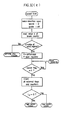
- Fig. 9 shows a detailed circuit of the central control unit.
- the pulse interval detect means to detect the time interval of the speed pulse signal Q1 is composed of the leading edge one-shot circuit 52 into which the input of speed pulse signal Q1 is given and of the speed counter 53 into which the output of the leading edge one-shot circuit 52 is supplied through the delay circuits 66, 67, and the time interval of quotient which divides Q1 by clock cycle is the maximum output of the speed counter 53.
- low-speed open flag 57 set at "1” means that the door speed is equal to or lower than the speed of low-speed open.
- low-speed close flag 58 set at "1” means that the door speed is equal to or lower than the speed of low-speed shut.
- Setting of stop flag 59 at "1" means that the door speed is equal to or below 1.0 mm/sec. Door speed of normal transfer, however, can never be lower than 10 mm/sec., this means detection of stopping of the door 42.
- the stop flag 59 also functions as the flag for abnormal low-speed detection and comprises the abnormal low-speed detection signal output means in combination with the microcomputer 51.
- the output of the speed counter 53 is given into the current value latch 68 astheinput,theoutputofthecurrentvaluelatch68 - is given into the previous value latch 69 as the input, the output signal of the leading edge one-shot circuit 52 is firstly applied to the previous value latch 69 as the latch input, then to the current value latch 68 slightly delayed by the delay circuit 66, then into the speed counter 53 as the reset input delayed further by the delay circuit 67.
- the current value latch 68 memorizes the maximum output value of the preceding speed counter 53
- the previous value latch 69 memorizes the maximum output of the speed counter 53 before that.
- these latches 68, 69 comprise the interval time memorizing means.
- the time interval memorizing means may also be composed of latch circuits, for example, or a part of the memory of the computer may be used.
- the comparator 70 is to compare the output value Y1 of the current value latch 68 with the output value Y2 of the previous value latch 69, and to give "1" output when Y1 is smallerthan Y2. This means that the interval time of the speed pulse signal Q1 is shortened i.e. the speed of the door 2 is increased.
- the comparator 70 comprises the brake defective signal output means in combination with the microcomputer 51.
- the brake defect signal output means may be composed by hardware arrangement with the comparison circuit and gate circuit in combination but software arrangement with computers is also possible.
- the break counter 71 is an up-down counter to count up the speed pulse signal Q1 when the output of the turning direction flag 74 is "0". When the output of the turning direction flag 74 is "1" on the other hand, the break counter 71 counts down the speed pulse signal Q1.
- the break counher 71 is a pulse counting means for counting up the speed pulse signal Q1 during the motor 44 revolutes in open direction and counting down during revolution of the motor 44 in close direction.
- the decoders 72, 72' provide an output when the output of the break counter 71 reaches the specified value which corresponds to each decoder and set the cut-off flag 73 to "1".
- the specified value corresponding to the decoder 72 is set larger than the output value of the break counter 71 when the door 42 moves from full shut position to full open position.
- the specified value corresponding to the decoder 72' is set at the complement (which changes the code negative) of the specified value corresponding to the decoder 72.
- the count of the break counter 71 is "1000". Accordingly, specified values of the decoders 72, 72' are respectively set, for example, at "1200" and "-1200".
- the break counter 71 counts up at open transfer of the door and counts down at close transfer. In the above example, therefore, the output value is always kept within "-1000 to 1000". If the output reaches "-1200" or "1200", for example, it means that the motor 44 is turning with no regard to transfer of the door 42, and the cause is probably breaking off of the belt 43.
- the decoders 72, 72' and the break flag 73 comprise abnormal signal output means to give a signal output at a trouble of the belt such as break, as described above.
- the door speed should be lowered so long as the braking means are in normal operation and the interval time of the speed pulse signal should be prolonged.
- the present braking equipment of this automatic door 41 is composed suitably to this judgement.
- Output value of the break counter 71 is given into the microcomputer 51 as the input, and the microcomputer 51 detects slipping of the belt 43 from the output value, as described later.
- the break counter 71 and the microcomputer 51 comprise the abnormal signal output means for detecting belt slipping and giving signal output.
- the above mentioned speed counter 53 and flags 57, 58, 59, the break counter 71 and the break flag 73 are freely reset by the output pulse m and u of the microcomputer 51.
- the visitor flag 60 is also freely set by the output pulse m.
- the visitor flag 60 and the delay circuit 62 are also freely reset by the output pulse n of the microcomputer 51.
- the microcomputer 51 is the principal part of the automatic door equipment 41 and reads the door position signals L1, L2 besides the input and output of the above described peripheral circuits, and also gives output of motor turning direction signal f1, speed signal f2, and brake signal f3 to the motor drive control unit 46.
- the microcomputer 51 also incorporates a trouble counter 51 a to count the number of times of bothered closing operation of the door 42, a close register 51c to memorize the output of the break counter 71 at full shut position, and an open register 51b to memorize the output of the break counter 71 at full open position. It also provides alarm signal a1 to the alarm 47.
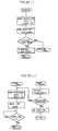
- the microcomputer 51 When operation of the automatic door 41 starts as shown in Fig. 10(a) from full shut position of the door42 as the initial position, the microcomputer 51 set on the open register 51 b a sufficiently large value, "2000" for example, and also set on the close register 51c the complement "-2000", i.e. a sufficiently small value.
- the visitor flag 60 and delay circuit 62 are reset by the output pulse n and the condition is kept waiting for setting of the visitor flag 60.
- the mat switch MS is pressed by a visitor and the mat signal M1 turns to "1"
- the visitor flag 60 is set.
- the output signals m and u are transmitted.
- the speed counter 53, the flags 57, 58, 59, the break counter 71 and the break flag 73 are reset.
- the output signal m is also given into the OR gate 64. But any effection will not occur at all since the mat signal "M1" is "1".
- the motor turning direction is in "Open direction”
- the speed is set to "V1”
- the brake is set to "OFF” at high-speed open mode.
- the door 42 starts open motion at V1 speed.
- the belt 43 is broken and the motor 44 is judged idling. Accordingly, the mode changes to break trouble mode.
- the brake is turned to on without changing condition of the motor 44 under open braking mode.
- the open braking mode completes on one of the three cases, low-speed open flag 57 turning to "1", break flag 73 turning to "1", or comparator 70 turning to "1".
- the brake is operated normally, accordingly the speed is lowered.
- the low-speed open flag 57 detects that the door speed reaches V2
- visitor or no visitor is checked by the visitor flag 60. If there is a visitor, the mode changes to low-speed open mode and if no visitor stays, it changes to reversing close braking mode as there is no need to continue open motion any longer.
- the 3rd case means that the speed of the door 42 is increased during the braking motion and this condition is judged that the brake is not operating normally. So it changes to brake trouble mode.
- the braking operation is controlled in the following manner.
- the microcomputer 51 provides the brake signal f3 at the specified duty ratio, reads the output value of the break counter 71 under that situation, then reads the output value of the break counter 71 again after a certain period, and compares the difference between the output values with the preset reference value.
- the duty ratio is increased if the said difference is larger than the reference value taking that the braking effect is smaller. If the difference is smaller than the reference value, on the other hand, the duty ratio is decreased judging that the braking effect is larger.
- the braking effect is automatically adjusted to an adequate level at all times even if the conditions are changing. Accordingly, smooth motion of the door 42 is ensured as desired.
- the motor 44 is so controlled that the brake is turned to "OFF" and the door 42 opens at V2 speed, as shown in Fig. 10(d).
- the stop flag 59 When this is detected by the stop flag 59, it changes to normal free mode. If the belt 43 is broken, however, the motor 44 keeps idling and the output of the break counter 71 increases, then the stop flag 59 does not turn to "1" but the break flag 74 turns to "1". At this time, the mode changes to break trouble.
- the motor 44 is stopped, the brake is turned to OFF and the door 42 is set free, as shown in Fig. 10(e).
- the output of the break counter 71 shows the number of the speed pulse signal Q1, which corresponds to the full stroke of the door 42 from full shut position to full open position.
- the value on the break counter 71 is given as the input and is compared with the previously memorized value into the open register 51 b. If the input value is smaller, a larger value by the specified difference than the input is set to the open register 51 b.
- the specified difference can be determined from the allowable slip length of the belt 43.
- the initial input is always smaller than the initially memorized value. Accordingly, the 1st comparison between the memorized value in the open register 51 and the input value into the break counter 71 is meaningless. But from the 2nd time and on, the comparison becomes meaningful.
- the previously memorized value in the open register 51 b is compared with the value of the break counter 71. If the belt 43 has already slipped by more than 9 mm at this time, the value of the break counter 71 is over "1003" and the mode changes to opening slip trouble mode.
- Slip trouble of the belt 43 can be detected in this manner through comparison of the value of the open register 51b with the value of the break counter 71.
- the value of the open register 51 b is renewed to a larger value by the specified difference than the input value into the break counter 71. While the visitor flag 60 is "1", as it means that a visitor stays on the mat switch MS, the door 42 is kept under free.
- the mode changes to close braking mode.
- the speed of the door 42 comes down below 10 mm/sec in the middle of high-speed closing mode. Transfer of the door 42 is bothered by some other object and the mode changes to trouble reversing mode.
- the belt 43 is broken and the motor 44 is judged idling. Accordingly, the mode changes to break trouble mode.
- Close braking mode is ended in one of the following three cases; when the low-speed closing flag 58 is turned to "1”, when the brake flag 73 is turned to "1", or when the comparator 70 is turned to "1".
- brake operation is normal and door speed is lowered by braking.
- door speed lowered to V4 is detected by the low-speed closing flag 58, any visitor or no visitor is checked by the visitor flag 60. If no visitor is there, the mode turns to low-speed closing mode. If any visitor stays, the mode changes to reversing open braking mode as it is necessary to open the door 42.
- the belt 43 is judged broken and the mode changes to break trouble mode.
- the 3rd case means that speed of the door 42 is increased during braking, and the brake operation is judged abnormal. Accordingly, the mode changes to brake trouble mode.
- the motor 44 is so controlled that the brake is turned to "OFF” and the door 42 is closed at V4 speed, as shown in Fig. 10(h).
- the motor turning direction is in "Open direction”
- the torque is "T”
- the brake is "OFF” as shown in Fig. 10(i). Accordingly, the motor drive control unit 46 generates faint torque T in door closing direction on the motor 44 by lowering the supply voltage to the motor 44.
- the door 42 Because of the torque T, the door 42 is pressed against the door stop with a force which can be opened by hands and tightly closed condition of the door 42 is maintained.
- the door 42 has reached to full shut position and the output of the break counter 71 indicates the number of the speed pulse signal Q1 corresponding to the full stroke of the door 42 from full open to full shut.
- the number is negative for count-down and expressed as a complement.
- the value of the break counter 71 is read, compared with the value previously memorized in the close register 51c, and the value smaller than the reading by a specific difference is set on the close register 51c if the reading value is smaller than the memorized value.
- the specific difference can be determined from the allowable slip length of the belt 43. If the allowable slip length is 9 mm, and output of speed pulse signal Q1 is given at every 3 mm transfer of the door 42, for example, the specific value is "3". If the reading on the break counter 71 is "-1000", therefore, "-1003" is set on the close register 51 c.
- Slip trouble of the belt 43 can be detected in this manner through comparison of the value of the close register 51c with the value of the break counter 71.
- the value of the close register 51c is renewed to a value smaller than the input value into the break counter 71 by the specific difference, and the mode changes to open stand-by mode as shown in Fig. 1 (a).
- Fig. 10(j) shows processing under trouble free - mode and trouble reverse mode.
- the trouble counter 51 a is subjected to increment. If the number of times of trouble is less than the specified number of times, three times for example, output of pulse m is given, and the mode changes to the middle open mode shown in Fig. 10(a). The door 42 is reversed by this to open operation.
- the door 42 Since the output pulse m is instantaneous, the door 42 is turned to close operation again after the delay the in the delay circuit 62. If the cause of trouble is not removed at this time, however, it turns to trouble reverse mode again and the same operation is repeated.
- the repetition When the repetition reaches the specified number of times, it changes to trouble free mode as further repetition of open-close operation is meaningless. In other words, the door 42 is kept in free condition after repeating trouble reversing by the specified number of times.
- the door 42 turns to open stand-by mode of Fig. 10(a) after the normal closing operation, and the trouble counter 51a a is reset to normal stand-by condition of the initial stage.
- Fig. 10(k) shows processing of the break trouble mode, in which the motor 44 is stopped immediately, and the brake is turned to "OFF". Then output of alarm signal a1 is given, the alarm 47 transmits alarm sound repeatedly and intermittently, and operation of the automatic door 41 is stopped under this condition.
- Fig. 10(1) shows processing of brake trouble mode, in which the motor 44 is stopped immediately, and the brake is turned to "OFF". Then output of alarm signal a1 is given, the alarm 47 transmits alarm sound repeatedly and intermittently, and operation of the automatic door 41 is stopped under this condition.
- Fig. 10(m) shows processing of opening slip trouble mode. Although, the alarm sound of specific pattern is transmitted for the specified time, mode turns to the close stand-by mode shown in Fig. 10(e) as there is no need to stop operation of the automatic door 41.
- Fig. 10(n) shows processing of closing slip trouble mode. Although, the alarm sound of another specific pattern is transmitted for the specified time, the mode turns to the open stand-by mode shown in Fig. 10(a) as there is no need to stop operation of the automatic door 41.
- this automatic door 41 detects break of the belt 43, stops operation, and transmits alarm. Slipping of the belt 43 is also detected at an early stage and alarm is transmitted. The operator can guess the cause of trouble easily since the alarm transmission is made in a specific pattern depending on each cause of trouble.
- alarm means lamp, buzzer, and CRT display may be used, for example.
- the alarm which can identify and notify brake defect is preferable, in particular.
- Other embodiments may include the arrangement to judge door position from speed pulse signal so as to eliminate door position sensors LS1, LS2, may include infrared ray type sensors-or radar type sensors in place of the mat switch MS, or may include the arrangement to comprise the central control unit 50 with hardware circuits without using the microcomputer 51.
Landscapes
- Power-Operated Mechanisms For Wings (AREA)
Claims (7)
Applications Claiming Priority (6)
| Application Number | Priority Date | Filing Date | Title |
|---|---|---|---|
| JP77432/84 | 1984-04-16 | ||
| JP59077432A JPH078159B2 (ja) | 1984-04-16 | 1984-04-16 | オ−トドアのブレ−キ制御装置 |
| JP59095768A JPS6036340A (ja) | 1983-05-16 | 1984-05-15 | ガラス板の保持枠 |
| JP95768/84U | 1984-06-25 | ||
| JP59183147A JPS6162375A (ja) | 1984-08-31 | 1984-08-31 | オートドアのブレーキ制御方法 |
| JP183147/84 | 1984-08-31 |
Publications (2)
| Publication Number | Publication Date |
|---|---|
| EP0162280A1 EP0162280A1 (fr) | 1985-11-27 |
| EP0162280B1 true EP0162280B1 (fr) | 1988-07-13 |
Family
ID=27302419
Family Applications (1)
| Application Number | Title | Priority Date | Filing Date |
|---|---|---|---|
| EP85104584A Expired EP0162280B1 (fr) | 1984-04-16 | 1985-04-16 | Mécanisme de frein pour une porte automatique |
Country Status (2)
| Country | Link |
|---|---|
| US (1) | US4698622A (fr) |
| EP (1) | EP0162280B1 (fr) |
Families Citing this family (16)
| Publication number | Priority date | Publication date | Assignee | Title |
|---|---|---|---|---|
| US4847541A (en) * | 1987-10-30 | 1989-07-11 | Steve Krieger | Door actuating system |
| DE3834643C2 (de) * | 1988-10-11 | 1995-11-30 | Berner Fa | Antriebseinheit |
| DE3913107A1 (de) * | 1989-04-21 | 1990-10-25 | Hans Gugu | Antrieb fuer mittels rollen verfahrbaren toren |
| US5170108A (en) * | 1991-01-31 | 1992-12-08 | Daylighting, Inc. | Motion control method and apparatus for motorized window blinds and and the like |
| DE9116356U1 (de) * | 1991-03-08 | 1992-07-30 | Siemens AG, 8000 München | Elektronische Automatik-Türsteuerung |
| JPH0893323A (ja) * | 1994-09-29 | 1996-04-09 | Oi Seisakusho Co Ltd | 開閉体の駆動制御装置 |
| US6091217A (en) * | 1998-01-29 | 2000-07-18 | Elite Access Systems, Inc. | Safety gate operator which prevents entrapment, and method of its operation |
| US6014307A (en) * | 1998-03-24 | 2000-01-11 | The Chamberlain Group, Inc. | Fire door operator having an integrated electronically controlled descent device |
| GB9818070D0 (en) * | 1998-08-20 | 1998-10-14 | Gunton Bruce S | Aperture closures |
| US6847178B2 (en) * | 2001-09-27 | 2005-01-25 | The Chamberlain Group, Inc. | Method and apparatus for dynamic braking of a barrier operator |
| DE102006034962B4 (de) * | 2006-07-28 | 2010-07-08 | Feig Electronic Gmbh | Verfahren zum gesicherten Bremsen eines Tores sowie Vorrichtung zur Durchführung des Verfahrens |
| JP5927794B2 (ja) * | 2011-07-19 | 2016-06-01 | アイシン精機株式会社 | 車両開閉体制御装置 |
| KR20160075544A (ko) | 2013-10-01 | 2016-06-29 | 워렌 인더스트리즈 엘티디. | 차량 도어 제어 시스템 |
| CN106014065A (zh) * | 2016-05-18 | 2016-10-12 | 吴自达 | 电动智控推拉门控制方法 |
| JP6530731B2 (ja) * | 2016-09-01 | 2019-06-12 | ファナック株式会社 | 数値制御装置 |
| CN116081262A (zh) * | 2023-01-19 | 2023-05-09 | 中国水利水电第八工程局有限公司 | 一种防止故障皮带机上持续进料的在前卸料方法 |
Family Cites Families (8)
| Publication number | Priority date | Publication date | Assignee | Title |
|---|---|---|---|---|
| DE2219477A1 (de) * | 1972-04-21 | 1973-11-08 | Spellmann Georg Hannover Holz | Verfahren zur steuerung eines schiebetuerenantriebs |
| JPS53115540A (en) * | 1977-03-19 | 1978-10-09 | Kazuyoshi Ozaki | Opening*closing end controlling apparatus for automatic door |
| US4203058A (en) * | 1978-08-25 | 1980-05-13 | General Motors Corporation | Failure detection circuit for dynamic braking system |
| US4429264A (en) * | 1980-03-03 | 1984-01-31 | Richmond Moscow K | System and method for the automatic control of electrically operated gates |
| JPS5721681A (en) * | 1980-07-15 | 1982-02-04 | Matsushita Electric Works Ltd | Automatic door |
| JPS5826178A (ja) * | 1981-08-11 | 1983-02-16 | 北陽電機株式会社 | 自動扉開閉装置 |
| JPS5854181A (ja) * | 1981-09-28 | 1983-03-31 | ワイケイケイ株式会社 | 自動開閉扉の制御装置 |
| US4563625A (en) * | 1984-05-17 | 1986-01-07 | The Stanley Works | Automatic door control system |
-
1985
- 1985-04-10 US US06/722,069 patent/US4698622A/en not_active Expired - Fee Related
- 1985-04-16 EP EP85104584A patent/EP0162280B1/fr not_active Expired
Also Published As
| Publication number | Publication date |
|---|---|
| EP0162280A1 (fr) | 1985-11-27 |
| US4698622A (en) | 1987-10-06 |
Similar Documents
| Publication | Publication Date | Title |
|---|---|---|
| US4698622A (en) | Brake apparatus for automatic door | |
| US4713591A (en) | Control and drive arrangement for movable members | |
| US4401929A (en) | Control apparatus of automatic door | |
| US4234833A (en) | Door operator system using counter circuit for determining limit positions | |
| JPH06225561A (ja) | パワーウインド装置のモータ制御方法 | |
| JPH06328942A (ja) | 車両ドアの制御方法 | |
| JPH06328941A (ja) | 車両ドア・コントローラ | |
| JPH11270226A (ja) | パワーウインド装置の挟み込み検知方法 | |
| JPH0776973A (ja) | 回動的据え付け部分の位置、回転方向そして回転速度、或はその何れかを検出する方法 | |
| GB2384575A (en) | System and method for automatically establishing control values for a control device | |
| KR980009087A (ko) | 엘리베이터 도어 제어장치 | |
| AU653192B2 (en) | Monitoring apparatus | |
| US5315220A (en) | Memory method of door opening and shutting stroke value in automatic door | |
| JP2954471B2 (ja) | 開閉体の開閉制御方法 | |
| JPH0665838B2 (ja) | 自動扉の電源投入時制御方法 | |
| KR900006059B1 (ko) | 자동도어의 브레이크 장치 | |
| JPH0559234B2 (fr) | ||
| JP2823554B2 (ja) | 窓ガラス開閉装置 | |
| JP2942120B2 (ja) | パワーウインドウ駆動制御装置 | |
| JPH0455178Y2 (fr) | ||
| JPH06463B2 (ja) | サンル−フ制御装置 | |
| JPS60219976A (ja) | オ−トドアのブレ−キ制御装置 | |
| SU1618451A1 (ru) | Устройство автоматического управлени электроприводом центрифуги | |
| JPH0327712B2 (fr) | ||
| JPS6356391B2 (fr) |
Legal Events
| Date | Code | Title | Description |
|---|---|---|---|
| PUAI | Public reference made under article 153(3) epc to a published international application that has entered the european phase |
Free format text: ORIGINAL CODE: 0009012 |
|
| 17P | Request for examination filed |
Effective date: 19850514 |
|
| AK | Designated contracting states |
Kind code of ref document: A1 Designated state(s): DE GB |
|
| 17Q | First examination report despatched |
Effective date: 19861222 |
|
| GRAA | (expected) grant |
Free format text: ORIGINAL CODE: 0009210 |
|
| AK | Designated contracting states |
Kind code of ref document: B1 Designated state(s): DE GB |
|
| REF | Corresponds to: |
Ref document number: 3563766 Country of ref document: DE Date of ref document: 19880818 |
|
| PLBE | No opposition filed within time limit |
Free format text: ORIGINAL CODE: 0009261 |
|
| STAA | Information on the status of an ep patent application or granted ep patent |
Free format text: STATUS: NO OPPOSITION FILED WITHIN TIME LIMIT |
|
| 26N | No opposition filed | ||
| PGFP | Annual fee paid to national office [announced via postgrant information from national office to epo] |
Ref country code: GB Payment date: 19960404 Year of fee payment: 12 |
|
| PGFP | Annual fee paid to national office [announced via postgrant information from national office to epo] |
Ref country code: DE Payment date: 19960529 Year of fee payment: 12 |
|
| PG25 | Lapsed in a contracting state [announced via postgrant information from national office to epo] |
Ref country code: GB Effective date: 19970416 |
|
| GBPC | Gb: european patent ceased through non-payment of renewal fee |
Effective date: 19970416 |
|
| PG25 | Lapsed in a contracting state [announced via postgrant information from national office to epo] |
Ref country code: DE Free format text: LAPSE BECAUSE OF NON-PAYMENT OF DUE FEES Effective date: 19980101 |