EP0163285B1 - Druckvorrichtung - Google Patents
Druckvorrichtung Download PDFInfo
- Publication number
- EP0163285B1 EP0163285B1 EP85106523A EP85106523A EP0163285B1 EP 0163285 B1 EP0163285 B1 EP 0163285B1 EP 85106523 A EP85106523 A EP 85106523A EP 85106523 A EP85106523 A EP 85106523A EP 0163285 B1 EP0163285 B1 EP 0163285B1
- Authority
- EP
- European Patent Office
- Prior art keywords
- ribbon
- printing
- carrier
- detecting
- color
- Prior art date
- Legal status (The legal status is an assumption and is not a legal conclusion. Google has not performed a legal analysis and makes no representation as to the accuracy of the status listed.)
- Expired
Links
Images






Classifications
-
- B—PERFORMING OPERATIONS; TRANSPORTING
- B41—PRINTING; LINING MACHINES; TYPEWRITERS; STAMPS
- B41L—APPARATUS OR DEVICES FOR MANIFOLDING, DUPLICATING OR PRINTING FOR OFFICE OR OTHER COMMERCIAL PURPOSES; ADDRESSING MACHINES OR LIKE SERIES-PRINTING MACHINES
- B41L1/00—Devices for performing operations in connection with manifolding by means of pressure-sensitive layers or intermediaries, e.g. carbons; Accessories for manifolding purposes
-
- B—PERFORMING OPERATIONS; TRANSPORTING
- B41—PRINTING; LINING MACHINES; TYPEWRITERS; STAMPS
- B41J—TYPEWRITERS; SELECTIVE PRINTING MECHANISMS, i.e. MECHANISMS PRINTING OTHERWISE THAN FROM A FORME; CORRECTION OF TYPOGRAPHICAL ERRORS
- B41J35/00—Other apparatus or arrangements associated with, or incorporated in, ink-ribbon mechanisms
- B41J35/36—Alarms, indicators, or feed disabling devices responsive to ink ribbon breakage or exhaustion
-
- B—PERFORMING OPERATIONS; TRANSPORTING
- B41—PRINTING; LINING MACHINES; TYPEWRITERS; STAMPS
- B41J—TYPEWRITERS; SELECTIVE PRINTING MECHANISMS, i.e. MECHANISMS PRINTING OTHERWISE THAN FROM A FORME; CORRECTION OF TYPOGRAPHICAL ERRORS
- B41J2/00—Typewriters or selective printing mechanisms characterised by the printing or marking process for which they are designed
- B41J2/315—Typewriters or selective printing mechanisms characterised by the printing or marking process for which they are designed characterised by selective application of heat to a heat sensitive printing or impression-transfer material
- B41J2/32—Typewriters or selective printing mechanisms characterised by the printing or marking process for which they are designed characterised by selective application of heat to a heat sensitive printing or impression-transfer material using thermal heads
- B41J2/325—Typewriters or selective printing mechanisms characterised by the printing or marking process for which they are designed characterised by selective application of heat to a heat sensitive printing or impression-transfer material using thermal heads by selective transfer of ink from ink carrier, e.g. from ink ribbon or sheet
-
- B—PERFORMING OPERATIONS; TRANSPORTING
- B41—PRINTING; LINING MACHINES; TYPEWRITERS; STAMPS
- B41J—TYPEWRITERS; SELECTIVE PRINTING MECHANISMS, i.e. MECHANISMS PRINTING OTHERWISE THAN FROM A FORME; CORRECTION OF TYPOGRAPHICAL ERRORS
- B41J35/00—Other apparatus or arrangements associated with, or incorporated in, ink-ribbon mechanisms
- B41J35/16—Multicolour arrangements
- B41J35/18—Colour change effected automatically
Definitions
- the present invention relates to a printing device according to the preamble of claim 1.
- This printing device being operable alternatively in a direct thermal printing mode, in a black ink printing mode or in a color ink printing mode.
- Printing devices are known (Japanese Patent Disclosure (Kokai) No. 58-63494, US-A-4 401 390, US-A-4 115 013). However, the said known printing devices do not operate always satisfactoryly in the three printing modes.
- a thermal printer using a thermal head can print directly on heat sensitive paper or can print using a thermal printing type black ink ribbon.
- the thermal printing and black ink printing mode are conventionally switched by a dip switch or the like.
- the printing mode can be selected from three modes including a color ink printing mode.
- the printing mode is switched by a dip switch as in a conventional printer, the operation becomes cumbersome and the printing mode may be erroneously set.
- the printing mode is ⁇ erroneously set when color ink ribbon is used, color adjusting processing such as color matching cannot be performed and the advantages of color printing may be lost.
- a detector is provided for detecting whether a ribbon cassette exists or not.
- the thermal printer is automatically changed in thermal sensitive process or thermal transfer process by installing or detaching the ribbon cassette. From this it results that this known printer can be used only in two different printing modes.
- a ribbon take-up motor is generally mounted on a carrier together with the ribbon cassette to wind the ribbon.
- this winding method requires a special purpose motor, which increases the cost.
- the motor is mounted on the carrier, the load of the carrier is increased and a large carrier driving motor must be used.
- a printing device comprising a platen for holding a paper sheet; a printing head pressed against the paper sheet on the platen in a black or color ink printing mode when the printing head is set in the ON-state; an ink ribbon being fed according to the movement of the printing head set in the ON-state; a carrier which holds the printing head and to which a black or color ink ribbon cassette is detachably mounted; a carrier driver for moving the carrier along the platen; a first detector for generating a color output signal when detecting that the color ink ribbon cassette is mounted on the carrier; a second detector, arranged in an ink ribbon path, for generating a first output signal while detecting a black area of the ink ribbon and for generating a second output signal while not detecting the black area; and a control unit which sets a color ink printing mode flag, when a power source voltage is applied to the printing device and, upon detecting that the first detector generates the color output signal, which sets the printing head in the
- the present invention it can be easily checked with reference to an output signal from the first detector whether or not the color ink ribbon is set.
- the printing head set in the ON-state is slightly moved, it can be easily checked in accordance with the output signal from the second detector whether or not the black ink ribbon is used or no ribbon is used.
- it can be easily and quickly checked if the printing mode is set in the direct printing mode, the black ink printing mode or the color ink printing mode.
- a mechanism of a thermal printer according to an embodiment of the present invention will be described with reference to Figs. 1 to 5.
- a drum- like platen 4 is held between side plates 2A and 2B projecting upward from the two ends of a frame 1.
- a rod-like guide shaft 5 and a guide plate 6 are fixed parallel to the platen 4.
- a carrier 7 is held by the shaft 5 and the plate 6.
- a belt 9 driven by a carrier motor 8 is looped between two pulleys 10A and 10B provided at the two ends of the frame 1. A portion of the belt 9 is fixed to the carrier 7.
- a thermal head 12 movable toward or away from the platen 4 by a solenoid 11 is fixed to the carrier 7, and a ribbon cassette 14 housing reels of an ink ribbon 13 is detachably mounted thereon.
- a ribbon end sensor 15 is provided on an upper surface of the carrier 7 so as to detect an end of the ribbon 13.
- a key assembly 18 including a print-on key 17 and a ribbon end lamp 19 are provided on an operation board 16 mounted on a front surface of the frame 1.
- a home position switch 20 is fixed to an end portion of the guide plate 6.
- the ribbon 13 is fed or wound in synchronism with movement of the carrier 7 set in the ON-state without using a special-purpose motor.
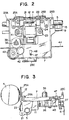
- the head 12 is arranged substantially at the center of that portion of the carrier 7 which opposes the platen 4.
- the head 12 is supported by a head holder 22 pivotally mounted on a supporting shaft 21 fixed to the carrier 7.
- the solenoid 11 is fixed to the carrier 7 through a solenoid fixing plate 23 behind the head 12.
- the head 12 is biased by a spring 24 provided between the plate 23 and the holder 22 in a direction away from the platen 4. Therefore, when the solenoid 11 is energized so as to push a rear surface of the holder 22, the head 12 is pressed against the platen 4.
- Paper guide plates 25A and 25B are fixed at two sides of the head 12. Furthermore, as shown in Fig. 3, a printed circuit (PC) board 26 connected to the head 12, the sensor 15 and the like is fixed on a lower surface of a rear portion of the carrier 7. A roll 27 is formed to roll along the plate 6.
- the carrier 7 has three engaging portions 28A, 28B and 28C. The portions 28A and 28B are positioned at two sides of the carrier 7 so as to oppose the printing surface and the portion 28C is formed at a rear end portion of the carrier 7 behind the head 12, so that lines connecting the portions 28A, 28B and 28C substantially form a regular triangle.
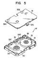
- the cassette 14 having holes 29C and 29D aligned with guide bosses 29A and 29B on the carrier 7 comprises a case 30 and a cover 31 to hold the ribbon 13 therein, as shown in Fig. 5.
- Elastic hooks 32A, 32B and 32C which elastically engage/ disengage with/from the portions 28A, 28B and 28C are formed on the cover 31 so as to correspond to the positions of the portions 28A, 28B and 28C.
- the case 30 is provided with a ribbon supply roll 33 and a take-up roll 34.
- the ribbon 13 is looped between the rolls 33 and 34 so as to pass through a receiving portion 35 which receives the head 12.
- a receiving portion 36 is formed to receive the sensor 15.
- a hole 37 is formed in the carrier 7 in a position corresponding to the position of the pulley 34, and a take-up shaft 38 for driving the pulley 34 extends through the hole 37.
- a take-up gear 39 is fixed to the shaft 38 at a lower surface side of the carrier 7.
- a lever 41, a gear 42 and a pulley 43 which are pivotal about a guide pin 40 are mounted next to the gear 39.
- the gear 42 and the pulley 43 are formed integrally and a portion of a wire 44 looped between the side plates 2A and 2B is wound around the pulley 43. Therefore, the pulley 43 and the gear 42 are rotated in synchronism with running of the carrier 7.
- a planetary gear 45 is rotatably mounted on the lever 41.
- the gear 45 is always meshed with the gear 42 and is positioned behind the gear 39 so that it may engage with or disengage from the gear 39.
- the distal end of the lever 41 extends to a position of the holder 22.
- a regulating portion 46 contacting or separating from the distal end of the lever 41 is formed on a portion of the holder 22.
- the portion 46 is brought into contact with the distal end of the lever 41 so as to prevent the lever 41 from being pivoted and to place the gear 45 in a position where it is not engaged with the gear 39.
- black and color ribbons can be selectively used as the ribbon 13.
- shapes of ribbon cassettes differ from each other for the black and color ribbons.
- a color ribbon detection switch 48 is provided on the PC board 26 so as to be turned on by an actuator 47 which is shifted downward only when the color ribbon cassette is set.
- the hooks 32A to 32C engage with the portions 28A to 28C, respectively.
- these engaging positions are at the left, right and rear sides of the head 12 and substantially form a regular triangle, the cassette 14 will not be influenced by vibration of the carrier 7, a pressing operation of the head 12, and the like. Therefore, the cassette 14 can be stably held on the carrier 7 without fluttering or floating therefrom. As a result, the ribbon 13 can be stably fed or wound, thus obtaining high printing quality. Since the cassette 14 can be mounted only by engaging the hooks 32A to 32C, it can be detached or mounted by pulling it up or pressing it toward the carrier 7.
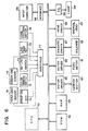
- Fig. 6 is a block diagram showing a control circuit of the thermal printer accordng to the embodiment of the present invention.
- the control circuit comprises a central processing unit (CPU) 50, a read-only memory (ROM) 52 storing a program to be executed by the CPU 50, and a random-access memory (RAM) 54 for temporarily storing control data transmitted from a host computer 56 via an interface 58 and printing control data obtained while executing the program.
- the CPU 50 is connected to a carrier motor 60, a feed motor 61, a solenoid 62, a thermal head 63 and a lamp 64 respectively through motor drivers 65 and 66, a solenoid driver 67, a head driver 68 and an I/O port 69.
- the motor 60, the solenoid 62, the head 63 and the lamp 64 respectively correspond to the motor 8, the solenoid 11, the head 12 and the lamp 19 shown in Figs. 1 and 2.
- the CPU 50 is connected to a print-on key 70, a color ribbon switch 71, an on-line switch 72, a line feed key 73, a home position switch 74, a paper end sensor 75 and a ribon end sensor 76 through an interface 77.
- the key 70, the switches 71 and 74 and the sensor 76 respectively correspond to the key 17, the switchs 48 and 20 and the sensor 15.
- data edit processing is executed in a main routine, and carrier driving control and printing control are executed in a time division manner in accordance with an interruption by a built-in timer.
- a carrier control routine is executed.
- a printing routine is then executed.
- a character pitch corresponds to 15 dots.
- the carrier 7 since a character pitch is 1/10 inch, the carrier 7 must be moved by 1/10 inch every time 15 dots are printed.
- a time required for printing one dot is 1,000 p sec
- Fig. 7 shows the relationship between a position of the carrier 7 and a printing timing.
- control of the dot number is basically executed using a dot counter (not shown) which is reset to "0" when the carrier 7 moves by a distance corresponding to 3 characters (9 steps) from the home position.
- a color ink ribbon will be described hereinafter.
- the ribbon can be wound by utilizing movement of the carrier 7 without using a special-purpose motor.
- a ribbon take-up amount becomes inevitably uneven. This is caused by a time delay or idling of the mechanisms because the ribbon take-up mechanism constituted by the gear 45, the pulley 43, the wire 44 and the like is operated after the head 12 presses the ribbon 13 against the platen 4. Since a sliding property of the ribbon depends upon a film material thereof, particular types of color pigments of the color ink ribbon, the ribbon take-up amount may become unstable. Such a variation in the ribbon take-up amount is not important in the case of a black ink ribbon because only a single color pigment is used.
- the color ink ribbon yellow, magenta, cyan segments each for one line are alternately arranged.
- the printing operation may be performed with a different color segment (i.e., color shift). That is, a total length of each color ribbon is determined by (about 8 inches of printing range) + (carrier slow-up range) + (carrier slow-down range). If the ribbon can be precisely wound, the color shift will not occur.
- the take-up amount is insufficient, a starting portion to be printed in the next color is printed in a color used in a preceding printing cycle.
- the ribbon is excessively wound, a last portion of the line is printed in a color of the next segment.
- a length of each color range of a color ink ribbon 13C is set as shown in Fig. 8. Note that before the carrier 7 starts moving, the head 12 is set in the ON-state so as to be pressed against the platen 4, and after the carrier 7 is stopped, the head 12 is set in the OFF-state so as to be separated from the platen 4. In a specific case, the head 12 can be set in the OFF-state while the carrier 7 moves. In any case, the ribbon take-up amount must be the same as the moving amount of the carrier 7 when the head 12 is in the ON-state. Yellow, magenta and cyan ribbon segments are used for the color ribbon.
- a black area marker is provided at a leading portion of each color segment.
- the markers are set to have two different lengths.
- a length dY of the marker at the leading portion of the yellow segment is set to be about 8 mm
- lengths dM and dC of the marks at the leading portions of the magenta and cyan segments are respectively set to be about 5 mm.
- the lengths dM and dC of about 5 mm are lower limits for permitting the marks to be correctly detected even if the lengths vary in a ribbon manufacturing process, and must be set to be as short as possible so as to prolong the color segment.
- the length dY is set to be about 8 mm because at least 3 mm is required for distinguishing the length dY from the lengths dM and dC.
- a length DY of a yellow segment DY is set to be 220.27 mm
- lengths DM and DC of magenta and cyan segments DM and DC are set to be 216.89 mm, respectively.
- the carrier 7 can move within the range between 213.36 mm. (i.e., the sum of (slow-up range), (printing range) and (slow-down range)) and 223.52 mm.
- 213.36 mm i.e., the sum of (slow-up range), (printing range) and (slow-down range)
- 223.52 mm 223.52 mm.
- a margin of about 3.25 mm is provided to compensate for the ribbon take-up shortage, and a margin of about 6.91 mm is provided to compensate for the excessive ribbon take-up.
- a margin of about 6.63 mm can be provided to compensate for the ribbon take-up shortage, and a margin of about 3.53 mm can be provided to compensate for the excessive ribbon take-up.
- margins in the yellow, cyan and magenta segments can be set to be the same.
- Figs. 9A and 9B show a moving amount of the carrier 7 for each color segment when the ink ribbon 13C is assumed to be correctly wound.
- the black ink ribbon also has the same ribbon end portion.
- the ON-time period of the head 12 is adjusted so as to finely adjust the ribbon take-up amount.
- the take-up amount is adjusted such that the carrier 7 is moved upon setting the head 12 in the ON-state independently of the printing operation.
- the printing operation is interruptted upon detecting the black area marker of the next color segment and it is determined that the printer is in the error state. Depression of the print-on key is then awaited.
- the error processing is executed so as to detect malfunction in the mechanism portion when the ribbon is excessively wound, since excessive winding of the ribbon is most frequently attributable to malfunction in the mechanism portion. Even when the ribbon is excessively wound, the error processing is not executed in the following case. That is, even when the black area marker of the next color segment is detected due to the excessive ribbon take-up during printing of one line, if the printing operation in the current color segment is completed, the error processing is not performed, the carrier 7 is stopped and the head 12 is separated away from the platen.
- a shortest access method is adopted.
- the shortest access method is not adopted and the carrier 7 is moved for a distance corresponding to one line for feeding the ribbon every printing cycle.
- Fig. 10 shows processing of a main routine.
- the RAM and the 1/0 ports are cleared so as to initialize the printer.
- 'the home position detection processing is performed. More specifically, the carrier 7 is moved to the left, and when the home position switch 20 detects the carrier 7, the carrier motor 8 is rotated by two steps so that the carrier 7 is moved to the right and is then stopped. Then, the paper end detection processing is performed as preprocessing so as to check if the paper end is detected. Thereafter, the mode determination processing is performed.
- the mode determination processing it is checked if the thermal printing mode using heat sensitive paper, the black ink printing mode using the black ink ribbon or the color ink printing mode using the color ink ribbon is set.
- This processing is shown in Figs. 11A and 11B.
- the color ribbon detection switch 48 is turned on. As described above, since the color and black ink ribbon cassettes have the diffferent shapes, only when the color ink ribbon cassette is set on the carrier 7, the actuator 47 is operated downward so as to turn on the switch 48. More specifically, a hole or notch is formed in a portion of the black ink ribbon cassette corresponding to the actuator 47 so as not to operate it.
- the switch 48 If the switch 48 is turned on, it is determined that the color ink ribbon is set, and the color ink printing mode flag is set in the RAM 54. On the other hand, if the switch 48 is turned off, it is determined that the black ink ribbon cassette is set or the heat sensitive paper is used. In order to perform this determination, the ribbon is slightly wound (e.g., 25 to 30 mm) when the power source voltage is supplied to the printer irrespective of the normal printing operation. Then, the solenoid 11 is energized, and the head 12 is set in the ON-state, thus pressing it against the platen 4. The motor 8 is driven stepwise to move-the carrier 7, thus winding the ribbon. In this case, information of the ribbon is read by utilizing the ribbon end sensor 15.
- the CPU 50 determines that the black ink ribbon is used. Thus, the black ink printing mode flag is set.
- the thermal printing mode flag is set.
- the motor 8 is driven by a predetermined number of steps, and it is checked if the carrier 7 is moved by 25 to 30 mm, i.e., if the mode determination operation is completed.
- the mode determination operation is basically performed by checking if the switch 48 is turned on, and if the sensor 15 detects the ribbon end.
- the switch 48 In the mode determination operation, even when the switch 48 is turned on, the ribbon is wound in the same manner as described above. This is performed for the ribbon end detection to be described later, and for preventing erroneous setting of the printing mode flag. In other words, when the switch 48 is turned on, it can be determined that the color ink printing mode is set. However, when the black ink ribbon is set, the switch 48 may be turned on for some reason: e.g., the black ink ribbon having the same shape as that of the color ink ribbon cassette is housed in the cassette. Therefore, even if it is determined the color ink printing mode is set, data of the ink ribbon is fetched by the sensor 15, and the CPU must determine in accordance with this data whether the color or black ink printing mode is set.
- the CPU 50 determines that the black ink ribbon is set (as shown in Fig. 8, the color ink ribbon does not have the black area, e.g., longer than 20 mm) and changes the printing mode. Then, the CPU resets the color ink printing mode flag and sets the black ink printing mode flag. When a transparent area is detected, a length thereof is stored in the RAM 54.
- the ribbon end is simultaneously determined.
- the ribbon end is present.
- the printing operation is interrupted, and the ribbon must be replaced.
- the ribbon end may be detected when the printer is powered. For this reason, the ribbon end determination is performed when the printer is powered.
- the information of the ink ribbon is read by the sensor 15.
- the sensor 15 comprises, e.g., a photocoupler. Since light cannot be transmitted through the black ribbon or the black area of the ribbon and can be transmitted through other color segments, the ribbon type can be detected.
- the black ribbon When the black ribbon is used, if a portion other than the black area is detected, it means that the stripe portion consisting of black and transparent areas at the ribbon end portion is detected. Thus, the CPU determines that the ribbon end is detected, and sets the ribbon end flag.
- the ribbon end determination is performed in accordance with the lengths of the detected transparent portions. In other words, in the stripe portion, since a length of the transparent portion is short, i.e., 2.54 mm, when the detected transparent portion has a length of 5 mm or less, it is determined that the ribbon end is detected, thus setting the ribbon end flag.
- the head 12 is set in the OFF-state, and the carrier 7 is set to the home position.
- the reason for using the switch 48 in the above-mentioned mode determination will be described.
- the color segments of the color ink ribbon 13C are transparent and the sensor 15 is operated as if no ink ribbon is provided. Therefore, in order to determine by a conventional method whether the color ink printing mode or the thermal printing mode is selected, the ribbon must be wound for a distance corresponding to one line (e.g., about 220 mm). This is because the black area between two adjacent color segments can be detected when the ribbon is wound for one line. However, this results in wasting the ribbon. In any mode, particularly, in the thermal printing mode, it is not preferable that the carrier 7 is moved a distance corresponding to one line every time the printer is powered. Therefore, the switch 48 is used to detect the color ink ribbon by slightly winding it.
- the paper end is detected.
- the head 12 in the ON-state, and the ribbon is wound by 25 to 30 mm.
- the head 12 is driven upon being pressed against the platen 4 directly or through the ink ribbon. Since the platen 4 of the thermal printer is soft and has a very low hardeness (about 25), a load of the carrier 7 is greatly increased as compared to the case wherein the paper 3 is present. For this reason, the motor 8 may cause malfunction.
- it is checked by the sensor 56 if the paper 3 is set. When the paper 3 is absent, running of the carrier 7 is inhibited. That is, the mode determination operation is not performed.
- Fig. 10A when the mode determination operation is completed and it is determined that the color ink printing mode is set, ribbon positioning is performed. Since color printing is performed in the order of yellow, magenta and cyan, the rountine for detecting the leading portion of the yellow segment is performed. Fig. 12 shows this routine. As shown in Fig. 8, this ribbon positioning is performed by utilizing that the black area marker of the yellow segment (about 8 mm) is longer than that of the magenta and cyan segments (about 5 mm). The head 12 is set in the ON-state, thus establishing the ribbon feed enable state. It is determined if the sensor 15 detects the black area.
- "B" flag is set so as to count the number thereof by the counter in the RAM 54, and the carrier 7 is moved to the right end. Thereafter, the head 12 is set in the OFF-state, and the carrier 7 is moved to the left so as to be set to the home position.
- the black marker is detected, i.e., every time the transparent area is detected immediately after the black area, the number of the black markers is counted and the "B" flag is reset.
- a length of the black marker is determined. If the black marker is about 8 mm in length, it is the one at the leading portion of the yellow segment, and the ribbon positioning is performed.
- the motor 8 is stopped, and the head 12 is set in the OFF-state. Thereafter, the carrier 7 is returned to the home position, thus enabling printing.
- the fourth black marker is detected and it does not have a length of about 8 mm, this may indicate a mechanical error, and the error flag is set. In this manner, the black area of the leading portion of the yellow segment is different from those of other segments, one set of color segments (yellow, magenta and cyan) can be easily detected, and the ribbon positioning can be easily performed.
- the processing up to the ribbon positioning routine corresponds to preset processing.
- the flow enters the main routine, and it is checked if the printer is set in a printing enable state. First, it is checked if the printer is in the on-line state (if in the off-line state, printing is disabled), and it is then checked if the paper end or ribbon end is detected. Thereafter, it is checked if data from the host computer is present, and if YES in this step, the flow enters in a data edition routine. Thus, the data sent from the host computer is analyzed and edited, and it is checked if the printing conditions are set up. If the printing conditions are satisfied, in the color ink printing mode, color adjustment is performed.
- a color to be currently printed is yellow, it is not necessary to change the ribbon position which has been set in the ribbon positioning process.
- the ribbon must be wound up to the leading portion of the magenta segment.
- a print setting routine a moving range of the carrier 7 is determined, the motor step number is calculated, printing data from the beginning of the printing up to the end is set, and a print start time is calculated. Thereafter, interrupt processing is executed so as to drive the carrier. Note that interrupt processing for driving the printer is executed during execution of interrupt processing for driving the carrier.
- the carrier 7 is driven in accordance with a slow-up routine, a constant speed routine, and a slow-down routine.
- the ribbon end is monitored, and when the ribbon end is detected, the carrier 7 is stopped and the head 12 is set in the OFF-state.
- ribbon control is also performed.
- the ribbon control is executed so as to prevent a color shift due to a variation in the ribbon take-up amount in the color ink printing mode.
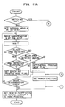
- the ribbon control will be explained with reference to Fig. 14.
- the printer is set in the thermal printing mode or black ink printing mode, the flow ends.
- a length of an area other than the black area i.e., the transparent area is calculated. If the length is 40 mm or less, the ribbon end flag indicating the stripe portion of the ribbon end is set. On the other hand, if the length of the transparent area is 40 mm or more, it is determined that the color ribbon is effectively set. Thereafter, when the black area marker is detected, the "B" flag is set.
- the CPU 50 checks if the carrier is in a fine adjustable range.
- the step number of the carrier 7 is increased or decreased, thus performing the fine adjustment.
- the fine adjustment processing shown in Fig. 15 is performed. More specifically, when the motor 8 is driven by the calculated number of steps upon setting the head 12 in the ON-state, the ribbon is further fed by the take-up shortage amount.
- the head 12 is set in the OFF-state, and the carrier 7 is returned to the home position. Then, the "B" flag is cleared.
- the processing is divided into two routines for insufficient and excessive take-up.
- the step number of the carrier motor corresponding to the take-up shortage amount is calculated and the additional take-up flag is set. As shown in Fig. 13, the additional take-up processing is executed in such a manner that the carrier 7 is moved by a desired amount after being returned to the home position. Therefore, this additional take-up processing differs from the take-up amount fine adjustment performed at the right end position.
- the ribbon when the ribbon is wound by 3.25 mm or more, the following two operations are performed.
- the black area marker of the leading portion of the color segment appears and the printing operation for the line in the current color segment is already completed, the head 12 is set in the OFF-state, the ribbon take-up operation is stopped, and this state is not regarded as an error.
- the ribbon end flag is set. This is because in the main processing and the off-line processing, the same processing is performed after the insufficient ribbon take-up occurs and after the ribbon end is detected.
- Fig. 16 shows a printing routine for printing by controlling an output of the head 12.
- the CPU 50 checks if the ribbon has not reached the ribbon end, and thereafter, sequentially reads out character data from the ROM 52 in accordance with input data received from the host computer 56 so as to supply them to the head 12.
- the printing routine ends.
- the ribbon end is always detected. Since the ink ribbon is of a one-time ribbon type, when the ribbon end is detected, the ink ribbon, i.e., the ribbon cassette must be replaced. Processing to be performed upon detecting the ribbon end during the printing operation will be explained hereinafter. The same processing can be applied to the black ink and the color ink printing modes.
- the printing operation is immediately stopped, and the carrier 7 is moved to the center and is then stopped. Thus, a new ribbon cassette 14 is set on the carrier 7. In this case, since the carrier 7 is stopped at the center, the replacement can be easily performed.
- the printing operation can be restarted from a position at which the printing operation was interrupted when the ribbon end was detected. More specifically, when the key 17 is depressed, the carrier 7 is returned from the center to the home position and is moved from the home position to the position at which the printing operation was interrupted. In respect of the printing dots, the printing dot position at which the printing operation is interrupted can be determined with reference to a dot counter "0" position separated from the home position by the number of dots corresponding to 3 characters. In the color ink printing mode, before the printing operation is resumed, the same color segment as that which is set when the printing operation is interrupted must be detected. As shown in Figs.
- the ribbon positioning is performed, and thereafter, the ribbon can be wound for selecting the same color segment as that which is set when the printing operation is interrupted before restarting the printing operation. Therefore, in the printing output, the printed data before and after the interruption cannot be distinguished from each other as if the ribbon replacement has not been performed during the printing operation, thus providing high printing quality. The printing quality can be further improved since the printing operation is not restarted from the beginning of the line by printing the printed data again.
Landscapes
- Impression-Transfer Materials And Handling Thereof (AREA)
- Electronic Switches (AREA)
- Accessory Devices And Overall Control Thereof (AREA)
Claims (5)
Applications Claiming Priority (2)
| Application Number | Priority Date | Filing Date | Title |
|---|---|---|---|
| JP59109228A JPH0661994B2 (ja) | 1984-05-29 | 1984-05-29 | サ−マルプリンタ |
| JP109228/84 | 1984-05-29 |
Publications (3)
| Publication Number | Publication Date |
|---|---|
| EP0163285A2 EP0163285A2 (de) | 1985-12-04 |
| EP0163285A3 EP0163285A3 (en) | 1986-02-19 |
| EP0163285B1 true EP0163285B1 (de) | 1989-11-08 |
Family
ID=14504855
Family Applications (1)
| Application Number | Title | Priority Date | Filing Date |
|---|---|---|---|
| EP85106523A Expired EP0163285B1 (de) | 1984-05-29 | 1985-05-28 | Druckvorrichtung |
Country Status (5)
| Country | Link |
|---|---|
| US (1) | US4652154A (de) |
| EP (1) | EP0163285B1 (de) |
| JP (1) | JPH0661994B2 (de) |
| KR (1) | KR850008648A (de) |
| DE (1) | DE3574116D1 (de) |
Families Citing this family (37)
| Publication number | Priority date | Publication date | Assignee | Title |
|---|---|---|---|---|
| US5156470A (en) * | 1983-10-13 | 1992-10-20 | Seiko Epson Corporation | Two cartridge ink-supply system for a multi-color dot matrix printer |
| US4669899A (en) * | 1984-12-26 | 1987-06-02 | Ricoh Company, Ltd. | Ink ribbon cartridge and color ink ribbon for printer |
| DE3602011A1 (de) * | 1985-01-26 | 1986-07-31 | Sharp K.K., Osaka | Thermotransfer-drucker |
| JPH07398B2 (ja) * | 1985-01-28 | 1995-01-11 | 沖電気工業株式会社 | プリンタ |
| US4779141A (en) * | 1986-01-28 | 1988-10-18 | Kabushiki Kaisha Toshiba | Image forming apparatus |
| US5051009A (en) * | 1986-07-15 | 1991-09-24 | Monarch Marking Systems, Inc. | Printhead mount & cassette lock in a thermal printer |
| JPH0729463B2 (ja) * | 1986-11-19 | 1995-04-05 | 日本電気株式会社 | インパクトプリンタ |
| JPS63134289A (ja) * | 1986-11-26 | 1988-06-06 | Canon Inc | 熱転写記録方法 |
| JPH0521410Y2 (de) * | 1986-12-02 | 1993-06-01 | ||
| JPH0639175B2 (ja) * | 1987-01-16 | 1994-05-25 | 沖電気工業株式会社 | 熱転写式記録装置 |
| US5017942A (en) * | 1987-02-27 | 1991-05-21 | Canon Kabushiki Kaisha | Ink ribbon cassette and recording apparatus which can be loaded with the ink ribbon cassette |
| US5445464A (en) * | 1987-02-27 | 1995-08-29 | Canon Kabushiki Kaisha | Ink ribbon usage in a multicolor image recording apparatus |
| JP2577901B2 (ja) * | 1987-02-27 | 1997-02-05 | キヤノン株式会社 | 記録装置 |
| US5009530A (en) * | 1987-10-31 | 1991-04-23 | Brother Kogyo Kabushiki Kaisha | Apparatus for reverse recording image and covering by protective medium |
| JPH01120371A (ja) * | 1987-11-05 | 1989-05-12 | Canon Inc | サーマルプリンタ |
| US4976558A (en) * | 1987-11-19 | 1990-12-11 | Brother Kogyo Kabushiki Kaisha | Device for feeding recording medium in the longitudinal recording direction |
| US5259680A (en) * | 1987-12-14 | 1993-11-09 | Hitachi, Ltd. | Thermal transfer printer and ink sheet cassette for use in same |
| US5193926A (en) * | 1987-12-21 | 1993-03-16 | Brother Kogyo Kabushiki Kaisha | Apparatus for recording image covered by protective medium |
| US5169247A (en) * | 1988-06-02 | 1992-12-08 | Canon Kabushiki Kaisha | Thermal printer with biaxial motor feed of the carriage and ribbon |
| US5096315A (en) * | 1989-02-02 | 1992-03-17 | Alps Electric Co., Ltd. | Ink ribbon winding mechanism |
| JPH02231183A (ja) * | 1989-03-03 | 1990-09-13 | Brother Ind Ltd | リボンカセットの揺動装置 |
| JPH02231184A (ja) * | 1989-03-06 | 1990-09-13 | Tokyo Electric Co Ltd | カラーインクリボンの色判別装置 |
| JPH02238984A (ja) * | 1989-03-10 | 1990-09-21 | Fujitsu Ltd | プリンタのインクリボンシフト機構 |
| DE4022696A1 (de) * | 1989-07-18 | 1991-01-31 | Canon Kk | Verfahren und vorrichtung zur ausbildung von aufzeichnungen mittels eines mehrfarben-farbbandes |
| US5127751A (en) * | 1989-11-30 | 1992-07-07 | Sharp Kabushiki Kaisha | Printing apparatus with improved work of ink ribbon replacement |
| US5098208A (en) * | 1990-01-12 | 1992-03-24 | Smith Corona Corporation | Ribbon cassette with integral paper guide |
| US5074689A (en) * | 1990-01-12 | 1991-12-24 | Smith Corona Corporation | Ribbon cassette with integral paper guide |
| US5089897A (en) * | 1990-02-08 | 1992-02-18 | Smith Corona Corporation | Facsimile paper supply cartridge system |
| US5057930A (en) * | 1990-02-08 | 1991-10-15 | Smith Corona Corporation | Plain paper cartridge for facsimile machine |
| US5060076A (en) * | 1990-02-08 | 1991-10-22 | Smith Corona Corporation | Thermal paper cartridge for facsimile machine |
| GB2243336A (en) * | 1990-04-24 | 1991-10-30 | Esselte Meto Int Gmbh | Portable printers. |
| EP0555888B2 (de) * | 1991-05-03 | 2000-07-05 | Brother Kogyo Kabushiki Kaisha | Auf Band druckendes Gerät |
| JPH05286219A (ja) * | 1992-04-13 | 1993-11-02 | Sony Corp | 色順次カラープリンタ装置 |
| US5691961A (en) * | 1993-03-30 | 1997-11-25 | Paranjpe; Suresh C. | Ribbon conservation in thermal printing |
| USD366059S (en) | 1994-11-14 | 1996-01-09 | Minnesota Mining And Manufacturing Company | Tape cartridge |
| US6132120A (en) * | 1995-03-29 | 2000-10-17 | Brother Kogyo Kabushiki Kaisha | Tape-shaped label printing device |
| GB202216641D0 (en) * | 2022-11-08 | 2022-12-21 | Dover Europe Sarl | Method, system and apparatus for detecting ribbon status in a printer |
Family Cites Families (25)
| Publication number | Priority date | Publication date | Assignee | Title |
|---|---|---|---|---|
| US3346090A (en) * | 1963-05-31 | 1967-10-10 | Ibm | Ribbon feed mechanism |
| US4019619A (en) * | 1976-03-22 | 1977-04-26 | Printronix, Inc. | Paper feed sensing mechanism for printer |
| US4115013A (en) * | 1977-03-30 | 1978-09-19 | Xerox Corporation | End-of-ribbon sensor device |
| DE2810768C3 (de) * | 1978-03-13 | 1981-03-19 | Olympia Werke Ag, 2940 Wilhelmshaven | Antriebsvorrichtung für das Farbband von Schreib-, Daten- oder ähnlichen Maschinen |
| US4401390A (en) * | 1979-04-18 | 1983-08-30 | Trilog, Inc. | Ribbon control system for multiple color impact printer |
| JPS55154193A (en) * | 1979-05-22 | 1980-12-01 | Tokyo Electric Co Ltd | Printer adopting multicolor ribbon |
| JPS5613193A (en) * | 1979-07-16 | 1981-02-09 | Ricoh Co Ltd | Ribbon feed amount change-over control system for printer |
| DE3003886A1 (de) * | 1980-02-02 | 1981-08-13 | Olympia Werke Ag, 2940 Wilhelmshaven | Farbbandkassette fuer eine schreib- o.ae. bueromaschine |
| JPS6017717B2 (ja) * | 1980-03-17 | 1985-05-04 | キヤノン株式会社 | 印字装置 |
| JPS578186A (en) * | 1980-06-17 | 1982-01-16 | Toshiba Corp | Apparatus for selecting type color of multicolor ink ribbon |
| JPS576786A (en) * | 1980-06-17 | 1982-01-13 | Toshiba Corp | Multicolor ink ribbon |
| JPS5751480A (en) * | 1980-09-16 | 1982-03-26 | Hitachi Ltd | Ink ribbon cassette |
| JPS57173192A (en) * | 1981-04-17 | 1982-10-25 | Hitachi Ltd | Impact system multicolor line printer |
| JPS57201686A (en) * | 1981-06-05 | 1982-12-10 | Sony Corp | Color printer |
| JPS5863494A (ja) * | 1981-10-14 | 1983-04-15 | Canon Inc | 印字装置 |
| JPS5894483A (ja) * | 1981-12-02 | 1983-06-04 | Seiko Instr & Electronics Ltd | カラ−転写装置及びリボン |
| JPS58148779A (ja) * | 1982-03-02 | 1983-09-03 | Sony Corp | 熱転写印刷方法 |
| JPS58155246U (ja) * | 1982-04-12 | 1983-10-17 | ブラザー工業株式会社 | 熱転写プリンタ |
| JPS58179680A (ja) * | 1982-04-14 | 1983-10-20 | Ricoh Co Ltd | プリンタ |
| US4506273A (en) * | 1982-06-02 | 1985-03-19 | Kabushiki Kaisha Daini Seikosha | Multicolor thermal transfer recorder with color detection means |
| JPS5939590A (ja) * | 1982-08-30 | 1984-03-03 | Shinko Electric Co Ltd | サ−マルカラ−プリンタ用カラ−転写フイルムの切れ検出方法 |
| JPS5971889A (ja) * | 1982-10-18 | 1984-04-23 | Tokyo Electric Co Ltd | サ−マルプリンタ |
| JPS59120488A (ja) * | 1982-12-28 | 1984-07-12 | Canon Inc | サ−マルプリンタ |
| JPS59123683A (ja) * | 1982-12-28 | 1984-07-17 | Brother Ind Ltd | サ−マルプリンタ |
| US4530612A (en) * | 1983-08-05 | 1985-07-23 | International Business Machines Corp. | Method for adaptively using a print ribbon in an impact printer |
-
1984
- 1984-05-29 JP JP59109228A patent/JPH0661994B2/ja not_active Expired - Lifetime
-
1985
- 1985-05-22 US US06/736,713 patent/US4652154A/en not_active Expired - Fee Related
- 1985-05-22 KR KR1019850003497A patent/KR850008648A/ko not_active Ceased
- 1985-05-28 DE DE8585106523T patent/DE3574116D1/de not_active Expired
- 1985-05-28 EP EP85106523A patent/EP0163285B1/de not_active Expired
Also Published As
| Publication number | Publication date |
|---|---|
| KR850008648A (ko) | 1985-12-21 |
| DE3574116D1 (en) | 1989-12-14 |
| EP0163285A3 (en) | 1986-02-19 |
| JPS60250981A (ja) | 1985-12-11 |
| EP0163285A2 (de) | 1985-12-04 |
| US4652154A (en) | 1987-03-24 |
| JPH0661994B2 (ja) | 1994-08-17 |
Similar Documents
| Publication | Publication Date | Title |
|---|---|---|
| US4652154A (en) | Thermal printer operative in three modes including direct printing, printing with black ink ribbon cassette, and printing with color ink ribbon cassette | |
| US6334724B2 (en) | Tape-shaped label printing device | |
| US5156464A (en) | Printer having gap adjusting apparatus for print head | |
| EP1311910A1 (de) | Bedarfsgesteuerte endlosmedium-elektrofotografiedruckvorrichtung | |
| KR20010080708A (ko) | 칼라 열 프린트 리본용 식별 코드 | |
| US4897670A (en) | Thermal transfer printer | |
| US4620199A (en) | Thermal transfer color printer | |
| US5669720A (en) | Thermal printer with minimized power difference between sequentially driven blocks of printing elements | |
| US4707159A (en) | Serial printer including a laterally reciprocable recording head, paper bail control, paper detection and feeding means, a multicolor ink ribbon including a head cleaning zone, a ribbon cassette and ribbon shift means | |
| JPH06191081A (ja) | 熱転写プリンタおよびリボンカセット | |
| JPH01195088A (ja) | 熱写転プリンタ | |
| US5519428A (en) | Thermal image-recording apparatus with sensor means for sensing the type of print sheet | |
| US5466074A (en) | Recording apparatus with mechanism for shifting ink ribbon cassettes | |
| US5631688A (en) | Thermal transfer printer | |
| US6095700A (en) | Battery operated thermal printer with means to optimize battery life | |
| KR940010361B1 (ko) | 자동용지 공급(loading) 기능을 갖는 인쇄장치 | |
| US5304008A (en) | Ink ribbon cassette with a frictioning member for imparting variable tension to an ink ribbon | |
| US6092946A (en) | Tape printing apparatus and tape holding case with a sliding switch | |
| JP2924837B2 (ja) | ラベルプリンタ | |
| JPS6154975A (ja) | プリンタ | |
| JPS6213377A (ja) | カラ−サ−マルプリンタのインクリボン頭出し方法 | |
| JPH0651411B2 (ja) | プリンタ装置 | |
| JPH06191131A (ja) | インクリボン | |
| EP0392425B1 (de) | Gerät und Verfahren zur Bildaufzeichnung | |
| JPS6038191A (ja) | サ−マルリボン送り機構 |
Legal Events
| Date | Code | Title | Description |
|---|---|---|---|
| PUAI | Public reference made under article 153(3) epc to a published international application that has entered the european phase |
Free format text: ORIGINAL CODE: 0009012 |
|
| AK | Designated contracting states |
Designated state(s): DE FR GB |
|
| PUAL | Search report despatched |
Free format text: ORIGINAL CODE: 0009013 |
|
| AK | Designated contracting states |
Designated state(s): DE FR GB |
|
| 17P | Request for examination filed |
Effective date: 19860724 |
|
| 17Q | First examination report despatched |
Effective date: 19871020 |
|
| GRAA | (expected) grant |
Free format text: ORIGINAL CODE: 0009210 |
|
| AK | Designated contracting states |
Kind code of ref document: B1 Designated state(s): DE FR GB |
|
| REF | Corresponds to: |
Ref document number: 3574116 Country of ref document: DE Date of ref document: 19891214 |
|
| ET | Fr: translation filed | ||
| PLBE | No opposition filed within time limit |
Free format text: ORIGINAL CODE: 0009261 |
|
| STAA | Information on the status of an ep patent application or granted ep patent |
Free format text: STATUS: NO OPPOSITION FILED WITHIN TIME LIMIT |
|
| 26N | No opposition filed | ||
| PGFP | Annual fee paid to national office [announced via postgrant information from national office to epo] |
Ref country code: FR Payment date: 19920417 Year of fee payment: 8 |
|
| PGFP | Annual fee paid to national office [announced via postgrant information from national office to epo] |
Ref country code: GB Payment date: 19920505 Year of fee payment: 8 |
|
| PGFP | Annual fee paid to national office [announced via postgrant information from national office to epo] |
Ref country code: DE Payment date: 19920729 Year of fee payment: 8 |
|
| PG25 | Lapsed in a contracting state [announced via postgrant information from national office to epo] |
Ref country code: GB Effective date: 19930528 |
|
| GBPC | Gb: european patent ceased through non-payment of renewal fee |
Effective date: 19930528 |
|
| PG25 | Lapsed in a contracting state [announced via postgrant information from national office to epo] |
Ref country code: FR Effective date: 19940131 |
|
| PG25 | Lapsed in a contracting state [announced via postgrant information from national office to epo] |
Ref country code: DE Effective date: 19940201 |
|
| REG | Reference to a national code |
Ref country code: FR Ref legal event code: ST |