EP0189115B1 - Dispositif à commande numérique - Google Patents
Dispositif à commande numérique Download PDFInfo
- Publication number
- EP0189115B1 EP0189115B1 EP86100488A EP86100488A EP0189115B1 EP 0189115 B1 EP0189115 B1 EP 0189115B1 EP 86100488 A EP86100488 A EP 86100488A EP 86100488 A EP86100488 A EP 86100488A EP 0189115 B1 EP0189115 B1 EP 0189115B1
- Authority
- EP
- European Patent Office
- Prior art keywords
- program
- ram
- power switch
- cpu
- storage device
- Prior art date
- Legal status (The legal status is an assumption and is not a legal conclusion. Google has not performed a legal analysis and makes no representation as to the accuracy of the status listed.)
- Expired - Lifetime
Links
Images
Classifications
-
- G—PHYSICS
- G05—CONTROLLING; REGULATING
- G05B—CONTROL OR REGULATING SYSTEMS IN GENERAL; FUNCTIONAL ELEMENTS OF SUCH SYSTEMS; MONITORING OR TESTING ARRANGEMENTS FOR SUCH SYSTEMS OR ELEMENTS
- G05B19/00—Program-control systems
- G05B19/02—Program-control systems electric
- G05B19/18—Numerical control [NC], i.e. automatically operating machines, in particular machine tools, e.g. in a manufacturing environment, so as to execute positioning, movement or co-ordinated operations by means of program data in numerical form
- G05B19/408—Numerical control [NC], i.e. automatically operating machines, in particular machine tools, e.g. in a manufacturing environment, so as to execute positioning, movement or co-ordinated operations by means of program data in numerical form characterised by data handling or data format, e.g. reading, buffering or conversion of data
-
- G—PHYSICS
- G05—CONTROLLING; REGULATING
- G05B—CONTROL OR REGULATING SYSTEMS IN GENERAL; FUNCTIONAL ELEMENTS OF SUCH SYSTEMS; MONITORING OR TESTING ARRANGEMENTS FOR SUCH SYSTEMS OR ELEMENTS
- G05B2219/00—Program-control systems
- G05B2219/30—Nc systems
- G05B2219/33—Director till display
- G05B2219/33125—System configuration, reconfiguration, customization, automatic
-
- G—PHYSICS
- G05—CONTROLLING; REGULATING
- G05B—CONTROL OR REGULATING SYSTEMS IN GENERAL; FUNCTIONAL ELEMENTS OF SUCH SYSTEMS; MONITORING OR TESTING ARRANGEMENTS FOR SUCH SYSTEMS OR ELEMENTS
- G05B2219/00—Program-control systems
- G05B2219/30—Nc systems
- G05B2219/36—Nc in input of data, input key till input tape
- G05B2219/36112—Floppy disk, diskette
-
- G—PHYSICS
- G05—CONTROLLING; REGULATING
- G05B—CONTROL OR REGULATING SYSTEMS IN GENERAL; FUNCTIONAL ELEMENTS OF SUCH SYSTEMS; MONITORING OR TESTING ARRANGEMENTS FOR SUCH SYSTEMS OR ELEMENTS
- G05B2219/00—Program-control systems
- G05B2219/30—Nc systems
- G05B2219/36—Nc in input of data, input key till input tape
- G05B2219/36395—Load local computer program from host, data transfer ram to rom, BTR
-
- Y—GENERAL TAGGING OF NEW TECHNOLOGICAL DEVELOPMENTS; GENERAL TAGGING OF CROSS-SECTIONAL TECHNOLOGIES SPANNING OVER SEVERAL SECTIONS OF THE IPC; TECHNICAL SUBJECTS COVERED BY FORMER USPC CROSS-REFERENCE ART COLLECTIONS [XRACs] AND DIGESTS
- Y02—TECHNOLOGIES OR APPLICATIONS FOR MITIGATION OR ADAPTATION AGAINST CLIMATE CHANGE
- Y02P—CLIMATE CHANGE MITIGATION TECHNOLOGIES IN THE PRODUCTION OR PROCESSING OF GOODS
- Y02P90/00—Enabling technologies with a potential contribution to greenhouse gas [GHG] emissions mitigation
- Y02P90/02—Total factory control, e.g. smart factories, flexible manufacturing systems [FMS] or integrated manufacturing systems [IMS]
Definitions
- the present invention relates to a numerical control device in an automatic programmed or numerically controlled machine tool.
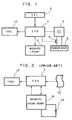
- a conventional numerical control device hereinafter referred to as an "NC device", is shown in Fig. 3, wherein a CPU 1 is connected with a memory 2, which includes a random access memory (RAM) and read only memory (ROM), and a tape reader 15.
- the memory 2 has a battery 16 which supplies the same, when a main power is turned off, with necessary power for retaining contents of data stored in the RAM.
- a tool 17 which performs desired machining work is controlled by a numerical control signal coming from the CPU.
- the operation of the numerical control for performing the desired machining work is of the tool begun with reading of the relevant working program data recorded in a paper tape by the tape reader 15.
- the data thus read out is written, as a first step, into the RAM of the memory 2 under the control of the CPU.
- the CPU reads, according to a control program stored in the ROM of the memory 2 in advance, the data written in the RAM piece by piece to supply the same to the tool 17 for the desired machining work.
- the data once written in the RAM is retained, even after the main power switch of the device has been turned off, by means of the power of the backup battery 16.
- the present invention is directed to the provision of an approach to solve the above two important problems encountered in the prior art NC device.
- the NC device of the present invention comprises a CPU, an initial program loader having an exchangeable storage medium which stores a predetermined starting program and connected with the CPU, a RAM connected with the CPU, a non-volatile storage device which stores a predetermined control program and working program and is connected with the CPU, and a power unit connected with the storage device through a power switch, wherein the initial program loader is provided, in response to closing of a main power switch of the NC device and in accordance with the starting program, for (a) turning on the power switch to render the storage device operable; (b) reading the control program and the working program stored in the storage device and writing the same into the RAM at a predetermined address; (c) in succession to completion of the write operation of the program into the RAM, turning the power switch off to render the storage device inoperable; and (d) causing the control program stored in the RAM to be started.
- An appropriate storage device for use in the invention is a floppy disk device.
- the floppy disk device is required to operate only while the control program and working program are being transferred to the RAM and it is cut off from the power unit in other period of time than that.
- a CPU 1 is connected with a RAM 2, an initial program loader 3, a storage device 4 having an easily exchangeable and nonvolatile memory such as a floppy disk, and a tool 17.
- the initial program loader hereinafter referred to as an "IPL"
- IPL is provided, in response to a closing operation of a main power switch (not shown) of the NC device, to control operations of the CPU in accordance with a predetermined starting program, of which detailed description will be given later.
- the storage device 4 is connected through a power switch 6 to a power unit 5.
- a control program and a working program stored in the nonvolatile memory are read out under the control of the CPU and then written into the RAM 2.
- an example of the appropriate nonvolatile memory is a floppy disk, it may be constituted of any other nonvolatile memory elements such as a bubble memory, a hard disk, and so on.
- the power switch 6 is turned off by a command from the CPU and the control program is started. The operation up to this point are specified by the starting program stored in the IPL 3.
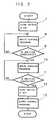
- FIG. 2 A flow chart of the processing operations performed according to the starting program is shown in Fig. 2.
- the start is effected by the closing of the main power switch of the NC device.
- the first processing step is the step 7 to turn on the power switch 6 provided between the storage device 4 and the power unit 5.
- the storage device 4 is rendered operable, the control program is first read from the nonvolatile memory of, for example, a floppy disk by a command from the CPU to the storage device 4 in accordance with the starting program, and this control program is written, through the CPU, into the RAM 2 at a predetermined address (step 8).
- the working program data is read out from the storage device 4 and written in the RAM 2 at a predetermined address in the step 10 in the same manner as in the case of the control program. Completion of the write operation of the control program into the RAM is confirmed in the step 11. After the completion of the write operation of the working program, the power switch 6 is turned off (step 12), and in succession thereto the control program transferred to the RAM 2 is made to start in the step 13.
- Steps 8 and 10 are interchangeable to each other.
- step 7 may be followed by steps 10 and 11, and then steps 8 and 9 may be executed.
- the working data is written in the RAM 2, in advance to the writing of the control program in the RAM 2.
- extension and modification of the system can be readily achieved by exchanging the storage medium in the IPL 3 storing the starting program of a pattern for that storing another pattern.
Landscapes
- Engineering & Computer Science (AREA)
- Human Computer Interaction (AREA)
- Manufacturing & Machinery (AREA)
- Physics & Mathematics (AREA)
- General Physics & Mathematics (AREA)
- Automation & Control Theory (AREA)
- Numerical Control (AREA)
Claims (1)
- Dispositif à commande numérique pour une machine outil numériquement commandée comprenant :
une unité centrale (1) ;
un chargeur de programme initial (3) comportant un support de mémoire échangeable qui mémorise un programme de lancement prédéterminé et qui est relie à ladite unité centrale (1) ;
une mémoire vive (2) reliée à ladite unité centrale (1) ;
un dispositif de mémoire rémanente (4) tel qu'une unité de disque souple, une unité de disque dur ou analogues qui mémorise un programme de commande et un programme d'usinage prédéterminés et qui est reliée à ladite unité centrale (1) ;
et une alimentation (5) reliée audit dispositif de mémoire (4) par l'intermédiaire d'un interrupteur d'alimentation (6) ;
dans lequel ledit chargeur de programme initial (3) est prévu, en réponse à la fermeture de l'interrupteur d'alimentation secteur dudit dispositif à commande numérique et en conformité avec le programme de lancement pour(a) fermer l'interrupteur d'alimentation (6) afin de rendre ledit dispositif de mémoire (4) opérationnel;(b) lire le programme de commande et le programme d'usinage mémorisés dans ledit dispositif de mémoire (4) et les écrire dans ladite mémoire vive (2) à une adresse prédéterminée ;(c) ensuite, à l'achèvement de l'opération d'écriture des programmes dans ladite mémoire vive (2), ouvrir l'interrupteur d'alimentation (6) pour rendre ledit dispositif de mémoire (4) non opérationnel ; et(d) amener le programme de commande mémorisé dans la mémoire vive (2) à être lancé.
Applications Claiming Priority (2)
| Application Number | Priority Date | Filing Date | Title |
|---|---|---|---|
| JP7384/85 | 1985-01-21 | ||
| JP60007384A JPS61184607A (ja) | 1985-01-21 | 1985-01-21 | 数値制御装置 |
Publications (3)
| Publication Number | Publication Date |
|---|---|
| EP0189115A2 EP0189115A2 (fr) | 1986-07-30 |
| EP0189115A3 EP0189115A3 (en) | 1988-08-10 |
| EP0189115B1 true EP0189115B1 (fr) | 1991-11-06 |
Family
ID=11664437
Family Applications (1)
| Application Number | Title | Priority Date | Filing Date |
|---|---|---|---|
| EP86100488A Expired - Lifetime EP0189115B1 (fr) | 1985-01-21 | 1986-01-16 | Dispositif à commande numérique |
Country Status (3)
| Country | Link |
|---|---|
| EP (1) | EP0189115B1 (fr) |
| JP (1) | JPS61184607A (fr) |
| DE (1) | DE3682293D1 (fr) |
Family Cites Families (4)
| Publication number | Priority date | Publication date | Assignee | Title |
|---|---|---|---|---|
| DE2319507A1 (de) * | 1972-04-26 | 1973-11-15 | Bendix Corp | Verfahren und vorrichtung zur eingabe eines steuerprogramms in einen rechner fuer die numerische steuerung einer werkzeugmaschine |
| JPS5760409A (en) * | 1980-09-30 | 1982-04-12 | Fanuc Ltd | Loading system of numerical control device |
| US4423484A (en) * | 1981-03-30 | 1983-12-27 | Hamilton William H | Irrigation control system |
| JPS60237892A (ja) * | 1984-05-09 | 1985-11-26 | Toshiba Corp | ステツピングモ−タ制御回路 |
-
1985
- 1985-01-21 JP JP60007384A patent/JPS61184607A/ja active Pending
-
1986
- 1986-01-16 EP EP86100488A patent/EP0189115B1/fr not_active Expired - Lifetime
- 1986-01-16 DE DE8686100488T patent/DE3682293D1/de not_active Expired - Lifetime
Also Published As
| Publication number | Publication date |
|---|---|
| EP0189115A3 (en) | 1988-08-10 |
| JPS61184607A (ja) | 1986-08-18 |
| DE3682293D1 (de) | 1991-12-12 |
| EP0189115A2 (fr) | 1986-07-30 |
Similar Documents
| Publication | Publication Date | Title |
|---|---|---|
| JPS6244281B2 (fr) | ||
| JPS5856192B2 (ja) | バブルメモリにおけるデ−タ書き替え方式 | |
| US6625712B2 (en) | Memory management table producing method and memory device | |
| US5274562A (en) | Numerical control unit for facilitating tool change | |
| US4396973A (en) | Programmable sequence controller | |
| US4794541A (en) | Numerical control method | |
| KR910007258B1 (ko) | Nc데이터 작성방법 | |
| EP0189115A2 (fr) | Dispositif à commande numérique | |
| US4086633A (en) | Numerical control system with program access function | |
| JPH0325293B2 (fr) | ||
| KR880000231B1 (ko) | 기억 영역 재편성 방식 | |
| EP0382853B1 (fr) | Unite de commande programmable | |
| EP0328663A4 (en) | Method of replacing the tools | |
| JPS60181804A (ja) | 数値制御工作機械 | |
| US4825382A (en) | Numerical control program editing and storage in RAM and ROM | |
| JPH10240633A (ja) | メモリシステム及びメモリカード | |
| JPS5929376B2 (ja) | 工具コ−ドの指定方法 | |
| JPH04304943A (ja) | 工具マガジンにおける工具情報読み書き装置 | |
| JPH01146638A (ja) | 工作機械の制御方法及び装置 | |
| JP2522040B2 (ja) | 位置決め機能付きプログラムコントロ―ラのプログラム入力方法 | |
| JPS6319007A (ja) | 数値制御装置におけるデ−タ伝送方法 | |
| JPS6348698A (ja) | メモリ格納制御装置 | |
| KR830002110B1 (ko) | 수치제어 공작 기계의 시이퀀스 제어방식 | |
| KR850002417Y1 (ko) | 불 휘발성 메모리의 데이터 재기록 시스템 | |
| JPH03288208A (ja) | 数値制御装置 |
Legal Events
| Date | Code | Title | Description |
|---|---|---|---|
| PUAI | Public reference made under article 153(3) epc to a published international application that has entered the european phase |
Free format text: ORIGINAL CODE: 0009012 |
|
| AK | Designated contracting states |
Kind code of ref document: A2 Designated state(s): DE FR GB |
|
| PUAL | Search report despatched |
Free format text: ORIGINAL CODE: 0009013 |
|
| AK | Designated contracting states |
Kind code of ref document: A3 Designated state(s): DE FR GB |
|
| 17P | Request for examination filed |
Effective date: 19890125 |
|
| 17Q | First examination report despatched |
Effective date: 19900913 |
|
| GRAA | (expected) grant |
Free format text: ORIGINAL CODE: 0009210 |
|
| AK | Designated contracting states |
Kind code of ref document: B1 Designated state(s): DE FR GB |
|
| REF | Corresponds to: |
Ref document number: 3682293 Country of ref document: DE Date of ref document: 19911212 |
|
| ET | Fr: translation filed | ||
| PLBI | Opposition filed |
Free format text: ORIGINAL CODE: 0009260 |
|
| 26 | Opposition filed |
Opponent name: PHILIPS ELECTRONICS N.V. Effective date: 19920724 |
|
| PGFP | Annual fee paid to national office [announced via postgrant information from national office to epo] |
Ref country code: FR Payment date: 19930111 Year of fee payment: 8 |
|
| PGFP | Annual fee paid to national office [announced via postgrant information from national office to epo] |
Ref country code: GB Payment date: 19930112 Year of fee payment: 8 |
|
| PLAB | Opposition data, opponent's data or that of the opponent's representative modified |
Free format text: ORIGINAL CODE: 0009299OPPO |
|
| PLAB | Opposition data, opponent's data or that of the opponent's representative modified |
Free format text: ORIGINAL CODE: 0009299OPPO |
|
| PLAB | Opposition data, opponent's data or that of the opponent's representative modified |
Free format text: ORIGINAL CODE: 0009299OPPO |
|
| R26 | Opposition filed (corrected) |
Opponent name: GRUNDIG AG Effective date: 19920724 |
|
| R26 | Opposition filed (corrected) |
Opponent name: PHILIPS ELECTRONICS N.V. Effective date: 19920724 |
|
| R26 | Opposition filed (corrected) |
Opponent name: GRUNDIG AG Effective date: 19920724 |
|
| PGFP | Annual fee paid to national office [announced via postgrant information from national office to epo] |
Ref country code: DE Payment date: 19940110 Year of fee payment: 9 |
|
| PG25 | Lapsed in a contracting state [announced via postgrant information from national office to epo] |
Ref country code: GB Effective date: 19940116 |
|
| RDAC | Information related to revocation of patent modified |
Free format text: ORIGINAL CODE: 0009299REVO |
|
| RDAG | Patent revoked |
Free format text: ORIGINAL CODE: 0009271 |
|
| STAA | Information on the status of an ep patent application or granted ep patent |
Free format text: STATUS: PATENT REVOKED |
|
| GBPC | Gb: european patent ceased through non-payment of renewal fee |
Effective date: 19940116 |
|
| 27W | Patent revoked |
Effective date: 19940314 |
|
| R27W | Patent revoked (corrected) |
Effective date: 19940314 |