EP0222668B1 - Verfahren zum Herstellen eines Dünnschichttransistors mit in Bezug auf Source und Drain selbstausrichtendem Gate durch stufenweises Ätzen und danach hergestellter Transistor - Google Patents
Verfahren zum Herstellen eines Dünnschichttransistors mit in Bezug auf Source und Drain selbstausrichtendem Gate durch stufenweises Ätzen und danach hergestellter Transistor Download PDFInfo
- Publication number
- EP0222668B1 EP0222668B1 EP86402497A EP86402497A EP0222668B1 EP 0222668 B1 EP0222668 B1 EP 0222668B1 EP 86402497 A EP86402497 A EP 86402497A EP 86402497 A EP86402497 A EP 86402497A EP 0222668 B1 EP0222668 B1 EP 0222668B1
- Authority
- EP
- European Patent Office
- Prior art keywords
- layer
- etching
- transistor
- resin
- gate
- Prior art date
- Legal status (The legal status is an assumption and is not a legal conclusion. Google has not performed a legal analysis and makes no representation as to the accuracy of the status listed.)
- Expired - Lifetime
Links
Images

Classifications
-
- H—ELECTRICITY
- H10—SEMICONDUCTOR DEVICES; ELECTRIC SOLID-STATE DEVICES NOT OTHERWISE PROVIDED FOR
- H10D—INORGANIC ELECTRIC SEMICONDUCTOR DEVICES
- H10D30/00—Field-effect transistors [FET]
- H10D30/01—Manufacture or treatment
- H10D30/021—Manufacture or treatment of FETs having insulated gates [IGFET]
- H10D30/031—Manufacture or treatment of FETs having insulated gates [IGFET] of thin-film transistors [TFT]
- H10D30/0312—Manufacture or treatment of FETs having insulated gates [IGFET] of thin-film transistors [TFT] characterised by the gate electrodes
- H10D30/0316—Manufacture or treatment of FETs having insulated gates [IGFET] of thin-film transistors [TFT] characterised by the gate electrodes of lateral bottom-gate TFTs comprising only a single gate
-
- H—ELECTRICITY
- H10—SEMICONDUCTOR DEVICES; ELECTRIC SOLID-STATE DEVICES NOT OTHERWISE PROVIDED FOR
- H10D—INORGANIC ELECTRIC SEMICONDUCTOR DEVICES
- H10D30/00—Field-effect transistors [FET]
- H10D30/01—Manufacture or treatment
- H10D30/021—Manufacture or treatment of FETs having insulated gates [IGFET]
- H10D30/031—Manufacture or treatment of FETs having insulated gates [IGFET] of thin-film transistors [TFT]
- H10D30/0321—Manufacture or treatment of FETs having insulated gates [IGFET] of thin-film transistors [TFT] comprising silicon, e.g. amorphous silicon or polysilicon
-
- H—ELECTRICITY
- H10—SEMICONDUCTOR DEVICES; ELECTRIC SOLID-STATE DEVICES NOT OTHERWISE PROVIDED FOR
- H10D—INORGANIC ELECTRIC SEMICONDUCTOR DEVICES
- H10D30/00—Field-effect transistors [FET]
- H10D30/60—Insulated-gate field-effect transistors [IGFET]
- H10D30/67—Thin-film transistors [TFT]
- H10D30/6729—Thin-film transistors [TFT] characterised by the electrodes
- H10D30/673—Thin-film transistors [TFT] characterised by the electrodes characterised by the shapes, relative sizes or dispositions of the gate electrodes
- H10D30/6732—Bottom-gate only TFTs
-
- H—ELECTRICITY
- H10—SEMICONDUCTOR DEVICES; ELECTRIC SOLID-STATE DEVICES NOT OTHERWISE PROVIDED FOR
- H10D—INORGANIC ELECTRIC SEMICONDUCTOR DEVICES
- H10D30/00—Field-effect transistors [FET]
- H10D30/60—Insulated-gate field-effect transistors [IGFET]
- H10D30/67—Thin-film transistors [TFT]
- H10D30/674—Thin-film transistors [TFT] characterised by the active materials
- H10D30/6741—Group IV materials, e.g. germanium or silicon carbide
- H10D30/6743—Silicon
- H10D30/6746—Amorphous silicon
-
- Y—GENERAL TAGGING OF NEW TECHNOLOGICAL DEVELOPMENTS; GENERAL TAGGING OF CROSS-SECTIONAL TECHNOLOGIES SPANNING OVER SEVERAL SECTIONS OF THE IPC; TECHNICAL SUBJECTS COVERED BY FORMER USPC CROSS-REFERENCE ART COLLECTIONS [XRACs] AND DIGESTS
- Y10—TECHNICAL SUBJECTS COVERED BY FORMER USPC
- Y10S—TECHNICAL SUBJECTS COVERED BY FORMER USPC CROSS-REFERENCE ART COLLECTIONS [XRACs] AND DIGESTS
- Y10S438/00—Semiconductor device manufacturing: process
- Y10S438/942—Masking
- Y10S438/948—Radiation resist
- Y10S438/949—Energy beam treating radiation resist on semiconductor
-
- Y—GENERAL TAGGING OF NEW TECHNOLOGICAL DEVELOPMENTS; GENERAL TAGGING OF CROSS-SECTIONAL TECHNOLOGIES SPANNING OVER SEVERAL SECTIONS OF THE IPC; TECHNICAL SUBJECTS COVERED BY FORMER USPC CROSS-REFERENCE ART COLLECTIONS [XRACs] AND DIGESTS
- Y10—TECHNICAL SUBJECTS COVERED BY FORMER USPC
- Y10S—TECHNICAL SUBJECTS COVERED BY FORMER USPC CROSS-REFERENCE ART COLLECTIONS [XRACs] AND DIGESTS
- Y10S438/00—Semiconductor device manufacturing: process
- Y10S438/978—Semiconductor device manufacturing: process forming tapered edges on substrate or adjacent layers
Definitions
- the present invention relates to a method of manufacturing by etching a thin film transistor with a self-aligned gate with respect to the drain and the source thereof and the transistor obtained by this method.
- TCM thin film transistors
- This electronic memory which stores the video signal throughout the duration of the image is produced, in the form of an active matrix, of memory points each consisting of a TCM and a capacitor and distributed over the entire surface of the screen.
- the liquid crystal is in contact with each memory point and is excited for the duration of an image.
- a thin film transistor is an insulated gate field effect transistor. It is similar to the MOS (metal-oxide-semiconductor) transistor with the difference that it is produced on an amorphous substrate and not on a monocrystalline silicon wafer. Therefore, as they are no longer limited by the size of the crystalline substrate, the TCM circuits can then have very large dimensions.
- MOS metal-oxide-semiconductor
- Patent publication FR-A-2 553 579 discloses a method for manufacturing a thin-film transistor making it possible in particular to align the gate of the transistor with the drain and the source thereof.
- the sides of the first layer of silicon, after the photo-etching thereof, are vertical and do not therefore offer a good contact and bonding surface for the deposition of a second layer of n + type silicon in order to make ohmic contacts.
- the object of the invention is precisely to improve the contact surface of the sides of a layer of a material of a mainly conductive or semi-conductive nature, by staircase etching so that the deposition of another layer d 'A material of a mainly conductive or semi-conductive nature is better, especially with a view to making ohmic contacts.
- This object is achieved, according to the invention, by the production of a certain number of stair treads, on the sides of the layer of the material by an equal number of successive and partial engravings of this layer, the remaining resin serving to each time mask and is itself etched isotropically over a small thickness after each etching of the layer of material.
- a person skilled in the art designates the fact of selectively removing, by chemical attack, a layer thickness of a material.
- a layer of photosensitive resin acts as a mask during said etching in order to obtain the desired shape of the layer.
- the subject of the invention is a method for manufacturing a thin film transistor, with a gate self-aligned with respect to the drain and the source thereof, according to claim 1.
- the present invention also relates to a thin film transistor with a self-aligned gate, according to claim 2.
- the stair treads obtained on the sides of the first silicon layer have a length equal to the thickness of the resin removed by an isotropic etching taking place at the end of each etching of this silicon layer.
- obtaining the stair treads is carried out on the same layer of material. This uniqueness promotes the implementation of the process and does not generate a critical step.
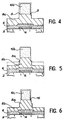
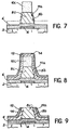
- FIGS. 1 to 9 illustrate the different stages of the method according to the invention.
- the first step of the method consists in producing, on a glass substrate 2, the gate 4 of the transistor using the conventional methods of photolithography (masking and etching).
- This grid 4, for example having a thickness of 100 nm is preferably made of chromium.
- an insulating layer preferably made of silicon oxide, is deposited on the substrate 2 and the gate 4 of the transistor.
- This insulating layer 6 having for example a thickness of 100 nm can be obtained by the chemical vapor deposition technique, at low pressure or not, or else by the glow discharge technique, in a radiofrequency device, using a gaseous mixture of SiH 4 and 0 2 .
- a first layer of thick hydrogenated amorphous silicon 8 advantageously having a thickness varying from 70 to 100 nm or close to 80 nm.
- This silicon layer can be obtained by the glow discharge technique using the gas SiH 4 .
- the next step of the process consists in depositing, on the thick amorphous silicon layer 8, a layer of positive photosensitive resin 10.
- This resin layer can advantageously have a thickness varying from 1,000 to 1,200 nm and can in particular be deposited by centrifugation.
- resin resins based on phenolformaldehyde such as that sold by the company Hunt under the reference HPR 204 can be used.
- the photosensitive resin layer 10 is then irradiated through the substrate 2, the grid 4 then serving as a mask for the irradiation.
- the use of a sensitive resin in the visible makes it possible to reduce the duration of this irradiation (the arrows shown in FIG. 2 indicate the direction of the irradiation).
- the next step, characteristic of the invention is the particular etching of the first layer of silicon 8 which makes it possible to produce a certain number of stair treads on the sides of this layer of silicon.
- the various operations carried out during this particular etching are represented in FIGS. 3 to 7 by dotted lines which thus make it possible to follow the progress of the process.
- the resin 10a is annealed at a temperature between 100 and 150 ° C. and preferably close to 130 ° C., to obtain a creep. of it.
- the etching used is a dry etching, using a sulfur hexafluoride plasma.
- the partial etching is at least equal to one third of the thickness of the initial hydrogenated amorphous silicon layer.
- the process which is the subject of the invention then consists in etching isotropically, a small thickness of resin.
- the etching shows on the top of the sides of the silicon layer 8a, a first step 9 of width equal to that of the etched resin layer.
- the etching used is a dry, ionic and reactive etching and the remaining resin 10b has a thickness of the order of 150 nm less than that of the initial resin 10a in FIG. 3.
- the etching of part of the thickness of the silicon layer is renewed, the remaining resin 10b serving as a mask for said etching.
- This second partial etching similarly attacks the step 9 and reveals a first step 9a on the flanks of the remaining silicon layer 8b.
- the isotropic etching is renewed in an identical manner, with a small thickness of resin 10b, which etching revealing a second step 11 on the top of the flanks of the silicon layer 8b, of the same length as the thickness of the etched resin layer.
- the etching operation of the silicon layer is repeated until the insulating layer 6 is exposed, the remaining resin 10c serving as a mask for said etching.
- This last partial etching similarly attacks the step 11 and the step 9a (FIG. 6) and reveals a second step 11 a which is added to the first step 9b on the sides of the remaining silicon layer 8c (Fig. .7).
- etchings produced in the silicon layer on the one hand and in the resin on the other hand be carried out respectively according to identical methods.
- dry etching using a sulfur hexafluoride plasma for the silicon layer, and an oxygen plasma for the resin.
- the fabrication of the transistor is completed by depositing, in a known manner over the entire structure, a second layer of amorphous silicon 12 of n + type, hydrogenated or not, having for example a thickness of 20 nm.
- This second silicon layer 12 deposited by the same technique as that used for the first silicon layer, allows the production of ohmic contacts for the source and the drain of the transistor.
- This layer 12 is then covered with a conductive layer 14 preferably made of chromium.
- This conductive layer 14 having for example a thickness of 150 nm, is obtained by deposition, for example by vacuum evaporation or by spraying.
- the electrodes of the source, drain of the transistor are produced by the conventional photolithography methods (masking and etching).
Landscapes
- Thin Film Transistor (AREA)
- Drying Of Semiconductors (AREA)
Claims (2)
dadurch gekennzeichnet, daß man im Verlaufe der Stufe g) eine bestimmte Anzahl von Treppenstufen auf den Flanken der Siliciumschicht (8) durch eine gleiche Anzahl von aufeinanderfolgenden und partiellen Gravierungen (Ätzungen) dieser Siliciumschicht (8) erzeugt, wobei das zurückbleibende Harz (10a) jedesmal als Maske dient und selbst in isotroper Weise auf eine geringe Dicke graviert (geätzt) wird am Ende jeder Gravierung (Atzung) der Siliciumschicht (8), wobei die erhaltenen Treppenstufen eine Länge haben, die gleich der Dicke des durch die isotrope Gravierung entfernten Harzes ist.
dadurch gekennzeichnet, daß die ersten Schichten aus hydriertem amorphem Silicium (8) Flanken in Form einer Treppe aufweisen, die aus mindestens zwei Stufen besteht.
Applications Claiming Priority (2)
| Application Number | Priority Date | Filing Date | Title |
|---|---|---|---|
| FR8516922 | 1985-11-15 | ||
| FR8516922A FR2590409B1 (fr) | 1985-11-15 | 1985-11-15 | Procede de fabrication d'un transistor en couches minces a grille auto-alignee par rapport au drain et a la source de celui-ci et transistor obtenu par le procede |
Publications (2)
| Publication Number | Publication Date |
|---|---|
| EP0222668A1 EP0222668A1 (de) | 1987-05-20 |
| EP0222668B1 true EP0222668B1 (de) | 1990-04-25 |
Family
ID=9324860
Family Applications (1)
| Application Number | Title | Priority Date | Filing Date |
|---|---|---|---|
| EP86402497A Expired - Lifetime EP0222668B1 (de) | 1985-11-15 | 1986-11-07 | Verfahren zum Herstellen eines Dünnschichttransistors mit in Bezug auf Source und Drain selbstausrichtendem Gate durch stufenweises Ätzen und danach hergestellter Transistor |
Country Status (5)
| Country | Link |
|---|---|
| US (1) | US4715930A (de) |
| EP (1) | EP0222668B1 (de) |
| JP (1) | JPS62124775A (de) |
| DE (1) | DE3670725D1 (de) |
| FR (1) | FR2590409B1 (de) |
Families Citing this family (29)
| Publication number | Priority date | Publication date | Assignee | Title |
|---|---|---|---|---|
| JPS63157476A (ja) * | 1986-12-22 | 1988-06-30 | Seiko Instr & Electronics Ltd | 薄膜トランジスタ |
| US4905319A (en) * | 1987-07-28 | 1990-02-27 | Syracuse University | Superconducting device including a thin chromium film with negative susceptibility |
| JPH01173650A (ja) * | 1987-12-26 | 1989-07-10 | Seikosha Co Ltd | 非晶質シリコン薄膜トランジスタの製造方法 |
| JPH0634401B2 (ja) * | 1987-12-29 | 1994-05-02 | 株式会社精工舎 | 遮光性薄膜のエッチング方法 |
| US4888632A (en) * | 1988-01-04 | 1989-12-19 | International Business Machines Corporation | Easily manufacturable thin film transistor structures |
| JPH0242761A (ja) * | 1988-04-20 | 1990-02-13 | Matsushita Electric Ind Co Ltd | アクティブマトリクス基板の製造方法 |
| FR2638880B1 (fr) * | 1988-11-08 | 1990-12-14 | France Etat | Procede de fabrication d'un ecran d'affichage a matrice de transistors pourvus d'un masque optique |
| US4902377A (en) * | 1989-05-23 | 1990-02-20 | Motorola, Inc. | Sloped contact etch process |
| US5010027A (en) * | 1990-03-21 | 1991-04-23 | General Electric Company | Method for fabricating a self-aligned thin-film transistor utilizing planarization and back-side photoresist exposure |
| DE69012555T2 (de) * | 1990-07-25 | 1995-04-06 | International Business Machines Corp., Armonk, N.Y. | Methode zur Herstellung von mikromechanischen Sensoren für AFM/STM/MFM-Profilometrie und mikromechanischer AFM/STM/MFM-Sensorkopf. |
| WO1992006490A1 (en) * | 1990-10-05 | 1992-04-16 | General Electric Company | Device self-alignment by propagation of a reference structure's topography |
| JP2658569B2 (ja) * | 1990-11-28 | 1997-09-30 | 日本電気株式会社 | 薄膜トランジスタおよびその製造方法 |
| GB9114018D0 (en) * | 1991-06-28 | 1991-08-14 | Philips Electronic Associated | Thin-film transistor manufacture |
| FR2719416B1 (fr) * | 1994-04-29 | 1996-07-05 | Thomson Lcd | Procédé de passivation des flancs d'un composant semiconducteur à couches minces. |
| JP2661594B2 (ja) * | 1995-05-25 | 1997-10-08 | 日本電気株式会社 | 薄膜トランジスタおよびその製造方法 |
| KR0167889B1 (ko) * | 1995-06-09 | 1999-02-01 | 김주용 | 반도체 소자의 비아홀의 형성방법 |
| US5597747A (en) * | 1995-12-15 | 1997-01-28 | Industrial Technology Research Institute | Method of making inverted thin film transistor using backsick exposure and negative photoresist |
| GB9600469D0 (en) * | 1996-01-10 | 1996-03-13 | Secr Defence | Three dimensional etching process |
| US5637519A (en) * | 1996-03-21 | 1997-06-10 | Industrial Technology Research Institute | Method of fabricating a lightly doped drain thin-film transistor |
| JPH1050607A (ja) * | 1996-07-31 | 1998-02-20 | Sony Corp | 半導体装置の製造方法 |
| US5899747A (en) * | 1997-01-27 | 1999-05-04 | Vanguard International Semiconductor Corporation | Method for forming a tapered spacer |
| KR100507344B1 (ko) | 2003-04-17 | 2005-08-08 | 삼성에스디아이 주식회사 | 박막 트랜지스터 및 그의 제조 방법 |
| JP5000084B2 (ja) * | 2003-08-13 | 2012-08-15 | 三星電子株式会社 | 導電パッドのシリンダースタックキャパシタにおけるストレージノード、半導体素子及び半導体素子の製造方法 |
| KR100546363B1 (ko) * | 2003-08-13 | 2006-01-26 | 삼성전자주식회사 | 콘케이브 형태의 스토리지 노드 전극을 갖는 반도체메모리 소자 및 그 제조방법 |
| TWI237395B (en) * | 2004-02-27 | 2005-08-01 | Au Optronics Corp | Method of fabricating thin film transistor array substrate and stacked thin film structure |
| JP5480480B2 (ja) * | 2007-09-03 | 2014-04-23 | 株式会社半導体エネルギー研究所 | 半導体装置の作製方法 |
| TWI473273B (zh) * | 2011-08-15 | 2015-02-11 | 友達光電股份有限公司 | 薄膜電晶體、畫素結構及其製造方法 |
| JP2019121750A (ja) * | 2018-01-11 | 2019-07-22 | 東京エレクトロン株式会社 | エッチング方法およびエッチング装置 |
| CN109065551B (zh) * | 2018-07-30 | 2020-01-14 | 深圳市华星光电技术有限公司 | Tft阵列基板的制造方法及tft阵列基板 |
Family Cites Families (8)
| Publication number | Priority date | Publication date | Assignee | Title |
|---|---|---|---|---|
| US3878008A (en) * | 1974-02-25 | 1975-04-15 | Us Navy | Method of forming high reliability mesa diode |
| JPS5673454A (en) * | 1979-11-21 | 1981-06-18 | Sumitomo Metal Mining Co Ltd | Manufacture of stepped semiconductor substrate |
| JPS5745256A (en) * | 1980-09-01 | 1982-03-15 | Fujitsu Ltd | Manufacture of semiconductor device |
| JPS57199223A (en) * | 1981-06-01 | 1982-12-07 | Matsushita Electric Ind Co Ltd | Manufacture of semiconductor device |
| US4404731A (en) * | 1981-10-01 | 1983-09-20 | Xerox Corporation | Method of forming a thin film transistor |
| US4461071A (en) * | 1982-08-23 | 1984-07-24 | Xerox Corporation | Photolithographic process for fabricating thin film transistors |
| US4514252A (en) * | 1982-11-18 | 1985-04-30 | Hewlett-Packard Company | Technique of producing tapered features in integrated circuits |
| FR2553579B1 (fr) * | 1983-10-12 | 1985-12-27 | Commissariat Energie Atomique | Procede de fabrication d'un transistor en film mince a grille auto-alignee |
-
1985
- 1985-11-15 FR FR8516922A patent/FR2590409B1/fr not_active Expired
-
1986
- 1986-11-07 DE DE8686402497T patent/DE3670725D1/de not_active Expired - Lifetime
- 1986-11-07 EP EP86402497A patent/EP0222668B1/de not_active Expired - Lifetime
- 1986-11-10 JP JP61265721A patent/JPS62124775A/ja active Pending
- 1986-11-13 US US06/929,908 patent/US4715930A/en not_active Expired - Fee Related
Also Published As
| Publication number | Publication date |
|---|---|
| FR2590409B1 (fr) | 1987-12-11 |
| EP0222668A1 (de) | 1987-05-20 |
| US4715930A (en) | 1987-12-29 |
| JPS62124775A (ja) | 1987-06-06 |
| DE3670725D1 (de) | 1990-05-31 |
| FR2590409A1 (fr) | 1987-05-22 |
Similar Documents
| Publication | Publication Date | Title |
|---|---|---|
| EP0222668A1 (de) | Verfahren zum Herstellen eines Dünnschichttransistors mit in Bezug auf Source und Drain selbstausrichtendem Gate durch stufenweises Ätzen und danach hergestellter Transistor | |
| EP0511096B1 (de) | Verfahren zur Lokalpassivierung eines Substrates mit einer amorphen wasserstoffhaltigen Kohlenstoffschicht und Verfahren zur Herstellung von Dünnschicht-Transistoren auf diesem passivierten Substrat | |
| EP0139585B1 (de) | Verfahren zum Herstellen eines Dünnfilmtransistors mit selbstausrichtendem Gate | |
| EP0166647B1 (de) | Verfahren zum Herstellen von wenigstens einem Dünnschichtfeldeffekttransistor und nach diesem Verfahren hergestellter Transistor | |
| EP0013342B1 (de) | Verfahren zur Herstellung selbstausrichtender Feldeffekt-Transistoren des Metallhalbleitertyps | |
| FR2734082A1 (fr) | Procede de fabrication d'un condensateur de stockage dans un dispositif d'affichage a cristaux liquides et dispositif d'affichage a cristaux liquides | |
| FR2585879A1 (fr) | Depot et durcissement du titane de l'electrode de grille pour emploi dans des transistors inverses a effet de champ a couche mince | |
| FR2761808A1 (fr) | Transistor en couche mince et son procede de fabrication | |
| EP0214033B1 (de) | Verfahren zur Herstellung eines Lichtbildsensors und linearer Bildsensor durch dieses Verfahren | |
| WO2020128354A1 (fr) | Substrat de type semi-conducteur sur isolant pour des applications radiofréquences | |
| EP0707237A1 (de) | Verfahren zur Herstellung von Löchern in Photoresistschichten, Anwendung für die Herstellung von Elektronenquelle mit Mikrospitzenemissionskathoden und flachen Bildschirmen | |
| FR2502399A1 (fr) | Dispositif a semi-conducteurs comportant un contact rapporte a faible resistance | |
| EP0415842B1 (de) | Verfahren zur Herstellung einer Anzeigetafel mit aktiver Matrix und invertierter Struktur | |
| EP0190243B1 (de) | Verfahren zur herstellung einer integrierten schaltung vom mis-typ | |
| EP0675544A1 (de) | Verfahren zur Herstellung eines Feldeffekttransistors mit isoliertem Gatter und kurzem Kanal, und entsprechender Transistor | |
| EP0058577B1 (de) | Halbleiteranordnung mit Elektronenablenkung vom Typ des "ballistischen Transportes" und Verfahren zum Herstellen einer solchen Anordnung | |
| EP0256053B1 (de) | Matrix aus zusammengeschalteten dünnschichttransistoren und ihre herstellung | |
| EP0570257A1 (de) | Feldeffekt-Halbleiteranordnung mit sekundärem Gate, Verfahren zur Herstellung und Verwendung in einer Matrix-Ansteuerungsanordnung | |
| EP0253727B1 (de) | Flüssigkristall-Anzeigetafel mit aktiver Matrix unter Verwendung amorphen hydrogenierten Siliciumcarbids und Verfahren zu ihrer Herstellung | |
| JP2864658B2 (ja) | 薄膜トランジスタの製造方法 | |
| EP0228316A1 (de) | Verfahren zum Herstellen eines Dünnschichttransistors und so hergestellter Transistor | |
| FR2631743A1 (fr) | Structure a electrodes non coplanaires pour affichage matriciel a cristaux liquides a transistors en couches minces de silicium amorphe et procede de fabrication | |
| EP0177422A1 (de) | Verfahren zum Herstellen von Gateelektroden aus Silicid oder aus Silicium für einen integrierten Schaltkreis mit Feldeffekttransistoren mit isolierter Gateelektrode | |
| WO2022175618A1 (fr) | Dispositif pyroelectrique comprenant un substrat a couche superficielle pyroelectrique et procede de realisation | |
| JPS61229370A (ja) | 光センサ素子の製造方法 |
Legal Events
| Date | Code | Title | Description |
|---|---|---|---|
| PUAI | Public reference made under article 153(3) epc to a published international application that has entered the european phase |
Free format text: ORIGINAL CODE: 0009012 |
|
| AK | Designated contracting states |
Kind code of ref document: A1 Designated state(s): CH DE GB IT LI NL |
|
| 17P | Request for examination filed |
Effective date: 19871024 |
|
| 17Q | First examination report despatched |
Effective date: 19890622 |
|
| GRAA | (expected) grant |
Free format text: ORIGINAL CODE: 0009210 |
|
| AK | Designated contracting states |
Kind code of ref document: B1 Designated state(s): CH DE GB IT LI NL |
|
| REF | Corresponds to: |
Ref document number: 3670725 Country of ref document: DE Date of ref document: 19900531 |
|
| ITF | It: translation for a ep patent filed | ||
| GBT | Gb: translation of ep patent filed (gb section 77(6)(a)/1977) | ||
| PLBE | No opposition filed within time limit |
Free format text: ORIGINAL CODE: 0009261 |
|
| STAA | Information on the status of an ep patent application or granted ep patent |
Free format text: STATUS: NO OPPOSITION FILED WITHIN TIME LIMIT |
|
| 26N | No opposition filed | ||
| ITTA | It: last paid annual fee | ||
| PGFP | Annual fee paid to national office [announced via postgrant information from national office to epo] |
Ref country code: GB Payment date: 19921027 Year of fee payment: 7 |
|
| PGFP | Annual fee paid to national office [announced via postgrant information from national office to epo] |
Ref country code: DE Payment date: 19921030 Year of fee payment: 7 |
|
| PGFP | Annual fee paid to national office [announced via postgrant information from national office to epo] |
Ref country code: CH Payment date: 19921116 Year of fee payment: 7 |
|
| PGFP | Annual fee paid to national office [announced via postgrant information from national office to epo] |
Ref country code: NL Payment date: 19921130 Year of fee payment: 7 |
|
| PG25 | Lapsed in a contracting state [announced via postgrant information from national office to epo] |
Ref country code: GB Effective date: 19931107 |
|
| PG25 | Lapsed in a contracting state [announced via postgrant information from national office to epo] |
Ref country code: LI Effective date: 19931130 Ref country code: CH Effective date: 19931130 |
|
| PG25 | Lapsed in a contracting state [announced via postgrant information from national office to epo] |
Ref country code: NL Effective date: 19940601 |
|
| GBPC | Gb: european patent ceased through non-payment of renewal fee |
Effective date: 19931107 |
|
| NLV4 | Nl: lapsed or anulled due to non-payment of the annual fee | ||
| REG | Reference to a national code |
Ref country code: CH Ref legal event code: PL |
|
| PG25 | Lapsed in a contracting state [announced via postgrant information from national office to epo] |
Ref country code: DE Effective date: 19940802 |
|
| PG25 | Lapsed in a contracting state [announced via postgrant information from national office to epo] |
Ref country code: IT Free format text: LAPSE BECAUSE OF NON-PAYMENT OF DUE FEES;WARNING: LAPSES OF ITALIAN PATENTS WITH EFFECTIVE DATE BEFORE 2007 MAY HAVE OCCURRED AT ANY TIME BEFORE 2007. THE CORRECT EFFECTIVE DATE MAY BE DIFFERENT FROM THE ONE RECORDED. Effective date: 20051107 |