EP0256827A2 - Gerät zur Datenaufzeichnung und -wiedergabe auf oder von einer optischen Platte - Google Patents
Gerät zur Datenaufzeichnung und -wiedergabe auf oder von einer optischen Platte Download PDFInfo
- Publication number
- EP0256827A2 EP0256827A2 EP87307067A EP87307067A EP0256827A2 EP 0256827 A2 EP0256827 A2 EP 0256827A2 EP 87307067 A EP87307067 A EP 87307067A EP 87307067 A EP87307067 A EP 87307067A EP 0256827 A2 EP0256827 A2 EP 0256827A2
- Authority
- EP
- European Patent Office
- Prior art keywords
- power
- recording
- optical disc
- area
- setting means
- Prior art date
- Legal status (The legal status is an assumption and is not a legal conclusion. Google has not performed a legal analysis and makes no representation as to the accuracy of the status listed.)
- Granted
Links
Images


Classifications
-
- G—PHYSICS
- G11—INFORMATION STORAGE
- G11B—INFORMATION STORAGE BASED ON RELATIVE MOVEMENT BETWEEN RECORD CARRIER AND TRANSDUCER
- G11B11/00—Recording on or reproducing from the same record carrier wherein for these two operations the methods are covered by different main groups of groups G11B3/00 - G11B7/00 or by different subgroups of group G11B9/00; Record carriers therefor
- G11B11/10—Recording on or reproducing from the same record carrier wherein for these two operations the methods are covered by different main groups of groups G11B3/00 - G11B7/00 or by different subgroups of group G11B9/00; Record carriers therefor using recording by magnetic means or other means for magnetisation or demagnetisation of a record carrier, e.g. light induced spin magnetisation; Demagnetisation by thermal or stress means in the presence or not of an orienting magnetic field
- G11B11/105—Recording on or reproducing from the same record carrier wherein for these two operations the methods are covered by different main groups of groups G11B3/00 - G11B7/00 or by different subgroups of group G11B9/00; Record carriers therefor using recording by magnetic means or other means for magnetisation or demagnetisation of a record carrier, e.g. light induced spin magnetisation; Demagnetisation by thermal or stress means in the presence or not of an orienting magnetic field using a beam of light or a magnetic field for recording by change of magnetisation and a beam of light for reproducing, i.e. magneto-optical, e.g. light-induced thermomagnetic recording, spin magnetisation recording, Kerr or Faraday effect reproducing
- G11B11/10595—Control of operating function
-
- G—PHYSICS
- G11—INFORMATION STORAGE
- G11B—INFORMATION STORAGE BASED ON RELATIVE MOVEMENT BETWEEN RECORD CARRIER AND TRANSDUCER
- G11B11/00—Recording on or reproducing from the same record carrier wherein for these two operations the methods are covered by different main groups of groups G11B3/00 - G11B7/00 or by different subgroups of group G11B9/00; Record carriers therefor
- G11B11/10—Recording on or reproducing from the same record carrier wherein for these two operations the methods are covered by different main groups of groups G11B3/00 - G11B7/00 or by different subgroups of group G11B9/00; Record carriers therefor using recording by magnetic means or other means for magnetisation or demagnetisation of a record carrier, e.g. light induced spin magnetisation; Demagnetisation by thermal or stress means in the presence or not of an orienting magnetic field
- G11B11/105—Recording on or reproducing from the same record carrier wherein for these two operations the methods are covered by different main groups of groups G11B3/00 - G11B7/00 or by different subgroups of group G11B9/00; Record carriers therefor using recording by magnetic means or other means for magnetisation or demagnetisation of a record carrier, e.g. light induced spin magnetisation; Demagnetisation by thermal or stress means in the presence or not of an orienting magnetic field using a beam of light or a magnetic field for recording by change of magnetisation and a beam of light for reproducing, i.e. magneto-optical, e.g. light-induced thermomagnetic recording, spin magnetisation recording, Kerr or Faraday effect reproducing
- G11B11/10532—Heads
- G11B11/10534—Heads for recording by magnetising, demagnetising or transfer of magnetisation, by radiation, e.g. for thermomagnetic recording
- G11B11/10536—Heads for recording by magnetising, demagnetising or transfer of magnetisation, by radiation, e.g. for thermomagnetic recording using thermic beams, e.g. lasers
-
- G—PHYSICS
- G11—INFORMATION STORAGE
- G11B—INFORMATION STORAGE BASED ON RELATIVE MOVEMENT BETWEEN RECORD CARRIER AND TRANSDUCER
- G11B11/00—Recording on or reproducing from the same record carrier wherein for these two operations the methods are covered by different main groups of groups G11B3/00 - G11B7/00 or by different subgroups of group G11B9/00; Record carriers therefor
- G11B11/10—Recording on or reproducing from the same record carrier wherein for these two operations the methods are covered by different main groups of groups G11B3/00 - G11B7/00 or by different subgroups of group G11B9/00; Record carriers therefor using recording by magnetic means or other means for magnetisation or demagnetisation of a record carrier, e.g. light induced spin magnetisation; Demagnetisation by thermal or stress means in the presence or not of an orienting magnetic field
- G11B11/105—Recording on or reproducing from the same record carrier wherein for these two operations the methods are covered by different main groups of groups G11B3/00 - G11B7/00 or by different subgroups of group G11B9/00; Record carriers therefor using recording by magnetic means or other means for magnetisation or demagnetisation of a record carrier, e.g. light induced spin magnetisation; Demagnetisation by thermal or stress means in the presence or not of an orienting magnetic field using a beam of light or a magnetic field for recording by change of magnetisation and a beam of light for reproducing, i.e. magneto-optical, e.g. light-induced thermomagnetic recording, spin magnetisation recording, Kerr or Faraday effect reproducing
- G11B11/10532—Heads
- G11B11/10541—Heads for reproducing
- G11B11/10543—Heads for reproducing using optical beam of radiation
-
- G—PHYSICS
- G11—INFORMATION STORAGE
- G11B—INFORMATION STORAGE BASED ON RELATIVE MOVEMENT BETWEEN RECORD CARRIER AND TRANSDUCER
- G11B11/00—Recording on or reproducing from the same record carrier wherein for these two operations the methods are covered by different main groups of groups G11B3/00 - G11B7/00 or by different subgroups of group G11B9/00; Record carriers therefor
- G11B11/10—Recording on or reproducing from the same record carrier wherein for these two operations the methods are covered by different main groups of groups G11B3/00 - G11B7/00 or by different subgroups of group G11B9/00; Record carriers therefor using recording by magnetic means or other means for magnetisation or demagnetisation of a record carrier, e.g. light induced spin magnetisation; Demagnetisation by thermal or stress means in the presence or not of an orienting magnetic field
- G11B11/105—Recording on or reproducing from the same record carrier wherein for these two operations the methods are covered by different main groups of groups G11B3/00 - G11B7/00 or by different subgroups of group G11B9/00; Record carriers therefor using recording by magnetic means or other means for magnetisation or demagnetisation of a record carrier, e.g. light induced spin magnetisation; Demagnetisation by thermal or stress means in the presence or not of an orienting magnetic field using a beam of light or a magnetic field for recording by change of magnetisation and a beam of light for reproducing, i.e. magneto-optical, e.g. light-induced thermomagnetic recording, spin magnetisation recording, Kerr or Faraday effect reproducing
- G11B11/1055—Disposition or mounting of transducers relative to record carriers
- G11B11/10576—Disposition or mounting of transducers relative to record carriers with provision for moving the transducers for maintaining alignment or spacing relative to the carrier
- G11B11/10578—Servo format, e.g. prepits, guide tracks, pilot signals
-
- G—PHYSICS
- G11—INFORMATION STORAGE
- G11B—INFORMATION STORAGE BASED ON RELATIVE MOVEMENT BETWEEN RECORD CARRIER AND TRANSDUCER
- G11B7/00—Recording or reproducing by optical means, e.g. recording using a thermal beam of optical radiation by modifying optical properties or the physical structure, reproducing using an optical beam at lower power by sensing optical properties; Record carriers therefor
- G11B7/004—Recording, reproducing or erasing methods; Read, write or erase circuits therefor
-
- G—PHYSICS
- G11—INFORMATION STORAGE
- G11B—INFORMATION STORAGE BASED ON RELATIVE MOVEMENT BETWEEN RECORD CARRIER AND TRANSDUCER
- G11B7/00—Recording or reproducing by optical means, e.g. recording using a thermal beam of optical radiation by modifying optical properties or the physical structure, reproducing using an optical beam at lower power by sensing optical properties; Record carriers therefor
- G11B7/12—Heads, e.g. forming of the optical beam spot or modulation of the optical beam
- G11B7/125—Optical beam sources therefor, e.g. laser control circuitry specially adapted for optical storage devices; Modulators, e.g. means for controlling the size or intensity of optical spots or optical traces
- G11B7/126—Circuits, methods or arrangements for laser control or stabilisation
-
- G—PHYSICS
- G11—INFORMATION STORAGE
- G11B—INFORMATION STORAGE BASED ON RELATIVE MOVEMENT BETWEEN RECORD CARRIER AND TRANSDUCER
- G11B7/00—Recording or reproducing by optical means, e.g. recording using a thermal beam of optical radiation by modifying optical properties or the physical structure, reproducing using an optical beam at lower power by sensing optical properties; Record carriers therefor
- G11B7/007—Arrangement of the information on the record carrier, e.g. form of tracks, actual track shape, e.g. wobbled, or cross-section, e.g. v-shaped; Sequential information structures, e.g. sectoring or header formats within a track
- G11B7/00745—Sectoring or header formats within a track
Definitions
- the present invention relates to an apparatus for recording and reproducing data into/from an optical disc in which data based on an information signal can be erased and rerecorded and, more particularly but not exclusively, to the control of the output of a laser diode for use in a light source of such a data recording and reproducing apparatus.
- Read-only optical discs e.g., compact disc, optical video disc, etc.
- data based on various kinds of information signals cannot be erased and rerecorded at all
- write-once type optical discs in which data can be recorded but cannot be erased
- optical discs in which data based on various kinds of information signals can be erased and rerecorded.
- type of such a disc is a magnetooptic disc.
- a magneto-optic disc data is recorded by the direction of magnetization in a manner similar to the perpendicular magnetic recording system.
- a perpendicular magnetization film in which the magnetization direction is oriented perpendicularly to the disc surface is used as a recording medium.
- This recording medium has a coercive force at ordinary temperatures, the magnetization direction does not change, and in the initial state before data is recorded and in the state in which previously recorded data has been erased, the magnetization direction is orientated in a constant direction.
- a recording beam e.g., a laser beam is irradiated onto the recording medium, the temperature of the beam irradiated portion rapidly increases. When the temperature has reached a Curie temperature or compensation temperature, the coercive force decreases.
- a weak magnetic field is applied from the outside by an external magnetic field generating means.
- the recording beam e.g., laser beam onto the recording medium of the disc
- the temperature of the beam irradiated portion promptly increases and the magnetization direction of the recording medium is reversed in accordance with the direction of the magnetic field generated from the external magnetic field generating means.
- a reproducing beam e.g., a laser beam having a power which is sufficiently smaller than the irradiation power when data is written is irradiated onto the disc, and the rotational angle of the rectilinear plane of polarization of the reflected light is detected.
- the direction of the magnetic field which is generated from the external magnetic field generating means is held constant and at the same time, by irradiating with an erasing beam, e.g., a laser beam onto a desired portion of the recording medium of the disc, the magnetization direction of the recording medium is oriented to a constant direction in accordance with the direction of the magnetic field generated from the external magnetic field generating means on a basis similar to that when data is written. In this manner, data is erased.
- an erasing beam e.g., a laser beam onto a desired portion of the recording medium of the disc
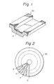
- a guide groove 31 for tracking is formed in such an erasable and rerecordable optical disc 30.
- a laser beam is emitted from a laser light source of an optical head (not shown) which can be freely moved in the radial direction of the optical disc.
- a tracking servo is applied to an objective lens drive apparatus (not shown) of the optical head so that the emitted laser beam can trace along the guide groove 31, so that data is recorded along the guide groove 31.
- an area of the disc 30 is divided into, e.g., 32 sectors per rotation. Data is read out of, or written into, every sector.
- a laser beam is used to read out and write data.
- a laser diode can be used as the laser beam emitting source.
- the optimum value of the power of the laser beam differs in each of the reading, writing, and erasing modes. Namely, as mentioned above, in the case of writing data, in order to reverse the magnetization direction of the recording medium of the optical disc, the laser beam from the laser diode irradiated onto the recording medium needs to raise the temperature of medium to a temperature near the Curie temperature or the compensation temperature. Therefore, the largest power is necessary in the writing mode.
- the temperature of the irradiated portion of the recording medium does not reach the Curie temperature, so that the magnetization direction cannot be reversed. Therefore, data is not adequately written.
- the power is too large in the reading mode, further data may be written by the reading laser beam onto data which has already been written onto the disc, so that the written data may be corrupted.
- the power of a laser diode changes a great amount with its temperature and it can also vary by a large amount with the elapse of time.
- a servo circuit adapted to keep the power of the laser diode at an optimum value.
- APC automatic power control
- Fig. 4 shows an example of an APC circuit for use in a conventional magneto-optic disc recording and reproducing apparatus.
- a laser diode 21 is a light source.
- a laser beam from the laser diode 21 is irradiated onto a magneto-optic disc.
- the light emission power of the laser diode 21 is detected by a monitoring photo diode 22 disposed near the laser diode 21.
- monitor lights In general, light fluxes corresponding to the intensity of the emitted laser beam are also emitted from both of the edge surfaces of the laser diode to emit a laser beam onto the disc side and the edge surface on the opposite side (these fluxes are referred to as "monitor lights". These monitor lights are detected by the photo diode 22. The intensity of the monitor lights received by the photo diode 22 varies according to the light emission power of the laser diode 21 and a current corresponding to the received monitor lights flows through the photo diode 22.
- the detection current of the photo diode 22 is converted into a voltage value by a current-voltage (I-V) converting circuit 23.
- An output of the I-V converting circuit 23 is supplied to a comparator 24.
- Target voltages Vr11, Vr12, and Vr13 are selectively supplied to the comparator 24 through a switch 25 depending on the operating mode (writing/erasing/reading). Namely, when terminals 25A and 25D of the switch 25 are connected, the target voltage Vr11 in the writing mode is supplied from a voltage source 26A to the comparator 24. When terminals 25B and 25D are connected, the target voltage Vr12 in the erasing mode is supplied from a voltage source 26B to the comparator 24.
- the target voltage Vr13 in the reading mode is supplied from a voltage source 26C to the comparator 24.
- each target voltage is selectively supplied to the comparator 24 by switch 25 whose switching operation is controlled by control means (not shown) in accordance with each of the writing, erasing, and reading modes.
- the output of the comparator 24 is supplied to a current limiter 28 through a low pass filter 27.
- the current limiter 28 is provided to prevent excessive current flow through the laser diode 21 which would damage it.
- An output of the current limiter 28 is supplied to a drive circuit 29.
- An output of the drive circuit 29 is supplied to the laser diode 21.
- a laser beam corresponding in intensity to the output of the drive circuit 29 is emitted from the laser diode 21 and irradiated onto a magneto-optic disc.
- a modulation signal based on an information signal to be recorded is supplied from a terminal 32 to the drive circuit 29.
- the laser beam is modulated by the modulation signal and the switch 25 is switched by control means (not shown) and a beam having a predetermined power in the writing mode is generated by the laser diode 21.
- the output of the laser diode 21 is detected by the photo diode 22.
- the detection output of the photo diode 22 is compared with the target value in each of the writing, erasing, and reading modes by the comparator 24.
- the light emission output of the laser diode 21 is controlled so as to become constant at the target value in each of the writing, erasing, and reading modes in accordance with the output of the comparator 24.
- the APC circuit it takes a time for the APC circuit to become stable. Namely, for example, when the operating mode was changed from the reading mode to the writing mode, the target voltage is switched from Vr13 to Vr11 and the light emission power of the laser diode 21 is increased. However, the power of the laser diode 21 does not immediately rise to the target value in the writing mode from the target value in the reading mode and is not stable until it reaches the target value. Therefore, as shown in Fig.2, a conventional optical disc is provided with a gap G between sectors. No effective data is recorded in the gap G. After the operation of the APC circuit stabilizes, the writing, reading, or erasing operation is performed.
- the guide groove 31 for tracking is provided in a conventional optical disc.
- Such a guide groove 31 causes the problems that noise from the guide groove 31 is picked up, the carrier-to-noise (C/N) ratio deteriorates and the reliability of data also deteriorates.
- a method whereby a tracking servo is applied without forming the guide groove 31 has been considered. For example, as disclosed in U.S.P. No.
- a plurality of servo areas are provided in a disc and servo pits for tracking are formed in the servo areas.
- the tracking servo is applied in the servo area interval on the basis of tracking error information which is obtained from the servo pits.
- the response speed of the APC circuit becomes a problem. Namely, in the case where the tracking control was performed by the foregoing method, the servo area is set into the reading mode in order to read out the servo pits. Since the servo area enters the reading mode, in the case of writing data into a disc, it is necessary to set the power of the laser diode at the optimum value in the reading mode in the servo area and the power of the laser diode needs to be immediately set to the optimum value in the writing mode in a recording area. Namely, in Fig.
- the terminals 25C and 25D are connected when reading the servo area and the terminals 25A and 25D are connected when writing in the recording area.
- the power of the laser diode does not promptly become the optimum value.
- a gap such as the gap G provided between sectors as shown in Fig. 2 is formed between the servo area and the recording area.
- the formation of gaps again results in a decrease in recording density of the disc in a manner similar to the case of the optical disc in Fig. 2..
- Consideration has also been given to omitting the low pass filter 27 in order to increase the operating speed of the APC circuit.
- the operation of the APC circuit is not stable.
- an object of the present invention to provide an apparatus for recording and reproducing data into/from an optical disc in which the power of the laser beam can be instantaneously controlled to the optimum value in each of the writing, reading and erasing modes without reducing a recording density.
- an apparatus for recording and reproducing data into/from an optical disc comprising: a detector for detecting the light emission power of said laser light source; power setting means for comparing the detected light emission power with a target value, and for setting the light emission power of the laser light source on the basis of a comparison output; and drive means for driving said laser light source on the basis of the power set by said power setting means; characterised in that, the optical disc being one in which a part of a recording area is provided with an extracting area to sample and hold a detection output derived by detecting the light emission power of the laser light source, the power setting means is arranged to sample and hold the detection output from said detector, to compare said sampled and held value with a target value, and to set the light emission power of the laser light source on the basis of a comparison output; and in that the light emission power of said laser light source is controlled on the basis of the value sampled and held by said power setting means in said extracting area.
- a second aspect of the invention provides an optical disc having an optical recorded medium which consists of a plurality of tracks and into which an information signal can be optically recorded, characterized in that a part of a recording area of said information signal is provided with an extracting area to set the light emission power of a laser light source to be used to record and reproduce said information signal.
- This aspect of the invention also provides an optical disc having an optical recording medium which consists of a plurality of tracks and into and from which an information signal can be optically recorded and erased, characterised in that a part of a recording area of said information signal is provided with an extracting area to set the light emission power of a laser light source to be used to record, erase, and reproduce said information signal.
- the power of the laser diode 1 is detected by the photo diode 2.
- the detection output in a servo area SA1 is held in a sample and hold circuit 4C.
- the detection output in a servo area SA2 is stored in sample and hold circuits 4A and 4B.
- the power of the laser diode 1 in the reading mode is controlled on the basis of the detection output held in the sample and hold circuit 4C.
- the powers of the laser diode 1 in the writing and reading modes are controlled on the basis of the detection outputs held in the sample and hold circuits 4A and 4B. Due to this, the APC loop in the writing, erasing, or reading mode becomes stable. Therefore, when the operating mode was switched, the light emission power of the laser diode 1 can be immediately set to a target value.
- a magnetic-optic disc which is used with the embodiment is formed with a plurality of, e.g., 1300 servo areas SA per circumference.
- tracking control is performed for an objective lens drive apparatus (not shown) of an optical head (not shown) which is controlled such that a laser beam emitted from a laser diode is focused onto the surface of a recording medium of a magneto-optic disc. Therefore, a guide groove for a tracking servo such as shown in Fig.1 is not provided.
- the servo area SA further consists of a servo area SA1 and a servo area SA2. As shown in Fig.6, pits P1, P2, and P3 are formed in the servo area SA1.
- the pits P1 and P2 are used to perform tracking control for the objective lens drive apparatus. Namely, the pits P1 and P2 are arranged at positions which deviate in the opposite directions from the centre of track T.
- the operating mode is set to the reading mode and tracking servo is applied to the objective lens drive apparatus so that the signal reproduced from the pits P1 and P2 are equalized.
- the laser beam scans the centre between the pits P1 and P2, i.e., the centre line of the track T.
- the pit P3 is provided to form a reference signal to reproduce a bit clock.
- An area in which no pit is formed is provided in the portion between the pit P2 and the pit P3.
- the servo area SA2 is provided.
- the area in which no pit is formed and the servo area SA2 are provided to control the operation of the APC circuit of the laser diode and will be explained in detail hereinafter.
- Fig.7 shows an embodiment of the invention.
- reference numeral 1 denotes a laser diode.
- a laser beam emitted from the laser diode 1 is irradiated onto an optical disc.
- the light emission power of the laser diode 1 is detected by a monitoring photo diode 2 disposed near the laser diode 1 as mentioned above. Namely, the light fluxes which are emitted from the edge surfaces of the laser diode while it is irradiated onto the magneto-optic disc are received by the photo diode 2.
- a current corresponding to the received light fluxes flows through the photo diode 2.
- the current flowing through the photo diode 2 is converted into a voltage value by an I-V converting circuit 3.
- An output of the I-V converting circuit 3 is supplied to sample and hold circuits 4A, 4B and 4C.
- Sampling pulses SBW, SBE, and SBR are respectively supplied from terminals 12A, 12B and 12C to the sample and hold circuits 4A, 4B and 4C.
- the sampling pulses SBW, SBE and SBR are generated at timings as shown in Fig.8.
- the sampling pulses SBW, SBE and SBR are respectively set to the high level, the output of the I-V converting circuit 3 is sampled and held in the corresponding one of the sample and hold circuits 4A, 4B and 4C.
- the outputs of the sample and hold circuits 4A, 4B and 4C are supplied to comparators 5A, 5B, and 5C respectively.
- Target voltages Vr1, Vr2 and Vr3 are applied from voltage sources 6A, 6B and 6C to the comparators 5A, 5B and 5C respectively.
- the voltage Vr1 corresponds to the target power in the writing mode.
- the voltage Vr2 corresponds to the target power in the erasing mode.
- the voltage Vr3 corresponds to the target power in the reading mode.
- Comparison outputs of the comparators 5A, 5B, and 5C are supplied to current limiters 8A, 8B and 8C through low pass filters 7A, 7B, and 7C, respectively.
- the current limiters 8A to 8C are provided to prevent damaging excessive currents from passing through the laser diode 1.
- Outputs of the current limiters 8A to 8C are selectively supplied to a drive circuit 10 through a switch 9.
- the switch 9 is appropriately switched by control means (not shown) in accordance with the reading, erasing or writing mode. Namely, terminals 9A to 9D of the switch 9 are connected in the writing mode and the output of the current limiter 8A is supplied to the drive circuit 10.
- terminals 9B and 9D are connected and the output of the current limiter 8B is supplied to the drive circuit 10.
- terminals 9C and 9D are connected and the output of the current limiter 8C is supplied to the drive circuit 10.
- an output of the drive circuit 10 corresponding to the output from the current limiter connected by the switch 9 is supplied to the laser diode 1.
- the light emission power of the laser diode 1 is controlled in accordance with the output of the drive circuit 10.
- a laser beam modulated by the modulation signal is set to the optimum power level in the writing mode on the basis of the output of the current limiter 8A by the switch 9 and output from the laser diode 1. This laser beam is irradiated onto the recording medium of the disc.
- the servo area SA1 and the servo area SA2 subsequent to the servo area SA1 are formed in the magneto-optic disc. Therefore, when the magneto-optic disc is rotated by rotation driving means (not shown), as shown in Fig.8A, the laser beam from the laser diode 1 scans the servo areas SA1 and SA2 between data areas DA. As shown in Fig.8B, the sampling pulse SBR which is supplied to the sample and hold circuit 4C is set to the high level for the period of time corresponding to the area in which no pit is formed in the servo area SA1.
- the sampling pulsed SBW and SBE which are supplied to the sample and hold circuits 4A and 4B area alternately set to the high level every area for the period of time corresponding to the servo area SA2 as shown in Figs.8C and 8D.
- the detection output of the photo diode 2 is held in the sample and hold circuit 4C.
- the output of the sample and hold circuit 4C is compared with the target value Vr3 by the comparator 5C.
- the comparison output is supplied to the low pass filter 7C.
- the detection output of the photo diode 2 is alternately held in the sample and hold circuits 4A and 4B for each area.
- the outputs of the sample and hold circuits 4A and 4B are respectively supplied to the comparators 5A and 5B.
- the comparison outputs of the comparators 5A and 5B are supplied to the low pass filters 7A and 7B, respectively.
- the power of the laser diode 1 is controlled to the optimum value in the reading mode on the basis of the detection output of the photo diode 2 in the area in the servo area SA1.
- the power of the laser diode 1 is controlled to the optimum power in each of the writing and erasing modes on the basis of the detection output of the photo diode 2 in the servo area SA2.
- the detection output in the area in the servo area SA1 and the detection output in the servo area SA2 are sampled and held in the sample and hold circuits 4A, 4B and 4C a plurality of times. These detection outputs are sequentially compared with the target values by the comparators 5A, 5B, and 5C, thereby enabling the automatic power control to become stable.
- the optimum values in the writing, erasing, and reading modes are stored in the low pass filters 7A, 7B and 7C respectively.
- the optimum values in the writing, erasing, and reading modes are respectively stored in the low pass filters 7A, 7B and 7C.
- the automatic power control loops in the writing, erasing, and reading modes are respectively stable.
- the output of the laser diode 1 is immediately set to the appropriate target value in correspondence to the switched mode.
- the detection output is alternately held in the sample and hold circuits 4A and 4B for each area in the servo area SA2.
- the time-dependent change component of the laser diode 1 is sufficiently low, no problem occurs even if the detection output is alternately sampled for each area in this manner.
- the laser diode 1 in the reading mode is controlled by use of the detection output which was sampled in the area in which no pit is formed. Therefore, the laser diode 1 can be controlled in the optimum state without being influenced by modulation components due to the guide groove.
- the embodiment of the invention has been described with respect to a magneto-optic disc recording and reproducing apparatus of the optical modulation system in which by supplying a modulation signal based on an information signal to the drive circuit 10 of the laser diode 1, a laser beam emitted from the laser diode 1, i.e., a recording beam is modulated, thereby recording the information signal.
- the invention can be also applied to a magnetic field modulation system in which a modulation signal based on an information signal is supplied to external magnetic field generating means (not shown) which is used to reverse the magnetization direction and a drive signal at a DC level necessary to record or erase is supplied from the drive circuit 10 to the laser diode 1.
- the invention is not limited to only a magneto-optic disc, but can be also applied to unerasable optical discs of the phase transition type, write-once type and the like.
- the detection output in the servo area SA1 is sampled and held in the sample and hold circuit 4C and the detection output in the servo area SA2 is sampled and held in the sample and hold circuits 4A and 4B.
- the power of the laser diode 1 in the reading mode is controlled on the basis of the detection outputs sampled and held in the sample and hold circuit 4C.
- the power of the laser diode 1 in the writing and reading modes is controlled on the basis of the detection outputs sampled and held in the sample and hold circuits 4A and 4B. Therefore, when the operating mode is switched between the writing, erasing, and reading modes, the power of the laser diode 1 can be immediately set to the required target value.
- control loops in the reading, writing and erasing modes are individually constituted. Therefore, the characteristic of the loop in each mode can be optimized.
- control loop is individually controlled in each mode, the current limiters 8A, 8B and 8C can be optimized in each mode and reliability can improved.
- the recording area of a disc can be effectively used without decreasing recording density of disc.
- the additional time until the power of the laser diode rises is eliminated. Even if the operating mode is switched, the power of the laser diode immediately rises. Therefore, an apparatus having a high response speed can be realized.
Landscapes
- Physics & Mathematics (AREA)
- Optics & Photonics (AREA)
- Optical Recording Or Reproduction (AREA)
- Optical Head (AREA)
Priority Applications (1)
| Application Number | Priority Date | Filing Date | Title |
|---|---|---|---|
| AT87307067T ATE84375T1 (de) | 1986-08-13 | 1987-08-10 | Geraet zur datenaufzeichnung und -wiedergabe auf oder von einer optischen platte. |
Applications Claiming Priority (2)
| Application Number | Priority Date | Filing Date | Title |
|---|---|---|---|
| JP61188388A JPH07111782B2 (ja) | 1986-08-13 | 1986-08-13 | 光デイスクの記録再生装置 |
| JP188388/86 | 1986-08-13 |
Publications (3)
| Publication Number | Publication Date |
|---|---|
| EP0256827A2 true EP0256827A2 (de) | 1988-02-24 |
| EP0256827A3 EP0256827A3 (en) | 1989-01-04 |
| EP0256827B1 EP0256827B1 (de) | 1993-01-07 |
Family
ID=16222754
Family Applications (1)
| Application Number | Title | Priority Date | Filing Date |
|---|---|---|---|
| EP87307067A Expired - Lifetime EP0256827B1 (de) | 1986-08-13 | 1987-08-10 | Gerät zur Datenaufzeichnung und -wiedergabe auf oder von einer optischen Platte |
Country Status (7)
| Country | Link |
|---|---|
| US (1) | US4796250A (de) |
| EP (1) | EP0256827B1 (de) |
| JP (1) | JPH07111782B2 (de) |
| KR (1) | KR950013701B1 (de) |
| AT (1) | ATE84375T1 (de) |
| DE (1) | DE3783406T2 (de) |
| HK (1) | HK95995A (de) |
Cited By (14)
| Publication number | Priority date | Publication date | Assignee | Title |
|---|---|---|---|---|
| EP0400726A1 (de) * | 1989-05-29 | 1990-12-05 | Koninklijke Philips Electronics N.V. | Verfahren und Gerät zur Aufzeichnung von Signalen auf einem Aufzeichnungsträger, Messverfahren und Messvorrichtung zur Anwendung in der Aufzeichnungsmethode und dem Aufzeichnungsgerät und Aufzeichnungsträger |
| EP0404249A1 (de) * | 1989-06-23 | 1990-12-27 | Koninklijke Philips Electronics N.V. | Verfahren und Vorrichtung zum Einstellen von Aufzeichnungsparametern |
| EP0420249A3 (en) * | 1989-09-29 | 1991-05-29 | Kabushiki Kaisha Toshiba | Optical disk apparatus having stabilizing function for outputting laser beam |
| EP0422227A4 (en) * | 1988-12-16 | 1992-01-02 | Sony Corporation | Optical disc recording/reproducing apparatus |
| EP0405952A3 (en) * | 1989-06-28 | 1992-03-04 | Sharp Kabushiki Kaisha | Semiconductor laser driving circuit |
| EP0478329A1 (de) * | 1990-09-28 | 1992-04-01 | International Business Machines Corporation | Eichung des Lichtstrahles eines optischen Datenspeichersystemes bei Einführung eines Speicherelementes |
| EP0549138A1 (de) * | 1991-11-25 | 1993-06-30 | Sharp Kabushiki Kaisha | Magneto-optische Scheibe und Wiedergabeverfahren dafür |
| EP0582996A1 (de) * | 1992-08-10 | 1994-02-16 | Sharp Kabushiki Kaisha | Lichtmengensteuereinrichtung für Gerät zur Aufzeichnung und Wiedergabe von optischen Platten |
| EP0652615A3 (de) * | 1993-11-08 | 1995-09-06 | Nippon Kogaku Kk | Laserleistungsüberwachungsschaltung verwendet in einem magnetooptischen Plattengerät. |
| EP0713214A3 (de) * | 1994-11-17 | 1996-09-18 | Matsushita Electric Industrial Co Ltd | Verfahren und Vorrichtung zur Regelung der Leistung einer Mehrstrahlhalbleiterlaservorrichtung |
| US5835476A (en) * | 1988-07-18 | 1998-11-10 | Sony Corporation | Laser diode driving apparatus |
| WO1999052103A1 (en) * | 1998-04-03 | 1999-10-14 | Samsung Electronics Co., Ltd. | Adaptive recording method and apparatus for high-density optical recording apparatus |
| CN1096060C (zh) * | 1995-04-05 | 2002-12-11 | 索尼公司 | 测定发光器件老化的方法及使用该方法的光发射驱动装置 |
| EP1136992A3 (de) * | 2000-03-24 | 2006-09-06 | Samsung Electronics Co., Ltd. | Vorrichtung und Verfahren zur automatischen Steuerung der Laserdiodenleistung |
Families Citing this family (30)
| Publication number | Priority date | Publication date | Assignee | Title |
|---|---|---|---|---|
| KR950010334B1 (ko) * | 1986-07-31 | 1995-09-14 | 소니 가부시끼가이샤 | 광디스크 기록재생장치 |
| DE3733251A1 (de) * | 1986-10-01 | 1988-05-05 | Pioneer Electronic Corp | Verfahren zum wahlfreien abspielen von platten mit einem plattenspieler |
| NL8800223A (nl) * | 1987-04-21 | 1988-11-16 | Philips Nv | Systeem voor het registreren van een informatiesignaal, alsmede een registratiedrager en registratieinrichting voor toepassing in het systeem. |
| JPS6439633A (en) * | 1987-08-04 | 1989-02-09 | Mitsubishi Electric Corp | Method for driving recording medium |
| JPH01232545A (ja) * | 1987-11-19 | 1989-09-18 | Olympus Optical Co Ltd | 光記録方法及び光ディスク装置 |
| NL8800170A (nl) * | 1988-01-26 | 1989-08-16 | Philips Nv | Optisch uitleesbare registratiedrager van het beschrijfbare type en optische uitleesinrichting voor het uitlezen van een dergelijke registratiedrager. |
| JPH02132514A (ja) * | 1988-07-04 | 1990-05-22 | Canon Inc | ドライブインターフェイス |
| JP2733969B2 (ja) * | 1988-07-22 | 1998-03-30 | ソニー株式会社 | レーザパワー制御装置 |
| JPH0827958B2 (ja) * | 1988-09-16 | 1996-03-21 | パイオニア株式会社 | 半導体発光素子の光パワー制御装置 |
| US6052510A (en) * | 1988-09-19 | 2000-04-18 | Canon Kabushiki Kaisha | Apparatus for recording, reproduction or erasing |
| US5513167A (en) * | 1989-12-20 | 1996-04-30 | Sony Corporation | Optical recording apparatus |
| JPH03201266A (ja) * | 1989-12-27 | 1991-09-03 | Victor Co Of Japan Ltd | 追記型情報記録媒体及びその記録装置 |
| US5194363A (en) * | 1990-04-27 | 1993-03-16 | Matsushita Electric Industrial Co., Ltd. | Optical recording medium and production process for the medium |
| JP2809835B2 (ja) * | 1990-07-30 | 1998-10-15 | 松下電器産業株式会社 | 光ディスク装置および光ディスク |
| JPH04134737A (ja) * | 1990-09-27 | 1992-05-08 | Internatl Business Mach Corp <Ibm> | 光ディスク駆動装置及び光量調整装置 |
| US5168491A (en) * | 1991-02-25 | 1992-12-01 | Olympus Optical Co., Ltd. | Method for controlling radiation power of a laser beam irradiated onto a recording medium |
| JPH07272275A (ja) * | 1994-03-29 | 1995-10-20 | Sony Corp | 光ディスク装置 |
| WO1996006433A1 (en) * | 1994-08-25 | 1996-02-29 | Sony Corporation | Optical disk and optical disk drive device |
| US5648952A (en) * | 1994-09-28 | 1997-07-15 | Ricoh Company, Ltd. | Phase-change optical disc recording method and apparatus, and information recording apparatus and recording pre-compensation method |
| JPH09107144A (ja) * | 1995-10-11 | 1997-04-22 | Sony Corp | レーザダイオードの劣化判定回路 |
| JPH11213429A (ja) * | 1998-01-30 | 1999-08-06 | Sony Corp | 相変化型光ディスクの記録装置及び記録方法 |
| JP2000260024A (ja) * | 1999-03-10 | 2000-09-22 | Nec Corp | 光記録再生装置 |
| US6950378B1 (en) * | 1999-07-28 | 2005-09-27 | Matsushita Electric Industrial Co., Ltd. | Laser power control method and optical disk device |
| JP2002197709A (ja) * | 2000-10-18 | 2002-07-12 | Sony Corp | 記録再生装置、状態検出方法、および、データ出力方法、情報処理装置、および、情報処理方法、並びに記録媒体 |
| JP3700602B2 (ja) * | 2001-03-30 | 2005-09-28 | ヤマハ株式会社 | レーザ駆動装置 |
| KR100442860B1 (ko) * | 2001-05-17 | 2004-08-02 | 삼성전자주식회사 | 레이저 다이오드 출력 제어 장치 |
| DE60207354T2 (de) * | 2001-10-01 | 2006-06-01 | Pioneer Corp. | Datenaufzeichnungsgerät |
| WO2006038140A1 (en) * | 2004-10-05 | 2006-04-13 | Koninklijke Philips Electronics N.V. | Device comprising a feedback control loop for a signal of an optical pickup |
| US8009546B2 (en) * | 2009-06-11 | 2011-08-30 | Texas Instruments Incorporated | Over current protection device |
| JP2019186623A (ja) * | 2018-04-03 | 2019-10-24 | ソニー株式会社 | 過電流判定回路及び発光制御装置 |
Family Cites Families (15)
| Publication number | Priority date | Publication date | Assignee | Title |
|---|---|---|---|---|
| EP0005316A1 (de) * | 1978-03-27 | 1979-11-14 | Discovision Associates | Optisches Gerät und Verfahren zur Aufzeichnung von Information und mit diesem Gerät gebildeter Aufzeichnungsträger; optisches Gerät zum Auslesen der aufgezeichneten Information |
| US4344173A (en) * | 1978-09-25 | 1982-08-10 | Northern Telecom Limited | Stabilization circuit for a digitally operated laser |
| JPS55107284A (en) * | 1979-02-10 | 1980-08-16 | Nippon Telegr & Teleph Corp <Ntt> | Semiconductor laser output stabilizing method |
| JPS56153542A (en) * | 1980-04-30 | 1981-11-27 | Victor Co Of Japan Ltd | Stabilizer of laser light flux in optical recorder |
| US4516242A (en) * | 1981-06-18 | 1985-05-07 | Tokyo Shibaura Denki Kabushiki Kaisha | Output stabilizing device |
| JPS5840878A (ja) * | 1981-09-04 | 1983-03-09 | Hitachi Ltd | ディジタル光ディスク用半導体レーザの駆動装置 |
| US4443870A (en) * | 1981-10-15 | 1984-04-17 | Burroughs Corporation | Optical memory system providing track following |
| JPS58199446A (ja) * | 1982-05-14 | 1983-11-19 | Hitachi Ltd | 半導体レ−ザ駆動装置 |
| US4562567A (en) * | 1982-11-12 | 1985-12-31 | North American Philips Corporation | Apparatus for controlling the write beam in an optical data recording system |
| CA1244941A (en) * | 1984-03-24 | 1988-11-15 | Yoshihiro Tsukamura | Optical disk player |
| US4689795A (en) * | 1984-04-27 | 1987-08-25 | Mitsubishi Denki Kabushiki Kaisha | Semiconductor laser controller |
| JPH0821173B2 (ja) * | 1984-07-27 | 1996-03-04 | 松下電器産業株式会社 | 半導体レ−ザ駆動回路 |
| JPS61126637A (ja) * | 1984-11-21 | 1986-06-14 | Olympus Optical Co Ltd | 光学的情報記録再生装置 |
| JPS61250849A (ja) * | 1985-04-30 | 1986-11-07 | Olympus Optical Co Ltd | 光学的情報記録再生装置 |
| US4685097A (en) * | 1985-07-25 | 1987-08-04 | Laser Magnetic Storage International Company | Power control system for a semiconductor laser |
-
1986
- 1986-08-13 JP JP61188388A patent/JPH07111782B2/ja not_active Expired - Lifetime
-
1987
- 1987-07-17 US US07/074,865 patent/US4796250A/en not_active Expired - Lifetime
- 1987-07-21 KR KR1019870007868A patent/KR950013701B1/ko not_active Expired - Fee Related
- 1987-08-10 AT AT87307067T patent/ATE84375T1/de not_active IP Right Cessation
- 1987-08-10 EP EP87307067A patent/EP0256827B1/de not_active Expired - Lifetime
- 1987-08-10 DE DE8787307067T patent/DE3783406T2/de not_active Expired - Lifetime
-
1995
- 1995-06-15 HK HK95995A patent/HK95995A/en not_active IP Right Cessation
Cited By (20)
| Publication number | Priority date | Publication date | Assignee | Title |
|---|---|---|---|---|
| US5835476A (en) * | 1988-07-18 | 1998-11-10 | Sony Corporation | Laser diode driving apparatus |
| EP0422227A4 (en) * | 1988-12-16 | 1992-01-02 | Sony Corporation | Optical disc recording/reproducing apparatus |
| US5172352A (en) * | 1988-12-16 | 1992-12-15 | Sony Corporation | Laser recording/reproducing apparatus for an optical disk having a driving circuit for maintaining a servo signal at a predetermined level |
| EP0400726A1 (de) * | 1989-05-29 | 1990-12-05 | Koninklijke Philips Electronics N.V. | Verfahren und Gerät zur Aufzeichnung von Signalen auf einem Aufzeichnungsträger, Messverfahren und Messvorrichtung zur Anwendung in der Aufzeichnungsmethode und dem Aufzeichnungsgerät und Aufzeichnungsträger |
| EP0404249A1 (de) * | 1989-06-23 | 1990-12-27 | Koninklijke Philips Electronics N.V. | Verfahren und Vorrichtung zum Einstellen von Aufzeichnungsparametern |
| EP0405952A3 (en) * | 1989-06-28 | 1992-03-04 | Sharp Kabushiki Kaisha | Semiconductor laser driving circuit |
| US5170389A (en) * | 1989-06-28 | 1992-12-08 | Sharp Kabushiki Kaisha | Semiconductor laser driving circuit with control circuit power voltage monitor for preventing inadvertent recording |
| EP0420249A3 (en) * | 1989-09-29 | 1991-05-29 | Kabushiki Kaisha Toshiba | Optical disk apparatus having stabilizing function for outputting laser beam |
| EP0478329A1 (de) * | 1990-09-28 | 1992-04-01 | International Business Machines Corporation | Eichung des Lichtstrahles eines optischen Datenspeichersystemes bei Einführung eines Speicherelementes |
| US5477528A (en) * | 1991-11-25 | 1995-12-19 | Sharp Kabushiki Kaisha | Magneto-optical disk and the reproducing method thereof |
| EP0549138A1 (de) * | 1991-11-25 | 1993-06-30 | Sharp Kabushiki Kaisha | Magneto-optische Scheibe und Wiedergabeverfahren dafür |
| EP0582996A1 (de) * | 1992-08-10 | 1994-02-16 | Sharp Kabushiki Kaisha | Lichtmengensteuereinrichtung für Gerät zur Aufzeichnung und Wiedergabe von optischen Platten |
| US5365507A (en) * | 1992-08-10 | 1994-11-15 | Sharp Kabushiki Kaisha | Light-amount control device for an optical-disk recording-reproduction apparatus |
| EP0652615A3 (de) * | 1993-11-08 | 1995-09-06 | Nippon Kogaku Kk | Laserleistungsüberwachungsschaltung verwendet in einem magnetooptischen Plattengerät. |
| EP0713214A3 (de) * | 1994-11-17 | 1996-09-18 | Matsushita Electric Industrial Co Ltd | Verfahren und Vorrichtung zur Regelung der Leistung einer Mehrstrahlhalbleiterlaservorrichtung |
| US5671209A (en) * | 1994-11-17 | 1997-09-23 | Matsushita Electric Industrial Co., Ltd. | Focusing time period and power control of a multilaser diode array |
| CN1096060C (zh) * | 1995-04-05 | 2002-12-11 | 索尼公司 | 测定发光器件老化的方法及使用该方法的光发射驱动装置 |
| WO1999052103A1 (en) * | 1998-04-03 | 1999-10-14 | Samsung Electronics Co., Ltd. | Adaptive recording method and apparatus for high-density optical recording apparatus |
| US7212310B2 (en) | 1998-04-03 | 2007-05-01 | Samsung Electronics Co., Ltd. | Adaptive recording method and apparatus for high-density optical recording apparatus |
| EP1136992A3 (de) * | 2000-03-24 | 2006-09-06 | Samsung Electronics Co., Ltd. | Vorrichtung und Verfahren zur automatischen Steuerung der Laserdiodenleistung |
Also Published As
| Publication number | Publication date |
|---|---|
| KR950013701B1 (ko) | 1995-11-13 |
| EP0256827B1 (de) | 1993-01-07 |
| DE3783406T2 (de) | 1993-06-09 |
| JPH07111782B2 (ja) | 1995-11-29 |
| DE3783406D1 (de) | 1993-02-18 |
| EP0256827A3 (en) | 1989-01-04 |
| ATE84375T1 (de) | 1993-01-15 |
| KR880003301A (ko) | 1988-05-16 |
| US4796250A (en) | 1989-01-03 |
| HK95995A (en) | 1995-06-23 |
| JPS6346633A (ja) | 1988-02-27 |
Similar Documents
| Publication | Publication Date | Title |
|---|---|---|
| EP0256827B1 (de) | Gerät zur Datenaufzeichnung und -wiedergabe auf oder von einer optischen Platte | |
| EP0454038B1 (de) | Verfahren zur Regelung eines Aufzeichnungslaserstrahls | |
| EP0144436B1 (de) | Optische aufzeichnungs- und wiedergabevorrichtung | |
| US6680888B2 (en) | Information recording/reproducing apparatus and method and information recording medium | |
| US4807210A (en) | Optical information processing apparatus | |
| US5410527A (en) | Information recording/reproducing apparatus including setting optimum recording condition or reproducing condition | |
| US20040052178A1 (en) | Information recording apparatus | |
| EP0431185B1 (de) | Optischer speicher | |
| US4516235A (en) | Dynamic record level control for optical disc recorder | |
| JPH0799584B2 (ja) | 光学式情報記録再生装置 | |
| CA2074546C (en) | Optical magnetic disk recording/reproducing apparatus | |
| JPH01223640A (ja) | 光学的記録再生装置 | |
| JPS6116033A (ja) | 書換え可能光学的記録再生装置 | |
| US5689487A (en) | Verify-while-recording device for optical disk recording apparatus | |
| JPH0656669B2 (ja) | 半導体レ−ザ駆動回路 | |
| KR19990016023A (ko) | 레이저 다이오드 광출력 제어방법 및 장치 | |
| JPH079710B2 (ja) | 半導体レ−ザの光量制御装置 | |
| JP2561235B2 (ja) | 半導体レ−ザ駆動装置 | |
| US5617390A (en) | Optical information recording medium having separate information and reference information portions and method using the same | |
| US5303222A (en) | Optical record reproducing apparatus including automatic light amount control | |
| EP0420215A2 (de) | Gerät zur optischen Aufnahme von Informationen auf ein Aufnahmemedium | |
| JPH01166343A (ja) | レーザパワー制御回路 | |
| JPH03245327A (ja) | 半導体レーザの発光パワー制御回路 | |
| JPH06131729A (ja) | 光磁気記録再生装置における磁界変調記録方法 | |
| JPH06131732A (ja) | 光磁気ディスクエッジ記録再生装置 |
Legal Events
| Date | Code | Title | Description |
|---|---|---|---|
| PUAI | Public reference made under article 153(3) epc to a published international application that has entered the european phase |
Free format text: ORIGINAL CODE: 0009012 |
|
| AK | Designated contracting states |
Kind code of ref document: A2 Designated state(s): AT DE FR GB NL |
|
| PUAL | Search report despatched |
Free format text: ORIGINAL CODE: 0009013 |
|
| AK | Designated contracting states |
Kind code of ref document: A3 Designated state(s): AT DE FR GB NL |
|
| 17P | Request for examination filed |
Effective date: 19890612 |
|
| 17Q | First examination report despatched |
Effective date: 19901122 |
|
| GRAA | (expected) grant |
Free format text: ORIGINAL CODE: 0009210 |
|
| AK | Designated contracting states |
Kind code of ref document: B1 Designated state(s): AT DE FR GB NL |
|
| REF | Corresponds to: |
Ref document number: 84375 Country of ref document: AT Date of ref document: 19930115 Kind code of ref document: T |
|
| REF | Corresponds to: |
Ref document number: 3783406 Country of ref document: DE Date of ref document: 19930218 |
|
| ET | Fr: translation filed | ||
| PLBE | No opposition filed within time limit |
Free format text: ORIGINAL CODE: 0009261 |
|
| STAA | Information on the status of an ep patent application or granted ep patent |
Free format text: STATUS: NO OPPOSITION FILED WITHIN TIME LIMIT |
|
| 26N | No opposition filed | ||
| REG | Reference to a national code |
Ref country code: GB Ref legal event code: IF02 |
|
| PGFP | Annual fee paid to national office [announced via postgrant information from national office to epo] |
Ref country code: DE Payment date: 20060803 Year of fee payment: 20 Ref country code: NL Payment date: 20060803 Year of fee payment: 20 |
|
| PGFP | Annual fee paid to national office [announced via postgrant information from national office to epo] |
Ref country code: FR Payment date: 20060808 Year of fee payment: 20 |
|
| PGFP | Annual fee paid to national office [announced via postgrant information from national office to epo] |
Ref country code: GB Payment date: 20060809 Year of fee payment: 20 |
|
| PGFP | Annual fee paid to national office [announced via postgrant information from national office to epo] |
Ref country code: AT Payment date: 20060811 Year of fee payment: 20 |
|
| NLV7 | Nl: ceased due to reaching the maximum lifetime of a patent |
Effective date: 20070810 |
|
| PG25 | Lapsed in a contracting state [announced via postgrant information from national office to epo] |
Ref country code: GB Free format text: LAPSE BECAUSE OF EXPIRATION OF PROTECTION Effective date: 20070809 |
|
| PG25 | Lapsed in a contracting state [announced via postgrant information from national office to epo] |
Ref country code: NL Free format text: LAPSE BECAUSE OF EXPIRATION OF PROTECTION Effective date: 20070810 |