EP0263883A1 - Machine a laver - Google Patents
Machine a laver Download PDFInfo
- Publication number
- EP0263883A1 EP0263883A1 EP87902705A EP87902705A EP0263883A1 EP 0263883 A1 EP0263883 A1 EP 0263883A1 EP 87902705 A EP87902705 A EP 87902705A EP 87902705 A EP87902705 A EP 87902705A EP 0263883 A1 EP0263883 A1 EP 0263883A1
- Authority
- EP
- European Patent Office
- Prior art keywords
- shots
- washed
- washing machine
- washing
- rotary body
- Prior art date
- Legal status (The legal status is an assumption and is not a legal conclusion. Google has not performed a legal analysis and makes no representation as to the accuracy of the status listed.)
- Ceased
Links
Images




Classifications
-
- B—PERFORMING OPERATIONS; TRANSPORTING
- B24—GRINDING; POLISHING
- B24C—ABRASIVE OR RELATED BLASTING WITH PARTICULATE MATERIAL
- B24C9/00—Appurtenances of abrasive blasting machines or devices, e.g. working chambers, arrangements for handling used abrasive material
-
- B—PERFORMING OPERATIONS; TRANSPORTING
- B24—GRINDING; POLISHING
- B24C—ABRASIVE OR RELATED BLASTING WITH PARTICULATE MATERIAL
- B24C11/00—Selection of abrasive materials or additives for abrasive blasts
-
- A—HUMAN NECESSITIES
- A47—FURNITURE; DOMESTIC ARTICLES OR APPLIANCES; COFFEE MILLS; SPICE MILLS; SUCTION CLEANERS IN GENERAL
- A47L—DOMESTIC WASHING OR CLEANING; SUCTION CLEANERS IN GENERAL
- A47L15/00—Washing or rinsing machines for crockery or tableware
- A47L15/0002—Washing processes, i.e. machine working principles characterised by phases or operational steps
-
- B—PERFORMING OPERATIONS; TRANSPORTING
- B24—GRINDING; POLISHING
- B24C—ABRASIVE OR RELATED BLASTING WITH PARTICULATE MATERIAL
- B24C3/00—Abrasive blasting machines or devices; Plants
- B24C3/18—Abrasive blasting machines or devices; Plants essentially provided with means for moving workpieces into different working positions
- B24C3/26—Abrasive blasting machines or devices; Plants essentially provided with means for moving workpieces into different working positions the work being supported by barrel cages, i.e. tumblers; Gimbal mountings therefor
-
- B—PERFORMING OPERATIONS; TRANSPORTING
- B24—GRINDING; POLISHING
- B24C—ABRASIVE OR RELATED BLASTING WITH PARTICULATE MATERIAL
- B24C9/00—Appurtenances of abrasive blasting machines or devices, e.g. working chambers, arrangements for handling used abrasive material
- B24C9/003—Removing abrasive powder out of the blasting machine
-
- A—HUMAN NECESSITIES
- A47—FURNITURE; DOMESTIC ARTICLES OR APPLIANCES; COFFEE MILLS; SPICE MILLS; SUCTION CLEANERS IN GENERAL
- A47L—DOMESTIC WASHING OR CLEANING; SUCTION CLEANERS IN GENERAL
- A47L2601/00—Washing methods characterised by the use of a particular treatment
- A47L2601/18—Liquid and granule
Definitions
- the present invention rotates to a washing machine to be used for washing and cleaning of items to be washed, heavily soiled and required to be washed collectively in a large amount, such as iron plates and tableware for grilled meat employed in restaurants, shopping baskets used in supermarkets, bottle cases for transport employed for carrying a plurality of bottles, hooks for suspending items to be painted used in painting processes, etc.
- washing machine arranged to spray a detergent liquid onto ', the objects to be washed such as tableware and the like as in a dish washer, but such a conventional machine can not fully display its cleaning effect in the case of stain strongly sticking as in the adhering items referred to earlier.
- an essential object of the present invention is to provide a novel washing machine employing centrifugal blasting which is intended to efficiently wash objects to be washed, heavily soiled and required to be washed collectively in a large amount, such as iron plates and tableware for grilled meat used in restaurants, shopping baskets used in supermarkets, bottle cases for transport employed for carrying a plurality of bottles, hooks for suspending items to be painted to be used in painting processes, etc.
- the main feature of the washing machine according to the present invention resides in that the washing machine comprises a centrifugal blasting means which employs shots having relatively low hardness and applied with liquid detergent over the surfaces thereof so as to be impinged against an object to be washed, held in a washing chamber within the washing machine, a recovery means which recovers the shots discharged by the centrifugal blasting means for returning to said centrifugal blasting means, and a detergent supply means provided in the course of said recovery means or added to said centrifugal blasting means for causing liquid detergent to adhere on the surfaces of said shots.
- the washing machine of the present invention since the shots applied with the liquid detergent on the surfaces thereof are shot or discharged towards the object to be washed, soiling or stain strongly adhering to the objects to be washed may be removed in an efficient manner for cleaning by the cooperation of the shot-cleaning action by the impact force of the shots and the chemical cleaning function by the liquid detergent. Moreover, owing to the fact that the shots can be directed onto the items to be washed through employment of the centrifugal blasting means even an object of a complicated shape having undulation or concave and convex portions may be effectively cleaned in its narrow and small portions.
- the washing machine of the present invention since the amount of the liquid detergent to be supplied to the shots may be so small as to be just sufficient for the liquid detergent to adhere over the surfaces of the shots, running cost of the washing machine can be advantageously reduced in cooperation with the fact that the shots may be repeatedly used as described later.
- the washing machine of the present invention owing to the fact that the liquid detergent is supplied to the shots as directed to the object to be washed, substances adhering to the shots such as oil and fat or the like are brought into a state to be readily removed by the chemical cleaning action of the liquid detergent, and subsequently, when the shots having the liquid detergent adhering there onto are discharged to be impinged against the object to be washed, part of the adhering substances is removed from the shots by the impact force and impact heat produced upon the collision, while the remaining substances are rendered to be still more easily removable. Accordingly, even if the shots are repeatedly used, accumulation of adhering substances such as oil and fat, etc. on the shots can be avoided, thereby to prevent reduction in the shot cleaning effect, and thus, repeated use of the shots may be smoothly carried out by the recovery means.
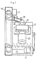
- Fig. 1 is a side elevational view partly broken away, of a washing machine of the present invention
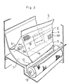
- Fig. 2 is a front elevational view thereof also partly broken away
- Fig. 3 is a perspective view of a rotary frame employed therein
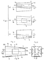
- Fig. 4 are front elevational views each showing functions of the rotary frame as observed from the side of a blasting unit
- Fig. 5 is a top plan view showing function of a modified rotary frame as observed from the side of the blasting unit
- Fig. 6 is a cross section at an end face taken along the line VI-VI in Fig. 5.
- Figs. 7 through 13 showing a second embodiment of the present invention
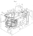
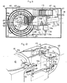
- FIG. 7 is a perspective view thereof partly broken away
- Fig. 8 is a longitudinal side sectional view thereof
- Fig. 9 is a cross section taken along the line IX-IX in Fig. 8
- Fig. 10 is a fragmentary perspective view showing an essential portion thereof
- Fig. 11 is a cross section taken along the line XI-XI in Fig. 8
- Fig. 12 is a perspective view partly broken away, of a reinforcing rubber plate employed therein
- Fig. 13 is a fragmentary side sectional view showing the state of attaching of the reinforcing rubber plate.
- Fig. 14 is a schematic perspective view showing a third embodiment of the present invention
- Fig. 15 is also a schematic perspective view showing a fourth embodiment of the present invention.
- the shots A to be employed in the present invention is produced by mixing a shot material of aluminum, a shot material formed by mixing abrasive grains in urethane resin, and another shot material only of urethane resin at a volume ratio of 2:1:1.
- the material having low hardness as compared with the conventional shot materials is selected for adoption.
- spherical shots about 3 mm in diameter are employed.
- the configuration of the shots may be as close to the spherical shape as possible to prevent injury to the object to be washed, but configurations other than the spherical shape can be adopted depending on the material of the shots, speed of discharging shots, hardness of the object to be washed, etc. Moreover, size of the shots may also be suitably selected.
- the object B to be washed in the present embodiment is an iron plate for grilled meat, on the surface of which solidified meat juice and meat itself carbonized during heating and cooking are strongly adhered.
- Figs. 1 and 2 show the washing machine for shot-cleaning the object B through employment of the shots A referred to earlier.
- the washing machine has a washing chamber 1 provided therein, at a generally central portion of which, these is laterally disposed a rotary frame body (rotary body) having a triangular cross section and arranged to be rotated with the object B to be washed held thereby.
- the rotary frame body 3 is rotatably journalled by the opposite side walls of the washing chamber 1.
- a centrifugal type blasting unit 8 (centrifugal blasting means) is mounted, so as to direct the shots A towards the rotary frame body 3 through an opening formed in said side wall.
- a bottom plate 7 for collecting the shots A as discharged is extended so as to be curved . downwardly, while in a portion of the bottom plate 7 at a position remote from said blasting unit 8, there is formed a discharge groove or ditch 10 in a cylindrical cross section for discharging the shots A out of the washing chamber 1, and this discharge ditch 10 is directed in a direction parallel to an axis 3a of the rotary frame body 3.
- the rotary frame body 3 made of a coarse wire netting is formed into a shape as in a twisted triangular column. More specifically, to each of the side faces of this rotary frame body 3, a coarse metal netting is attached from the inner side, thereby forming a holding passage 4 for slidably holding the object B to be washed for movement in a direction of the axis 3a of the rotary frame member 3.
- the holding passage 4 referred to above is twisted about the axis 3a of the rotary frame body 3 due to the twisted state of the rotary frame body 3 as described above, and as the rotary frame body 3 is rotated, a difference between a high portion and a low portion is produced at opposite ends 4a and 4b of the holding passage 4, and thus, the object B to be washed may be reciprocatingly displaced between the opposite ends 4a and 4b according to said difference in heights.
- Fig. 3 in a state as observed from the side of the blasting unit 8, when the holding passage 4 is located before the axis 3a of the rotary frame body 3 (i.e.
- the left side end portion 4b of the holding passage 4 becomes higher that the right side end portion 4a thereof, so that the object B may be laterally displaced from the right side to the left side with respect to the shot-zone.
- the holding passage 4 is located at the other side of the axis 3a of the rotary frame body 3 (i.e. at the side opposite to the blasting unit 8)
- the right side end portion 4a becomes higher than the left side end portion 4b conversely, and the object B can be laterally displaced from the left side towards the right side.
- the object B to be washed can be reciprocatingly displaced in directions crossing the shot-zone so as not to produce uneven shooting of the shots.
- a sweeper 5 formed by a rubber plate as a sweeper means is extended in a radial direction of the rotary frame body 3.
- the surface of the bottom plate 7 is formed to have a convet shape having the axis 3a of the rotary frame body 3 as a center, so that the sweepers 5 are moved towards the discharge ditch 10 while depressing the surface of the bottom plate 7 through rotation of the rotary frame body 3.
- This discharge ditch 10 is formed by a slightly finer wire netting so that the adhering substances removed from the object B can be separated from the shots A.
- a screw conveyer 13 is disposed along the discharge groove 10.
- One end of this screw conveyer 13 faces a discharge port 14 opened in the side wall of the washing chamber 1.
- a shower unit 12 provided with a nozzle 11 for sprinkling water to the discharge ditch 10 for expediting the separation of the soiling is installed along said discharge ditch 10.
- a bucket conveyer 15 is erected.
- the lower portion of the bucket conveyer 15 is connected with the screw conveyor 13 in the vicinity of the outer portion of the discharge port 14, while the upper portion of the bucket conveyer 15 is connected to a chute 16. Since this bucket conveyer 15 is provided in a posture inclined towards the side of said chute 16, in the case where buckets 15a of the bucket conveyer 15 discharge the shots A towards the chute 16, the buckets 15a are completely turned over as shown in Fig. 1 for positive discharge of the shots A.
- the chute 16 as described above is intended to transport the shots A towards the blasting unit 8, and at the upper portion in the course thereof, there is provided a detergent tank (detergent supply means) containing a soap solution (liquid detergent) so as to drop the soap solution onto the shots A passing through the chute 16. Moreover, in the course of the chute 16, a hot water supply pipe 18 is provided to supply hot water into the chute 16 at the predetermined time.
- a hopper 19 is provided below the chute 16 so as to supply the shots A or hot water transported through said chute 16 into the blasting unit 8.
- This blasting unit 8 is driven for rotation by a motor 20, and is arranged to direct the shots A or hot water towards the object B by the centrifugal force produced during the rotation.
- a motor 21 is provided to drive for rotation, the rotary frame body 3 referred to earlier.
- the object B to be washed is accommodated in the holding passage 4 of the rotary frame body 3 so as to be supported thereby. Subsequently, the rotary frame body 3 is driven for rotation, and the shots A are impinged against the rotary frame body 3 by the blasting unit 8.
- the carbonized substance strongly stuck thereto is removed by the powerful impact by the aluminum shots, while the stain uniformly spreading, for example, of oil and fat, etc. is evenly eliminated by the shots made of soft urethane resin alone and having small impact force.
- the shots made of urethane resin mixed with abrasive grains function to remove the sticky principle oil stain, and also to finish the entire surface of the object B by polishing.
- the kinds or mixing ratio of the shot material to be mixed depending on the objects to be washed and the substances adhering thereto.
- the shots made of urethane resin may be employed.
- shots applied to hard objects to be washed such as iron plates for grilled meat, etc., furuoro-rubber, silicon rubber or the like are suitable besides the urethane resin from the view point of impact-resistance, heat- resistance, hardness and specific gravity, etc., but in the case of the relatively soft object made of a synthetic resin or the like, shots prepared by polyethylene or nylon may also be employed. In any of the cases, shots should preferably have specific gravity larger than about 1.2 in the relation with respect to the liquid detergent.
- the rotary frame body 3 formed into the triangular configuration by the coarse metallic wire netting allows the shots A to readily pass from the ridge line portions between the respective objects B and B, towards the inner side of the rotary frame body 3, it is possible to cause the shots A to collide with the reverse faces of the object B located at the confronting faces with respect to the ridge line portions. Accordingly, in the washing machine of the present invention, the front and reverse faces of the object B can be simultaneously subjected to the shot-cleaning, without necessity for turning over and resetting the object B in the course of the washing work.
- the shots A are transferred to the lower portion of the backet conveyer 1-5 by the screw conveyor 13.
- the bucket conveyer 15 transports the shots A into the chute 16 disposed at the upper portion of the washing machine, and thus chute 16 supplies the shots A to the blasting unit 8 via the hopper 19.
- the shots A is applied with the soap solution dropped from the detergent tank 17 as they pass through the chute 16. This soap solution serves to clean the shots A themselves and also to wash the object B to be washed, and is not required to be collected again as stated earlier.
- the shots A are arranged to be circulated for use, with the adhering substances transferred onto said shots A being removed through two times of cleaning by water rinsing and cleaning by the soap solution on the passage, superior shot-cleaning effect of the shots can be maintained for a long period of time.
- the screw conveyer 13 and the bucket conveyer 15 are stopped to suspend discharge of the shots A, with the blasting unit 8 and the rotary frame body 3 being held in operation, and the supply of the soap solution and the sprinkling of water by the shower unit 12 are also suspended. Then, a valve of the hot water supply pipe 18 is opened to supply hot water into the chute 16. The hot water is supplied into the blasting unit 8 via the hopper 19, and is directed towards the object B by the blasting unit 8. After washing the surface of the object B, the hot water flows down onto the bottom plate 7 and is then, swept into the discharge ditch 10 by the sweepers 5.
- rinsing of the object B is effected, and simultaneously, the stain adhering to the inner face of the washing chamber 1 and the rotary frame body 3 is perfectly washed off. After the rinsing for a predetermined period of time, the object B can be taken act of the washing chamber 1 in a state approximately dried. It should be noted here that the rinsing of the object B to be washed may be effected at a place different from the present washing machine in any desired method.
- the recovery means for returning the shots A discharged from the blasting unit 8 to said blasting unit is constituted by the bottom plate 7, discharge ditch 10, screw conveyer 13, bucket conveyer 15, chute 16 and hopper 19, such recovery means may be constituted, for example, by an arrangement provided with a circulating suction pump or circulating tube pump, etc.
- the soap solution is employed as the liquid detergent
- various chemical detergents having more powerful chemical cleaning effects than the soap solution, while on the contrary, if the soiling is slight, a synthetic detergent may also be applied.
- a detergent supply means may be added to the blasting unit 8.
- the holding of the object B within the washing machine is effected by attaching the object B to the side face of the rotary frame member 3 of the triangular columnar shape made of the metallic netting
- the material and shape of such rotary frame body may be modified in any way, while the holding of the object B within the washing machine may be effected, for example, by the tumbler type which effect the shot-discharge while stirring the object to be washed, the table type, or the hunger type, etc.
- a rotary frame body 53 of a square cross section as shown in a modification of Figs. 5 and 6, with a holding passage 54 inclined with respect to the axis 53a of the rotary frame body 53 being provided at the side face of said rotary frame body 53.
- This holding passage 54 can displaceably hold the object B to be washed for movement between opposite ends 54a and 54b of said holding passage 54, in positions between the coarse metallic wire netting forming the rotary frame body 53 and a pair of parallel slide rails 54d and 54d fixed to the rotary frame body 53 from inside.
- the left side end portion 54b becomes higher than the right side end portion 54a when the holding passage 54 is at the upper side position of the frame body 53, while on the contrary, the right side end portion 54a becomes higher than the left side end portion 54b when the holding passage 54 is at the lower side position of said rotary frame body 53, and thus, since the object B can be reciprocatingly displaced in directions to cross the shot-zone following rotation of the rotary frame body 53, irregular shot application to the object B may be prevented.
- a washing chamber 102a of a circular shape there are provided a washing chamber 102a of a circular shape, and a washing tank 102 forming a shot space 102b in a rectangular configuration.
- a rotary frame body (rotary body) 103 for accommodating the object B is rotatably disposed, with its axis being approximately vertically directed.
- a motor 104 is provided to drive this rotary frame body 103 for rotation.
- a centrifugal type blasting unit (centrifugal blasting means) 105 is provided for impinging the shots A against the rotary frame body 103.
- a motor 106 is disposed to drive this blasting unit 105.
- a storage tank 114 At the side lower portion of the washing tank 102, there is provided a storage tank 114 in which the shots A discharged are to be collected.
- a bucket conveyer 107 for transferring the shots A collected in the storage tank 114 into the blasting unit 105 is provided to extend from the side lower portion to the side upper portion of the washing tank 102.
- a motor 108 is provided to drive this bucket conveyer 107.
- the rotary frame body 103 is constituted by fixing an outer frame 103a and an inner frame 103b to a bottom plate 103c in an annular shape.
- the outer frame 103a is erected generally vertically.
- the inner frame 103b is inwardly inclined at the upper portion, and defines an inlet/outlet port 103d for the object B largely opened upwardly with respect to said outer frame 103a.
- This rotary frame body 103 is rotatably supported by a rotary shaft 110 extending through the bottom portion of the washing tank 102 through a support member 109 of a cross shape fixed to the undersurface of the bottom plate 103c.
- Sweepers 111 as a sweeper means each made of a rubber plate are disposed along the support member 109 so as to be directed downward.
- the support member 109 has an inverted L-shape in cross section, and each of the sweepers III is detachably mounted on the downwardly directed side wall 109a of said support member 109 by bolts and nuts.
- the sweepers 111 depress, as the lower edges thereof, the bottom face of the cleaning chamber 102, and following rotation of the rotary frame member 103, sweep the shots A on the bottom face into a discharge port 112 to be described later.
- the rubber plate for the sweeper 111 may be replaced by a brush or the like.
- the shot port 105a of the blasting unit 105 is directed towards the rotary frame body 103 from an opening formed in the rear wall of the shot space 102b.
- the shots A are impinged against the rotary frame body 103 from the blasting unit 105.
- the direction for discharging the shots A is slightly deviated from the axis of the rotary frame body 103 towards the side to receive the rotation, so that the shots A are impinged against the object B at an angle of incidence, which should favorably be in the range of 5° - 50°.
- the amount of displacement of the outer frame 103a of the rotary frame body 103 with respect to the object B can be increased.
- the shots A can be caused to collide with the surface of the object B by being laterally moved from the side portion.
- the discharge port 112 As referred to earlier is formed to extend from the blasting unit 105 to the vicinity of the axis of the rotary frame body 103.
- the discharge port 112 is provided with a discharge chute 112a inclined towards the lower part of the bucket conveyer 107. It is to be noted here that a grating 113 is applied onto the upper open edge of the discharge port 112 so as to prevent items other than the shots A and adhering substances removed from the object B, from entering the discharge port 112.
- a punching plate 115 of a U-shape as shown in dotted lines in Fig. 8 is attached.
- the shots A are collected onto this punching plate 115.
- the diameter of the holes in the punching plate 115 is smaller than the diameter of each shot A.
- the detergent liquid is stored at a predetermined level so that the lower portion of the punching plate 115 is immersed therein.
- the adhering substances removed from the object B are separated from the shots A and settled below the punching plate 115. In this case, it is favorable if the separation of the stain is accelerated by causing the detergent liquid in the storage tank 114 to flow or by causing the punching plate 115 to vibrate.
- a drain pipe 114a for discharging the detergent liquid from the storage tank 114 and an overflow pipe 114b.
- the shots A collected on the punching plate 115 of the storage tank 114 are transferred to the blasting unit 105 at the upper part by the bucket conveyer 107.
- a supply chute 116 is connected to the blasting unit 105 for supplying the shots A to said blasting unit 105.
- a detergent tank (detergent supply means) 117 and a water supply pipe 118 are connected to the supply chute 116 so as to suitably feed the liquid detergent and water to the shots A.
- the recovery means is constituted by the washing tank 102, discharge port 112 and its discharge chute 112a, storage tank 114, bucket conveyer 107, and supply chute 116.
- a movable type safety shutter 119 is provided between the blasting unit 105 and the rotary frame body 103.
- This safety shutter 119 is pivotally supported at its one side, by the side wall of the washing tank 102 so as to be rotatable between an open position for allowing the shots A to pass therethrough and a closed position for shutting off the passing of said shots A.
- an inverted L-shaped rotary lever (movable member) 120 is rotatably provided for rotation about a pivotal axis 120a (S ⁇ O directions).
- the rotary lever 120 is depressed for movement in the direction of L by the weight of said open/close lid 121 through a depressing portion 121a thereof, and is rotated in the direction of 0.
- a coil spring (biasing means) 122 is connected between the rotary lever 120 and the outer casing 101 so as to urge in such a manner that the rotary lever 120 is rotated for restoration in the direction of S when the open/close lid 121 is opened in the direction of U.
- a rotary shaft 124 having a large diameter sprocket 123 at its upper end is rotatably provided.
- a small diameter sprocket 125 is provided, with a chain 126a being passed around these large and small diameter sprockets 123 and 125.
- a projection 124a is provided on the rotary shaft 124, and the forward end thereof and the lower end portion of said rotary lever 120 are connected by a connecting lever 126, whereby the rotation of the rotary lever 120 in the directions 0 ⁇ S is transmitted to the safety shutter 119 for rotation thereof in the O ⁇ S directions.
- the large diameter sprocket 123, rotary shaft 124 and its projection 124a, small diameter sprocket 125, chain 126a, and connecting lever 126 constitute a connecting mechanism for rotating the safety shutter 119 from the close position to the open position in association with the depression of the rotary lever 120.
- the safety shutter 119 When the open/close lid 121 is in the closed position, as the rotary lever 120 is depressed in the direction of L for rotation in the direction of O, the safety shutter 119 is rotated (in the direction O) to the open position which allows the passing of the shots A as shown by solid lines in Fig. 10, whereby the object B to be washed can be subjected to the shot washing. Meanwhile, in the case where the open/close lid 121 is not at the closed position during insertion or withdrawal of the object B or due to faulty operations, etc., the safety shutter 119 is rotated (in the direction S) to the closed position for shutting off passing of the shots A as shown by imaginary lines in Fig.
- the reinforcing rubber plate 129 is formed by covering front and rear faces of a punching sheet (a metallic core member) 130 with rubber layers 129a, 129a.
- a punching sheet a metallic core member
- rubber layers 129a synthetic rubbers such as urethane rubber, silicone rubber, etc. harmless from the viewpoint of dietary hygiene are employed, such rubber material in a liquid form is poured into a mold frame applied on the punching sheet 130 for subsequent curing or hardening.
- These rubber layers for the front and reverse faces are integrally formed through small holes 130a in the punching sheet 130.
- the thick film rubber sheet 127 referred to earlier is also formed in the similar manner as in this reinforcing rubber plate 129.
- this reinforcing rubber plate 129 onto the inner wall of the washing tank 102, the washing tank 102 and shots A are protected against import force at the collision so as to maintain durability thereof for long periods, while the noise at the collision may be reduced for suppression of such noise.
- the covering of the punching sheet 130 with the rubber layers 129a, 129a at the front and reverse faces the expansion and contraction of the rubber layer 129a in the planar direction of the punching sheet 130 may be regulated by said punching sheet 130.
- the shots A should collide against the reinforcing rubber plate 129 at very large impact force, the deterioration of the rubber layers 129a by the vibrations in the planar direction can be prevented for use for long periods.
- the reinforcing rubber plate 129 is preliminarily formed into a shape and size capable of covering only the necessary portions as shown in Fig. 12, and may be exchangeably attached to such portions through bolts and nuts. Since this reinforcing rubber plate 129 is imported with shape retaining property by the punching sheet 130, the attachment thereof may be fully effected by only fixing four corners of the plate with the bolts and nuts, whereby such portions which are subjected to the impact force by the shots A most strongly can be reinforced in an efficient manner, while detaching or attachment of the rubber plate 129 may be readily effected.
- a metallic wire netting or the line may also be used besides the punching sheet 130, and that only the front surface of the metallic core material is adopted to be covered by the rubber layer, with the reverse surface thereof exposed as it is.
- the object B to be washed is inserted, through the inlet/outlet port 103d, between the outer frame 103a and the inner frame 103b of the rotary frame 103 so as to be held thereby.
- the outer frame 103a can be omitted if stopping protrusions is provided on the bottom plate 103c of the rotary frame body 103.
- the safety shutter 119 Upon closing of the open/close lid 121, the safety shutter 119 is rotated to the opened position to allow the passing of the shots A. Subsequently, the rotary frame body 103 is rotated (counterclockwise direction in Fig. 9) to start the blasting unit 105.
- the object B is stably held on the rotary frame member 103 by its weight so as not to be displaced with respect to the rotary frame body 103, said object B is positively guided into the shot-zone following rotation of the rotary frame body 103 and passes said shot-zone at a constant speed.
- scattering in the shot-amount with respect to the object B due to deviation of the object B from the shot-zone or variation in the passing speed can be prevented, with a consequent prevention of irregular shot application.
- the shots A impinged and the stain removed from the surface of the object B by the shot A fall onto the bottom face of the washing chamber 102 for accumulation.
- the sweeper 111 in the cross shape provided on the under surface of the bottom portion of the rotary frame member 103 sweeps such shots A and the soiling into the discharge port 112.
- the shots A collected in the storage tank 114 through the discharge chute 112a are separated from the stain in said storage tank 114, and thereafter, transferred to the blasting unit 105 by the bucket conveyer 107.
- the shots A are supplied to the blasting unit 105 through the supply chute 116.
- the liquid detergent or water is swuitably supplied to the shots A. These liquid detergent and water are discharged together with the shots A, and serves for cleaning of the object B and also for the shots A themselves.
- the rotary frame body 103 for holding the object B is provided in the longitudinal direction, with its upper portion being opened upwardly to provide the inlet/outlet port 103d for the object B, while the opening 101a is provided, at the upper portion of the rotary frame body 103, in the outer casing 101, and therefore, the work for holding the object B in the watching chamber 102a or for taking out said object from the washing chamber 102a can be effected only by the upward and downward displacement of the object B, and thus, mounting and dismounting of the object B following the washing work is facilitated.
- three washing spaces are provided around the rotary body 201, while these washing spaces are arranged to be rotated intermittently through 120° among the inlet/outlet position 202 of the object B, and first and second shot positions 203 and 204.
- the rotary body 201 includes hook portions 205 to suspend the object B at each washing space, and also to rotate said object B in a horizontal plane, a circular top plate 206 on which said hook portions 205 are provided, and a rotary driving shaft 207 having said circular top plate 206 fixed at its upper end.
- the respective washing spaces are partitioned from each other by three partition walls 208 extending outwardly from the shaft 207.
- the outer casing 209 in a cylindrical configuration is formed with an inlet/outlet port 210 at an inlet/outlet position 202, and is provided with one blasting unit 211 at a first shot position 203, and two blasting units 212, and 213 at a second shot position 204.
- the blasting unit 211 at the first shot position 203 is so set as to imping the shots A against the object B from above, while at the second shot position 204, setting is so made that one balsting unit 212 directs the shot A from the side portion of the object B while the other blasting unit 213 impinges the shots A from the slantwise lower portion of the object B.
- a discharge ditch 215 is provided on the bottom plate 214 of the washing space so as to discharge the impinged shots out of the washing spaces.
- a screw conveyer 216 is provided, thereby to discharge the shots A in the discharge ditch 215 out of said discharge ditch 215.
- sweepers 217 as a sweeper means are provided to contact the bottom plate 214 under pressure, and therefore, the shots can be discharged in an efficient manner through utilization of rotation of the rotary body 201.
- a bucket conveyer 218 is erected so as to raise the shots discharged from the screw conveyer 216, and then, to supply such shots to the blasting units 211, 212 and 213.
- the shots transported upwardly by the busket conveyor 218 is supplied with the liquid detergent by the detergent supply unit 220 after passing through a stain separating unit 219, and are distributed into the respective blasting units 211, 212, and 213 through three tubes 221.
- the stain separating unit 219 is arranged to screen off only the soiling substances removed from the object B by causing to vibrate, a metallic wire netting with a mesh smaller than the diameter of the shots. It is to be noted here that in the present embodiment, the bottom plate 214, discharge ditch 215 and bucket conveyer 218 constitute the recovery means.
- the insertion and withdrawal of the object B, and the shot-cleaning thereof may be effected in a parallel relation.
- the object B is rotated with respect to the respective blasts 211, 212 and 213, and the shots are impinged from different angles at the first shot position 203 and the second shot position 204, the objects to be washed having complicated concave and convex shapes such as bottle cases and baskets, etc. may be efficiently washed. It is to be noted here that, in this embodiment, depending on the sizes and shapes, etc.
- the hooks for suspending the items to be painted used for painting process and the like may be arranged to be directly suspended by the hook portion 205, or to be suspended by said hook portion after being accommodated 111 holding cage of a metallic wire netting, etc. not hindering the passing of the shots.
- Fig. 15 shows a fourth embodiment according to the present invention which is capable of shot-washing objects to be washed such as tableware and the like, in a large amount and continuously.
- a chain 351 is passed around a pair of left and right sprockets 350, 350, and a plurality of cages 352 for accommodating the objects to be washed are suspended from said chain 351.
- An inlet/outlet port 354 for the objects to be washed is formed at the front wall of an outer casing 353, while a set of upper and lower shot units 355 and 356 are disposed at the right inner side of the outer casing 353.
- the upper blasting unit 355 is adapted to subject the object in the cage 352 to the shot-washing from the slantwise upper portion.
- the lower blasting unit 356 is arranged to subject the object to the shot-cleaning from the slantwise lower portion.
- the respective blasting units 355 and 356 are additionally provided with detergent supply units (detergent supply means) 357 and 358 for supplying the liquid detergent to the shots.
- a shower unit 359 is provided at the left inner portion in the outer casing 353 so as to spray water or hot water to the object after the shot-cleaning for rinsing. It is to be noted that, in the case where water is sprayed by the shower unit 359, a heated air blower unit or the like may be disposed at the left side of the shower unit 359 so as to evaporate the water component of the object B by the hot.air of the blower unit.
- a shielding wall 360 is erected between the blasting units 355 and 356 and the shower unit 359, and also the inlet/outlet port 354, thereby to prevent the shots and hot water from scattering out of this inlet/outlet port 354.
- a bottom plate 361 in a funnel shape is provided so as to collect the impinged shots for guiding into a suction pump 362.
- the suction pump 362 supplies the collected shots to the respective blasting units 355 and 356 through respective transport tubes 363 and 364.
- the recovery means for collecting the impinged shots and returning them to said blasting units 355 and 356 is constituted by the bottom plate 361, suction pump 362, and transport tubes 363 and 364:
- shots formed into a sponge-like state by exponding a synthetic resin such as urethane or the like may be impregnated with liquid detergent for impinging upon objects to be washed, whereby the liquid detergent may be applied to the object without a loss, while, by the marked reduction of the hardness of the shots, injury to the surface of a particularly soft object can be advantageously avoided.
Landscapes
- Engineering & Computer Science (AREA)
- Mechanical Engineering (AREA)
- Cleaning By Liquid Or Steam (AREA)
- Nozzles For Electric Vacuum Cleaners (AREA)
Abstract
Machine à laver dans laquelle un détergent liquide est appliqué à une grenaille (A) de faible dureté relative et qui est ensuite envoyée sur l'objet à laver (B) par l'utilisation de moyens de projection centrifuge (8; 105). Ensuite ladite grenaille est ramenée aux moyens de projection (8; 105), ladite machine comportant un moyen de récupération (7, 10, 13, 15, 16, 19; 102, 107, 112, 112a), un moyen d'alimentation de détergent (17, 117), un registre de sécurité pour empêcher l'utilisation de grenaille inappropriée (119), une plaque en caoutchouc anti-vibrations et d'isolation phonique (129), une raclette pour dégager la grenaille (15; 111) et un corps rotatif qui maintient les objets à laver, pour changer de zone de grenaillage (3; 103) etc. La machine à laver est destinée aux objets comportant un niveau élevé de salissures et qui doivent être lavés dans leur intégralité, comme par exemple une plaque de fer utilisée pour rôtir de la viande, les couverts, un sac à commissions, un casier de bouteilles portatif, un crochet pour suspendre les objets peints, etc.
Applications Claiming Priority (4)
| Application Number | Priority Date | Filing Date | Title |
|---|---|---|---|
| JP518/85 | 1986-04-07 | ||
| JP5188586U JPH0428551Y2 (fr) | 1986-04-07 | 1986-04-07 | |
| JP61302619A JPS63153038A (ja) | 1986-12-17 | 1986-12-17 | 洗浄機 |
| JP302619/86 | 1986-12-17 |
Publications (2)
| Publication Number | Publication Date |
|---|---|
| EP0263883A1 true EP0263883A1 (fr) | 1988-04-20 |
| EP0263883A4 EP0263883A4 (fr) | 1990-01-08 |
Family
ID=26392473
Family Applications (1)
| Application Number | Title | Priority Date | Filing Date |
|---|---|---|---|
| EP19870902705 Ceased EP0263883A4 (fr) | 1986-04-07 | 1987-04-06 | Machine a laver. |
Country Status (4)
| Country | Link |
|---|---|
| US (1) | US4959930A (fr) |
| EP (1) | EP0263883A4 (fr) |
| KR (1) | KR930006788B1 (fr) |
| WO (1) | WO1987006172A1 (fr) |
Cited By (3)
| Publication number | Priority date | Publication date | Assignee | Title |
|---|---|---|---|---|
| DE4106831C1 (fr) * | 1991-03-04 | 1992-08-27 | Friedbert 7519 Zaisenhausen De Doll | |
| EP1145802A1 (fr) * | 2000-03-31 | 2001-10-17 | Sumitomo Special Metals Co., Ltd. | Appareil de grenaillage |
| CN108161771A (zh) * | 2018-02-26 | 2018-06-15 | 青岛金泰瑞金属制品有限公司 | 吊钩式抛丸机 |
Families Citing this family (6)
| Publication number | Priority date | Publication date | Assignee | Title |
|---|---|---|---|---|
| SE9201117D0 (sv) * | 1992-04-08 | 1992-04-08 | Svemo Mekaniska Ab | Anordning foer diskmaskiner |
| JPH08509782A (ja) * | 1993-03-11 | 1996-10-15 | ワトソン、ダナ・エル | 廃棄物の再生処理方法およびそのための装置 |
| US5637029A (en) * | 1993-11-22 | 1997-06-10 | Lehane; William B. | Method and apparatus for shot blasting materials |
| GB201002245D0 (en) * | 2010-02-10 | 2010-03-31 | Xeros Ltd | Improved cleaning apparatus and method |
| GB201317558D0 (en) * | 2013-10-03 | 2013-11-20 | Xeros Ltd | Cleaning apparatus |
| CN112120626A (zh) * | 2019-06-24 | 2020-12-25 | 苏州亿伟德机电科技有限公司 | 一种清洗器 |
Family Cites Families (24)
| Publication number | Priority date | Publication date | Assignee | Title |
|---|---|---|---|---|
| US919417A (en) * | 1908-04-03 | 1909-04-27 | Samuel C Carroll | Cleaning and polishing apparatus. |
| US1522159A (en) * | 1921-06-30 | 1925-01-06 | American Radiator Co | Sand-blast apparatus |
| US1713965A (en) * | 1927-07-14 | 1929-05-21 | Pangborn Corp | Sand-blast table |
| US2304071A (en) * | 1938-11-25 | 1942-12-08 | Minnesota Mining & Mfg | Sandblast booth |
| US2429742A (en) * | 1944-10-12 | 1947-10-28 | American Wheelabrator & Equipm | Treating surfaces of workpieces with abrasives |
| DE876666C (de) * | 1945-01-26 | 1953-05-18 | Johnson & Borsell Ab | Maschine zum Herrichten von lithographischen Druckplatten |
| US2632980A (en) * | 1949-07-08 | 1953-03-31 | Ransohoff Inc N | Method and apparatus for wet grit blasting |
| DE877424C (de) * | 1950-03-21 | 1953-05-26 | Johnson & Borsell Ab | Spannschiene |
| US2629207A (en) * | 1950-10-09 | 1953-02-24 | Pangborn Corp | Plate blasting machine |
| US2996846A (en) * | 1959-07-29 | 1961-08-22 | Bell Intercontrinental Corp | Method and means for deflashing or trimming molded rubber parts |
| FR1327624A (fr) * | 1962-07-03 | 1963-05-17 | Procédé et machine pour laver la vaisselle | |
| GB1099701A (en) * | 1964-01-07 | 1968-01-17 | Howard Duncan Goulding | Improvements in or relating to cleaning |
| FR1394192A (fr) * | 1964-02-18 | 1965-04-02 | Perfectionnement aux machines à laver la vaisselle | |
| US3309818A (en) * | 1964-06-05 | 1967-03-21 | Brown Co D S | Blast cleaning machines and removable panels therefor |
| US3323159A (en) * | 1964-12-10 | 1967-06-06 | Gen Motors Corp | Dishwasher with particle reclaiming |
| DE1477964B1 (de) * | 1965-03-23 | 1969-09-04 | Badische Maschf Gmbh | Schleuderstrahlmaschine zum chargenweisen Behandeln von Werkstuecken |
| US3395412A (en) * | 1966-09-12 | 1968-08-06 | Louis A. Derwin | Washing apparatus |
| CH458646A (de) * | 1966-10-14 | 1968-06-30 | Albers Schoenberg Ernst Dr | Verfahren zum maschinellen Waschen von Geschirr mit einer Waschflüssigkeit |
| US3425078A (en) * | 1966-10-19 | 1969-02-04 | Francisco F Lazaga | Washing machine to use impact of solid materials and solid recollecting ejector |
| DE2129737A1 (de) * | 1971-06-15 | 1972-12-21 | Berger Maschf Gmbh | Strahlmaschine zum wahlweisen Putzen von Werkstuecken mittels Schleuderrad oder Freistrahlgeraet |
| JPS5523799Y2 (fr) * | 1976-07-06 | 1980-06-06 | ||
| DE3070945D1 (en) * | 1979-04-02 | 1985-09-12 | Carl Goran Christer Mosell | Cleaning machine |
| US4524550A (en) * | 1982-11-30 | 1985-06-25 | Air Products And Chemicals, Inc. | Discharge of blasting media from a treating chamber |
| US4505077A (en) * | 1983-03-16 | 1985-03-19 | Empire Abrasive Equipment Corporation | Cabinet door interlock |
-
1987
- 1987-04-06 KR KR1019870701151A patent/KR930006788B1/ko not_active Expired - Fee Related
- 1987-04-06 US US07/143,853 patent/US4959930A/en not_active Expired - Fee Related
- 1987-04-06 WO PCT/JP1987/000213 patent/WO1987006172A1/fr not_active Ceased
- 1987-04-06 EP EP19870902705 patent/EP0263883A4/fr not_active Ceased
Cited By (5)
| Publication number | Priority date | Publication date | Assignee | Title |
|---|---|---|---|---|
| DE4106831C1 (fr) * | 1991-03-04 | 1992-08-27 | Friedbert 7519 Zaisenhausen De Doll | |
| EP1145802A1 (fr) * | 2000-03-31 | 2001-10-17 | Sumitomo Special Metals Co., Ltd. | Appareil de grenaillage |
| US6743082B2 (en) | 2000-03-31 | 2004-06-01 | Sumitomo Special Metals Co., Ltd. | Blasting apparatus |
| US7086934B2 (en) | 2000-03-31 | 2006-08-08 | Neomax Co., Ltd. | Method for treating surfaces of rare earth metal-based permanent magnets |
| CN108161771A (zh) * | 2018-02-26 | 2018-06-15 | 青岛金泰瑞金属制品有限公司 | 吊钩式抛丸机 |
Also Published As
| Publication number | Publication date |
|---|---|
| WO1987006172A1 (fr) | 1987-10-22 |
| KR880701155A (ko) | 1988-07-25 |
| KR930006788B1 (ko) | 1993-07-23 |
| US4959930A (en) | 1990-10-02 |
| EP0263883A4 (fr) | 1990-01-08 |
Similar Documents
| Publication | Publication Date | Title |
|---|---|---|
| US5398708A (en) | Parts cleaning machine | |
| US20150251117A1 (en) | Apparatus and system for cleaning a filter | |
| US6887135B2 (en) | Ball finishing apparatus and process | |
| KR20100033709A (ko) | 벨트 컨베이어 청소장치 | |
| US4959930A (en) | Washing machine | |
| US4209344A (en) | Delabeling hollow articles | |
| JPH07507228A (ja) | 長形物を洗浄する方法及び装置 | |
| JPH01317855A (ja) | 車輪洗浄装置 | |
| US4765020A (en) | Silverware washing machine | |
| WO2022194706A1 (fr) | Alimentation en liquide d'au moins une zone d'une surface à nettoyer | |
| JP4711047B2 (ja) | 野菜等の洗浄装置 | |
| WO1999016026A1 (fr) | Machine de lavage pour jetons de jeu | |
| JPH11277009A (ja) | 超音波洗浄機および超音波洗浄システム | |
| US5161558A (en) | Vibrating apparatus for cleaning floatable and light weight objects | |
| JPH11138440A (ja) | ブラスト式洗浄装置 | |
| JP3630509B2 (ja) | 回転ドラムの洗浄・乾燥装置 | |
| JP2021151203A (ja) | 食品洗浄装置 | |
| GB2283686A (en) | Cleaning play balls | |
| KR102676685B1 (ko) | 불판 자동 세척기 | |
| JP2502901B2 (ja) | ボ―ル洗浄装置 | |
| JP3469174B2 (ja) | 皮剥き装置 | |
| JPH049981Y2 (fr) | ||
| JPH06105791A (ja) | 洗浄装置 | |
| JPH0690886A (ja) | 洗浄設備 | |
| JP2003199546A (ja) | 皮剥き装置 |
Legal Events
| Date | Code | Title | Description |
|---|---|---|---|
| PUAI | Public reference made under article 153(3) epc to a published international application that has entered the european phase |
Free format text: ORIGINAL CODE: 0009012 |
|
| AK | Designated contracting states |
Kind code of ref document: A1 Designated state(s): DE FR GB IT |
|
| 17P | Request for examination filed |
Effective date: 19880415 |
|
| A4 | Supplementary search report drawn up and despatched |
Effective date: 19900108 |
|
| 17Q | First examination report despatched |
Effective date: 19910722 |
|
| STAA | Information on the status of an ep patent application or granted ep patent |
Free format text: STATUS: THE APPLICATION HAS BEEN REFUSED |
|
| 18R | Application refused |
Effective date: 19930916 |