EP0264782A2 - Dispositif de commande pour son musical utilisant un capteur - Google Patents
Dispositif de commande pour son musical utilisant un capteur Download PDFInfo
- Publication number
- EP0264782A2 EP0264782A2 EP87114944A EP87114944A EP0264782A2 EP 0264782 A2 EP0264782 A2 EP 0264782A2 EP 87114944 A EP87114944 A EP 87114944A EP 87114944 A EP87114944 A EP 87114944A EP 0264782 A2 EP0264782 A2 EP 0264782A2
- Authority
- EP
- European Patent Office
- Prior art keywords
- musical tone
- signal
- control apparatus
- tone control
- detecting
- Prior art date
- Legal status (The legal status is an assumption and is not a legal conclusion. Google has not performed a legal analysis and makes no representation as to the accuracy of the status listed.)
- Granted
Links
Images












Classifications
-
- G—PHYSICS
- G06—COMPUTING OR CALCULATING; COUNTING
- G06F—ELECTRIC DIGITAL DATA PROCESSING
- G06F3/00—Input arrangements for transferring data to be processed into a form capable of being handled by the computer; Output arrangements for transferring data from processing unit to output unit, e.g. interface arrangements
- G06F3/01—Input arrangements or combined input and output arrangements for interaction between user and computer
- G06F3/011—Arrangements for interaction with the human body, e.g. for user immersion in virtual reality
- G06F3/014—Hand-worn input/output arrangements, e.g. data gloves
-
- G—PHYSICS
- G10—MUSICAL INSTRUMENTS; ACOUSTICS
- G10H—ELECTROPHONIC MUSICAL INSTRUMENTS; INSTRUMENTS IN WHICH THE TONES ARE GENERATED BY ELECTROMECHANICAL MEANS OR ELECTRONIC GENERATORS, OR IN WHICH THE TONES ARE SYNTHESISED FROM A DATA STORE
- G10H1/00—Details of electrophonic musical instruments
-
- G—PHYSICS
- G10—MUSICAL INSTRUMENTS; ACOUSTICS
- G10H—ELECTROPHONIC MUSICAL INSTRUMENTS; INSTRUMENTS IN WHICH THE TONES ARE GENERATED BY ELECTROMECHANICAL MEANS OR ELECTRONIC GENERATORS, OR IN WHICH THE TONES ARE SYNTHESISED FROM A DATA STORE
- G10H1/00—Details of electrophonic musical instruments
- G10H1/32—Constructional details
-
- G—PHYSICS
- G10—MUSICAL INSTRUMENTS; ACOUSTICS
- G10H—ELECTROPHONIC MUSICAL INSTRUMENTS; INSTRUMENTS IN WHICH THE TONES ARE GENERATED BY ELECTROMECHANICAL MEANS OR ELECTRONIC GENERATORS, OR IN WHICH THE TONES ARE SYNTHESISED FROM A DATA STORE
- G10H2220/00—Input/output interfacing specifically adapted for electrophonic musical tools or instruments
- G10H2220/155—User input interfaces for electrophonic musical instruments
- G10H2220/321—Garment sensors, i.e. musical control means with trigger surfaces or joint angle sensors, worn as a garment by the player, e.g. bracelet, intelligent clothing
- G10H2220/326—Control glove or other hand or palm-attached control device
-
- G—PHYSICS
- G10—MUSICAL INSTRUMENTS; ACOUSTICS
- G10H—ELECTROPHONIC MUSICAL INSTRUMENTS; INSTRUMENTS IN WHICH THE TONES ARE GENERATED BY ELECTROMECHANICAL MEANS OR ELECTRONIC GENERATORS, OR IN WHICH THE TONES ARE SYNTHESISED FROM A DATA STORE
- G10H2220/00—Input/output interfacing specifically adapted for electrophonic musical tools or instruments
- G10H2220/155—User input interfaces for electrophonic musical instruments
- G10H2220/401—3D sensing, i.e. three-dimensional (x, y, z) position or movement sensing
-
- G—PHYSICS
- G10—MUSICAL INSTRUMENTS; ACOUSTICS
- G10H—ELECTROPHONIC MUSICAL INSTRUMENTS; INSTRUMENTS IN WHICH THE TONES ARE GENERATED BY ELECTROMECHANICAL MEANS OR ELECTRONIC GENERATORS, OR IN WHICH THE TONES ARE SYNTHESISED FROM A DATA STORE
- G10H2240/00—Data organisation or data communication aspects, specifically adapted for electrophonic musical tools or instruments
- G10H2240/171—Transmission of musical instrument data, control or status information; Transmission, remote access or control of music data for electrophonic musical instruments
- G10H2240/201—Physical layer or hardware aspects of transmission to or from an electrophonic musical instrument, e.g. voltage levels, bit streams, code words or symbols over a physical link connecting network nodes or instruments
- G10H2240/211—Wireless transmission, e.g. of music parameters or control data by radio, infrared or ultrasound
Definitions
- the present invention generally relates to a musical tone control apparatus using a detector, and more particularly to a musical tone control apparatus which controls a musical tone in response to a movement of a player and the like detected by a detector.
- musical tones are generated by playing a natural musical instrument (such as a violin, a piano, an organ and a bass drum) and an electronic musical instrument and the like.
- a tone pitch and a tone color of the generating musical tone is controlled by touching or depressing keys, strings or pedals by use of hands or feet of the player.
- a musical tone control apparatus comprising: (a) detector means for detecting a movement itself of an object; (b) musical tone control means for controlling a musical tone signal based on a detecting result of the detector means; and (c) musical tone generating means for generating a musical tone corresponding to the musical tone signal.
- a musical tone control apparatus comprising: (a) detecting means for detecting a swing movement itself of an object to be detected; and (b) means for outputting musical tone control data which control a musical tone signal based on a detecting result of the detecting means.
- a musical tone control apparatus comprising: (a) detecting means for detecting acceleration of an object to be detected; and (b) means for outputting musical tone control data which control a musical tone signal based on a detecting result of the detecting means.
- a musical tone control apparatus comprising: (a) acceleration sensor means being connected to the predetermined part of the human body; (b) first detecting means for outputting a first detection signal when an output level of the acceleration sensor means becomes higher than a predetermined first level; (c) second detecting means for outputting a second detection signal when a level of a higher harmonic component included in the output signal of the acceleration sensor means becomes higher than a predetermined second level; (d) hold means for holding the higher harmonic component level when both of the first and second detection signals are outputted respectively from the first and second detecting means; and (e) first means for generating first musical tone control data which control a musical tone signal based on a detecting result of the first detecting means.
- a musical tone control apparatus comprising: (a) acceleration sensor means being mounted at the predetermined part of the human body; (b) first detecting means for outputting a first detection signal the level of which becomes a predetermined level while an output level of the acceleration sensor means becomes higher than a level of a first reference signal; (c) amplifier means for amplifying a higher harmonic component included within the output signal of the acceleration sensor; (d) second detecting means for outputting a second detection signal the level of which becomes a predetermined level while the output level of the amplifier means becomes higher than a level of a second reference signal; (e) interrupt signal generating means for generating an interrupt signal representing that both levels of the first and second detection signals become identical to the predetermined level; (f) hold means for holding a peak value of the higher harmonic component in response to a timing of the second detection signal; (g) analog-to-digital converter means for converting the peak value of the higher harmonic component into digital data representing the intensity of impulse; and (h) central processing means
- a musical tone generating apparatus comprising: (a) acceleration sensor means being mounted at the predetermined part of the human body; (b) first detecting means for outputting a first detection signal the level of which becomes a predetermined level while an output level of the acceleration sensor means becomes higher than a level of a first reference signal; (c) amplifier means for amplifying a higher harmonic component included within the output signal of the acceleration sensor; (d) second detecting means for outputting a second detection signal the level of which becomes a predetermined level while the output level of the amplifier means becomes higher than a level of a second reference signal; (e) interrupt signal generating means for generating an interrupt signal representing that both levels of the first and second detection signals become identical to the predetermined level; (f) hold means for holding a peak value of the higher harmonic component in response to a timing of the second detection signal; (g) analog-to-digital converter means for converting the peak value of the higher harmonic component into digital data representing the intensity of impulse; (h) central processing means
- a musical tone control apparatus comprising: (a) a first integration circuit for integrating an acceleration signal outputted from an acceleration sensor which detects an acceleration of an object so as to convert the acceleration signal into a speed signal representing a moving speed of the object; (b) a second integration circuit for integrating the speed signal so as to convert the speed signal into a distance signal representing a moving distance of the object; (c) control means for controlling integration actions of the first and second integration circuit based on a level of the acceleration signal in a predetermined period; and (d) generating means for generating a musical tone signal in accordance with the distance signal.
- a musical tone control apparatus comprising: (a) a first integration circuit for integrating an acceleration signal outputted from an acceleration sensor which detects an acceleration of the object so as to convert the acceleration signal into a speed signal representing a moving speed of the object; (b) a second integration circuit for integrating the speed signal so as to convert the speed signal into a distance signal representing a moving distance of the object; and (c) control means for controlling integration actions of the first and second integration circuit based on a level of the acceleration signal in an acceleration increasing period when the acceleration of the object is increasing, the control means outputting an interrupt signal at a timing when the acceleration increasing period is ended; (d) a central processing unit supplied with the interrupt signal; (e) analog-to-digital converter means for converting the speed signal and the distance signal into respective digital data at a timing of the interrupt signal under a control of the central processing unit; (f) register means for storing the digital data therein, the central processing unit reading out the digital data stored in the register means so as to output the
- a musical tone control apparatus comprising: (a) detecting means for detecting characteristics of a tone which is generated based on an action of a player; and (b) means for generating musical tone control data based on a detecting result of the detecting means.
- a musical tone control apparatus comprising: (a) detecting means for detecting a bending or revolving movement of a joint of a player; and (b) means for generating musical tone control data which control a musical tone signal based on a detecting result of the detecting means.
- a musical tone control apparatus comprising: (a) detecting means for detecting a bending angle or a revolving angle of a predetermined portion of a player; and (b) means for generating musical tone control data which control a musical tone signal based on a detecting result of the detecting means.
- a musical tone control apparatus comprising: (a) angle detecting means for detecting an angle formed between an object and a reference plane and generating an angle signal representative of the detected angle; and (b) means for generating musical tone control data which control an external musical tone generating apparatus based on the angle signal.
- a musical tone control apparatus comprising: (a) detecting means for detecting a position of at least a predetermined portion of a player's body with respect to a reference point; and (b) generating means for generating musical tone control data which control the musical tone based on a detecting result of the detecting means, the musical tone control data being supplied to the musical tone generating apparatus.
- a musical tone control apparatus comprising: (a) detecting means mounted on in the vicinity of a joint portion of a player, the detecting means detecting an angle of the joint portion; (b) means for detecting a revolving angular velocity of the joint portion based on a variation of the angle detected by the detecting means in lapse of time; and (c) generating means for generating a musical tone signal in accordance with the distance signal.
- a musical tone control apparatus comprising: (a) a hollow case; (b) a plurality of contacts arranged within the inside of the hollow case; (c) conductive fluid enclosed within the hollow case, the conductive fluid moving or flowing in response to an inclination of the hollow case so as to electrically connect between two contacts among the plural contacts, the hollow case generating an angle signal representative of the inclination of the hollow case in response to connected contacts; and (d) generating means for generating musical tone control data which control a musical tone to be generated based on the angle signal.
- the present invention relates to a musical tone control apparatus which controls the musical tones based on the movement of the object such as a player's hand and the like.
- This movement of the player's hand such as a moving speed, a moving force or a moving angle of the object, must be detected by a detector.
- the detector according to the present invention can be classified into an impulse detector, a motion detector, an angular velocity detector and an angle sensor. Hence, description will be given with respect to these detectors and the sensor sequentially.
- Fig. 1 shows a circuit constitution of an embodiment of the musical tone generating apparatus employing the impulse detector according to the present invention.
- 11 designates an acceleration sensor which has a vibrator made of an organic material or an inorganic material having piezoelectric characteristics.
- a piezo-plastic and the like are used.
- inorganic material a crystal, a Rochelle salt, a barium titanate and the like are used.
- the piezoplastic is used as an organic vibrator, the circumference of which is fixed so that the vibrator has a diaphragm structure.
- the above-mentioned acceleration sensor 11 converts the acceleration into the voltage signal, hence, the acceleration sensor 11 generates and outputs an output voltage V a as shown in Fig. 2(a).
- 12 in Fig. 1 designates a resistor having a resistance of R1 (Ohm), and one terminal of the resistor 12 is connected to an output terminal of the acceleration sensor 11.
- 13 designates a capacitor having a capacitance of C1 (F), another terminal of the resistor 12 is grounded via the capacitor 13.
- These resistor 12 and capacitor 13 constitute a lowpass filter 14 having a time constant of R1C1 (seconds).
- the connection point between the resistor 12 and the capacitor 13 is connected to a non-inverting input terminal (+) of a comparator 15.
- a resistor 16 having a resistance of R2 (Ohm) is connected to the output terminal of the acceleration sensor 11, and another terminal of the resistor 16 is grounded via a capacitor 17 having a capacitance of C2.
- These resistor 16 and capacitor 17 constitute a lowpass filter 18 having a time constant of R2C2 (seconds).
- the time constant R2C2 is set approximately ten times of the time constant R1C1 More concretely, the time constant R2C2 is set equal to 0.5 milli-second and the time constant R1C1 is set equal to 50 micro-seconds.
- connection point between the resistor 16 and the capacitor 17 is connected to an anode of a diode 19, and an inverting input terminal (-) of the comparator 15 is connected to a cathode of the diode 19. Similar to the diode 19, a cathode of a diode 20 is connected to the inverting input terminal of the comparator 15. One terminal of a resistor 21 is connected to an anode of the diode 20, hence, the diode 20 and the resistor 21 constitutes a serial circuit which supplies a reference voltage V r1 to the inverting input terminal of the comparator 15.
- One terminal of a capacitor 24 is connected to the output terminal of the acceleration sensor 11, and another terminal of the capacitor 24 is connected to an input terminal of an amplifier 25 which is grounded via a resistor 26.
- the resistor 26 and the capacitor 24 constitute a highpass filter 27.
- One terminal of a resistor 28 is connected to the output terminal of the amplifier 25, and another terminal of the resistor 28 is connected to a non-inverting input terminal (+) of a comparator 29.
- one terminal of a resistor 30 having a resistance of R3 (which is provided at an inverting input terminal (-) side of the comparator 29) is connected to the output terminal of the amplifier 25.
- Another terminal of the resistor 30 is connected to an anode of a diode 31 and is also grounded via a capacitor 32 having a capacitance of C3
- the resistor 30 and the capacitor 32 constitute a lowpass filter 32 having a time constant of R3C3.
- a cathode of diode 31 is connected to the inverting input terminal of the comparator 29.
- a cathode of diode 34 is connected to the inverting input terminal of the comparator 29, whereas an anode of diode 34 is connected to one terminal of a resistor 35.
- the diode 34 and the resistor 35 constitute a serial circuit which supplies a reference voltage V r2 to the inverting input terminal of the comparator 29.
- 22 designates an AND gate having two input terminals, one of which is connected to the output terminal of the comparator 15.
- a data input terminal D of a D flip-flop 23 is connected to the output terminal of the comparator 15, and a clock input terminal of the D flip-flop 23 is connected to the output terminal of the comparator 29.
- the D flip-flop 23 has a reset terminal R, and an output terminal Q of the D flip-flop 23 is connected to another input terminal of the AND gate 22.
- This D flip-flop 23 stores data supplied to the data input terminal D thereof at a leading edge timing of a pulse signal supplied to the clock input terminal thereof.
- an input terminal of an analog switch 36 is connected to the output terminal of the amplifier 25, and a gate terminal of the analog switch 36 is connected to the output terminal of the comparator 29.
- an output terminal of the analog switch 36 is connected to an input terminal of an analog-to-digital (A/D) converter 38 which is grounded via a capacitor 37.
- This capacitor 37 is provided for holding a peak value of an analog signal supplied to the A/D converter 38 via the analog switch 36.
- a central processing unit (CPU) 39 is connected to the output terminal of the AND gate 22, the reset terminal R of the D flip-flop 23 and a digital output terminal of the A/D converter 38.
- the CPU 39 outputs data D p to a musical tone signal generating circuit 41 wherein a musical tone signal A p corresponding to the data D p is generated.
- the musical tone signal A p is supplied to a speaker 43 wherein a musical tone corresponding to the musical tone signal A p is generated.
- the acceleration sensor 11 is mounted on a part of the player, i.e., a palm of the player's hand, for example.
- This acceleration sensor 11 generates the voltage signal V a shown in Fig. 2(a) at a timing when the player claps his hands.
- Such signal V a is inputted to the non-inverting input terminal of the comparator 15 via the lowpass filter 14, and the signal V a is also inputted to the inverting input terminal of the comparator 15 via the lowpass filter 18.
- the non-inverting input terminal of the comparator 15 is supplied with a signal V b b (shown in Fig.
- the inverting input terminal of the comparator 15 is supplied with a signal V c (shown in Fig. 2(b)) which is obtained by delaying the signal V a by a delay time corresponding to the time constant R2C2 (sec) of the lowpass filter 18.
- the diode 19 is inserted between the lowpass filter 18 and the inverting input terminal of the comparator 15.
- This diode 19 is subject to a bias state in backward direction when the level of the output signal of the lowpass filter 18 is lower than that of the reference voltage V r1 , whereby the diode 19 is turned off and the reference voltage V r1 is supplied to the inverting input terminal of the comparator 15.
- the diode 19 is subject to a bias state in forward direction when the level of the output signal of the lowpass filter 18 is higher than that of the reference voltage V r1 , whereby the diode 19 is turned on and the output signal of the lowpass filter 18 is supplied to the inverting input terminal of the comparator 15.
- the time constant R1C1 is set smaller than the time constant R2C2, hence, the phase of the signal V c is delayed behind that of the signal V b .
- the comparator 15 outputs a pulse signal V d (shown in Fig. 2(c)), the level of which rises up to a high (H) level while the level of the signal V b is higher than that of the signal V c .
- the voltage signal V a outputted from the acceleration sensor 11 is also supplied to the highpass filter 27 wherein a higher harmonic component signal is extracted from the signal V a .
- the level of such extracted signal is amplified in the amplifier 25 so that the amplifier 25 outputs a signal V e as shown in Fig. 2(d).
- the signal V e is supplied to the non-inverting input terminal of the comparator 29 via the resistor 28.
- the signal V e is also supplied to the lowpass filter 33 wherein the signal V e is subject to a time delay (or an integration operation).
- the diode 31 is inserted between the lowpass filter 33 and the inverting input terminal of the comparator 29, and the reference voltage V r2 is supplied to the inverting input terminal of the comparator 29.
- the reference voltage V r2 must be always supplied to the inverting input terminal of the comparator 29 while the level of the output signal of the lowpass filter 33 is lower than that of the reference voltage V r2 .
- the output signal of the lowpass filter 33 is supplied to the inverting input terminal of the comparator 29 while the level of the output signal of the lowpass filter 33 is higher than that of the reference voltage V r2 .
- a signal V f shown in Fig. 2(d) is inputted into the inverting input terminal of the comparator 29.
- the comparator 29 outputs a pulse signal V g having the H level (as shown in Fig. 2(e)) while the level of the signal V e is higher than that of the signal V f
- the above-mentioned signal V g is supplied to the clock input terminal of the D flip-flop 23 as the clock signal. Since the signal V d (shown in Fig. 2(c)) is supplied to the data input terminal D of the D flip-flop 23, the D flip-flop 23 stores the signal V d at a leading edge timing of the signal V g and outputs an output signal V h (shown in Fig. 2(f)) via an output terminal Q thereof. The logical product of the signals V h and V d is obtained in the AND gate 22. Hence, the AND gate 22 outputs a signal V i (shown in Fig. 2(g)). This signal V i is supplied to the CPU 39 as an interrupt signal.
- Fig. 2(h) shows a waveform of a voltage signal V j held by the capacitor 37.
- Such voltage signal V j is converted into the corresponding digital data D d in the A/D converter 38, and such digital data D d are supplied to the CPU 39.
- the interrupt signal V i is supplied to the CPU 39 wherein a signal RACK (shown in Fig. 2(i)) is generated and outputted to the reset terminal R of the D flip-flop 23, whereby the D flip-flop 23 is reset. Thereafter, the CPU 39 stores the digital data D d outputted from the A/D converter 38. Next, the CPU 39 converts the stored digital data D d into tone pitch data D p designating the tone pitch of the musical tone, and the tone pitch data D p are supplied to the musical tone signal generating circuit 41.
- the musical tone signal generating circuit 41 generates the musical tone signal designating the tone pitch corresponding to the tone pitch data D p .
- This musical tone signal is outputted to the speaker 43, whereby the speaker 43 generates the musical tone having the tone pitch corresponding to the intensity of the impulse given to the acceleration sensor 11 mounted on the player′s hand.
- the acceleration sensor 11 can be fixed at a predetermined part of the player. According to the constitution of the present embodiment, it is possible to generate a musical tone having a tone pitch corresponding to an intensity of hand clapping, an intensity of step shock occurred between a floor and the feet of the player.
- the present embodiment generates the musical tone having the tone pitch corresponding to the intensity of impulse detected by the acceleration sensor 11.
- the impulse detector according to the present invention is not limited to the present embodiment.
- the impulse detector so that the tone colors of the musical tones are controlled independently based on the signal V b (shown in Fig. 2(b)) and the signal V e (shown in Fig. 2(d)).
- a musical tone of the bass drum can be controlled by the signal V b
- another musical tone of a cymbal can be controlled by the signal V e .
- two kinds of musical tones can be controlled by use of only one detector (i.e., only one acceleration sensor 11).
- the impulse detector according to the present invention can eliminate detecting errors caused by touching noise and the like, and the present impulse detector can detect the intensity of impulse with accuracy.
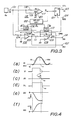
- Fig. 3 is a circuit diagram showing an embodiment of a motion detector according to the present invention. More specifically, the circuit shown in Fig. 3 generates signals corresponding to a speed and a moving distance of an object to be detected by integrating an output signal of an acceleration sensor.
- 101 designates an input terminal which is supplied with an acceleration signal AI outputted from a piezoelectric type acceleration sensor S a .
- a resistor 104 is inserted between the input terminal 101 and an inverting input terminal (-) of an operational amplifier 103, and a capacitor 105 is inserted between the inverting input terminal and the output terminal of the operational amplifier 103.
- a non-inverting input terminal (+) of the operational amplifier 103 is grounded.
- the output terminal of the operational amplifier 103 is connected to a terminal 107 and also connected to an inverting input terminal (-) of an operational amplifier 109 (the non-inverting input terminal of which is grounded) via a resistor 111.
- the above-mentioned operational amplifier 103, the resistor 104 and the capacitor 105 constitute an integration circuit 102. Both terminals of the capacitor 105 are connected to respective contacts of a reed relay 106.
- the operational amplifier 109, the resistor 111 and a capacitor 112 constitute an integration circuit 108.
- the output terminal of the integration circuit 108 i.e., the connection point between the operational amplifier 109 and the capacitor 112 is connected to a terminal 114.
- Both terminals of the capacitor 112 are connected to respective contacts of a reed relay 113.
- Both of one terminals of the reed relays 106 and 113 are connected to an output terminal of a delay circuit 122, and both of another terminals of the reed relays 106 and 113 are grounded. In this case, it is possible to displace the reed relays 106 and 113 by semiconductor switches.
- the above-mentioned integration circuits 102 and 108 constitute a data converting section CHN.
- a non-inverting input terminal of a comparator 117 is connected to the input terminal 101 via a resistor 118.
- an inverting input terminal of the comparator 117 is connected to the input terminal 101 and also grounded via a capacitor 120.
- the resistor 119 and the capacitor 120 constitute an integration circuit which generates a signal AId by delaying the acceleration signal AI.
- the output terminal of the comparator 117 is connected to an input terminal T of a flip-flop 121 and also connected to an input terminal of the delay circuit 122.
- the above-mentioned comparator 117, the resistors 118 and 119, and the capacitor 120 constitute a phase-shift/peak-detection circuit 116.
- This phase-shift/peak-detection circuit 116 compares the level of the acceleration signal AI (which is supplied to the input terminal 101) and that of the signal AId (which is obtained by delaying the acceleration signal AI) and outputs a pulse signal corresponding to the comparing result thereof. For example, when the acceleration signal AI (shown in Fig. 4(a)) is supplied to the input terminal 101 at a time t0, the acceleration signal AI is supplied to the non-inverting input terminal of the comparator 117 via the resistor 118. In addition, the signal AId (as shown by a dashed line in Fig.
- the comparator 117 compares the levels of the signals AI and AId, and an output signal U (shown in Fig. 4(b)) of the comparator 117 becomes identical to a "1" signal (i.e., a signal having a logical level "1") during times t0 to t1 while the level of the acceleration signal AI is larger than that of the signal AId.
- the time t1 is almost identical to a peak time when the level of the acceleration signal AI reaches at a peak level.
- the signal AId is identical to a delay signal of the acceleration signal AI, hence, a time when the level of the signal AId becomes larger than that of the acceleration signal AI must be delayed behind the peak time of the acceleration signal AI.
- the output signal of the flip-flop 121 is inverted at every time when the level of the input signal U thereof falls down.
- This flip-flop 121 has an output terminal Q which is connected to a terminal 123 and a reset terminal R which is connected to a terminal 124.
- the flip-flop 121 outputs a signal IR (shown in Fig. 4(c)) to an external device which outputs a reset signal RES so as to reset the flip-flop 121 when the signal IR rises up to the "1" signal.
- the delay circuit 122 delays a trailing edge timing of the signal U so as to enlarge the pulse width of the signal U. As shown in Fig. 4(d), the trailing edge timing t3 of an output signal DL of the delay circuit 122 is delayed behind the trailing edge timing t1 of the signal U by 20 micro-seconds to 100 micro-seconds in the present embodiment.
- phase-shift/peak-detection circuit 116 the delay circuit 122 and the flip-flop 121 constitute a data control section CTL.
- acceleration signal AI When the acceleration signal AI is supplied to the input terminal 101, such acceleration signal AI is simultaneously supplied to the data control section CTL and the data converting section CHN.
- the output signal U of the phase-shift/peak-detection circuit 116 rises up to the "1" signal. Thereafter, the level of the signal U falls down to a "0" signal (i.e., a signal having a logical level “0") at the time t1 when the amplitude of the acceleration signal AI becomes to the maximum value.
- the output signal IR of the flip-flop 121 rises up to the "1" signal, and such "1" signal is supplied to the external device via the terminal 123.
- the external device supplies the reset signal RES to the reset terminal R of the flip-flop 121 via the terminal 124, whereby the signal IR falls down to the "0" signal.
- the output signal DL of the delay circuit 122 rises up to the "1" signal.
- the period while the signal DL is at the "1” signal continues by 20 micro-seconds to 100 micro-seconds after the signal U falls down to the "0" signal.
- Relay coils of the reed relays 106 and 113 are magnetized (in a period between the times t0 to t3) while the signal DL is at the "1" signal.
- the contacts of the reed relays 106 and 113 are opened in the period between the times t0 to t3.
- the integration circuits 102 and 108 do not work while the reed relays 106 and 113 are closed. At the time t0 when the acceleration signal AI is supplied to the input terminal 101, the contacts of the reed relays 106 and 113 are opened and the integration circuits 102 and 108 start to work. More specifically, the integration circuit 102 integrate the acceleration signal AI so as to output a signal DV in the period between the times t0 and t3. Since the signal DV is obtained by integrating the acceleration signal AI in an acceleration increasing period between the times t0 to t1, the value of the signal DV represents a maximum speed at a time when the acceleration increasing period for the object to be detected is ended.
- the integration circuit 108 integrates the output signal DV of the integration circuit 102 while the output signal DL of the delay circuit 122 is at the "1" signal, so that the integration circuit 108 generates a signal DD. Since the signal DD is obtained by integrating the (speed) signal DV, the value of the signal DD represents a moving distance which is measured until the acceleration of the object becomes identical to the maximum.
- the present embodiment detects the acceleration by every minute period based on the acceleration signal AI outputted from the acceleration sensor S a and performs an integration operation on the detected acceleration in the minute period (i.e., the acceleration increasing period). Hence, the present embodiment can detects characteristics of the motion of the object to be detected.
- the present embodiment can obtain the moving speed and the moving distance of the object to be detected by use of a simple circuit constitution (using three operational amplifiers, one flip-flop and a plurality of resistors, capacitors and reed relays). Hence, the present embodiment can save money.
- a musical tone generating unit 125 (as shown in Fig. 5) as an external control device.
- description will be given with respect to the operation of the circuit shown in Fig. 5.
- Fig. 5 when the flip-flop 121 outputs the signal IR to a central processing unit (CPU) 130 as an interrupt signal, the CPU 130 supplies the reset signal RES to the flip-flop 121.
- analog-to-digital converters (A/D converters) 126 and 127 hold the levels of the signals DV and DD at a time t2 (shown in Fig. 4) when the reset signal RES is outputted from the CPU 130.
- the A/D converters 126 and 127 start to convert the held signals DV and DD into respective digital data, and such digital data are stored respectively in the registers 128 and 129.
- the digital data stored in the registers 128 and 129 are supplied to and stored in the CPU 130 via a data bus 131.
- the CPU 130 reads out the data stored in the registers 128 and 129 and the read data are supplied to the sound generator 132 via the data bus 131.
- the CPU 130 supplies the data stored in the register 128 to the sound generator 132 as volume control data, and the CPU 130 supplies the data stored in the register 129 to the sound generator 132 as tone pitch data.
- the sound generator 133 generates and outputs a musical tone signal having a volume and a tone pitch respectively corresponding to the signals DV and DD to a sound system 133.
- a speaker 134 Under the control of the sound system 133, a speaker 134 generates a musical tone corresponding to the signals DV and DD.
- the meanings of the above-mentioned signals DV and DD are not limited to the volume and the tone pitch.
- the signal DV can be modified into a signal for controlling a "regist”
- the signal DD can be modified into a signal for controlling a tone color of musical tone (such as tones of a flute, the piano and the like).
- the above “regist” represents preset operations of several kinds of levers which are arranged on an operation panel (not shown).
- the regist condition can be varied in accordance with the movement of the human body and the like. Hence, it is possible to obtain a new musical effect other than the conventional musical effect which is controlled by a manual operation.
- Fig. 6 is a block diagram showing an embodiment of a musical tone generating apparatus employing an angular velocity detector according to the present invention
- Fig. 7 shows a perspective view of the player who wears the musical tone generating apparatus shown in Fig. 6.
- 201 designates a musical tone generating unit
- 202a and 202b designate ultrasonic transmitters
- 203a and 203b designate ultrasonic receivers.
- the musical tone generating unit 201 and the ultrasonic receivers 203a and 203b are worn at a waste of a player by use of a belt 204.
- the ultrasonic transmitters 202a and 202b are respectively worn at predetermined portions of right and left arms of the player by use of mounting members 205 such as supporters so that the ultrasonic transmitters 202a and 202b respectively face with the ultrasonic receivers 203a and 203b.
- These ultrasonic transmitters 202a and 202b are constructed by piezoelectric elements such as barium titanate vibrators and the like. When a high frequency voltage is applied to the ultrasonic transmitters 202a and 202b, these ultrasonic transmitters 202a and 202b generate ultrasonic waves. In addition, the ultrasonic receivers 203a and 203b generate the high frequency voltages when these ultrasonic receivers 203a and 203b receives the ultrasonic wave. In this case, two or three transmitting piezoelectric elements are arranged radially within the ultrasonic transmitters 202a and 202b so as to radiate the ultrasonic waves therefrom by an angular range of 180 degrees.
- two or three receiving piezoelectric elements are arranged radially within the ultrasonic receivers 203a and 203b so as to receive and detect the ultrasonic waves radiated from the ultrasonic transmitters 202a and 202b.
- the ultrasonic waves radiated from the ultrasonic transmitters 202a and 202b can always reach at the ultrasonic receivers 203a and 203b, regardless of the change of the above relative position relations.
- 210 designates a start pulse generator which generates a start pulse SP L having a constant cycle.
- This start pulse SP L is supplied to an input terminal of an ultrasonic pulse generator 211 and respective set input terminals S of reset-set (R-S) flip-flops 212a and 212b.
- the start pulse SP L triggers the ultrasonic pulse generator 211 wherein an ultrasonic pulse UP L is generated and outputted to the ultrasonic transmitters 202a and 202b, whereby the ultrasonic waves having constant cycles are radiated from the ultrasonic transmitters 202a and 202b.
- the ultrasonic receivers 203a and 203b When the ultrasonic waves reach at the ultrasonic receivers 203a and 203b, the ultrasonic receivers 203a and 203b generate high frequency voltages respectively.
- the high frequency voltage outputted from the ultrasonic receiver 203a is supplied to an amplifier 213a wherein the high frequency voltage is amplified.
- the amplifier 213a outputs an amplified signal Sa to a diode 214a wherein the amplified signal Sa is rectified.
- the diode 214a outputs the rectified signal of the signal Sa to a reset input terminal R of the R-S flip-flop 212a.
- This R-S flip-flop 212a is set by the start pulse SP L and reset by the output signal of the diode 214a.
- a signal Sa1 outputted from an output terminal Q of the R-S flip-flop 212a has a pulse width which corresponds to a distance R between the ultrasonic transmitter 202a and the ultrasonic receiver 203a.
- Such signal Sa1 is supplied to one input terminal of an AND gate 215a. While the signal Sa1 is supplied to the AND gate 215a, this signal Sa1 opens the AND gate 215a wherein a clock pulse CP is passed through and supplied to a clock input terminal CK of a counter 216a. The counter 216a counts up the clock pulse CP and outputs a counting value thereof as distance measuring data LR. The value of such distance measuring data LR corresponds to the distance R between the ultrasonic transmitter 202a and the ultrasonic receiver 203a.
- the high frequency voltage generated by the ultrasonic receiver 203b is supplied to an amplifier 213b wherein the high frequency voltage is amplified.
- the amplifier 213b outputs an amplified signal Sb to a diode 214b wherein the signal Sb is rectified.
- the rectified signal of the signal Sb is supplied to a reset input terminal R of the R-S flip-flop 212b.
- This R-S flip-flop 212b is set by the start pulse SP L and reset by the output signal of the diode 214b.
- a signal Sb1 outputted from an output terminal Q of the R-S flip-flop 212b has a pulse width which corresponds to a distance L between the ultrasonic transmitter 202b and the ultrasonic receiver 203b.
- Such output signal Sb1 is supplied to one input terminal of an AND gate 215b. While the signal Sb1 is supplied to the AND gate 215b, the signal Sb1 opens the AND gate 215b wherein the clock pulse CP is passing through and supplied to a clock input terminal CK of a counter 216b. This counter 216b counts up the clock pulse CP and outputs the counting value thereof as distance measuring data LL.
- the value of such distance measuring data LL corresponds to a distance L between the ultrasonic transmitter 202b and the ultrasonic receiver 203b.
- an ultrasonic distance measuring circuit 220 is constituted by the above-mentioned elements.
- the above distance measuring data LR and LL are supplied respectively to operational circuits 221a and 221b.
- These operational circuits 221a and 221b are primarily constituted by read only memories (ROM) which work as look-up tables. More specifically, the operational circuit 221a converts the distance measuring data LR into angle data DR, the value of which corresponds to a revolving angle Sr (shown in Fig. 7) at a joint of a right shoulder of the player. Similarly, the operational circuit 221b converts the distance measuring data LL into angle data DL, the value of which corresponds to a revolving angle Sl at a joint of a left shoulder of the player.
- ROM read only memories
- Ar represents a distance between a revolving center Or at the joint of the right shoulder of the player and a portion where the ultrasonic transmitter 202a is mounted
- Br represents a distance between the revolving center Or and a portion where the ultrasonic receiver 203a is mounted.
- the revolving angle Sr can be obtained from the following formula (1) based on a cosine theorem.
- the value of the revolving angle Sr can be obtained by putting the value of the distance measuring data LR in the place of the distance R. More specifically, the operational circuit 221a provides the ROM which pre-stores the angle data DR therein, and the operational circuit 221a reads out the angle data DR corresponding to the distance measuring data LR which are inputted into the operational circuit 221a as an address for the ROM. Thus, the operation represented by the formula (1) will be performed in the operational circuit 221a.
- Al represents a distance between a revolving center Ol at the joint of the left shoulder of the player and a portion where the ultrasonic transmitter 202b is mounted
- Bl represents a distance between the revolving center Ol and a portion where the ultrasonic receiver 203b is mounted.
- the revolving angle Sl can be obtained from the following formula (2) based on the cosine theorem.
- the revolving angle Sl can be obtained by putting the value of the distance measuring data LL in the place of the distance L. More specifically, the operational circuit 221b provides the ROM which pre-stores the angle data DL therein, and the operational circuit 221b reads out the angle data DL corresponding to the distance measuring data LL which are inputted into the operational circuit 221b as an address for the ROM. Thus, the operation represented by the formula (2) will be performed in the operational circuit 221b.
- the operational circuits 221a and 221b put the respective distance measuring data LR and LL outputted from the counters 216a and 216b therein at leading edge timings of the signals Sa1 and Sb1, i.e., at timings when the R-S flip-flops 212a and 212b are reset. Slightly thereafter, the operational circuits 221a and 221b output respective reset pulses RPa and RPb to reset input terminals R of the counters 216a and 216b so that the counters 216a and 216b are reset.
- the angle data DR and DL outputted from the operational circuits 221a and 221b are supplied to respective digital-to-analog (D/A) converters 222a and 222b wherein the angle data DR and DL are converted into analog voltage signals VR and VL.
- D/A digital-to-analog
- Theses voltage signals VR and VL are supplied to respective differentiation circuits 223a and 223b wherein the voltage signals VR and VL are differentiated so as to obtain signals VR1 and VL1
- These signals VR1 and VL1 are supplied to a musical tone signal generating circuit 224.
- the values of the voltage signals VR and VL correspond to the revolving angle Sr at the joint of the right shoulder and the revolving angle Sl at the joint of the left shoulder respectively, the values of the differentiated signals VR1 and VL1 of the voltage signals VR and VL correspond to the respective revolving angles Sr and Sl.
- the musical tone signal generating circuit 224 generates percussive tones (such as a drum tone, a cymbal tone and the like) in accordance with a predetermined rhythm pattern having a performance speed corresponding to the values of the signals VR1 and VL1 outputted from the respective differentiation circuits 223a and 223b.
- the performance speed is increased in response to the value of the signal VR1, and the performance speed is decreased in response to the value of the signal VL1.
- the performance speed can be increased such that a quarter note ( ) can be generated by ninty times in one minute.
- the musical tone signal generated in the musical tone signal generating circuit 224 is supplied to a speaker 225, whereby the speaker 225 generates the percussive tone in accordance with the predetermined rhythm pattern having the performance speed corresponding to revolving angular velocities of the right and left arms of the player.
- 226 designates a transmitter circuit which transmits the musical tone signal outputted from the musical tone signal generating circuit 226 via an antenna 227 by a radio communication.
- the present embodiment measures the distance R between the ultrasonic transmitter 202a and the ultrasonic receiver 203a and calculates the revolving angle Sr of the right arm with respect to the direction of the player's body based on the measured distance R. Then, the value of the revolving angle Sr is differentiated in the differentiation circuit 223a, so that the value of the revolving angular velocity of the right arm can be obtained. Similarly, the present embodiment measures the distance L between the ultrasonic transmitter 202b and the ultrasonic receiver 203b and calculates the revolving angle Sl of the left arm with respect to the direction of the player's body based on the measured distance L.
- the value of the revolving angle Sl is differentiated in the differentiation circuit 223b, so that the value of the revolving angular velocity of the left arm can be obtained. Accordingly, it is possible to vary the performance speed of the musical tones in accordance with the revolving angular velocities of the right and left arms of the player.
- 230 designates a mounting wear covering a breast, shoulders and elbows at an upper half of the player's body. Similar to an ordinary jacket, the mounting wear 230 can be taken off.
- shoulder portions 230a and 230b, and elbow portions 230c and 230d of the mounting wear 230 are made of a flexible fiber material.
- thin type absolute rotary encoders 231a to 231d are mounted respectively in the shoulder portions 230a and 230b, and the elbow portions 230c and 230d. These rotary encoders 231a to 231d have respective shafts fixed with levers 232a to 232d, the tip end portions of which are mounted on the mounting wear 230 via absorber members 233a to 233d.
- the rotary encoder 231a directly detects the revolving angle of the joint of the right shoulder, or the rotary encoder 231b directly detects the revolving angle of the joint of the left shoulder.
- the rotary encoder 231c directly detects the bending angle of the joint of the right elbow, or the rotary encoder 231d directly detects the bending angle of the joint of the left elbow.
- the rotary encoders 231a to 231d output respective angle data (i.e., respective digital signals each having a predetermined bit number) to a musical tone generating unit 201a via a cable 234.
- the musical tone generating unit 201a is constituted by four digital-to-analog (D/A) converters, four differentiation circuits (both not shown), and the musical tone signal generating circuit 224, the speaker 225 and the transmitter circuit 226 shown in Fig. 6.
- the above four D/A converters convert the respective angle data (supplied from the rotary encoders 231a to 231d) into analog voltage signals, and these analog voltage signals are differentiated respectively in the four differentiation circuits.
- the musical tone signal generating circuit 224 generates a musical tone signal representing a percussive tone having a predetermined rhythm pattern and the performance speed corresponding to the values of voltage signals supplied from the four differentiation circuits.
- the performance speed will be increased in response to the revolving angular velocity of the joint of the right shoulder, and the performance speed will be decreased in response to the revolving angular velocity of the joint of the left shoulder.
- the performance speed can be increased in response to the revolving angular velocity of the joint of the right elbow, and the performance speed can be decreased in response to the revolving angular velocity of the joint of the left elbow.
- the rotary encoders 231a and 231b detect the revolving angular velocities of the joints of the right and left shoulders, even when the player revolves his right and left arms in right and left directions or in forward and backward directions. Hence, the player can move freely, so that it is possible to raise the degree of freedom for a dance composition of the player and the like.
- the rotary encoders 231a to 231d are mounted within the mounting wear 230 like the ordinary jacket, hence, the mounting wear 230 can be made fashionably so that the mounting wear 230 is prevented from damaging the appearance of the player.
- the angle data (digital data) DR and DL are converted into respective analog voltage signals VR and VL, which are differentiated so as to obtain the analog signals VR1 and VL1 the values of which correspond to the revolving angular velocities. Thereafter, these analog signals VR1 and VL1 are supplied to the musical tone signal generating circuit 224 as musical tone control signals.
- the musical tone generating apparatus it is possible to constitute the musical tone generating apparatus so that difference data are directly obtained from the angle data DR and DL and such difference data (the values of which corresponds to the revolving angular velocities) are supplied to the musical tone signal generating circuit as the musical tone control data.
- the performance speed is varied in response to the revolving angular velocities of player's arms or in response to the revolving angular velocities of the joints of the player's shoulders and the player's elbows in the above-mentioned embodiments.
- the tone pitch, the volume, a tone length, the tone color or the like is varied in response to the above revolving angular velocities.
- musical tone parameters can be controlled by the above revolving angular velocities or the musical tone parameters can be controlled by an arbitrary combination of the above revolving angular velocities.
- the revolving angular velocities of the player's shoulders and the player's elbows are detected in the present embodiments.
- the musical tone signal generating circuit and the speaker are unnecessary to provide the musical tone signal generating circuit and the speaker within the musical tone generating unit.
- the musical tone generating unit outputs the musical tone control data therefrom based on the known MIDI (Musical Instrument Digital Interface) standard , for example.
- MIDI Musical Instrument Digital Interface
- such musical tone control data are supplied to an external musical tone signal generating circuit.
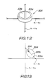
- Figs. 9 to 13 show an embodiment of an angle sensor 301 according to the present invention.
- 302 designates a ball-shaped hollow case.
- a circle mark 303 is written as a center position
- arrow marks 303a to 303d are written such that the arrow marks 303a to 303d indicate outer directions from the center position 303.
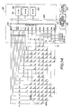
- lines X1 to X8 in a X-axis direction and lines Y1 to Y16 in a Y-axis direction are wired in a matrix in the inside surface of the case 302 (as shown in Fig. 14).
- Detectors 304 are provided at intersection points where the lines X1 to X8 cross the lines Y1 to Y16. As shown in Fig.
- the detector 304 has a pair of contacts 305a and 305b on an outside surface thereof and a diode (not shown) in the inside thereof.
- the contact 305a is connected to the lines X1 to X8 directly, and the contact 305b is connected to the lines Y1 to Y16 via a diode 306.
- mercury fluid 307 is enclosed within the case 302, hence, the contact 305a can be connected to the contact 305b via the mercury fluid 307 (i.e., the detector 304 is turned on).
- the lines X1 to X8 and the lines Y1 to Y16 are connected to an external device (not shown) via a cable 308 (as shown in Fig. 9).
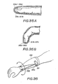
- the angle sensor 301 having the above-mentioned constitution is held by a hand H.
- the mercury fluid 307 must always moved downward within the case 302.
- an inclination of the angle sensor 301 varies the detector 304 which is turned on by the mercury fluid 307. Therefore, an inclination angle of the angle sensor 301 in the direction A and an inclination angle thereof in the direction B can be detected by detecting a combination of turn-on detectors 304 based on a turn-on state among the lines X1 to X8 and the lines Y1 to Y16.
- 309 designates resistors which pull down the lines X1 to X8, and 310 designates an I/O interface having output ports PA and PB connected to the lines Y1 to Y16 and an input port PC connected to the lines X1 to X8.
- 311 designates a central processing unit (CPU)
- 312 designates a read only memory (ROM) for storing predetermined programs used for the CPU 311
- 313 designates a random access memory (RAM) used for a work area
- 314 designates a bus line.
- the above-mentioned elements 309 to 314 constitute a musical tone control circuit 315.
- the CPU 311 sequentially selects one bit from bits PA0 to PA7 within the output port PA and bits PB0 to PB7 within the output port PB, and the CPU 311 sets a level of the selected one bit to the high (H) level.
- the "H" level signal is supplied to one of bits PC0 to PC7 within the input port PC via a certain line among the lines X1 to X8 which corresponds to a certain line having the H level among the lines Y1 to Y16.
- the the CPU 311 can detects that which detector 304 is turned on by monitoring the "H" level signal supplied to the bits PC0 to PC7.
- the CPU 311 can determine the inclination angle of the angle sensor 301 in the directions A and B based on the turn-on states of the detectors 304. Accordingly, the CPU 311 generates musical tone control data KC, the content of which corresponds to the inclination angle.
- the musical tone control data KC are supplied to a musical tone signal generating circuit 316 via the bus line 314.
- the musical tone signal generating circuit 316 generates a musical tone signal having a tone pitch corresponding to the value of the supplied musical tone control data KC.
- Such musical tone signal is supplied to a sound system 317 wherein a musical tone corresponding to the musical tone signal is generated.
- the sound system 317 In the case where the circle mark 303 can be seen at a top position of the angle sensor 301 as shown in Fig. 9, the sound system 317 generates a musical tone having a predetermined reference tone pitch. Thereafter, when the hand H is moved up and down in the direction A or the hand H is twisted in the direction B, the tone pitch of the musical tone generated from the sound system 317 must be varied in response to the moving direction of the angle sensor 301.
- the electronic musical instrument employing the angle sensor 301 can generate musical tones having various tone pitches which corresponds to the inclination of the angle sensor 301. For instance, when the angle sensor 301 held by the player's hand is moved, it is possible to generate various musical tones in response to the movement of the player's hand. Thus, it is possible to enjoy a musical performance based on a brand-new performance method which can not realized by the conventional electronic musical instrument.
- the tone pitch is varied in response to the inclination angle of the angle sensor 301 in the direction A and the tone volume is varied in response to the inclination angle of the angle sensor 301 in the direction B.
- the tone color and the like are varied in response to the inclination angle of the angle sensor 301.
- Fig. 15 contacts 320 are provided on the inside surface of the case 302 instead of the detectors 304, and a ball-shaped common electrode 321 is provided in a hollow inside portion of the case 302. Hence, the inclination angle of the case 302 varies a combination of contacts 320 which are connected to the common electrode 321 via the mercury fluid 307.
- the case 302 is shaped like a ball.
- the shape of the case 302 is not limited to the ball shape. Instead, it is possible to form the case as a cylindrical shape.
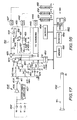
- Fig. 16 is a block diagram showing a first embodiment of the musical tone control apparatus according to the present invention.
- 1X, 1Y and 1Z designate acceleration sensors which respectively detect accelerations in a X-axis direction, a Y-axis direction and a Z-axis direction.
- these accelerations sensors 1X to 1Z are constructed by strain gauges which output acceleration signals corresponding to the above predetermined directions.
- these acceleration sensors 1X to 1Z are respectively attached to an edge portion of a drum stick 402 as shown in Fig. 17. Another edge portion of this drum stick 402 is held by the player's hand, hence, a musical tone corresponding to the swing movement will be generated when the player swings the drum stick 402.
- a tone color selecting switch SEL is mounted at the another edge portion of the drum stick 402. When the player depresses such switch SEL, a desirable tone color is selected.
- 405 designates an amplifier section which is constituted by a parallel circuit of a linear amplifier 406 and a logarithmic amplifier 407, and the amplifier section 405 amplifies the output signal of the acceleration sensor 1X.
- One of the linear amplifier 406 and the logarithmic amplifier 407 is selected by a select switch 408, hence, one of output signals of the linear amplifier 406 and the logarithmic amplifier 407 is supplied to an input terminal 411 of an acceleration peak detecting circuit 410 via the select switch 408.
- This acceleration peak detecting circuit 410 detects a peak value of the acceleration detected by the acceleration sensor 1X and also detects an acceleration increasing/attenuating duration.
- a non-inverting input terminal of a comparator 412 is connected to an input terminal 411 via a resistor 413 (having a resistance of 100 Kilo-Ohm).
- a resistor 415 (having a resistance of 10 Kilo-Ohm) and a capacitor 416 constitute an integration circuit for delaying an acceleration signal Sa inputted into the input terminal 411, and an output signal of such integration circuit is supplied to an inverting input terminal of the comparator 412 and a non-inverting input terminal of a comparator 420 via a diode D1 in a forward direction.
- a variable resistor VR divides a voltage V so as to set a reference voltage Vref, and the reference voltage Vref is supplied to an inverting input terminal of the comparator 420 via a resistor 423 (having a resistance of 100 Kilo-Ohm).
- the value of the reference voltage Vref varies due to a charging or a discharging of a capacitor 424 which grounds the inverting input terminal of the comparator 420.
- the inverting input terminal of the comparator 420 is connected to the non-inverting input terminal thereof via a resistor 422 and a diode D3 in forward direction, and such inverting input terminal is also connected to the input terminal 411 via a diode D2 in forward direction and via a resistor 421 (having a resistance of 10 Kilo-Ohm).
- the output signal of the comparator 412 is supplied to a clock input terminal of a delay flip-flop DFF1, the data input terminal D of which is supplied with a "1" signal.
- the output signal of the delay flip-flop DFF1 is supplied to a CPU 450 as an interrupt signal INT.
- the CPU 450 supplies a reset signal RS to the delay flip-flop DFF1.
- the output signal of the comparator 412 turns on or off a switching element 431.
- a capacitor 435 is charged via a first path comprising a resistor 432 and a switch 434 or via a second path comprising a constant current source 433 and the switch 434.
- the capacitor 435 is charged in a period when the output signal of the comparator 412 is identical to the "1" signal, and such period is converted into a charging voltage of the capacitor 435.
- a desirable charging characteristic of the capacitor 435 can be selected by selecting the switch 434.
- the charging voltage of the capacitor 435 is converted into a digital signal in an analog-to-digital (A/D) converter 442.
- a resistor 436 and a transistor 437 constitute a discharging path (or a reset path) of the capacitor 435.
- a base of transistor 437 is grounded via resistors 438 and 439, and the base of transistor 437 is also connected to the output terminal of the comparator 412 via the resistor 438 and a capacitor 440.
- the transistor 437 is turned on.
- a time-to-voltage (T/V) converter 430 is constituted as described heretofore.
- the output signal of the comparator 412 is supplied to a negative input terminal of an AND gate AN1, and the output signal of the comparator 420 is supplied to a positive input terminal of the AND gate AN1.
- the output signal of such AND gate AN1 is supplied to a T/V converter 445 which has the same circuit constitution of the T/V converter 430. This T/V converter 445 converts a period when the AND gate AN1 outputs the "1" signal into a voltage.
- the output signal of the T/V converter 445 is converted into a digital signal in an A/D converter 446.
- the acceleration peak detecting circuit 410 is constituted.
- This musical tone processing circuit 460 controls an operation for generating several kinds of musical tones based on output signals of A/D converters 427, 442 and 446. More specifically, the musical tone processing circuit 460 is constituted by registers 451, 452 and 453 for storing respective output data of the A/D converters 446, 442 and 427, the CPU 450 for controlling several portions within the circuit 460, a memory 455 for storing programs used in the CPU 450, registers 456 for once storing several kinds of data, switches 454 (including the select switch SEL shown in Fig. 17) for designating several kinds of commands and modes, and a tone generator 457 for generating a musical tone signal.
- the musical tone signal generated in the tone generator 457 is supplied to a sound system SS (not shown) wherein a musical tone corresponding to the supplied musical tone signal is generated.
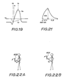
- the acceleration sensor 1X detects an acceleration of the drum stick 402 corresponding to the swing movement of the player, so that the acceleration sensor 1X outputs the acceleration signal to the input terminal 411 of the acceleration peak detecting circuit 410 as the acceleration signal Sa having a curve shown in Fig. 18(a).
- the swing movement of the player may have an acceleration characteristic where an acceleration is once given to the drum stick 402 in an inverting direction of the desirable swing direction (in a pre-movement period) and the acceleration is thereafter increased in the desirable swing direction. Thereafter, the value of the acceleration reaches to a peak value, and then the value of the acceleration attenuates so as to reach a "0" value.
- the pre-movement period is started at a time t10 (shown in Fig. 18(a)), and the swing movement in the desirable swing direction will be started at a time t11.
- the value of the acceleration signal Sa is smaller than that of the reference voltage Vref (as shown by a dashed line in Fig. 18(a)) in a period between the times t10 and t11.
- a value of an output signal Sd (as shown by a dotted line in Fig. 18(a)) of the integration circuit constituted by the resistor 415 and the capacitor 416 is smaller than that of the reference voltage Vref.
- the diode D1 shown in Fig.
- the reference voltage Vref is supplied to the inverting input terminal of the comparator 412 via the resistor 422 and the diode D3 in series, while the capacitor 424 starts to discharge its electric charge via the diode D2.
- the value of the reference voltage Vref is lowered so that the value of the reference voltage Vref becomes equal to that of the acceleration signal Sa at the time t11. Since a value of a forward voltage drop of the diode D3 is quite small, it can be considered that the reference voltage Vref is directly supplied to the inverting input terminal of the comparator 412.
- the voltage supplied to the inverting input terminal of the comparator 412 is higher than the voltage supplied to the non-inverting input terminal thereof until the time t11, whereby the output signal of the comparator 412 becomes identical to the "0" signal as shown in Fig. 18(b).
- a relation between the values of the acceleration signal Sa and the reference voltage Vref can be expressed as the following inequality (3) during a period between the times t11 and t12.
- the diodes D1 and D2 are turned off, and the diode D3 is turned on, whereby the comparator 412 performs a comparing operation for comparing the level of the acceleration signal Sa with that of the reference voltage Vref. Due to this comparing operation, the output signal of the comparator 412 turns up to the "1" signal at the time t11 as shown in Fig. 18(b).
- the diode D2 is turned off at the time t11, the discharge path of the capacitor 424 is cut off. Hence, the capacitor 424 is charged via the variable resistor VR and the resistor 423.
- the value of the reference voltage Vref increases gradually after the time t11, and thereafter, the level of the reference voltage Vref reaches at a predetermined initial voltage.
- the level of the signal Sd exceeds that of the reference voltage Vref at a time t12.
- the diode D1 is turned on and the diode D3 is turned off, hence, the comparator 412 performs the comparing operation thereof.
- the phase of the signal Sd is delayed by a minute time and the inclination of the curve of the signal Sd is slightly small. Therefore, a relation such as Sa > Sd is maintained until the value of the acceleration signal Sa reaches at the peak value, whereby the output level of the comparator 412 is maintained at the "1" level after the time t12.
- the output signal of the comparator 420 rises up to the "1" signal as shown in Fig. 18(c).
- the level of the signal Sd exceeds that of the acceleration signal Sa at a time t13, whereby the output signal of the comparator 412 falls down to the "0" signal as shown in Fig. 18(b).
- the level of the acceleration signal Sa does not exceed that of the signal Sd and that of the reference voltage Vref.
- the output level of the comparator 412 is maintained at the "0" level.
- the level of the signal Sd is higher than that of the reference voltage Vref, whereby the output level of the comparator 420 is maintained at the "1" level.
- the level of the reference voltage Vref exceeds that of the signal Sd, whereby the output signal of the comparator 420 falls down to the "0" signal. Since the level of the signal Sd is maintained lower than that of the reference voltage Vref after the time t14, the output level of the comparator 420 is maintained at the "0" level.
- the above-mentioned output signal of the comparator 420 is supplied to the positive input terminal of the AND gate AN1, while the output signal of the comparator 412 is inverted at the negative input terminal of the AND gate AN1.
- the output level of the AND gate AN1 becomes the "1" level during a period between the times t13 and t14 as shown in Fig. 18(d).
- the output level of the comparator 412 becomes the "1" level at the period between the times t11 and t13 as shown in Fig. 18(a). It is apparent from Fig. 18 that the time t11 can be identified as a time when the level of the acceleration signal Sa is inverted from the negative level to the positive level.
- the time t13 is approximately identical to a peak time when the value of the acceleration signal Sa reaches at the peak value.
- the level of the acceleration signal Sa (as an original signal) is compared with that of the delayed acceleration signal Sd, and a time when the level of the signal Sd exceeds that of the acceleration signal Sa is judged as the above peak time. Therefore, such detecting principle can detects the peak time with accuracy by properly selecting the delay time of the signal Sd.
- a period between the times t11 and t13 shown in Fig. 18 corresponds to a period when the acceleration is increasing.
- a time t14 when the output signal of the comparator 420 falls down is identical to a time when the level of the delay signal Sd becomes lower than that of the reference voltage Vref.
- a period Tr when the AND gate AN1 outputs the "1" signal corresponds to a period when the acceleration of the drum stick 402 is attenuating in the desirable swing direction.
- the high level period of the output signal of the comparator 412 means the acceleration increasing period.
- Such output signal of the comparator 412 is supplied to a terminal G of the switching element 425 and the T/V converter 430.
- the switching element 425 is subject to an open state in the acceleration increasing period, whereby the acceleration signal Sa is supplied to the capacitor 426 in the period Tw.
- a terminal voltage of the capacitor 426 will be increasing in the period Tw as shown in Fig. 18(e).
- the switching element 425 is turned off at the time t13 (i.e., the peak time of the signal Sa).
- a peak voltage of the signal Sa is held in the capacitor 426.
- the holding voltage of the capacitor 426 is sampled in the A/D converter 427 wherein the holding voltage is converted into a digital signal.
- the base current is flown into the base of transistor 437 via a differentiation circuit comprising the capacitor 440 and the resistor 438 at the time t11 when the output signal of the comparator 412 supplied to the T/V converter 430 rises up to the "1" signal.
- the electric charge of the capacitor 435 is discharged via the resistor 436 and the transistor 437.
- the terminal voltage of the capacitor 435 is reset to zero-volt (0V) as shown in Fig. 18(f) at the time t11.
- the switching element 431 is turned on at the leading edge timing t11 of the output signal of the comparator 412, whereby the capacitor 435 is charged via the resistor 432.
- the terminal voltage of the capacitor 435 will be increasing in accordance with a predetermined charging characteristic (shown by a full line in Fig. 18(f)) from the reset time t11.
- a predetermined charging characteristic shown by a full line in Fig. 18(f)
- the switch 434 is connected to the constant current source 433
- the terminal voltage of the capacitor 435 will be increasing in accordance with a predetermined charging characteristic shown by a dotted line in Fig. 18(f).
- the switching element 431 is turned off so that the charging of the capacitor 435 is stopped.
- the transistor 437 has been already turned off so that the terminal voltage of the capacitor 435 will be held after the time t13.
- the value of the holding voltage of the capacitor 435 must be determined based on a charging period of the capacitor 435, hence, such holding voltage corresponds to the period Tw shown in Fig. 18.
- such holding voltage is sampled and converted into a digital signal in the A/D converter 442 at a timing t s2 which is slightly delayed after the time t13.
- the AND gate AN1 outputs the output signal having the high level period Tr (i.e., the attenuating period Tr of the acceleration signal Sa) to the T/V converter 445 wherein a voltage corresponding to the period Tr is generated in a manner similar to that of the T/V converter 430.
- the output voltage of the T/V converter 445 is converted into a digital signal in the A/D converter 446 at a predetermined timing.
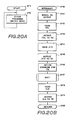
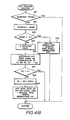
- the CPU 450 controls the musical tone processing circuit 460 in accordance with the flowcharts shown in Figs. 20A and 20B which are performed based on the programs stored in the memory 455.
- the CPU 450 starts the operation thereof at a step SP1 and then performs processes other than the process for generating musical tones at a step SP2 as shown in Fig. 20A.
- the CPU 450 scans the respective switches in the switches 454 so as to detect whether the tone color is changed or not, and the CPU 450 changes the tone color of the tone generator 457 so as to generate a musical tone having a selected tone color, for example.
- the CPU 450 repeatedly performs the processes in the step SP2 until the D flip-flop DFF1 (shown in Fig. 16) outputs the interrupt signal INT.
- the CPU 450 executes the processes in steps SP10 etc. shown in Fig. 20B.
- the CPU 450 outputs the reset signal RS so as to reset the D flip-flop DFF1 in a step SP11.
- This reset signal RS stops the D flip-flop DFF1 outputting the interrupt signal INT.
- the CPU 450 reads the data stored in the register 453 as volume data VOL.
- the A/D converters 427, 442 and 446 output respective digital signals corresponding to the peak value of the acceleration signal Sa, the increasing period Tw and the attenuating period Tr to the registers 453, 452 and 451, and these digital signals are used as the musical tone control data. More specifically, the data stored in the register 453 are used as the volume data VOL for controlling the tone volume, the data stored in the register 452 are used as attack data ATK for designating a rising timing when the musical tone is started to be generated, and the data stored in the register 451 are used as close (or decay) data CLS for designating an attenuating period of the musical tone.
- the CPU 450 When the CPU 450 reads the volume data VOL in the step SP12, the CPU 450 supplies such volume data VOL to the tone generator 457 so as to set the tone volume value of the musical tone signal in a step SP13.
- the CPU 450 reads the attack data ATK from the register 452 and supplies such attack data ATK to the tone generator 457 so as to set the rising timing of the musical tone signal in steps SP14 and SP15. Thereafter, the CPU 450 supplies a key-on command to the tone generator 457 in a step SP16. As a result, the tone generator 457 starts to generate the musical tone based on the attack data ATK and the volume data VOL.
- the CPU 450 reads the close data CLS from the register 451 in a step SP18.
- a next step SP19 such close data CLS are supplied to the tone generator 457 wherein the level of the musical tone signal is attenuated so that the musical tone signal has an attenuating envelope the value of which corresponds to that of the attenuating period designated by the close data CLS.
- a first process for generating the musical tone is completed.
- the operation of the CPU 450 returns to a main routine (i.e., the step SP2) of the interrupt process via a step SP20. Thereafter, such interrupt process (i.e., the process for generating the musical tone) will be repeatedly performed at every time when the D flip-flop DFF1 outputs the interrupt signal INT.
- the wait time in the step SP17 can be omitted in response to the kinds of the musical tones to be generated, if necessary.
- the first embodiment of the musical tone control apparatus can obtain the following specific effects.
- the conventional apparatus In order to detect the characteristics (i.e., the increasing period, the attenuating period, the peak value and the like) of the varying input signal such as the acceleration signal Sa, the conventional apparatus employs a first method for comparing the level of the input signal with a predetermined level, or the conventional apparatus employs a second method for converting the input signal into the digital signal and detecting the above periods and the peak value by use of a software process.
- the above first method extracts (or detects) a slow movement and a rapid movement of a human body as well.
- the CPU in each direction must be required in order to raise the processing speed and the processing accuracy.
- the conventional apparatus suffers problems in that the constitution thereof must be complicated and the cost thereof must be raised.
- the peak time of the input signal (the acceleration signal Sa) is detected by comparing the level of the input signal with that of the delayed input signal in the first embodiment.
- the first embodiment can detect the peak time and the peak value of the input signal based on a real time and with accuracy without using the CPU.
- the first embodiment can detect the acceleration increasing period and the acceleration attenuating period with accuracy because the level of the reference voltage Vref varies in response to that of the input signal.
- the digital signals respectively outputted from the A/D converters 427, 442 and 446 can be used for controlling other parameters of the musical tone such as the tone pitch, the tone color, the regist, the performance speed (or the tempo) of an automatic rhythm performance apparatus and the like.
- a musical tone generation due to the acceleration sensor 1X corresponds to a snare drum tone and a high hat open tone
- a musical tone generation due to the acceleration sensor 1Y corresponds to a bass drum tone and a high hat close tone. Accordingly, it is possible to generate a rhythm tone by swinging the drum stick 402 in horizontal and vertical directions. Thus, it is possible to generate two kinds of rhythm tones in a short time by rapidly changing the swing direction of the drum stick 402 from the horizontal direction to the vertical direction, for example.
- a various musical tone control can be done by use of the musical tone control apparatus combined with the angle sensor for detecting angles of the player's arm and the like.
- the angle of the player's arm controls the key code for designating the tone pitch
- the swing movement of the drum stick 402 controls the key-on timing (i.e., the start timing for generating the musical tone) and the envelope of the musical tone in an attack portion, a peak portion and a decay portion.
- Fig. 22A shows the player who swings the drum stick 402 downward by an arm angle of S1
- Fig. 22B shows the player who swings the drum stick 402 downward by an arm angle of S2.
- Fig. 23 shows an example of the angle sensor which is mounted at a predetermined position of a specific wear.
- AS1 and AS2 designate angle sensors for detecting angles between the arm and the body of the player.
- each of the angle sensors AS1 and AS2 is constituted by a rotary type potentiometer 480, an actuator 481 interlocked with a moving terminal of the potentiometer, a receiving member 482 for receiving the actuator 481 which can be slid freely and a spring 483 for pressing the actuator 481 against the receiving member 482.
- the actuator 481 When a relatively revolving movement is existed between the receiving member 482 and the potentiometer 480, the actuator 481 must revolve by a revolving number corresponding to the revolving movement with respect to the potentiometer 480. Thus, the angle signal can be obtained from the potentiometer 480.
- the potentiometer 480 is fixed at the shoulder of the player, and the receiving member 482 is fixed at an upper arm portion. Hence, the potentiometer 480 outputs an angle signal corresponding to the arm angle in the right and left directions of the player's body. As shown in Fig. 22, it is possible to detect the arm movement in the forward and backward directions of the player's body by changing the mounted positions of the angle sensors AS1 and AS2.
- angle sensors AS3 and AS4 are further provided so that the key code can be determined based on the combination of the output signals of the angle sensors AS1 to AS4. In this case, it is possible to select the key code in a wide tone range, and it is also possible to rapidly vary the key code. Thus, a brand-new performance effects can be obtained.
- Fig. 25 shows a movement of the angle sensor AS3 (or AS4) mounted at the player's elbow.
- Fig. 23 designates a case which provides the circuit shown in Fig. 16 and the sound system therein.
- the tone generator, the sound system and the like can be provided to the case externally.
- the angle sensor it is possible to use ultrasonic transmitters 495a and 496a and ultrasonic receivers 495b and 496b as shown in Fig. 26.
- the arm angle can be detected based on the transmitting time of the ultrasonic waves which are transmitted between the ultrasonic transmitters 495a and 496a and the ultrasonic receivers 495b and 496b.
- acceleration sensors 1X, 1Y and 1Z are provided within the drum stick 402. Instead, acceleration sensors can be mounted directly or indirectly at several portions of the player's body such as hands, feet, a neck, arms and the like. In this case, the accelerations at the above portions of the player's body will be detected.
- Fig. 27 shows an example of such acceleration sensor which is mounted at the glove for the player's hand.
- the acceleration sensors 1X, 1Y and 1Z and the like are mounted at respective finger tip portions of a glove 498. Due to such constitution, it is possible to detect several accelerations in response to the swing movement of the player's hand etc. Hence, the player can perform several kinds of performances by his daily movement without using the musical instruments such as the drum stick 402.
- Fig. 29 shows an appearance of a player who is mounted with a second embodiment of the musical tone control apparatus according to the present invention
- Fig. 30 is a block diagram showing an electric constitution of the second embodiment.
- the second embodiment is constituted by a control unit 501, a detecting section 502 for the player's right elbow, a detecting section 503 for the player's left elbow and a detecting section 504 for the player's right hand.
- the control unit 501 is mounted at the player's waste by a belt 505.
- the detecting sections 502, 503 and 504 are respectively mounted at the right elbow, the left elbow and the right hand of the player.
- the control unit 501 includes a musical tone control apparatus, a musical tone generating circuit (which is controlled by the musical tone control apparatus) and a speaker.
- the detecting section 502 is constructed as shown in Fig. 31.
- 507a designates a mounting member such as a supporter made of flexible fiber materials, and this mounting member 507a has a shape which is fitted for the right elbow.
- a thin type potentiometer 508a is mounted at a predetermined portion of the mounting member 507a covering the joint of the player's right elbow.
- a lever 510a is fixed at a shaft 509a of the potentiometer 508a, and the tip end portion of the lever 510a can be freely put out and put in a cylinder 512a as shown in Fig. 32.
- a spring 513a for pulling the lever 510a is provided within the cylinder 512a.
- a fixing portion 514a is formed at an edge portion of the cylinder 512a, and this fixing portion 514a is mounted at the center of the arm portion of the mounting member 507a.
- a detection signal (a voltage signal) corresponding to the revolving angle of the shaft 509a (i.e., the bending angle of the player's right elbow) is generated in the potentiometer 508a, and such detection signal is supplied to the control unit 501 via a cable 515a.
- the detecting section 503 is constructed by elements 507b to 515b which are similar to the elements 507a to 515a of the detecting section 502, hence, the detailed description of the construction of the detecting section 503 will be omitted.
- Figs. 33 and 34 designates a glove made of flexible fiber materials, and a potentiometer 508c is mounted at a portion of the glove 516 covering the joint of the player's right hand. Similar to the detecting section 502, a lever 510c is fixed at the edge portion of the shaft 509c of the potentiometer 508c, and the lever 510c can be freely put out and in a cylinder 512c. In addition, a fixing portion 514c is formed at an edge portion of the cylinder 512c, and the fixing portion 514c is attached at the base of fingers of the glove 516.
- a detection signal (a voltage signal), the value of which corresponds to a bending angle of the player's right hand.
- detection signal is supplied to the control unit 501 via a cable 515c.
- pressure sensitive elements 517a to 517d are provided in the inside of the finger tip portions 516a to 516d of the glove 516. Each of these pressure sensitive elements 517a to 517d has a specific resistance which varies in response to the pressure given by each finger of the player's right hand. As shown in Fig.
- each pressure sensitive element generates the detection signal having a value corresponding to the bending angle of each finger tip, and such detection signal will be supplied to the control unit 501 via the cable 515c.
- a piezoelectric element for generating a voltage corresponding to the given pressure thereof as the pressure sensitive element.
- 520 shown in Fig. 30 designates an analog multiplexer having seven channels.
- Such analog multiplexer 520 selects one of the detection signals from the potentiometers 508a to 508c and the detection signals from the pressure sensitive elements 517a to 517d based on a channel select signal CS which is supplied to a select terminal of the analog multiplexer 520. Then the analog multiplexer 520 supplies the selected detection signal to an A/D converter 521 wherein the selected detection signal is converted into digital detection data of predetermined bits.
- 522 designates a CPU
- 523 designates a ROM for storing programs used in the CPU 522
- 524 designates a RAM which is used as a work area.
- the CPU 522 generates the channel select signal CS, the value of which is sequentially varied.
- Such channel select signal CS is supplied to the analog multiplexer 520, whereby the analog multiplexer 520 scans the output signals of the potentiometers 508a to 508c and the pressure sensitive elements 517a to 517d with a relatively high speed.
- the CPU 522 judges the bending angles of the player′s right elbow and the player′s left elbow in accordance with predetermined four angles based on the detection data outputted from the A/D converter 521.
- the CPU 522 generates key code data KC in response to a combination of the bending angles of the player's right elbow and the player's left elbow based on the above judging result.
- the CPU 522 judges the bending angle of the player's right hand in accordance with predetermined three angles based on the detection data corresponding to the detection signal from the potentiometer 508c. More specifically, the CPU 522 generates the tone volume data VOL representative of the tone volume (which can be classified by large, medium and small tone volumes) in response to the bending angle of the player's right hand. Furthermore, the CPU 522 judges whether each of an index finger, a middle finger, a third finger and a little finger of the player's right hand is bent or not based on the detection data corresponding to the detection signals from the pressure sensitive elements 517a to 517d.
- the CPU 522 Based on this judging result, the CPU 522 generates tone color select data TD for selecting a tone color (such as a tone color of the piano, the organ, a flute, a saxophone, a clarinet or the like) in response to a combination of bent fingers.
- a tone color such as a tone color of the piano, the organ, a flute, a saxophone, a clarinet or the like
- the CPU 522 supplies the above-mentioned key code data KC, the volume data VOL and the tone color select data TD (i.e., the musical tone control data) to a musical tone signal generating circuit 526.
- the musical tone signal generating circuit 526 generates a musical tone signal having a tone pitch corresponding to the key code data KC, a tone volume corresponding to the tone volume data VOL and a tone color corresponding to the tone color select data TD.
- a speaker 527 generates a musical tone corresponding to a musical tone signal generated in the musical tone signal generating circuit.
- a transmitter circuit 528 transmits the musical tone signal outputted from the musical tone signal generating circuit 526 by wireless.
- the tone pitch of the musical tone generated from the speaker 527 of the control unit 501 in response to the combination of the bending angles of the joints of the player's right and left elbows.
- the tone pitch and the like are controlled based on the detection result of the potentiometer 508a to 508c which detect the bending angles of the joints of the player's elbows and the player's wrist.
- a potentiometer 531 is mounted at the inside of a mounting member 530 such as a supporter covering the player's arm; a certain bending is given to a shaft 531a of the potentiometer 531; an edge portion of the shaft 531a is fixed at an edge portion of a rod 532 made of plastics having a small twist characteristic; another edge portion of the rod 532 is attached to the inside of wrist portion of the mounting member 530.
- a twist angle of the player's arm or a revolving angle of the player's wrist
- the tone pitch, the tone color and the tone volume are controlled based on such detecting result.
- 540 designates a mounting wear covering the breast, shoulders and elbows of the upper half of the player's body. Similar to the ordinary wear, this mounting wear 540 can be taken off.
- shoulder portions 540a and 540b, and elbow portions 540c and 540d are made of flexible fiber materials.
- thin type absolute rotary encoders 541a to 541d are mounted respectively at the shoulder portions 540a and 540b, and the elbow portions 540c and 540d. These rotary encoders 541a to 541d have respective shafts, the edge portions of which are fixed to levers 542a to 542d.
- the edge portions of the levers 542a to 542d are mounted to a mounting member 540 via respective absorber members 543a to 543d made of flexible materials such as a rubber and the like.
- the rotary encoder 541a detects the revolving angle at the joint of the player's right shoulder
- the rotary encoder 541b detects the revolving angle of the joint of the player's left shoulder.
- the rotary encoder 541c detects the bending angle of the joint of the player's right elbow
- the rotary encoder 541d detects the bending angle of the joint of the player's left elbow.
- control unit 501a Similar to the control unit 501 shown in Fig. 30, the control unit 501a comprises the CPU 522, the ROM 523, the RAM 524, the bus line 525, the musical tone signal generating circuit 526, the speaker 527, the transmitter circuit 527 and further comprises registers for once storing the angle detecting signals outputted from the rotary encoders 541a to 541d.
- the CPU 522 sequentially reads the angle detecting signals stored in the above registers so as to generate tempo data representing the performance speed of the generated musical tones. Such tempo data are supplied to the musical tone signal generating circuit 526 via the bus line 525. Hence, the musical tone signal generating circuit 526 generates the musical tone signal (for generating a percussive tone such as the drum tone, the cymbal tone and the like) having the performance speed corresponding to the tempo data and also having the predetermined rhythm pattern.
- the performance speed of the percussive tone generated from the speaker 527 can be freely varied in response to the revolving angles of the joints of the player's shoulders and the bending angles of the joints of the player's elbows.
- this first modified embodiment can be constituted such that the key code data KC, the tone volume data VOL and the tone color select data TD can be generated based on the angle detecting data obtained by the rotary encoders 541a to 541d, and the tone pitch, the tone volume and the tone color can be controlled based on these respective data.
- the apparatus comprises ultrasonic transmitters 551a and 551b, ultrasonic receivers 552a and 552b, and a control unit 501b.
- Theses ultrasonic transmitters 551a and 551b are respectively mounted to insides of the player's right and left arms by a mounting member 550 such as a supporter, and the ultrasonic receivers 552a and 552b are mounted at the player's waste by the belt 505.
- these transmitters 551a and 551b and receivers 552a and 552b are constructed by the piezoelectric elements such as barium titanate vibrators.
- each of the transmitters 551a and 551b is constructed by four transmitting piezoelectric elements T1 to T4 which are arranged by respective angles St1 to St4 with respect to a base plane B1.
- each of the receivers 552a and 552b is constructed by two receiving piezoelectric elements R1 and R2 which are arranged by respective angles Sr1 and Sr2 with respect to a base plane B2.
- a position of the transmitter 551a is changed as shown by positions P1, P2, P3 and P4 with respect to a position P0 of the receiver 552a which is mounted at the player's waste while the player swings down his right arm.
- the ultrasonic wave transmitted from the transmitter 551a must be reached at the receiver 552a, regardless of a relative position relation between the transmitter 551a and the receiver 552a.
- a distance between the positions P0 and P1 is equal to 60 cm
- a distance between the positions P0 and P2 is equal to 47 cm
- a distance between the positions P0 and P3 is equal to 28 cm
- a distance between the positions P0 and P4 is equal to 15 cm.
- a start pulse generator 555 generates a start pulse SP having a constant cycle.
- Such start pulse SP is supplied to an input terminal of an ultrasonic pulse generator 556, and set input terminals S of R-S flip-flops 557a and 557b.
- the above start pulse SP triggers the ultrasonic pulse generator 556 so that the ultrasonic pulse generator 556 outputs an ultrasonic pulse UP to the transmitters 551a and 551b.
- the transmitters 551a and 551b transmit respective ultrasonic waves each having a constant cycle to the receivers 552a and 552b wherein the high frequency voltages are generated.
- the receiver 552a outputs the high frequency voltage to an amplifier 558a wherein the high frequency voltage is amplified, and an amplified signal S a is rectified in a diode 559a and then supplied to a reset input terminal R of a R-S flip-flop 557a.
- the R-S flip-flop 557a is set by the start pulse SP and reset by an output signal of the diode 559a. Therefore, the R-S flip-flop 557a outputs an output signal S a1 from an output terminal Q thereof, and such output signal S a1 has a pulse width the value of which corresponds to a distance la between the transmitter 551a and the receiver 552a.
- This output signal S a1 is supplied to one input terminal of an AND gate 560a, whereby the AND gate 560a is subject to an open state so that a clock pulse CP is supplied to a clock input terminal CK of a counter 561a via the AND gate 560a in a pulse width period of the signal S a1 .
- the counter 561a counts up the clock pulse CP so as to output the count value thereof.
- Such count value corresponds to the distance la between the transmitter 551a and the receiver 552a. In other words, such count value corresponds to the revolving angle of the player's right arm which is swung down to his body.
- the high frequency voltage outputted from the receiver 552b is amplified in an amplifier 558b, and an amplified signal S b is rectified in a diode 559b and then supplied to a reset input terminal R of a R-S flip-flop 557b.
- the R-S flip-flop 557b is set by the start pulse SP and reset by an output signal of the diode 559b. Therefore, the R-S flip-flop 557b outputs an output signal S b1 from an output terminal Q thereof, and such output signal S b1 has a pulse width the value of which corresponds to a distance lb between the transmitter 551b and the receiver 552b.
- This signal S b1 is supplied to one input terminal of an AND gate 560b, whereby the AND gate 560b is subject to the open state so that the clock pulse CP is supplied to a clock input terminal CK of a counter 561b via the AND gate 560b in a pulse width period of the signal S b1 .
- the counter 561b counts up the clock pulse CP so as to output a count value thereof.
- Such count value corresponds to the distance lb between the transmitter 551b and the receiver 552b. In other words, such count value corresponds to the revolving angle of the player's left arm which is swung down to his body.
- An ultrasonic measuring circuit 570 is constituted as described heretofore.
- the above-mentioned count values of the counters 561a and 561b are supplied to a musical tone control data generating circuit 563.
- the count value of the counter 561a is inputted into the musical tone control data generating circuit 563 at a trailing edge timing of the signal S a1 (i.e., a timing when the R-S flip-flop 557a is reset). Slightly thereafter, the musical tone control data generating circuit 563 supplies a reset pulse RPa to a reset input terminal R of the counter 561a so that the counter 561a is reset.
- the count value of the counter 561b is inputted into the musical tone control data generating circuit 563 at a trailing edge timing of the signal S b1 (i.e., a timing when the R-S flip-flop 557b is reset). Slightly thereafter, the musical tone control data generating circuit 563 supplies a reset pulse RPb to a reset input terminal R of the counter 561b so that the counter 561b is reset.
- the musical tone control data generating circuit 563 generates and outputs musical tone control data (i.e., the data KC, VOL and TD described before) to the musical tone signal generating circuit 526.
- the musical tone signal generating circuit 526 generates the musical tone signal whose tone pitch, tone color and tone volume (or a performance speed) are varied based on the value of the musical tone control data.
- Such musical tone signal is outputted to the speaker 527.
- the speaker 527 generates a musical tone corresponding to the revolving angles of the player's right and left arms which are swung down to his body.
- the second modified embodiment described above it is possible to detect the revolving angle of the player's right arm which is swung to his body based on a period for transmitting the ultrasonic wave between the transmitter 551a mounted at his right arm and the receiver 552a mounted at his right waste.
- the tone pitch, the tone color and the tone volume of the musical tone or the performance speed are varied in response to the revolving angles of the player's right and left arms.
- the performance speed in response to the bending angles of the player's elbows and it is also possible to vary the tone pitch of the musical tone in response to the bending angles of the player's fingers in the second modified embodiment.
- Fig. 41 is a block diagram showing a third embodiment of the musical tone control apparatus according to the present invention, and Fig. 42 shows an appearance of a stick 601 used in this third embodiment.
- a base portion of the stick 601 has a shape which can be held by the player's hand H, and an angle detector 602 is provided in the inside of a tip edge portion 601b of the stick 601.
- a # (sharp) key-on switch Ks, a key-on switch Kn and a b (flat) key-on switch Kf are mounted on a center portion 601c of the stick 601. These switches Ks, Kn and Kf can be depressed by a thumb or an index finger of the player's hand H which holds the base portion 601a.
- the angle detector 602 is constituted by a supporting plate 603 and four detecting switches a to d attached to the supporting plate 603. These detecting switches a to d are arranged by respective angles of 22.5 degrees, 67.5 degrees, 112.5 degrees and 157.5 degrees with respect to a reference line L.
- each of the detecting switches a to d is constructed by a glass tube 604, mercury fluid 605 and a pair of electrodes 606a and 606b.
- the glass tube 604 is closely packed and enclosed by a certain volume of the mercury fluid 605, and the electrodes 606a and 606b are inserted through an edge wall of the glass tube 604. In a state as shown in Fig.
- the electrode 606a is not connected to the electrode 606b, hence, this detecting switch is turned off.
- the electrode 606a When the edge portion of the glass tube 604 inserted by the electrodes 606a and 606b is inclined downward in a direction as shown by an arrow in Fig. 44, the electrode 606a will be connected to the electrode 606b via the mercury fluid 605 so that this detecting switch will be turned on.
- the angle detector 602 shown in Fig. 43 is revolved around the reference point O, the on/off states of the detecting switches a to d becomes as shown by Fig. 45. More specifically, all of the detecting switches a to d are turned off in the state shown in Fig. 43.
- the angle detector 602 revolves around the reference point O in a direction Y (i.e., in a counter-clockwise direction) by 45 degrees, only the detecting switch a is turned on.
- the detecting switches a and b are turned on.
- the detecting switches which are turned on are identified as the detecting switches a, b and c; the detecting switches a, b, c and d; the detecting switches b, c and d; the detecting switches c and d; the detecting switch d.
- Fig. 41 the electrode 606a of each of the detecting switches a to d mounted in the stick 601 is grounded, and the electrodes 606b of the detecting switches a to d are respectively connected to one terminals of pull-up resistors ra to rd and also connected to 0-bit to 3-bit of an A register 608.
- these 0-bit to 3-bit of the A register 608 store respective detection data Da to Dd corresponding to on/off states of the detecting switches a to d.
- one terminals of the # key-on switch Ks, the key-on switch Kn and the b key-on switch Kf mounted on the stick 601 are grounded, and other terminals thereof are connected to respective one terminals of pull-up resistors rs, rn and rf and also connected to a B register 609 of three bits.
- 0-bit to 2-bit of the B register 609 store respective operation data Ds, Dn and Df corresponding to on/off states of the key-on switches Ks, Kn and Kf.
- each value of the above detection data Da to Dd and the operation data Ds, Dn and Df becomes identical to "0" when each of the detecting switches a to d and the key-on switches Ks, Kn and Kf is turned on.
- each value of such data becomes identical to "1" when each of such switches is turned off.
- a musical tone control circuit 614 is constituted by the registers 608 and 609, a CPU 610, a ROM 611 for storing predetermined programs used in the CPU 610, a RAM 612 used as a work area and a bus line 613.
- the CPU 610 executes processes which will be described later, the CPU 610 generates key code data KC, a key-on signal KON and a key-off signal KOF based on the detecting data Da to Dd stored in the A register 608 and based on the operation data Ds, Dn and Df stored in the B register 609.
- Such key code data KC, key-on signal KON and key-off signal KOF are supplied to a musical tone signal generating circuit 615 via the bus line 613.
- the musical tone signal generating circuit 615 Based on the above key code data KC, the key-on signal KON and the key-off signal KOF, the musical tone signal generating circuit 615 generates a musical tone signal. More specifically, the musical tone signal generating circuit 615 generates the musical tone signal having the tone pitch corresponding to the value of the key code data KC and the predetermined tone color. This musical tone signal is supplied to a sound system 616 wherein a musical tone corresponding to the musical tone signal is generated.
- Fig. 47 shows a flowchart of a main routine which will be repeatedly performed by the CPU 610 in a normal mode.
- the CPU 610 reads the operation data Ds, Dn and Df stored in the B register 609 in a step S1. Next, the CPU 610 judges whether the key-on switch Kn is depressed or not based on the operation data Dn in a step S2. In this case, the CPU 610 judges that the key-on switch Kn is depressed when the value of the operation data Dn is equal to "0", and the process advances to a next step S3. On the other hand, the CPU 610 judges that the key-on switch Kn is not depressed when the value of the operation data Dn is equal to "1", and the process advances to a next step S4.
- the CPU 610 judges whether the # key-on switch Ks is depressed or not based on the operation data Ds. In this case, the CPU 610 judges that the # key-on switch Ks is depressed when the value of the operation data Ds is equal to "0", and the process advances to a next step S5. On the other hand, the CPU 610 judges that the # key-on switch is not depressed when the value of the operation data Ds is equal to "1", and the process advances to a next step S6. In this step S6, the CPU 610 judges whether the b key-on switch Kf is depressed or not based on the operation data Df.
- the CPU 610 judges that the b key-on switch Kf is depressed when the value of the operation data Df is equal to "0", and the process advances to a next step S7.
- the CPU 610 judges that the b key-on switch Kf is not depressed when the value of the operation data Df is equal to "1”, and the process advances to a next step S8.
- a value of key-on data KOND stored in a predetermined area of the RAM 612 is set equal to "-2", and then the process advances to a next step S9.
- step S9 represents a key processing routine which will be described later. After the process in the step S9 is executed, the process returns to the step S1 again.
- the CPU 610 judges whether old key-on data OLDKOND pre-stored in the predetermined area of the RAM 612 coincide with new key-on data KOND or not in a step SP1.
- the process returns to the main routine.
- the old key-on data OLDKOND do not coincide with the key-on data KOND
- the process advances to a next step SP2.
- the old key-on data OLDKOND pre-stored in the RAM 612 are re-written by the new key-on data KOND.
- the CPU 610 judges whether the value of the key-on data KOND equals to "-2" or not.
- step SP4 When the value of the key-on data KOND equals to "-2", the process advances to a step SP4. When the value of the key-on data KOND does not equal to "-2", the process advances to a step SP5. In this step SP5, the CPU 610 reads the detecting data Da to Dd stored in the A register 608. In a next step SP6, the CPU 610 determines the value of the key code data KC based on a combination of the detecting data Da, Db, Dc and Dd. In this case, Fig. 46 represents relations between the value of the key code data KC and the combination of the detecting data Da, Db, Dc and Dd. For example, when the position of the angle detector 602 is set as shown in Fig.
- the CPU 610 judges whether the value of the key code data KC is equal to "0" or not in a step SP7.
- the process returns to the main routine.
- the process advances to a next step SP8.
- the key code data KC are added with the key-on data KOND so as to obtain an addition result, and such addition result is set identical to the new key code data KC.
- the value of the key-on data KOND is set identical to "+1" in the step S5 within the main routine described before.
- the value of the old key code data KC OLD is added with the value "1" in the step SP8 so that the old key code data KC OLD are converted into new key code data KC having a tone pitch which is higher than that of the old key code data KC OLD by a chromatic semi-tone.
- the old key code data KC OLD (having the value "60") corresponding to the tone pitch C3 are converted into the new key code data KC (having the value "61") corresponding to a tone pitch C#3, for example.
- the value of the key-on data KOND is set equal to "-1" in the step S7 within the main routine.
- the value "1" is subtracted from the value of the old key code data KC OLD in the step S8 so that the old key code data KC OLD are converted into the new key code data KC having a tone pitch which is lower than that of the old key code data KC OLD by the chromatic semi-tone.
- the old key code data KC OLD (having the value "60") corresponding to the tone pitch C3 are converted into the new key code data KC (having the value "59") corresponding to a tone pitch Cb3 (B2).
- the CPU 610 outputs the new key code data KC the value of which is calculated in the step SP8 in a step SP9, and then the CPU 610 outputs the key-on signal KON.
- Such data KC and the signal KON are sequentially supplied to the musical tone signal generating circuit 615 via the bus line 613.
- the musical tone signal generating circuit 615 starts to generate the musical tone signal, and such musical tone signal is supplied to the sound system 616 wherein the musical tone having the tone pitch corresponding to the key code data KC is generated.
- the value of the key-on data KOND is set equal to "-2" in the step S8 within the main routine described before.
- the CPU 610 judges that the value of the key-on data KOND equals to "-2" in the step SP3 within the key processing routine, and the process advances to the next step SP4.
- the CPU 610 generates the key-off signal KOF, and this key-off signal KOF is supplied to the musical tone signal generating circuit 615 via the bus line 613.
- the musical tone signal generating circuit 615 stops generating the musical tone signal, whereby the sound system 616 stops generating the musical tone. Thereafter, the process of the CPU 610 returns to the main routine again.
- the third embodiment of the present invention performs the operation for generating the musical tone.
- the third embodiment in the case where the player's hand H holding the stick 601 as shown in Fig. 41 is swung up and down and the key-on switch Kn is depressed by the thumb of the player's hand H, it is possible to generate the musical tone having the tone pitch corresponding to the moving direction of the player's hand H, i.e., corresponding to the movement of the player's arm and body.
- the tone pitch can be raised by the chromatic semi-tone by depressing the # key-on switch Ks, and the tone pitch can be lowered by the chromatic semi-tone by depressing the b key-on switch Kf.
- This modified embodiment is constituted such that the tone pitch and the tone generating timing can be controlled by using two sticks 601R and 601L each having the same constitution similar to the constitution of the stick 601.
- This modified embodiment further provides an A register 608a of four bits other than the A register 608 within the musical tone control circuit 614.
- the detecting data Da to Dd outputted from the stick 601R are stored in the A register 608, and other detecting data Da to Dd outputted from the stick 601L are stored in the A register 608a.
- respective operation data Ds outputted from the sticks 601R and 601L are combined into one operation data Ds under an logical AND operation.
- respective operation data Dn and respective operation data Df outputted from the sticks 601R and 601L are combined into one operation data Dn and one operation data Df under the logical AND operation.
- Such combined operation data Ds, Dn and Df are stored in the B register 609. Hence, the performance is done by the player M who holds the sticks 601R and 601L in his right and left hands respectively as shown in Fig. 49A.
- each of the sticks 601R and 601 provides the key-on switches Ks, Kn and Kf.
- one of the sticks 601R and 601L provides the key-on switches Ks, Kn and Kf.
- the stick 601R provides the switches Ks and Kf and the stick 601L provides the switch Kn, for example.
- the tone pitch of the musical tone to be generated is determined by the combination of the respective detecting data Da to Dd outputted from the sticks 601R and 601L.
- the performance will be done as shown in Figs. 49B to 49E, for example.
- the tone pitch will be varied in a sequence of C3, D3 and E3, for example.
- the tone pitch will be varied in a sequence of F3, G3 and A3, for example.
- a tone pitch C4 can be obtained.
- a tone pitch D3 or G4 can be obtained.
- Figs. 49F to 49I show other examples of performance.
- the tone pitch will be varied in a sequence of C2, D2, E2, F2 and G2, for example.
- the tone pitch will be varied is a sequence of G2, A2, B2, C3 and D3, for example.
- a tone pitch E3 can be obtained.
- a tone pitch C3 or F4 can be obtained.
- the stick 601 provides an octave switch and this octave switch is turned on or off so as to raise or lower the tone pitch by one octave.
- the angle detector 602 is provided in the inside of the cylindrical stick 601 in the embodiments described heretofore.
- the shape of the stick is not limited to the cylindrical stick 601, and it is possible to construct the stick 601 in an arbitrary shape.
- the tone pitch of the musical tone to be generated is varied in response to the force given to the angle detector 602 in the embodiments described heretofore.
- the angle detector 602 it is possible to vary the tone color and the tone volume in response to the force given to the angle detector 602, or it is possible to control the musical tone to be generated or not based on such force. Furthermore, it is possible to mount the angle detector 602 to the player's feet or body to thereby control the musical tone in response to the movement of the player's feet and the like.
- Fig. 50 shows a rhythm stick 701R for the player's right hand and a rhythm stick 701L for the player's left hand according to a fourth embodiment of the musical tone control apparatus according to the present invention.
- 705 and 706 designate pushbutton switches of the stick 701R.
- the pushbutton switch 705 is mounted at a position where the thumb of the player's right hand can reach and the pushbutton switch 706 is mounted at a position where the index finger of the player's right hand can reach when the player holds a holding portion 701a of the stick 701R by his right hand.
- These switches 705 and 706 are respectively connected to an interface circuit 707 shown in Fig. 51.
- an angle detector 702R is mounted within a tip edge portion of the stick 701R.
- This angle detector 702R provides five mercury switches D1R to D5R each of which is connected to the interface circuit 707. Furthermore, respective one terminals of the switches 705, 706 and the mercury switches D1R to D5R are supplied with a constant voltage V via respective resistors (R), and respective other terminals thereof are grounded to (GND).
- the stick 701L provides pushbutton switches 708 and 709 (corresponding to the pushbutton switches 705 and 706) and also provides an angle detector 702L (corresponding to the angle detector 702R).
- the switches 708, 709, and mercury switches D1L to D5L mounted in the angle detector 702L are connected to the interface circuit 707 respectively.
- This interface circuit 707 detects angles of the player's right and left arms with respect to the plumb line based on output signals of the mercury switches D1R to D5R and the mercury switches D1L to D5L as well, and this interface circuit 707 generates angle data KD1 and KD2 based on the detecting result of the angles of the player's arms. Such angle data KD1 and KD2 are sequentially supplied to a musical tone control circuit 710.
- the interface circuit 707 detects on/off states of the switches 705, 706, 708 and 709 so as to generate respective signals S1, S2, S3 and S4. Each of these signals S1 to S4 has a "H" (High) level when each of the switches 705, 706, 708 and 709 is depressed.
- each of these signals S1 to S4 has a "L" (Low) level when each of the switches 705, 706, 708 and 709 is released.
- These signals S1 to S4 are supplied to the musical tone control circuit 710.
- this musical tone control circuit 710 checks each value of the signals S1 and S2, and the musical tone control circuit 710 generates tone pitch data KC based on the angle data KD1 and KD2 when both of the signals S1 and S2 are identical to the "0" signal (i.e., when both of the switches 705 and 706 are turned off).
- the musical tone control circuit 710 generates the tone pitch data KC, the value of which corresponds to one of the tone pitches F2, G2, A2, ..., C5, D5, E5.
- the value of the tone pitch data KC is raised by the chromatic semi-tone (#; sharp) when the signal S3 is identical to the "1" signal (i.e., when the switch 708 is turned on), and the value of the tone pitch data KC is lowered by the chromatic semi-tone (b; flat) when the signal S4 is identical to the "1" signal (i.e., when the switch 709 is turned on).
- Such tone pitch data KC are sequentially supplied to a musical tone signal generating circuit 711.
- the musical tone control circuit 710 when both of or one of the signals S1 and S2 is identical to the "1" signal (i.e., when both of or one of the switches 705 and 706 is turned on), the musical tone control circuit 710 generates chord data KM in accordance with the on/off states of the switches 705, 706, and the values of the angle data KD1 and KD2.
- F2# to F3, F3# to F4 and F4# to E5 represent respective ranges of the tone pitches which are determined based on the swing angles of the player's right and left arms as shown in Fig. 52.
- the on/off states of the switches 705 and 706 shown in the upper rows in Fig.
- the musical tone control circuit 710 generates the chord data KM corresponding to one of chord kinds of Major, 7th, miner, M7 (7th), m7 (7th), b5 (5th), M6 (6th), dim (diminution), Aug (Augmentation).
- the tone pitch is determined to B3 as shown in Fig. 52.
- the switch 705 is turned on and the switch 706 is turned off, the chord of M7 is selected in accordance with the tone pitch B3.
- both of the switches 705 and 706 are turned on, the chord of B3-m7 is selected.
- the musical tone control circuit 710 when the switch 705 is turned off and the switch 706 is turned on, the chord of B3-b5 is selected.
- the musical tone control circuit 710 generates the chord data KM corresponding to the chord of M7, B3-m7 or B3-b5, and such chord data KM are sequentially supplied to a musical tone signal generating circuit 712 wherein a chord accompaniment signal corresponding to the chord data KM is generated.
- the musical tone signal generating circuit 711 generates a melody tone signal having the tone pitch corresponding to the tone pitch data KC which are outputted from the musical tone control circuit 710.
- a speaker SP is driven based on the chord accompaniment signal and the melody tone signal.
- the speaker SP when the player swings up his arms holding the sticks 701R and 701L and releases the switches 705 and 706, the speaker SP generates a melody tone having the tone pitch corresponding to the swing angles of the player's arms and the on/off states of the switches 708 and 709. In this state, when the player depresses one of or both of the switches 705 and 706, the speaker SP generates the accompaniment tone corresponding to the swing angles of the player's arms and the on/off states of the switches 705, 706, 708 and 709.
- the angle detectors 702R and 702L mounted within the sticks 701R and 701L are used for detecting the swing angles of the player′s arms.
- an angle detector 715 as shown in Fig. 54A.
- the player holds a stick 703 mounted with switches 713 and 714 (corresponding to the switches 705 and 706), and the angle detector 715 is mounted at the player's right elbow in order to detect the bending angle of the player's right elbow.
- the player's left arm has the same constitution as shown in Fig. 54A, hence, the drawing thereof and the description thereof will be omitted.
- Fig. 55 shows a detailed constitution of the player's right elbow shown in Fig. 54A.
- 716 designates a mounting wear covering the upper half of the player's body
- 717 designates a supporter which is made of flexible fiber materials such as the rubber material and which covers the joint portion of the player's right elbow.
- This supporter is mounted with a resistor 718 of the angle detector 715 at a portion covering the joint of the player's right elbow.
- This angle detector 715 is constituted such that a lever 719 is fixed at a shaft 718a of the resistor 718 and a tip edge portion of the lever 719 can be freely put out and in a cylinder 720.
- a spring is provided in the inside of the cylinder 720 in order to pull the lever 719.
- a fixing portion 720a is formed at an edge portion of the cylinder 720, and this fixing portion 720a is mounted at a certain portion of the mounting wear 716 which covers the player's right arm.
- the lever 719 and the cylinder 720 vibrates in response to a movement for bending or stretching the player's right elbow so that the shaft 718a will be revolved.
- the resistor 718 outputs a detection signal the value of which corresponding to the revolving angle of the shaft 718a (i.e., the bending angle of the player's right elbow).
- detection signal is supplied to an A/D converter (not shown) wherein the level of the detection signal is converted into angle data KD1, and such angle data KD1 are supplied to the musical tone control circuit 710 shown in Fig. 51.
- the angle data KD2 corresponding to angle detector for the player's left elbow are supplied to the musical tone control circuit 710.
- the melody tone or the accompaniment tone will be generated in response to the bending angles of the player's elbows and the on/off states of the switches mounted on the sticks.
- the melody tone can not have the tone pitches described in the row and the column of 180 degrees in Fig. 52 because the player's elbow can not bend by 180 degrees.
- the accompaniment tone can not have the chords of M6, dim and Aug in the row of the tone pitch range of F4# to E5 shown in Fig. 53.
- the angle detectors are mounted at the player's elbows, however, it is possible to mount such angle detectors at the player's shoulders as shown in Fig. 54B.
- the angle detectors 702R and 702L or the angle detector 715 is used as angle detecting means, however, the angle detecting means is not limited to such angle detectors.
- the switches mounted on the sticks held by the player's arms are used instead of the switches 705, 706, 708 and 709 shown in Fig. 51, however, these switches are not necessarily mounted to the sticks.
- Fig. 55 is a perspective side view showing a noise generator used in a musical tone control apparatus according to a fifth embodiment of the present invention.
- 801 designates the noise generator constructed as a box made of synthetic resin, and such noise generator 801 has a shape which can be held by one hand of the player.
- This noise generator 801 has six side plates 801a to 801f, and a plenty of flutes are formed on inside surfaces of the opposite plates 801a and 801b based on a network formation.
- numberless minute protrusions are formed on inside surfaces of the opposite plates 801c and 801d.
- a plenty of protrusions are formed on inside surfaces of the opposite plates 801e and 801f based on a wave formation.
- the side plate 801b provides a hole at a center portion thereof, and a microphone 802 is inserted in and fixed at such hole. Furthermore, a small amount of sand is enclosed in the noise generator 801.
- a noise is generated due to a collision between the sand and the inside surfaces of the side plates 801a to 801f.
- the generated noise can be varied in response to the shapes of the inside surfaces of the side plates 801a to 801f and in response to the intensities of the above collision, whereby an output signal of the microphone 802 can be varied.
- Fig. 57 shows a waveform of a noise signal outputted from the microphone 802, and a horizontal axis thereof represents the time and a vertical axis thereof represents the amplitude.
- a waveform portion (a) represents a waveform of the noise signal when the sand collides with the inside surfaces of the side plates 801a and 801b
- a waveform portion (b) represents a waveform of the noise signal when the sand collides with the inside surfaces of the side plates 801c and 801d
- a waveform portion (c) represents a waveform of the noise signal when the sand collides with the inside surfaces of the side plates 801e and 801f.
- Such noise signal from the microphone 802 is supplied to a circuit shown in Fig. 58.
- 803, 804 and 805 designate band-pass filters having respective frequency characteristics. These band-pass filters 803, 804 and 805 filter out signals having respective frequency band ranges from the noise signal. More specifically, the band-pass filter 803 filters out a specific frequency component corresponding to the noise generated when the sand collides with the inside surfaces of the side plates 801a and 801b. In addition, the band-pass filter 804 filters out a specific frequency component corresponding to the noise generated when the sand collides with the inside surfaces of the side plates 801c and 801d. Furthermore, the band-pass filter 805 filters out a specific frequency component corresponding to the noise generated when the sand collides with the inside surfaces of the side plates 801e and 801f.
- diodes 806, 807 and 808 rectify output signals of the band-pass filters 803, 804 and 805 respectively, and the output signals of the diodes 806, 807 and 808 are supplied to smoothing circuits 809, 810 and 811 respectively.
- the smoothing circuit 809 is constituted by a resistor 812 and a capacitor 813
- the smoothing circuit 810 is constituted by a resistor 814 and a capacitor 815
- the smoothing circuit 811 is constituted by a resistor 816 and a capacitor 817.
- These smoothing circuits 809 to 811 smooth the output signals of the diodes 806 to 808, and the output signals of the smoothing circuits 809 to 811 are supplied to a musical tone signal generating circuit 818 as musical tone control data.
- This musical tone signal generating circuit 818 sequentially checks the levels of the output signals of the smoothing circuits 809 to 811 so as to generate a musical tone signal having a tone color and a tone volume depending on the checking result thereof. Such musical tone signal is supplied to the speaker 819.
- the musical tone signal generating circuit 818 when the output level of the smoothing circuit 809 is higher than a predetermined level, the musical tone signal generating circuit 818 generates the musical tone signal having the tone color of the bass drum. The level of such musical tone signal is controlled by the output level of the smoothing circuit 809, and such musical tone signal is supplied to the speaker 819. Similarly, when the output level of the smoothing circuit 810 is higher than a predetermined level, the musical tone generating circuit 818 generates and outputs the musical tone signal having the tone color of the drum to the speaker 819. In addition, when the output level of the smoothing circuit 811 is higher than a predetermined level, the musical tone signal generating circuit 818 generates and outputs the musical tone signal having the tone color of the cymbal to the speaker 819. Furthermore, when two or three output levels among the output levels of the smoothing circuits 809 to 811 are higher than the predetermined levels at the same time, the musical tone signals having respective tone colors are mixed together and such mixed musical tone signal is supplied to the
- the sand is enclosed within the noise generator 801.
- noise generating medium is not limited to the sand, and it is possible to enclose other noise generating medium such as balls or sticks.
- the inside surfaces of the noise generator 801 are shaped based on the network formation, a protrusion formation and the wave formation in the fifth embodiment.
- the shapes of the inside surfaces of the noise generator 801 are not restrictive as described above, and it is possible to shape such inside surfaces based on other shaping formations.
- the output signals of the band-pass filters are rectified and smoothed, and such rectified and smoothed voltages are used as musical tone control data.
- the musical tone signal is controlled based on such musical tone control data in the fifth embodiment.
- the noise generator 801 has a shape which can be held by one hand of the player in the fifth embodiment.
- the noise generator 801 it is possible to construct such noise generator 801 to a wrist watch, a belt and a hair band and the like which can be mounted to respective portions of the player.
- the noise signal outputted from the microphone 802 is used for controlling the musical tone signal.
- the tone color and the tone volume of the musical tone signal are controlled based on the noise signal.
- the means for detecting the characteristics of the tones is not limited to those of the fifth embodiment. For example, it is possible to detect a tone volume variation and a frequency variation of the noise signal outputted from the microphone 802 and thereby generate the musical tone control data based on the detecting result thereof.
- the tone to be detected is not limited to the noise tone of the noise generator 801.
- it is possible to detect the other tones such as a tone generated by the player's feet, a tone generated by clapping hands and a whistle.
Landscapes
- Engineering & Computer Science (AREA)
- Physics & Mathematics (AREA)
- Acoustics & Sound (AREA)
- Multimedia (AREA)
- General Engineering & Computer Science (AREA)
- Theoretical Computer Science (AREA)
- Human Computer Interaction (AREA)
- General Physics & Mathematics (AREA)
- Electrophonic Musical Instruments (AREA)
Priority Applications (1)
| Application Number | Priority Date | Filing Date | Title |
|---|---|---|---|
| EP92110153A EP0507355B1 (fr) | 1986-10-14 | 1987-10-13 | Dispositif pour commande de son musical au moyen de capteurs |
Applications Claiming Priority (18)
| Application Number | Priority Date | Filing Date | Title |
|---|---|---|---|
| JP243348/86 | 1986-10-14 | ||
| JP61243348A JPH0769688B2 (ja) | 1986-10-14 | 1986-10-14 | 角度感応型楽音発生制御装置 |
| JP259805/86 | 1986-10-31 | ||
| JP61259805A JPH0687196B2 (ja) | 1986-10-31 | 1986-10-31 | 電子楽器 |
| JP61265167A JPS63120214A (ja) | 1986-11-07 | 1986-11-07 | 電子楽器 |
| JP265167/86 | 1986-11-07 | ||
| JP274345/86 | 1986-11-18 | ||
| JP61274345A JPH069623B2 (ja) | 1986-11-18 | 1986-11-18 | 楽音制御装置 |
| JP61279028A JPS63132634A (ja) | 1986-11-22 | 1986-11-22 | 角速度検出装置 |
| JP279028/86 | 1986-11-22 | ||
| JP279030/86 | 1986-11-22 | ||
| JP61279030A JPH0690620B2 (ja) | 1986-11-22 | 1986-11-22 | 楽音制御装置 |
| JP280426/86 | 1986-11-25 | ||
| JP61280426A JPH0782323B2 (ja) | 1986-11-25 | 1986-11-25 | 楽音発生装置 |
| JP287392/86 | 1986-12-02 | ||
| JP61287392A JPH0781873B2 (ja) | 1986-12-02 | 1986-12-02 | 楽音発生装置 |
| JP62037295A JPH083714B2 (ja) | 1987-02-20 | 1987-02-20 | 楽音制御装置 |
| JP37295/87 | 1987-02-20 |
Related Child Applications (2)
| Application Number | Title | Priority Date | Filing Date |
|---|---|---|---|
| EP92110153A Division EP0507355B1 (fr) | 1986-10-14 | 1987-10-13 | Dispositif pour commande de son musical au moyen de capteurs |
| EP92110153.1 Division-Into | 1992-06-16 |
Publications (3)
| Publication Number | Publication Date |
|---|---|
| EP0264782A2 true EP0264782A2 (fr) | 1988-04-27 |
| EP0264782A3 EP0264782A3 (en) | 1990-02-28 |
| EP0264782B1 EP0264782B1 (fr) | 1994-12-14 |
Family
ID=27576902
Family Applications (2)
| Application Number | Title | Priority Date | Filing Date |
|---|---|---|---|
| EP92110153A Expired - Lifetime EP0507355B1 (fr) | 1986-10-14 | 1987-10-13 | Dispositif pour commande de son musical au moyen de capteurs |
| EP87114944A Expired - Lifetime EP0264782B1 (fr) | 1986-10-14 | 1987-10-13 | Dispositif de commande pour son musical utilisant un capteur |
Family Applications Before (1)
| Application Number | Title | Priority Date | Filing Date |
|---|---|---|---|
| EP92110153A Expired - Lifetime EP0507355B1 (fr) | 1986-10-14 | 1987-10-13 | Dispositif pour commande de son musical au moyen de capteurs |
Country Status (5)
| Country | Link |
|---|---|
| EP (2) | EP0507355B1 (fr) |
| CN (1) | CN1020354C (fr) |
| DE (2) | DE3752000T2 (fr) |
| HK (1) | HK67195A (fr) |
| SG (1) | SG26374G (fr) |
Cited By (40)
| Publication number | Priority date | Publication date | Assignee | Title |
|---|---|---|---|---|
| EP0322863A3 (en) * | 1987-12-24 | 1990-02-14 | Yamaha Corporation | Motion-controlled musical tone control apparatus |
| US4905560A (en) * | 1987-12-24 | 1990-03-06 | Yamaha Corporation | Musical tone control apparatus mounted on a performer's body |
| US4909117A (en) * | 1988-01-28 | 1990-03-20 | Nasta Industries, Inc. | Portable drum sound simulator |
| US5027688A (en) * | 1988-05-18 | 1991-07-02 | Yamaha Corporation | Brace type angle-detecting device for musical tone control |
| US5046394A (en) * | 1988-09-21 | 1991-09-10 | Yamaha Corporation | Musical tone control apparatus |
| DE4015323A1 (de) * | 1990-05-12 | 1991-11-14 | Klaus Lackner | Musik-instrument |
| US5149904A (en) * | 1989-02-07 | 1992-09-22 | Casio Computer Co., Ltd. | Pitch data output apparatus for electronic musical instrument having movable members for varying instrument pitch |
| US5170002A (en) * | 1987-12-24 | 1992-12-08 | Yamaha Corporation | Motion-controlled musical tone control apparatus |
| US5192823A (en) * | 1988-10-06 | 1993-03-09 | Yamaha Corporation | Musical tone control apparatus employing handheld stick and leg sensor |
| US5216193A (en) * | 1990-03-30 | 1993-06-01 | Yamaha Corporation | Bending angle detector and electronic musical instrument employing it |
| US5229756A (en) * | 1989-02-07 | 1993-07-20 | Yamaha Corporation | Image control apparatus |
| EP0322824B1 (fr) * | 1987-12-24 | 1993-11-18 | Yamaha Corporation | Dispositif pour commande de sons musicaux |
| USD347020S (en) | 1991-08-06 | 1994-05-17 | Yamaha Corporation | Musical tone controller |
| USD347853S (en) | 1991-08-06 | 1994-06-14 | Yamaha Corporation | Musical tone controller |
| USD348282S (en) | 1991-08-06 | 1994-06-28 | Yamaha Corporation | Musical tone controller |
| USRE34700E (en) * | 1988-05-18 | 1994-08-23 | Yamaha Corporation | Angle sensor for musical tone control |
| US5396025A (en) * | 1991-12-11 | 1995-03-07 | Yamaha Corporation | Tone controller in electronic instrument adapted for strings tone |
| US5440070A (en) * | 1992-09-02 | 1995-08-08 | Yamaha Corporation | Electronic musical instrument having selectable angle-to-tone conversion |
| US5541358A (en) * | 1993-03-26 | 1996-07-30 | Yamaha Corporation | Position-based controller for electronic musical instrument |
| EP0570999B1 (fr) * | 1987-12-24 | 1998-11-25 | Yamaha Corporation | Dispositif de commande d'un son musical |
| GB2325558A (en) * | 1997-05-23 | 1998-11-25 | Faith Tutton | Electronic sound generating apparatus |
| EP0816986A3 (fr) * | 1996-07-03 | 2000-06-28 | Hitachi, Ltd. | Méthode, appareil et système de reconnaissance du mouvement |
| WO2001013064A1 (fr) * | 1999-08-12 | 2001-02-22 | Seiko Instruments Inc. | Detecteur d'orientation |
| GB2375430A (en) * | 2001-02-23 | 2002-11-13 | Yamaha Corp | Tone generating controlling system employing a motion sensor |
| NL1023191C2 (nl) * | 2003-04-15 | 2004-10-18 | V O F Multipro | Systeem voor de voortbrenging van geluid. |
| US8089458B2 (en) | 2000-02-22 | 2012-01-03 | Creative Kingdoms, Llc | Toy devices and methods for providing an interactive play experience |
| US8226493B2 (en) | 2002-08-01 | 2012-07-24 | Creative Kingdoms, Llc | Interactive play devices for water play attractions |
| US8475275B2 (en) | 2000-02-22 | 2013-07-02 | Creative Kingdoms, Llc | Interactive toys and games connecting physical and virtual play environments |
| US8608535B2 (en) | 2002-04-05 | 2013-12-17 | Mq Gaming, Llc | Systems and methods for providing an interactive game |
| US8702515B2 (en) | 2002-04-05 | 2014-04-22 | Mq Gaming, Llc | Multi-platform gaming system using RFID-tagged toys |
| US8708821B2 (en) | 2000-02-22 | 2014-04-29 | Creative Kingdoms, Llc | Systems and methods for providing interactive game play |
| US8961260B2 (en) | 2000-10-20 | 2015-02-24 | Mq Gaming, Llc | Toy incorporating RFID tracking device |
| US9186585B2 (en) | 1999-02-26 | 2015-11-17 | Mq Gaming, Llc | Multi-platform gaming systems and methods |
| US9446319B2 (en) | 2003-03-25 | 2016-09-20 | Mq Gaming, Llc | Interactive gaming toy |
| US9875732B2 (en) | 2015-01-05 | 2018-01-23 | Stephen Suitor | Handheld electronic musical percussion instrument |
| EP3361353A1 (fr) * | 2017-02-08 | 2018-08-15 | Ovalsound, S.L. | Interface gestuelle et table de concordance des parametres pour modèle physique d' instrument a cordes |
| US10096309B2 (en) | 2015-01-05 | 2018-10-09 | Rare Earth Dynamics, Inc. | Magnetically secured instrument trigger |
| US10140966B1 (en) | 2017-12-12 | 2018-11-27 | Ryan Laurence Edwards | Location-aware musical instrument |
| US11335310B2 (en) | 2018-06-18 | 2022-05-17 | Rare Earth Dynamics, Inc. | Instrument trigger and instrument trigger mounting systems and methods |
| EP3958943A4 (fr) * | 2019-04-24 | 2023-05-24 | Tomas Unfors | Dispositif thérapeutique portable |
Families Citing this family (16)
| Publication number | Priority date | Publication date | Assignee | Title |
|---|---|---|---|---|
| IT1257294B (it) * | 1992-11-20 | 1996-01-12 | Dispositivo atto a rilevare la configurazione di un'unita' fisiologicadistale,da utilizzarsi in particolare come interfaccia avanzata per macchine e calcolatori. | |
| DE19632273A1 (de) * | 1996-08-09 | 1998-02-12 | Helge Zwosta | Körpersensorik |
| FR2786899B1 (fr) * | 1998-12-03 | 2006-09-29 | Jean Bonnard | Indicateur de mouvements pour logiciels |
| WO2006081643A1 (fr) * | 2005-02-02 | 2006-08-10 | Audiobrax Indústria E Comércio De Produtos Eletrônicos S.A. | Dispositif de communication mobile avec fonctions d'instruments de musique |
| ES2666190T3 (es) | 2005-02-02 | 2018-05-03 | Audiobrax Industria E Comercio De Produtos EletrÔNicos S.A. | Dispositivo de comunicación móvil con funciones de instrumento musical |
| EP1713057A1 (fr) * | 2005-04-15 | 2006-10-18 | ETH Zürich | Instrument de musique virtuel |
| JP5316818B2 (ja) * | 2010-10-28 | 2013-10-16 | カシオ計算機株式会社 | 入力装置およびプログラム |
| JP5338794B2 (ja) * | 2010-12-01 | 2013-11-13 | カシオ計算機株式会社 | 演奏装置および電子楽器 |
| JP2016177026A (ja) * | 2015-03-19 | 2016-10-06 | カシオ計算機株式会社 | 電子楽器 |
| WO2017121049A1 (fr) | 2016-01-15 | 2017-07-20 | Findpiano Information Technology (Shanghai) Co., Ltd. | Système de piano et procédé de fonctionnement de celui-ci |
| CN105741639B (zh) * | 2016-02-04 | 2019-03-01 | 北京千音互联科技有限公司 | 一种模拟弓弦类乐器的微感掌上乐器 |
| CN106504732A (zh) * | 2016-11-01 | 2017-03-15 | 林宇峰 | 用于创造音乐的舞蹈动作交互发声系统 |
| CN108885519B (zh) * | 2016-11-17 | 2021-08-13 | 深圳市汇顶科技股份有限公司 | 确定电容屏触摸位置的方法及装置 |
| CN107464548A (zh) * | 2017-08-03 | 2017-12-12 | 京东方科技集团股份有限公司 | 非接触式音乐传感装置及音乐演奏方法 |
| CN107610684B (zh) * | 2017-08-17 | 2021-06-11 | 得理电子(上海)有限公司 | 一种电子乐器操控系统 |
| IL276134B2 (en) * | 2020-07-19 | 2025-02-01 | Elchanan Sharabi | Music processor |
Family Cites Families (6)
| Publication number | Priority date | Publication date | Assignee | Title |
|---|---|---|---|---|
| US1661058A (en) * | 1924-12-08 | 1928-02-28 | Firm Of M J Goldberg Und Sohne | Method of and apparatus for the generation of sounds |
| US3704339A (en) * | 1971-02-17 | 1972-11-28 | Nippon Musical Instruments Mfg | Muscular voltage-controlled tone-modifying device |
| US3935669A (en) * | 1974-06-03 | 1976-02-03 | Potrzuski Stanley G | Electrical signal mechanism actuated in response to rotation about any of three axes |
| GB2071389B (en) * | 1980-01-31 | 1983-06-08 | Casio Computer Co Ltd | Automatic performing apparatus |
| FR2543722B1 (fr) * | 1983-04-01 | 1985-11-15 | Girves Jean | Nouveau type d'instrument musical electronique |
| US4635516A (en) * | 1984-09-17 | 1987-01-13 | Giancarlo Giannini | Tone generating glove and associated switches |
-
1987
- 1987-10-13 DE DE3752000T patent/DE3752000T2/de not_active Expired - Fee Related
- 1987-10-13 DE DE3750868T patent/DE3750868T2/de not_active Expired - Fee Related
- 1987-10-13 EP EP92110153A patent/EP0507355B1/fr not_active Expired - Lifetime
- 1987-10-13 EP EP87114944A patent/EP0264782B1/fr not_active Expired - Lifetime
- 1987-10-13 SG SG1995904447A patent/SG26374G/en unknown
- 1987-10-14 CN CN87107710A patent/CN1020354C/zh not_active Expired - Fee Related
-
1995
- 1995-05-04 HK HK67195A patent/HK67195A/en not_active IP Right Cessation
Cited By (93)
| Publication number | Priority date | Publication date | Assignee | Title |
|---|---|---|---|---|
| EP0322824B1 (fr) * | 1987-12-24 | 1993-11-18 | Yamaha Corporation | Dispositif pour commande de sons musicaux |
| US4905560A (en) * | 1987-12-24 | 1990-03-06 | Yamaha Corporation | Musical tone control apparatus mounted on a performer's body |
| EP0570999B1 (fr) * | 1987-12-24 | 1998-11-25 | Yamaha Corporation | Dispositif de commande d'un son musical |
| US5170002A (en) * | 1987-12-24 | 1992-12-08 | Yamaha Corporation | Motion-controlled musical tone control apparatus |
| EP0322863A3 (en) * | 1987-12-24 | 1990-02-14 | Yamaha Corporation | Motion-controlled musical tone control apparatus |
| US4909117A (en) * | 1988-01-28 | 1990-03-20 | Nasta Industries, Inc. | Portable drum sound simulator |
| US5027688A (en) * | 1988-05-18 | 1991-07-02 | Yamaha Corporation | Brace type angle-detecting device for musical tone control |
| USRE34700E (en) * | 1988-05-18 | 1994-08-23 | Yamaha Corporation | Angle sensor for musical tone control |
| US5046394A (en) * | 1988-09-21 | 1991-09-10 | Yamaha Corporation | Musical tone control apparatus |
| US5192823A (en) * | 1988-10-06 | 1993-03-09 | Yamaha Corporation | Musical tone control apparatus employing handheld stick and leg sensor |
| US5149904A (en) * | 1989-02-07 | 1992-09-22 | Casio Computer Co., Ltd. | Pitch data output apparatus for electronic musical instrument having movable members for varying instrument pitch |
| US5229756A (en) * | 1989-02-07 | 1993-07-20 | Yamaha Corporation | Image control apparatus |
| US5216193A (en) * | 1990-03-30 | 1993-06-01 | Yamaha Corporation | Bending angle detector and electronic musical instrument employing it |
| DE4015323A1 (de) * | 1990-05-12 | 1991-11-14 | Klaus Lackner | Musik-instrument |
| USD348282S (en) | 1991-08-06 | 1994-06-28 | Yamaha Corporation | Musical tone controller |
| USD347020S (en) | 1991-08-06 | 1994-05-17 | Yamaha Corporation | Musical tone controller |
| USD347853S (en) | 1991-08-06 | 1994-06-14 | Yamaha Corporation | Musical tone controller |
| US5396025A (en) * | 1991-12-11 | 1995-03-07 | Yamaha Corporation | Tone controller in electronic instrument adapted for strings tone |
| US5440070A (en) * | 1992-09-02 | 1995-08-08 | Yamaha Corporation | Electronic musical instrument having selectable angle-to-tone conversion |
| US5541358A (en) * | 1993-03-26 | 1996-07-30 | Yamaha Corporation | Position-based controller for electronic musical instrument |
| EP0816986A3 (fr) * | 1996-07-03 | 2000-06-28 | Hitachi, Ltd. | Méthode, appareil et système de reconnaissance du mouvement |
| GB2325558A (en) * | 1997-05-23 | 1998-11-25 | Faith Tutton | Electronic sound generating apparatus |
| US9861887B1 (en) | 1999-02-26 | 2018-01-09 | Mq Gaming, Llc | Multi-platform gaming systems and methods |
| US9186585B2 (en) | 1999-02-26 | 2015-11-17 | Mq Gaming, Llc | Multi-platform gaming systems and methods |
| US9468854B2 (en) | 1999-02-26 | 2016-10-18 | Mq Gaming, Llc | Multi-platform gaming systems and methods |
| US10300374B2 (en) | 1999-02-26 | 2019-05-28 | Mq Gaming, Llc | Multi-platform gaming systems and methods |
| US9731194B2 (en) | 1999-02-26 | 2017-08-15 | Mq Gaming, Llc | Multi-platform gaming systems and methods |
| WO2001013064A1 (fr) * | 1999-08-12 | 2001-02-22 | Seiko Instruments Inc. | Detecteur d'orientation |
| US10307671B2 (en) | 2000-02-22 | 2019-06-04 | Mq Gaming, Llc | Interactive entertainment system |
| US8686579B2 (en) | 2000-02-22 | 2014-04-01 | Creative Kingdoms, Llc | Dual-range wireless controller |
| US8184097B1 (en) | 2000-02-22 | 2012-05-22 | Creative Kingdoms, Llc | Interactive gaming system and method using motion-sensitive input device |
| US9149717B2 (en) | 2000-02-22 | 2015-10-06 | Mq Gaming, Llc | Dual-range wireless interactive entertainment device |
| US8164567B1 (en) | 2000-02-22 | 2012-04-24 | Creative Kingdoms, Llc | Motion-sensitive game controller with optional display screen |
| US8368648B2 (en) | 2000-02-22 | 2013-02-05 | Creative Kingdoms, Llc | Portable interactive toy with radio frequency tracking device |
| US9814973B2 (en) | 2000-02-22 | 2017-11-14 | Mq Gaming, Llc | Interactive entertainment system |
| US8089458B2 (en) | 2000-02-22 | 2012-01-03 | Creative Kingdoms, Llc | Toy devices and methods for providing an interactive play experience |
| US8475275B2 (en) | 2000-02-22 | 2013-07-02 | Creative Kingdoms, Llc | Interactive toys and games connecting physical and virtual play environments |
| US8491389B2 (en) | 2000-02-22 | 2013-07-23 | Creative Kingdoms, Llc. | Motion-sensitive input device and interactive gaming system |
| US9713766B2 (en) | 2000-02-22 | 2017-07-25 | Mq Gaming, Llc | Dual-range wireless interactive entertainment device |
| US8169406B2 (en) | 2000-02-22 | 2012-05-01 | Creative Kingdoms, Llc | Motion-sensitive wand controller for a game |
| US9579568B2 (en) | 2000-02-22 | 2017-02-28 | Mq Gaming, Llc | Dual-range wireless interactive entertainment device |
| US8708821B2 (en) | 2000-02-22 | 2014-04-29 | Creative Kingdoms, Llc | Systems and methods for providing interactive game play |
| US10188953B2 (en) | 2000-02-22 | 2019-01-29 | Mq Gaming, Llc | Dual-range wireless interactive entertainment device |
| US8814688B2 (en) | 2000-02-22 | 2014-08-26 | Creative Kingdoms, Llc | Customizable toy for playing a wireless interactive game having both physical and virtual elements |
| US9474962B2 (en) | 2000-02-22 | 2016-10-25 | Mq Gaming, Llc | Interactive entertainment system |
| US9480929B2 (en) | 2000-10-20 | 2016-11-01 | Mq Gaming, Llc | Toy incorporating RFID tag |
| US8961260B2 (en) | 2000-10-20 | 2015-02-24 | Mq Gaming, Llc | Toy incorporating RFID tracking device |
| US10307683B2 (en) | 2000-10-20 | 2019-06-04 | Mq Gaming, Llc | Toy incorporating RFID tag |
| US9320976B2 (en) | 2000-10-20 | 2016-04-26 | Mq Gaming, Llc | Wireless toy systems and methods for interactive entertainment |
| US9931578B2 (en) | 2000-10-20 | 2018-04-03 | Mq Gaming, Llc | Toy incorporating RFID tag |
| US8913011B2 (en) | 2001-02-22 | 2014-12-16 | Creative Kingdoms, Llc | Wireless entertainment device, system, and method |
| US8384668B2 (en) | 2001-02-22 | 2013-02-26 | Creative Kingdoms, Llc | Portable gaming device and gaming system combining both physical and virtual play elements |
| US9393491B2 (en) | 2001-02-22 | 2016-07-19 | Mq Gaming, Llc | Wireless entertainment device, system, and method |
| US9162148B2 (en) | 2001-02-22 | 2015-10-20 | Mq Gaming, Llc | Wireless entertainment device, system, and method |
| US10179283B2 (en) | 2001-02-22 | 2019-01-15 | Mq Gaming, Llc | Wireless entertainment device, system, and method |
| US10758818B2 (en) | 2001-02-22 | 2020-09-01 | Mq Gaming, Llc | Wireless entertainment device, system, and method |
| US8248367B1 (en) | 2001-02-22 | 2012-08-21 | Creative Kingdoms, Llc | Wireless gaming system combining both physical and virtual play elements |
| US8711094B2 (en) | 2001-02-22 | 2014-04-29 | Creative Kingdoms, Llc | Portable gaming device and gaming system combining both physical and virtual play elements |
| US9737797B2 (en) | 2001-02-22 | 2017-08-22 | Mq Gaming, Llc | Wireless entertainment device, system, and method |
| GB2375430A (en) * | 2001-02-23 | 2002-11-13 | Yamaha Corp | Tone generating controlling system employing a motion sensor |
| GB2375430B (en) * | 2001-02-23 | 2003-12-17 | Yamaha Corp | Tone generatiion controlling system |
| US6897779B2 (en) | 2001-02-23 | 2005-05-24 | Yamaha Corporation | Tone generation controlling system |
| US8827810B2 (en) | 2002-04-05 | 2014-09-09 | Mq Gaming, Llc | Methods for providing interactive entertainment |
| US10010790B2 (en) | 2002-04-05 | 2018-07-03 | Mq Gaming, Llc | System and method for playing an interactive game |
| US9272206B2 (en) | 2002-04-05 | 2016-03-01 | Mq Gaming, Llc | System and method for playing an interactive game |
| US8608535B2 (en) | 2002-04-05 | 2013-12-17 | Mq Gaming, Llc | Systems and methods for providing an interactive game |
| US9616334B2 (en) | 2002-04-05 | 2017-04-11 | Mq Gaming, Llc | Multi-platform gaming system using RFID-tagged toys |
| US8702515B2 (en) | 2002-04-05 | 2014-04-22 | Mq Gaming, Llc | Multi-platform gaming system using RFID-tagged toys |
| US11278796B2 (en) | 2002-04-05 | 2022-03-22 | Mq Gaming, Llc | Methods and systems for providing personalized interactive entertainment |
| US9463380B2 (en) | 2002-04-05 | 2016-10-11 | Mq Gaming, Llc | System and method for playing an interactive game |
| US10478719B2 (en) | 2002-04-05 | 2019-11-19 | Mq Gaming, Llc | Methods and systems for providing personalized interactive entertainment |
| US10507387B2 (en) | 2002-04-05 | 2019-12-17 | Mq Gaming, Llc | System and method for playing an interactive game |
| US8226493B2 (en) | 2002-08-01 | 2012-07-24 | Creative Kingdoms, Llc | Interactive play devices for water play attractions |
| US9770652B2 (en) | 2003-03-25 | 2017-09-26 | Mq Gaming, Llc | Wireless interactive game having both physical and virtual elements |
| US9993724B2 (en) | 2003-03-25 | 2018-06-12 | Mq Gaming, Llc | Interactive gaming toy |
| US10022624B2 (en) | 2003-03-25 | 2018-07-17 | Mq Gaming, Llc | Wireless interactive game having both physical and virtual elements |
| US8961312B2 (en) | 2003-03-25 | 2015-02-24 | Creative Kingdoms, Llc | Motion-sensitive controller and associated gaming applications |
| US10583357B2 (en) | 2003-03-25 | 2020-03-10 | Mq Gaming, Llc | Interactive gaming toy |
| US11052309B2 (en) | 2003-03-25 | 2021-07-06 | Mq Gaming, Llc | Wireless interactive game having both physical and virtual elements |
| US8373659B2 (en) | 2003-03-25 | 2013-02-12 | Creative Kingdoms, Llc | Wirelessly-powered toy for gaming |
| US9446319B2 (en) | 2003-03-25 | 2016-09-20 | Mq Gaming, Llc | Interactive gaming toy |
| US9393500B2 (en) | 2003-03-25 | 2016-07-19 | Mq Gaming, Llc | Wireless interactive game having both physical and virtual elements |
| US9039533B2 (en) | 2003-03-25 | 2015-05-26 | Creative Kingdoms, Llc | Wireless interactive game having both physical and virtual elements |
| US9707478B2 (en) | 2003-03-25 | 2017-07-18 | Mq Gaming, Llc | Motion-sensitive controller and associated gaming applications |
| US10369463B2 (en) | 2003-03-25 | 2019-08-06 | Mq Gaming, Llc | Wireless interactive game having both physical and virtual elements |
| NL1023191C2 (nl) * | 2003-04-15 | 2004-10-18 | V O F Multipro | Systeem voor de voortbrenging van geluid. |
| US9675878B2 (en) | 2004-09-29 | 2017-06-13 | Mq Gaming, Llc | System and method for playing a virtual game by sensing physical movements |
| US10096309B2 (en) | 2015-01-05 | 2018-10-09 | Rare Earth Dynamics, Inc. | Magnetically secured instrument trigger |
| US9875732B2 (en) | 2015-01-05 | 2018-01-23 | Stephen Suitor | Handheld electronic musical percussion instrument |
| EP3361353A1 (fr) * | 2017-02-08 | 2018-08-15 | Ovalsound, S.L. | Interface gestuelle et table de concordance des parametres pour modèle physique d' instrument a cordes |
| US10140966B1 (en) | 2017-12-12 | 2018-11-27 | Ryan Laurence Edwards | Location-aware musical instrument |
| US11335310B2 (en) | 2018-06-18 | 2022-05-17 | Rare Earth Dynamics, Inc. | Instrument trigger and instrument trigger mounting systems and methods |
| EP3958943A4 (fr) * | 2019-04-24 | 2023-05-24 | Tomas Unfors | Dispositif thérapeutique portable |
Also Published As
| Publication number | Publication date |
|---|---|
| HK1000333A1 (en) | 1998-02-27 |
| EP0507355B1 (fr) | 1997-01-08 |
| EP0507355A2 (fr) | 1992-10-07 |
| EP0264782B1 (fr) | 1994-12-14 |
| EP0264782A3 (en) | 1990-02-28 |
| SG26374G (en) | 1995-09-18 |
| DE3752000T2 (de) | 1997-08-14 |
| DE3750868T2 (de) | 1995-08-17 |
| DE3750868D1 (de) | 1995-01-26 |
| DE3752000D1 (de) | 1997-02-20 |
| CN1020354C (zh) | 1993-04-21 |
| EP0507355A3 (fr) | 1992-11-19 |
| HK67195A (en) | 1995-05-12 |
| CN87107710A (zh) | 1988-04-27 |
Similar Documents
| Publication | Publication Date | Title |
|---|---|---|
| US5290964A (en) | Musical tone control apparatus using a detector | |
| EP0264782A2 (fr) | Dispositif de commande pour son musical utilisant un capteur | |
| US6066794A (en) | Gesture synthesizer for electronic sound device | |
| USRE37654E1 (en) | Gesture synthesizer for electronic sound device | |
| US5177311A (en) | Musical tone control apparatus | |
| US5125313A (en) | Musical tone control apparatus | |
| JP3206062B2 (ja) | 楽音制御方法および装置 | |
| CN105741639B (zh) | 一种模拟弓弦类乐器的微感掌上乐器 | |
| US9064482B2 (en) | Input device for an electronic system and methods of using same | |
| CN101977663A (zh) | 用于带弦控制器和/或弦乐器的方法以及装置 | |
| US10770046B2 (en) | Interactive percussive device for acoustic applications | |
| CN101918998A (zh) | 利用乐器数字接口技术的用于打击泛音合成的设备 | |
| US5147969A (en) | Musical tone control apparatus | |
| JPH01291293A (ja) | 楽音制御装置 | |
| Young et al. | Playability evaluation of a virtual bowed string instrument | |
| CN205486954U (zh) | 一种模拟弓弦类乐器的微感掌上乐器 | |
| HK1000333B (en) | Musical tone control apparatus using detector | |
| JP2692356B2 (ja) | 電子楽器 | |
| US6703551B2 (en) | Musical scale recognition method and apparatus thereof | |
| KR20020089138A (ko) | 음계 인식 방법 및 그 장치 | |
| CN1032095C (zh) | 具有检测装置的乐音控制装置 | |
| JPS63127773A (ja) | 楽音制御装置 | |
| JP2522908Y2 (ja) | 楽音発生制御装置 | |
| JPH0782323B2 (ja) | 楽音発生装置 | |
| WO2006041449A1 (fr) | Systeme de mesure du rythme d'un swing au golf |
Legal Events
| Date | Code | Title | Description |
|---|---|---|---|
| PUAI | Public reference made under article 153(3) epc to a published international application that has entered the european phase |
Free format text: ORIGINAL CODE: 0009012 |
|
| AK | Designated contracting states |
Kind code of ref document: A2 Designated state(s): DE FR GB IT NL SE |
|
| 17P | Request for examination filed |
Effective date: 19880724 |
|
| R17P | Request for examination filed (corrected) |
Effective date: 19880824 |
|
| PUAL | Search report despatched |
Free format text: ORIGINAL CODE: 0009013 |
|
| AK | Designated contracting states |
Kind code of ref document: A3 Designated state(s): DE FR GB IT NL SE |
|
| 17Q | First examination report despatched |
Effective date: 19911227 |
|
| GRAA | (expected) grant |
Free format text: ORIGINAL CODE: 0009210 |
|
| AK | Designated contracting states |
Kind code of ref document: B1 Designated state(s): DE FR GB IT NL SE |
|
| XX | Miscellaneous (additional remarks) |
Free format text: TEILANMELDUNG 92110153.1 EINGEREICHT AM 13/10/87. |
|
| ITF | It: translation for a ep patent filed | ||
| REF | Corresponds to: |
Ref document number: 3750868 Country of ref document: DE Date of ref document: 19950126 |
|
| EAL | Se: european patent in force in sweden |
Ref document number: 87114944.9 |
|
| ET | Fr: translation filed | ||
| PLBE | No opposition filed within time limit |
Free format text: ORIGINAL CODE: 0009261 |
|
| STAA | Information on the status of an ep patent application or granted ep patent |
Free format text: STATUS: NO OPPOSITION FILED WITHIN TIME LIMIT |
|
| 26N | No opposition filed | ||
| PGFP | Annual fee paid to national office [announced via postgrant information from national office to epo] |
Ref country code: FR Payment date: 19991011 Year of fee payment: 13 |
|
| PGFP | Annual fee paid to national office [announced via postgrant information from national office to epo] |
Ref country code: NL Payment date: 19991029 Year of fee payment: 13 |
|
| PGFP | Annual fee paid to national office [announced via postgrant information from national office to epo] |
Ref country code: SE Payment date: 20001009 Year of fee payment: 14 Ref country code: DE Payment date: 20001009 Year of fee payment: 14 |
|
| PGFP | Annual fee paid to national office [announced via postgrant information from national office to epo] |
Ref country code: GB Payment date: 20001011 Year of fee payment: 14 |
|
| PG25 | Lapsed in a contracting state [announced via postgrant information from national office to epo] |
Ref country code: NL Free format text: LAPSE BECAUSE OF NON-PAYMENT OF DUE FEES Effective date: 20010501 |
|
| PG25 | Lapsed in a contracting state [announced via postgrant information from national office to epo] |
Ref country code: FR Free format text: LAPSE BECAUSE OF NON-PAYMENT OF DUE FEES Effective date: 20010629 |
|
| NLV4 | Nl: lapsed or anulled due to non-payment of the annual fee |
Effective date: 20010501 |
|
| REG | Reference to a national code |
Ref country code: FR Ref legal event code: ST |
|
| PG25 | Lapsed in a contracting state [announced via postgrant information from national office to epo] |
Ref country code: GB Free format text: LAPSE BECAUSE OF NON-PAYMENT OF DUE FEES Effective date: 20011013 |
|
| PG25 | Lapsed in a contracting state [announced via postgrant information from national office to epo] |
Ref country code: SE Free format text: LAPSE BECAUSE OF NON-PAYMENT OF DUE FEES Effective date: 20011014 |
|
| REG | Reference to a national code |
Ref country code: GB Ref legal event code: IF02 |
|
| EUG | Se: european patent has lapsed |
Ref document number: 87114944.9 |
|
| GBPC | Gb: european patent ceased through non-payment of renewal fee |
Effective date: 20011013 |
|
| PG25 | Lapsed in a contracting state [announced via postgrant information from national office to epo] |
Ref country code: DE Free format text: LAPSE BECAUSE OF NON-PAYMENT OF DUE FEES Effective date: 20020702 |
|
| PG25 | Lapsed in a contracting state [announced via postgrant information from national office to epo] |
Ref country code: IT Free format text: LAPSE BECAUSE OF NON-PAYMENT OF DUE FEES Effective date: 20051013 |