EP0266024A1 - Einteiliger Kofferraumeinsatz - Google Patents
Einteiliger Kofferraumeinsatz Download PDFInfo
- Publication number
- EP0266024A1 EP0266024A1 EP87306502A EP87306502A EP0266024A1 EP 0266024 A1 EP0266024 A1 EP 0266024A1 EP 87306502 A EP87306502 A EP 87306502A EP 87306502 A EP87306502 A EP 87306502A EP 0266024 A1 EP0266024 A1 EP 0266024A1
- Authority
- EP
- European Patent Office
- Prior art keywords
- trunk
- spare tire
- center floor
- trunk liner
- panels
- Prior art date
- Legal status (The legal status is an assumption and is not a legal conclusion. Google has not performed a legal analysis and makes no representation as to the accuracy of the status listed.)
- Granted
Links
Images


Classifications
-
- B—PERFORMING OPERATIONS; TRANSPORTING
- B60—VEHICLES IN GENERAL
- B60R—VEHICLES, VEHICLE FITTINGS, OR VEHICLE PARTS, NOT OTHERWISE PROVIDED FOR
- B60R7/00—Stowing or holding appliances inside vehicle primarily intended for personal property smaller than suit-cases, e.g. travelling articles, or maps
-
- B—PERFORMING OPERATIONS; TRANSPORTING
- B60—VEHICLES IN GENERAL
- B60R—VEHICLES, VEHICLE FITTINGS, OR VEHICLE PARTS, NOT OTHERWISE PROVIDED FOR
- B60R13/00—Elements for body-finishing, identifying, or decorating; Arrangements or adaptations for advertising purposes
- B60R13/01—Liners for load platforms or load compartments
Definitions
- This invention relates to trunk liners and more particularly to trunk liners for an automobile trunk compartment.
- liners for the trunk compartment of automobiles have been of multi-piece construction with typically seven to eleven pieces being separately formed and fitted together and held by fasteners for lining the trunk compartment.
- many of the pieces have been arranged in overlapping relationship.
- the separate forming of the many pieces and the fitting of the same together to form the trunk liner has been an expensive, time consuming, and tedious procedure.
- the one-piece trunk liner of this invention presents many attendant advantages over prior art practices. Of primary significance is the reduction of time in placing the trunk liner within the trunk compartment of the automobile. Further, considerable reduction in material has been realized, particularly the reduction in waste since only one integral trunk liner has to be trimmed as opposed to a plurality of separate parts being trimmed and fitted together. Further, no longer is there any problem in the matching of dye lots of the separate pieces which oftentimes come from different suppliers. Further, the grain direction of the textile fibers defining the upper pile surface of the trunk liner of this invention is of uniform direction since a single piece of fibrous material having uniform pile lie is utilized in forming the one-piece trunk liner. In prior art practices of interconnecting separate pieces together, the grain direction of the various pieces had to be kept in mind in order to present a uniform color appearance to the trunk liner to thereby obtain the desired aesthetic appearance of the liner.
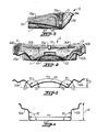
- reference numeral 10 designates the trunk liner as the same substantially appears when removed from the mold. This form of the trunk liner is best illustrated in Figures 1 to 4 of the drawings.
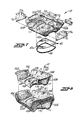
- reference numeral 10 ⁇ designates the completed trunk liner after the same has been suitably trimmed following the molding thereof and after the same has had other components added thereto on the backside, such as insulator pads and a rigid lid underlying a spare tire cover and serving as a cover for covering a spare tire well.
- This completed form of the first embodiment of the trunk liner is best illustrated in Figures 7 to 10 and 13.
- trunk liner For purposes of simplicity, the various elements or features of the completed trunk liner will bear the same reference numerals as the molded but unfinished trunk liner, but with the prime notation added thereto.
- the trunk liner 10 shown as removed from a typical pressure molding operation utilizing mating male and female molding components comprises a center floor cover panel 20 and a plurality of panels extending along the sides of said center floor panel and integrally connected thereto. These panels include a rear end panel 30 having lower end portions connecting rearmost portions of said center floor panel 20 and divergingly extending upwardly and outwardly therefrom.
- Right and left rear wheel housing cover panels 40a and 40b respectively are connected to opposite sides of said center floor cover panel 20 and divergingly extend upwardly and outwardly therefrom.
- Right and left inner panels 50a and 50b respectively are also connected to opposite sides of said center floor cover panel 20 and are divergingly arranged to extend upwardly and outwardly therefrom.
- These right and left inner panels 50 and 50a are positioned rearwardly of the right and left rear wheel housing cover panels 40a, 40b and are respectively connected to rearmost portions of the right and left rear wheel housing cover panels 40a, 40b, respectively.
- the molded trunk liner body 10 is formed of any suitable fibrous material that may readily be subjected to molding. While many textile fibers may be used, polyester staple fibers that have been needle punched or preneedled to form a non-woven fabric have been found to be quite suitable as well as economical to use.
- a moldable coating 11 is applied to the backside of the non-woven fabric and dried prior to being molded. This coating serves to impart shape retention and stiffness to the overall molded body upon the molding operation being completed.
- a relatively lightweight coating of thermoplastic material of a wide variety may be used. However, coatings of polyethylene or moldable latex have each been proven to be suitable, with latex offering the better shape retention. Conventional coating equipment is readily used with either type of coating.
- the upper surface of the trunk liner is desirably formed of soft fibrous material, preferably in the form of pile fibers.
- the back of the body of the trunk liner is relatively hard and rigid to provide the molded memory and shape retention for the trunk liner.
- the desired moldability, stiffness and shape retention properties can be imparted to the trunk liner by other means such as by the composition of the fibrous material itself, as an example, through the use of a web containing heat activatable potentially adhesive fibers.
- One such product is disclosed in commonly owned U.S. Patent 4,568,581.
- the center floor cover panel 20 is provided with an upward bulge or crown thereto, as best illustrated in Figures 3 and 4.
- This bulge or crown serves several purposes. Of primary importance is to prevent the fibrous body from being ruptured when the female and male mold components are moved into mating molding position. In this respect, it will be appreciated that the depth of movement or draw of the fibrous material forming the trunk liner is considerably lessened with this upward bulge being provided in the center floor cover panel 20.
- FIG. 5 schematically illustrates this outwardly diverging relationship by the angles identified as B between the center floor cover panel 20 and the side walls 40a,40b extending therefrom.
- Each angle B is somewhat larger than 90°, and preferably is about 100° to 120°.
- the opposite ends of arc A represent the imaginary position of the sidewall panels if in fact the same were molded at only right angles to the center floor cover panel 20.
- Arc C is about 45° to 55° with arc D being about 25° to 30°.
- the collective arc for angles B, C, and D is 180°.
- This flattening of the center floor cover panel 20 naturally occurs when the panels extending along the sides of the center floor cover panel 20 are biased inwardly toward an upright position when installed in the trunk compartment of an automobile. Further, it will be noted by comparing the molded height H of the trunk liner in Figure 5, with the installed height H ⁇ , of Figure 6, that a considerable increase in overall height of the trunk liner takes place when the trunk liner is installed as compared to the height of the trunk liner when removed from the mold. Further, it has been learned that the crown in the center portion of the center floor cover panel 20 also aids in providing a biasing action to the sides extending outwardly and upwardly from the center floor panel.
- the center floor cover panel 20 has a medial portion thereof defining a spare tire cover indicated by reference numeral 60.
- the periphery of the spare tire cover 60 is defined in the molding operation by providing suitable grooves 63 in the fibrous material. These grooves 63 as best shown in Figures 1 and 2, appear as bulging portions on the rear of the spare tire cover as illustrated in Figures 3 and 4. It will be noted that the grooves 63 take the form of two symetrically arranged opposing arcuate groove segments, each extending from adjacent the rear end panel 30 forwardly across about two-thirds of the center floor cover panel. As will be seen later, as the description proceeds, these grooves 63 will each be cut in the valley thereof so as to free the sides of the spare tire cover from the remainder of the center floor cover panel 20.
- reference numeral 10 ⁇ designates the finished or completed trunk liner after the same has been suitably trimmed following the molding thereof and after insulator pads 70 have been added to predetermined areas of the backside thereof, as well as the providing of a rigid lid 62 underlying the spare tire cover 60 and for covering the spare tire well of the automobile.
- Figures 7 and 8 wherein the prime notation has been added to molded liner elements
- Figures 1 and 2 it will be noted that gusset portions G in Figures 1 and 2, have been removed as by cutting along the dotted lines as indicated. The removal of these gussets G permits the rear end panel 30 ⁇ to be moved substantially to the perpendicular position as when installed, as best shown in Figure 13.
- the removal of the gussets G permits the right and left rear wheel housing cover panels 40a ⁇ 40b ⁇ , and right and left inner panels 50a ⁇ , and 50b ⁇ , to also be moved to the substantially vertical position. Also, since right and left inner panels 50a ⁇ and 50b ⁇ are integrally connected to the right and left rear wheel housing cover panels 40a ⁇ ,40b ⁇ , these inner panels 50a ⁇ ,50b ⁇ may also be moved to the substantially vertical position upon the removal or trimming of the gussets G from the molded liner 10.
- the spare tire cover 60 ⁇ is provided with a multi-piece rigid lid 62 on the backside thereof and which is suitably secured to the cover as by a suitable adhesive such as a heat activatable hot melt adhesive.
- a suitable adhesive such as a heat activatable hot melt adhesive.
- the multi-piece rigid lid 62 takes the form of a relatively small forwardmost piece 62a and a considerably larger rearwardmost piece 62b. As illustrated, these lid pieces 62a,62b are spaced apart from each other and have adjacent parallel edge portions essentially defining a hinge line therebetween for the spare tire cover 60 ⁇ .
- a pull strap 64 is suitably connected as by staples 65 to a substantially central location along the rear periphery of the lid, as illustrated. This is best illustrated in Figures 11, 12, 13 and 15, of the drawings.
- a relatively narrow strip of cushion material 66 is suitably secured as by adhesive, such as hot melt, to the underside of the lid pieces 62a,62b of the lid 62.
- the cushion material 66 may be a fibrous non-woven needle punched material, and is relatively narrow and of about an inch in width to serve this cushioning and insulating function to prevent rattling.
- a plurality of fibrous insulator pads 70 of various thicknesses are secured to the backside of predetermined areas of the plurality of panels extending upwardly and outwardly from the center floor cover panel 60′.
- three rectangular shaped insulator pads 70 are shown secured to the backside of the rear end panel 30 ⁇ and that relatively large quadrant shaped insulator pads 70 are secured to the backside of the right and left rear wheel housing cover panels 40a ⁇ ,40b′.
- these latter insulator pads have notches 70a cut inwardly from the periphery thereof so that the pads may readily be accommodated to the arcuate inner surfaces of the wheel housing cover panels.
- These insulator pads 70 may be secured to the molded trunk liner by any suitable adhesive, which may also be of the hot melt type of adhesive.
- the grooves 63 ⁇ which define the periphery of the spare tire cover are suitably cut, as illustrated, in the bottom of the valley of the grooves.
- the depth of the grooves and the cutting in the valley thereof aids in obscuring the presence of the cut line and imparts continuity to the exposed surface of the trunk liner by shielding the cut line from view.
- the rearmost portion of the spare tire cover 60 ⁇ will not be entirely severed so as to be entirely free from rear end panel 30 ⁇ but will have a pair of spaced uncut portions therebetween which will be severed upon the trunk liner being installed in the automobile.
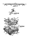
- the trunk liner 10 ⁇ is shown in a condition of being folded upon itself as being installed in the trunk compartment of an automobile.
- opposite sides of the liner, as illustrated, are folded to overlie the spare tire cover to thus reduce the overall width of the trunk liner when being inserted in the opening of the trunk compartment.
- the rigid lid 62 for the spare tire well which underlies the spare tire cover 60 ⁇ , also essentially serves as a carrying platform for the liner, opposite sides of which rigid lid 62 may be gripped by the installer (as illustrated) for facilitating the movement of the trunk liner into the compartment of the trunk.
- the rear end panel 30 ⁇ has a forwardly bulging portion 30a in the upper central portion thereof, and that a slot S is provided therethrough.
- This bulging portion 30a ⁇ accommodates therebehind the latching mechanism for the automobile trunk lid with the slot S serving to permit protrusion therethrough of the loop portion L of the lock, as best illustrated in Figures 11 and 12.
- indentations 30b ⁇ are molded in the rear end panel 30 ⁇ , each of the indentations 30b ⁇ being positioned about half way etween the trunk latch and the opposite ends of the rear end panel 30.
- This second form of the invention basically differs over the first form in two respects, one being the inclusion of a rear seat panel 180 which has lower end portions connected to forwardmost portions of the center floor cover panel 120 ⁇ and extends upwardly and outwardly from the center floor panel in a diverging relationship as best illustrated in Figure 21, where the completed trunk liner is shown ready for shipment.
- this form of the invention avoids the need of separate strip cushion material 66 for insulating the underside of the rigid lid 162 for the spare tire cover well.
- the grooves 163 ⁇ formed along the periphery of the spare tire cover 160 ⁇ are considerably deeper so as to provide sufficient liner material in the groove so as to be turned or folded underneath the peripheral edge portions of the rigid lid 162.
- This feature of the invention is best illustrated in Figures 19 and 20, wherein it will be seen that portions of the spare tire cover material extend underneath the lid 162 adjacent the periphery.
- Suitable means such as staples 190 or hot melt adhesive may be provided for securing the turned under liner material in position on the underside of the lid 162.
- This form of the invention has two pairs of gussets G (not shown) that have been removed in order to permit the side walls 140a ⁇ , 140b ⁇ , 150a ⁇ , 150b ⁇ , 130; and 180 extending upwardly and outwardly from the center floor cover panel 120 to be moved to the substantially vertical position when installed in the trunk compartment of an automobile.
- This positioning of these side panels in the vertica l position as they would appear in the trunk compartment of an automobile, is best illustrated in Figure 18 when comparing the same to the completed trunk liners as nestingly shown in Figure 21.
- both forms of the invention present a one-piece trunk liner having an integral molded, relatively stiff fibrous body having a center floor cover panel and a plurality of panels extending along the sides of center floor cover panel and integrally connected thereto and wherein the panels extend upwardly and outwardly from the center floor cover panel so as to be in outwardly diverging relation to the center floor cover panel.
- the stiffness and shape retention of the molded fibrous body and the outwardly diverging relationship of the plurality of panels cause the panels to resiliently engage and hug the inner wall surfaces of the trunk compartment when the panels are biased inwardly toward an upright position when mounted in the trunk.
- This diverging relationship of the side panels facilitates the mounting of the trunk liner in the trunk of the automobile and further serves to maintain the trunk liner in the installed position in engagement with the walls of the trunk. Further, no longer does the trunk liner take the form of a pieced together jigsaw of a plurality of pieces as in the past, but instead presents an integrally molded trunk liner aesthetically pleasing in appearance and easy to install.
Landscapes
- Engineering & Computer Science (AREA)
- Mechanical Engineering (AREA)
- Vehicle Step Arrangements And Article Storage (AREA)
- Body Structure For Vehicles (AREA)
- Vehicle Interior And Exterior Ornaments, Soundproofing, And Insulation (AREA)
- Adornments (AREA)
Priority Applications (1)
| Application Number | Priority Date | Filing Date | Title |
|---|---|---|---|
| AT87306502T ATE68421T1 (de) | 1986-10-14 | 1987-07-23 | Einteiliger kofferraumeinsatz. |
Applications Claiming Priority (2)
| Application Number | Priority Date | Filing Date | Title |
|---|---|---|---|
| US06/918,515 US4673207A (en) | 1986-10-14 | 1986-10-14 | One-piece automotive trunk liner |
| US918515 | 1986-10-14 |
Publications (2)
| Publication Number | Publication Date |
|---|---|
| EP0266024A1 true EP0266024A1 (de) | 1988-05-04 |
| EP0266024B1 EP0266024B1 (de) | 1991-10-16 |
Family
ID=25440499
Family Applications (1)
| Application Number | Title | Priority Date | Filing Date |
|---|---|---|---|
| EP87306502A Expired - Lifetime EP0266024B1 (de) | 1986-10-14 | 1987-07-23 | Einteiliger Kofferraumeinsatz |
Country Status (8)
| Country | Link |
|---|---|
| US (1) | US4673207A (de) |
| EP (1) | EP0266024B1 (de) |
| JP (1) | JPH0755646B2 (de) |
| KR (1) | KR910001410B1 (de) |
| AT (1) | ATE68421T1 (de) |
| CA (1) | CA1289594C (de) |
| DE (1) | DE3773835D1 (de) |
| ES (1) | ES2027696T3 (de) |
Cited By (7)
| Publication number | Priority date | Publication date | Assignee | Title |
|---|---|---|---|---|
| US5205602A (en) * | 1989-02-09 | 1993-04-27 | B.E.T. Corporation Limited | Motor vehicle boot insert |
| EP0990560A1 (de) * | 1998-09-30 | 2000-04-05 | MAGNA NÄHER GmbH | Kofferraum-Verkleidung sowie Verfahren zu deren Montage |
| WO2000021794A1 (en) * | 1998-10-13 | 2000-04-20 | Neocon International Inc. | Vehicle cargo compartment liner |
| DE10341968A1 (de) * | 2003-09-11 | 2005-04-21 | Volkswagen Ag | Aufnahmevorrichtung für wenigstens ein elektrisches Gerät in einem Kraftfahrzeug |
| RU2301748C1 (ru) * | 2005-11-16 | 2007-06-27 | Алексей Романович Алтухов | Чехол заднего багажника |
| US7798549B2 (en) | 2008-10-30 | 2010-09-21 | Honda Motor Co., Ltd. | Trunk liner method and apparatus |
| DE19746147B4 (de) * | 1996-10-31 | 2010-10-14 | Volkswagen Ag | Gepäckraum in einem Personenkraftwagen |
Families Citing this family (37)
| Publication number | Priority date | Publication date | Assignee | Title |
|---|---|---|---|---|
| USD300524S (en) | 1986-10-28 | 1989-04-04 | Collins & Aikman Corporation | Automobile trunk liner |
| USD301025S (en) | 1986-10-28 | 1989-05-09 | Collins & Aikman Corporation | Automobile trunk liner |
| DE8709743U1 (de) * | 1987-07-15 | 1987-10-01 | Hofmann, Gerhard, 7031 Nufringen | Auskleidungswanne für Kombi- und Personenkraftfahrzeuge |
| USD308036S (en) | 1987-10-23 | 1990-05-22 | Collins & Aikman | Automobile trunk liner |
| US4801169A (en) * | 1988-03-23 | 1989-01-31 | Collins & Aikman Corporation | Automotive trunk liner |
| JPH0342754U (de) * | 1989-08-29 | 1991-04-23 | ||
| US5298319A (en) * | 1992-03-13 | 1994-03-29 | Phillips Petroleum Company | Moldable automotive trunk liner |
| DE4442041A1 (de) * | 1994-11-25 | 1996-05-30 | Naeher Georg Gmbh | Verschluß-/Haltevorrichtung für ein Kfz-Verkleidungsteil |
| US5876090A (en) * | 1997-05-27 | 1999-03-02 | Lear Corporation | Floor covering assembly |
| DE19810714A1 (de) * | 1998-03-12 | 1999-09-30 | Baumeister & Ostler Gmbh Co | Abdeckung für einen Laderaumboden eines Kraftfahrzeugs |
| US6595568B1 (en) * | 2002-11-12 | 2003-07-22 | Daimlerchrysler Corporation | Multi-purpose liner for vehicle compartment |
| US6840559B2 (en) * | 2003-02-14 | 2005-01-11 | Claudio Burtin | Combination truck bed liner |
| US7364224B2 (en) * | 2006-09-29 | 2008-04-29 | Nissan Technical Center North America, Inc. | Combination harness protector and carpet |
| EP2193050B1 (de) * | 2007-09-28 | 2013-04-10 | Lydall, Inc. | Geformte und gebildete schallisolier-fahrzeugplatte und herstellungsverfahren dafür |
| JP5218035B2 (ja) * | 2008-12-26 | 2013-06-26 | トヨタ紡織株式会社 | トランクトリムの取付構造およびその取付方法 |
| FR2969974A1 (fr) * | 2011-01-03 | 2012-07-06 | Peugeot Citroen Automobiles Sa | Dispositif de prehension d'un panneau, tel qu'un tapis ou un plancher de coffre d'un vehicule automobile. |
| US8844993B1 (en) | 2013-09-04 | 2014-09-30 | Nissan North America, Inc. | Reinforced vehicle trim assembly |
| US10005405B2 (en) | 2015-04-28 | 2018-06-26 | Ridge Corporation | Protective liner |
| US9827921B1 (en) | 2017-01-23 | 2017-11-28 | Wallace K. Green | Systems and methods of protecting vehicle cargo areas |
| US12108853B2 (en) | 2019-01-06 | 2024-10-08 | Yeti Coolers, Llc | Luggage system |
| AU201717615S (en) | 2017-06-12 | 2018-01-15 | Yeti Coolers | Container |
| US11976498B2 (en) | 2017-06-12 | 2024-05-07 | Yeti Coolers, Llc | Container and latching system |
| JP7101199B2 (ja) | 2017-06-12 | 2022-07-14 | イエティ クーラーズ エルエルシー | コンテナおよびラッチング・システム |
| US11685573B2 (en) | 2017-06-12 | 2023-06-27 | Yeti Coolers, Llc | Carry strap for container |
| USD862338S1 (en) * | 2017-09-26 | 2019-10-08 | Tesla, Inc. | Front trunk for a vehicle |
| USD907445S1 (en) | 2018-12-11 | 2021-01-12 | Yeti Coolers, Llc | Container accessories |
| USD904829S1 (en) | 2018-12-11 | 2020-12-15 | Yeti Coolers, Llc | Container accessories |
| JP7303313B2 (ja) | 2019-01-06 | 2023-07-04 | イエティ クーラーズ エルエルシー | 荷物システム |
| US12225993B2 (en) | 2019-01-06 | 2025-02-18 | Yeti Coolers, Llc | Luggage system |
| US11214204B2 (en) | 2019-11-25 | 2022-01-04 | Toyota Motor Engineering & Manufacturing North America, Inc. | Multi-function convertible truck cargo bed liner |
| USD951643S1 (en) | 2020-06-30 | 2022-05-17 | Yeti Coolers, Llc | Luggage |
| USD954436S1 (en) | 2020-06-30 | 2022-06-14 | Yeti Coolers, Llc | Luggage |
| USD963344S1 (en) | 2020-06-30 | 2022-09-13 | Yeti Coolers, Llc | Luggage |
| USD961926S1 (en) | 2020-06-30 | 2022-08-30 | Yeti Coolers, Llc | Luggage |
| USD960648S1 (en) | 2020-12-16 | 2022-08-16 | Yeti Coolers, Llc | Container accessory |
| USD994438S1 (en) | 2020-12-16 | 2023-08-08 | Yeti Coolers, Llc | Container |
| USD985937S1 (en) | 2020-12-16 | 2023-05-16 | Yeti Coolers, Llc | Container |
Citations (5)
| Publication number | Priority date | Publication date | Assignee | Title |
|---|---|---|---|---|
| US2911253A (en) * | 1957-01-30 | 1959-11-03 | Raymond J Dewey | Automobile trunk liner |
| GB862378A (en) * | 1957-11-19 | 1961-03-08 | Otto Golze | Luggage boot lining of mechanically propelled vehicles, more particularly for private cars |
| US4568581A (en) * | 1984-09-12 | 1986-02-04 | Collins & Aikman Corporation | Molded three dimensional fibrous surfaced article and method of producing same |
| US4592583A (en) * | 1984-05-08 | 1986-06-03 | Penda Corporation | Truck cargo bed liner |
| US4692583A (en) * | 1985-08-12 | 1987-09-08 | Kabushiki Kaisha Toshiba | Surface heat treating apparatus |
Family Cites Families (6)
| Publication number | Priority date | Publication date | Assignee | Title |
|---|---|---|---|---|
| US2060362A (en) * | 1934-10-29 | 1936-11-10 | John T Zurcher | Dustproof luggage carrier for automobiles |
| US2912137A (en) * | 1956-04-09 | 1959-11-10 | Diamond Alkali Co | Liner for container |
| US4279439A (en) * | 1979-09-14 | 1981-07-21 | Cantieri Thomas B | Molded liner for pickup trucks |
| JPS5823782U (ja) * | 1981-08-08 | 1983-02-15 | 河西工業株式会社 | トランクル−ムトリムにおけるスペアタイヤカバ− |
| JPS5828371A (ja) * | 1981-08-12 | 1983-02-19 | 日産自動車株式会社 | 車両のトランクル−ム内装材 |
| JPS5836737A (ja) * | 1981-10-09 | 1983-03-03 | Nissan Motor Co Ltd | トランクル−ムトリム |
-
1986
- 1986-10-14 US US06/918,515 patent/US4673207A/en not_active Ceased
-
1987
- 1987-06-25 CA CA000540523A patent/CA1289594C/en not_active Expired - Fee Related
- 1987-07-15 JP JP62176946A patent/JPH0755646B2/ja not_active Expired - Lifetime
- 1987-07-23 DE DE8787306502T patent/DE3773835D1/de not_active Expired - Lifetime
- 1987-07-23 AT AT87306502T patent/ATE68421T1/de not_active IP Right Cessation
- 1987-07-23 ES ES198787306502T patent/ES2027696T3/es not_active Expired - Lifetime
- 1987-07-23 EP EP87306502A patent/EP0266024B1/de not_active Expired - Lifetime
- 1987-10-14 KR KR1019870011410A patent/KR910001410B1/ko not_active Expired
Patent Citations (5)
| Publication number | Priority date | Publication date | Assignee | Title |
|---|---|---|---|---|
| US2911253A (en) * | 1957-01-30 | 1959-11-03 | Raymond J Dewey | Automobile trunk liner |
| GB862378A (en) * | 1957-11-19 | 1961-03-08 | Otto Golze | Luggage boot lining of mechanically propelled vehicles, more particularly for private cars |
| US4592583A (en) * | 1984-05-08 | 1986-06-03 | Penda Corporation | Truck cargo bed liner |
| US4568581A (en) * | 1984-09-12 | 1986-02-04 | Collins & Aikman Corporation | Molded three dimensional fibrous surfaced article and method of producing same |
| US4692583A (en) * | 1985-08-12 | 1987-09-08 | Kabushiki Kaisha Toshiba | Surface heat treating apparatus |
Non-Patent Citations (2)
| Title |
|---|
| PATENT ABSTRACTS OF JAPAN, vol. 7, no. 116 (M-216)[1261], 20th May 1983; & JP-A-58 36 738 (NISSAN JIDOSHA K.K.) 03-03-1983 * |
| PATENT ABSTRACTS OF JAPAN, vol. 7, no. 116 (M-216)[1261], 20th May 1983; JP-A-58 36 737 (NISSAN JIDOSHA K.K.) 03-03-1983 * |
Cited By (7)
| Publication number | Priority date | Publication date | Assignee | Title |
|---|---|---|---|---|
| US5205602A (en) * | 1989-02-09 | 1993-04-27 | B.E.T. Corporation Limited | Motor vehicle boot insert |
| DE19746147B4 (de) * | 1996-10-31 | 2010-10-14 | Volkswagen Ag | Gepäckraum in einem Personenkraftwagen |
| EP0990560A1 (de) * | 1998-09-30 | 2000-04-05 | MAGNA NÄHER GmbH | Kofferraum-Verkleidung sowie Verfahren zu deren Montage |
| WO2000021794A1 (en) * | 1998-10-13 | 2000-04-20 | Neocon International Inc. | Vehicle cargo compartment liner |
| DE10341968A1 (de) * | 2003-09-11 | 2005-04-21 | Volkswagen Ag | Aufnahmevorrichtung für wenigstens ein elektrisches Gerät in einem Kraftfahrzeug |
| RU2301748C1 (ru) * | 2005-11-16 | 2007-06-27 | Алексей Романович Алтухов | Чехол заднего багажника |
| US7798549B2 (en) | 2008-10-30 | 2010-09-21 | Honda Motor Co., Ltd. | Trunk liner method and apparatus |
Also Published As
| Publication number | Publication date |
|---|---|
| KR910001410B1 (ko) | 1991-03-05 |
| ATE68421T1 (de) | 1991-11-15 |
| JPS6397446A (ja) | 1988-04-28 |
| US4673207A (en) | 1987-06-16 |
| KR880004982A (ko) | 1988-06-27 |
| EP0266024B1 (de) | 1991-10-16 |
| CA1289594C (en) | 1991-09-24 |
| DE3773835D1 (de) | 1991-11-21 |
| JPH0755646B2 (ja) | 1995-06-14 |
| ES2027696T3 (es) | 1992-06-16 |
Similar Documents
| Publication | Publication Date | Title |
|---|---|---|
| EP0266024B1 (de) | Einteiliger Kofferraumeinsatz | |
| USRE33200E (en) | One-piece automotive trunk liner | |
| CA1294650C (en) | Automotive trunk liner | |
| US6986541B1 (en) | Truck bed liner with storage compartment | |
| US6015178A (en) | Truck bed liner with hingedly affixed divider | |
| US4890883A (en) | Upholstery system | |
| US5378014A (en) | Dual door arrangement for air bag deployment | |
| US4867500A (en) | Vehicle armrest | |
| USD1099800S1 (en) | Front portion for a motor vehicle | |
| US4883139A (en) | Winter front for the grill of a motor vehicle | |
| USD313964S (en) | Automobile passenger compartment cover | |
| EP0960782B1 (de) | Zierleiste für Kraftfahrzeuge und Verfahren zu ihrer Herstellung | |
| JP2000108793A (ja) | 車両後部構造 | |
| US5829778A (en) | Air bag restraint system | |
| USD1098977S1 (en) | Front bumper lower garnish for automobile | |
| USRE34333E (en) | Upholstery system | |
| USD402832S (en) | Head rest for an integrated child car seat | |
| JP3265955B2 (ja) | トリム部品におけるリッドの係止構造 | |
| JP2519479Y2 (ja) | フロアリッド体 | |
| JPH0133382Y2 (de) | ||
| JPS5826654A (ja) | 自動車のリア−パ−セルおよびその成形方法 | |
| JPS6238829Y2 (de) | ||
| JPH1058974A (ja) | 自動車用ドアトリム | |
| JPH0641885Y2 (ja) | トランクルームトリムの取付構造 | |
| JPH0458453U (de) |
Legal Events
| Date | Code | Title | Description |
|---|---|---|---|
| PUAI | Public reference made under article 153(3) epc to a published international application that has entered the european phase |
Free format text: ORIGINAL CODE: 0009012 |
|
| AK | Designated contracting states |
Kind code of ref document: A1 Designated state(s): AT BE CH DE ES FR GB GR IT LI LU NL SE |
|
| 17P | Request for examination filed |
Effective date: 19881028 |
|
| 17Q | First examination report despatched |
Effective date: 19900530 |
|
| GRAA | (expected) grant |
Free format text: ORIGINAL CODE: 0009210 |
|
| AK | Designated contracting states |
Kind code of ref document: B1 Designated state(s): AT BE CH DE ES FR GB GR IT LI LU NL SE |
|
| PG25 | Lapsed in a contracting state [announced via postgrant information from national office to epo] |
Ref country code: LI Effective date: 19911016 Ref country code: GR Free format text: LAPSE BECAUSE OF FAILURE TO SUBMIT A TRANSLATION OF THE DESCRIPTION OR TO PAY THE FEE WITHIN THE PRESCRIBED TIME-LIMIT Effective date: 19911016 Ref country code: CH Effective date: 19911016 Ref country code: BE Effective date: 19911016 |
|
| REF | Corresponds to: |
Ref document number: 68421 Country of ref document: AT Date of ref document: 19911115 Kind code of ref document: T |
|
| REF | Corresponds to: |
Ref document number: 3773835 Country of ref document: DE Date of ref document: 19911121 |
|
| ITF | It: translation for a ep patent filed | ||
| REG | Reference to a national code |
Ref country code: CH Ref legal event code: PL |
|
| ET | Fr: translation filed | ||
| PLBI | Opposition filed |
Free format text: ORIGINAL CODE: 0009260 |
|
| PG25 | Lapsed in a contracting state [announced via postgrant information from national office to epo] |
Ref country code: LU Free format text: LAPSE BECAUSE OF NON-PAYMENT OF DUE FEES Effective date: 19920731 |
|
| 26 | Opposition filed |
Opponent name: JOHANN BORGERS GMBH & CO. KG. Effective date: 19920714 |
|
| NLR1 | Nl: opposition has been filed with the epo |
Opponent name: JOHANN BORGERS GMBH & CO. KG. |
|
| PLBM | Termination of opposition procedure: date of legal effect published |
Free format text: ORIGINAL CODE: 0009276 |
|
| STAA | Information on the status of an ep patent application or granted ep patent |
Free format text: STATUS: OPPOSITION PROCEDURE CLOSED |
|
| 27C | Opposition proceedings terminated |
Effective date: 19930528 |
|
| NLR2 | Nl: decision of opposition | ||
| PGFP | Annual fee paid to national office [announced via postgrant information from national office to epo] |
Ref country code: GB Payment date: 19940712 Year of fee payment: 8 |
|
| PGFP | Annual fee paid to national office [announced via postgrant information from national office to epo] |
Ref country code: FR Payment date: 19940715 Year of fee payment: 8 |
|
| PGFP | Annual fee paid to national office [announced via postgrant information from national office to epo] |
Ref country code: DE Payment date: 19940716 Year of fee payment: 8 |
|
| PGFP | Annual fee paid to national office [announced via postgrant information from national office to epo] |
Ref country code: ES Payment date: 19940718 Year of fee payment: 8 |
|
| PGFP | Annual fee paid to national office [announced via postgrant information from national office to epo] |
Ref country code: AT Payment date: 19940729 Year of fee payment: 8 |
|
| PGFP | Annual fee paid to national office [announced via postgrant information from national office to epo] |
Ref country code: SE Payment date: 19940731 Year of fee payment: 8 Ref country code: NL Payment date: 19940731 Year of fee payment: 8 |
|
| EAL | Se: european patent in force in sweden |
Ref document number: 87306502.3 |
|
| ITPR | It: changes in ownership of a european patent |
Owner name: CAMBIO RAGIONE SOCIA;COLLINS & AIKMAN PRODUCTS CO. |
|
| REG | Reference to a national code |
Ref country code: FR Ref legal event code: CD Ref country code: FR Ref legal event code: CA |
|
| REG | Reference to a national code |
Ref country code: ES Ref legal event code: PC2A Owner name: COLLINS & AIKMAN PRODUCTS CO. |
|
| NLT1 | Nl: modifications of names registered in virtue of documents presented to the patent office pursuant to art. 16 a, paragraph 1 |
Owner name: COLLINS & AIKMAN PRODUCTS CO. TE NEW YORK, NEW YOR |
|
| PG25 | Lapsed in a contracting state [announced via postgrant information from national office to epo] |
Ref country code: GB Effective date: 19950723 Ref country code: AT Effective date: 19950723 |
|
| PG25 | Lapsed in a contracting state [announced via postgrant information from national office to epo] |
Ref country code: SE Effective date: 19950724 Ref country code: ES Free format text: LAPSE BECAUSE OF EXPIRATION OF PROTECTION Effective date: 19950724 |
|
| PG25 | Lapsed in a contracting state [announced via postgrant information from national office to epo] |
Ref country code: NL Effective date: 19960201 |
|
| GBPC | Gb: european patent ceased through non-payment of renewal fee |
Effective date: 19950723 |
|
| NLV4 | Nl: lapsed or anulled due to non-payment of the annual fee |
Effective date: 19960201 |
|
| PG25 | Lapsed in a contracting state [announced via postgrant information from national office to epo] |
Ref country code: DE Effective date: 19960402 |
|
| EUG | Se: european patent has lapsed |
Ref document number: 87306502.3 |
|
| PG25 | Lapsed in a contracting state [announced via postgrant information from national office to epo] |
Ref country code: FR Effective date: 19960430 |
|
| REG | Reference to a national code |
Ref country code: FR Ref legal event code: ST |
|
| REG | Reference to a national code |
Ref country code: FR Ref legal event code: ST |
|
| REG | Reference to a national code |
Ref country code: FR Ref legal event code: ST |
|
| REG | Reference to a national code |
Ref country code: ES Ref legal event code: FD2A Effective date: 19990601 |
|
| PG25 | Lapsed in a contracting state [announced via postgrant information from national office to epo] |
Ref country code: IT Free format text: LAPSE BECAUSE OF NON-PAYMENT OF DUE FEES Effective date: 20050723 |