EP0312216B1 - Dispositif de commande de soupape pour moteur à combustion interne - Google Patents
Dispositif de commande de soupape pour moteur à combustion interne Download PDFInfo
- Publication number
- EP0312216B1 EP0312216B1 EP88308814A EP88308814A EP0312216B1 EP 0312216 B1 EP0312216 B1 EP 0312216B1 EP 88308814 A EP88308814 A EP 88308814A EP 88308814 A EP88308814 A EP 88308814A EP 0312216 B1 EP0312216 B1 EP 0312216B1
- Authority
- EP
- European Patent Office
- Prior art keywords
- valve
- rocker arm
- internal combustion
- control system
- operation control
- Prior art date
- Legal status (The legal status is an assumption and is not a legal conclusion. Google has not performed a legal analysis and makes no representation as to the accuracy of the status listed.)
- Expired - Lifetime
Links
- 238000002485 combustion reaction Methods 0.000 title claims description 43
- 230000007246 mechanism Effects 0.000 claims description 89
- 230000003139 buffering effect Effects 0.000 claims description 11
- 230000001747 exhibiting effect Effects 0.000 claims description 3
- 238000006073 displacement reaction Methods 0.000 claims 1
- 239000003921 oil Substances 0.000 description 16
- 230000000717 retained effect Effects 0.000 description 10
- 230000000694 effects Effects 0.000 description 9
- 210000000078 claw Anatomy 0.000 description 6
- 230000005284 excitation Effects 0.000 description 6
- 239000002184 metal Substances 0.000 description 4
- 239000000203 mixture Substances 0.000 description 4
- 230000006835 compression Effects 0.000 description 3
- 238000007906 compression Methods 0.000 description 3
- 238000010276 construction Methods 0.000 description 3
- 230000002401 inhibitory effect Effects 0.000 description 3
- 230000002093 peripheral effect Effects 0.000 description 3
- 230000000903 blocking effect Effects 0.000 description 2
- 239000011435 rock Substances 0.000 description 2
- 230000004323 axial length Effects 0.000 description 1
- 238000013016 damping Methods 0.000 description 1
- 238000001514 detection method Methods 0.000 description 1
- 239000000446 fuel Substances 0.000 description 1
- 230000001050 lubricating effect Effects 0.000 description 1
- 239000010687 lubricating oil Substances 0.000 description 1
- 230000035939 shock Effects 0.000 description 1
Images














Classifications
-
- F—MECHANICAL ENGINEERING; LIGHTING; HEATING; WEAPONS; BLASTING
- F01—MACHINES OR ENGINES IN GENERAL; ENGINE PLANTS IN GENERAL; STEAM ENGINES
- F01L—CYCLICALLY OPERATING VALVES FOR MACHINES OR ENGINES
- F01L1/00—Valve-gear or valve arrangements, e.g. lift-valve gear
- F01L1/12—Transmitting gear between valve drive and valve
- F01L1/14—Tappets; Push rods
- F01L1/143—Tappets; Push rods for use with overhead camshafts
-
- F—MECHANICAL ENGINEERING; LIGHTING; HEATING; WEAPONS; BLASTING
- F01—MACHINES OR ENGINES IN GENERAL; ENGINE PLANTS IN GENERAL; STEAM ENGINES
- F01L—CYCLICALLY OPERATING VALVES FOR MACHINES OR ENGINES
- F01L1/00—Valve-gear or valve arrangements, e.g. lift-valve gear
- F01L1/12—Transmitting gear between valve drive and valve
- F01L1/14—Tappets; Push rods
- F01L1/16—Silencing impact; Reducing wear
-
- F—MECHANICAL ENGINEERING; LIGHTING; HEATING; WEAPONS; BLASTING
- F01—MACHINES OR ENGINES IN GENERAL; ENGINE PLANTS IN GENERAL; STEAM ENGINES
- F01L—CYCLICALLY OPERATING VALVES FOR MACHINES OR ENGINES
- F01L1/00—Valve-gear or valve arrangements, e.g. lift-valve gear
- F01L1/12—Transmitting gear between valve drive and valve
- F01L1/18—Rocking arms or levers
- F01L1/181—Centre pivot rocking arms
-
- F—MECHANICAL ENGINEERING; LIGHTING; HEATING; WEAPONS; BLASTING
- F01—MACHINES OR ENGINES IN GENERAL; ENGINE PLANTS IN GENERAL; STEAM ENGINES
- F01L—CYCLICALLY OPERATING VALVES FOR MACHINES OR ENGINES
- F01L13/00—Modifications of valve-gear to facilitate reversing, braking, starting, changing compression ratio, or other specific operations
-
- F—MECHANICAL ENGINEERING; LIGHTING; HEATING; WEAPONS; BLASTING
- F01—MACHINES OR ENGINES IN GENERAL; ENGINE PLANTS IN GENERAL; STEAM ENGINES
- F01L—CYCLICALLY OPERATING VALVES FOR MACHINES OR ENGINES
- F01L13/00—Modifications of valve-gear to facilitate reversing, braking, starting, changing compression ratio, or other specific operations
- F01L13/0015—Modifications of valve-gear to facilitate reversing, braking, starting, changing compression ratio, or other specific operations for optimising engine performances by modifying valve lift according to various working parameters, e.g. rotational speed, load, torque
- F01L13/0031—Modifications of valve-gear to facilitate reversing, braking, starting, changing compression ratio, or other specific operations for optimising engine performances by modifying valve lift according to various working parameters, e.g. rotational speed, load, torque by modification of tappet or pushrod length
-
- F—MECHANICAL ENGINEERING; LIGHTING; HEATING; WEAPONS; BLASTING
- F01—MACHINES OR ENGINES IN GENERAL; ENGINE PLANTS IN GENERAL; STEAM ENGINES
- F01L—CYCLICALLY OPERATING VALVES FOR MACHINES OR ENGINES
- F01L9/00—Valve-gear or valve arrangements actuated non-mechanically
- F01L9/20—Valve-gear or valve arrangements actuated non-mechanically by electric means
-
- F—MECHANICAL ENGINEERING; LIGHTING; HEATING; WEAPONS; BLASTING
- F02—COMBUSTION ENGINES; HOT-GAS OR COMBUSTION-PRODUCT ENGINE PLANTS
- F02B—INTERNAL-COMBUSTION PISTON ENGINES; COMBUSTION ENGINES IN GENERAL
- F02B2275/00—Other engines, components or details, not provided for in other groups of this subclass
- F02B2275/18—DOHC [Double overhead camshaft]
Definitions
- the present invention relates to a valve operation control system in an internal combustion engine, comprising an engine valve openably and closably supported on an engine body, a valve spring for biasing the engine valve in a valve-closing direction, and valve driving means interposed between a valve-operating cam and the engine valve to transmit a force in the valve-opening direction provided by the valve-operating cam to the engine valve.
- valve operation control system which provides controlling of opening and closing an intake valve or an exhaust valve as an engine valve not only by the coaction of a valve-operating cam and a valve spring but also by the operation of an electromagnetic actuator depending upon the operational state of an engine.
- the present applicant has proposed an engine valve-opening and -closing operation control system of the type described above (Japanese Patent Application No.123647/87) in which an attractive force of an electromagnetic actuator is utilized at a maximum to provide an improvement in performance of an engine.
- Japanese Patent Application No.123647/87 Japanese Patent Application No.123647/87
- the system is accompanied by a problem that a valve-closing timing can be controlled, but is impossible to provide a variable control of valve-opening timing where an inertial supercharging can be put to practical use, because the engine valve is opened by excitation of the electromagnetic actuator and closed by a spring force as a result of releasing of such excitation.
- FR-A-373509 discloses a valve operation control system in an internal combustion engine, comprising an engine valve openably and closably supported on an engine body, valve spring means for biasing said engine valve in a valve-closing direction, and valve driving means interposed between a valve-operating cam and the engine valve to transmit a force in the valve-opening direction provided by the valve-operating cam to the engine valve, wherein said valve driving means is provided with a valve-opening resilient member for exhibiting a repulsive force in a direction to open said engine valve, and said system includes closed-position retaining means interposed between said engine valve and said valve operating cam for retaining the engine valve in its closed position, with any valve-opening force provided by the valve-operating cam being accumulated by the valve-opening resilient member, said closed-position retaining means being arranged to be switchable between a retaining state and a releasing state to control the timing of opening said engine valve depending upon the operational condition of the engine.
- the present invention is characterised in that the repulsive force provided by the valve-opening resilient member is arranged to be greater than the biasing force of the valve spring means and to oppose said biasing force to cause opening of said engine valve.
- controlling of the timing of releasing the retaining of the closed position by the closed-position retaining means makes it possible to set a valve-opening timing most suitable for any operational state of the engine, thereby improving the intake or exhaust inertial effect to increase the intake or exhaust efficiency.
- a combustion chamber 2 and an intake port 3 communicating with the combustion chamber 2 are defined in a cylinder head 1 of an engine body E.
- the intake port 3 is connected to an intake system including a fuel feeder 4.
- the cylinder head 1 is provided with an intake valve 5 serving as an engine valve adapted to open and close an opened end of the intake port 3 which is closer to the combustion chamber 2.
- the intake valve 5 is comprised of a valve stem 5a and a valve plug 5b.
- the valve stem 5a is slidably received in a valve guide 6 secured to the cylinder head 1, while the valve plug 5b is adapted to seat on a valve seat 7 at the opened end of the intake port 3 closer to the combustion chamber 2, from the side of the combustion chamber 2.
- a spring retainer 9 is mounted on an upper end of the valve stem 5a through a cotter 8.
- Valve springs 11 and 12 each comprising a compression coiled spring are provided in compression between the spring retainer 9 and a spring seat 10 formed on the cylinder head 1 in a facing relation to the spring retainer 9, so that repulsive forces of the valve springs 11 and 12 bias the intake valve 5 in a closing direction.
- the spring retainer 9 is formed of a magnetic element and constructs an electromagnetic actuator A1 as closed-position retaining means by cooperation with an electromagnet 13 which will be described hereinafter.
- a valve-operating cam shaft 14 operatively connected to a crank shaft (not shown) is rotatably carried on a cam holder (not shown) provided on the cylinder head 1.
- Valve driving means 16 is interposed between an intake cam 15 as a valve-operating cam integrally formed on the valve-operating cam shaft 14 and the intake valve 5 for transmitting a force in an opening direction provided by the intake cam 15 to the intake valve 5.
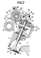
- the valve driving means 16 comprises a rocker shaft 17 fixedly disposed in parallel to and above the valve-operating cam 15 between the valve-operating cam shaft 14 and the intake valve 5, a first rocker arm 18 carried on the rocker shaft 17 to rock insliding contact with the intake cam 15, a second rocker arm 19 carried on the rocker shaft 17 to rock while abutting against an upper end of the intake valve 5, and torsion springs 20 as valve-opening resilient members interposed between both the rocker arms 18 and 19 to exhibit a spring force in a direction to open the intake valve 5.
- a collar 22 is mounted on the rocker shaft 17 through a cylindrical slide metal 21.
- the collar 22 is basically shaped into a cylindrical form, and retaining rings 23 are fitted in the slide metal 21 to abut against opposite ends of the collar 22, respectively.
- the collar 22 is provided at its axially opposite ends with drum portions 22a around which the torsion springs 20 are wound, and the first and second rocker arms 18 and 19 are rotatably supported at their base ends on a portion of the collar 22 axially closer to its central portion, i.e., between both the drum portions 22a.
- the first rocker arm 18 is disposed to extend from the rocker shaft 17 toward the intake cam 15, and a cam surface of the intake cam 15 is in slide contact with a lower surface at a leading end of the first rocker arm 18.
- the second rocker arm 19 is disposed to extend from the rocker shaft 17 toward the intake valve 5 with its base portion being in slide contact with a base portion of the first rocker arm 18.
- a tappet screw 24 is threadedly fitted for advancing and retreating movements in a leading end of the second rocker arm 19 to abut against the upper end of the valve stem 5a of the intake valve 5.
- a lock nut 25 abutting against an upper surface at the leading end of the second rocker arm 19 is threadedly fitted over the tappet screw 24 to maintain an adjusted advance or retreat position.
- Locking pins 26 and 27 parallel to the rocker shaft 17 are secured to the first and second rocker arms 18 and 19 to project oppositely sideways, respectively.
- Each of the torsion springs 20 is wound around the corresponding drum portion 22a of the collar 22 and is engaged at one end with the locking pin 26 of the first rocker arm 18, and at the other end is engaged with the locking pin 27 of the second rocker arm 19.
- This allows the first and second rocker arms 18 and 19 to be biased, so that the first rocker arm 18 is swung toward the intake cam 15, and the second rocker arm 19 is swung toward the intake valve 5.
- the repulsive forces of the torsion springs 20 are set to be larger than those of the valve springs 11 and 12.
- the annular electromagnet 13 is secured to the cylinder head 1 in an opposed relation to an upper surface of the spring retainer 9 to surround the valve stem 5a of the intake valve 5 and constructs the electromagnetic actuator A1 by cooperation with the magnetic element 9 serving as the spring retainer.
- the electromagnet 13 is perforated with a through hole 30 which comprises a smaller diameter hole portion 28 whose wall is in sliding contact with the valve stem 5a of the intake valve 5 and which is coaxially connected to a larger diameter hole portion 29 larger in diameter than the smaller diameter hole portion 28.
- the valve stem 5a of the intake valve 5 is inserted through the hole 30 for movement in an axial direction.
- Excitation of a solenoid in the electromagnet 13 causes the magnetic element 9 to be attracted to the electromagnetic 13.
- the attractive force of the electromagnetic actuator A1 and the spring forces of the valve springs 11 and 12 are set to be larger than the repulsive forces of the torsion springs 20 of the valve driving means 16.
- a damper mechanism D1 for moderating the sudden valve-opening operation of the intake valve 5 is provided between the intake valve 5 and the electromagnet 13 as a guide member for guiding the operation of the intake valve 5.
- the damper mechanism D1 comprises a hydraulic chamber 34 in hole 30 around valve stem 5a between a stepped portion 32a provided at the upper end of the intake valve 5 and the electromagnet 13. More specifically, a cap-like valve piece 32 is fitted over the upper end of the valve stem 5a inserted through the hole 30 and is slidably received into the larger diameter hole portion 29 of the through hole 30.
- the hydraulic chamber 34 is defined between the stepped portion 32a provided by the cap-like valve piece 32 and a stepped portion 30a formed between the smaller diameter hole portion 28 and the larger diameter hole portion 29.
- An annular recess 31 is provided on an inner surface at an intermediate portion of the larger diameter hole portion 29 in the through hole 30, and the electromagnet 13 is provided with an oil feed hole 33 leading to the annular recess 31 and connected to an oil supply source which is not shown.
- the valve piece 32 is fitted over the valve stem 5a in such a manner that an upper portion of the valve piece 32 projects upwardly from an upper end of the through hole 30 when the intake valve 5 is in its closed position, and the tappet screw 24 abuts against the valve piece 32.
- a lock mechanism R1 is provided between the first and second rocker arms 18 and 19 in the valve driving means 16.
- the lock mechanism R1 is capable of blocking the relative swinging movement of the rocker arms 18 and 19 against the spring forces of the torsion springs 20 and comprises a locking member 51 slidably fitted in the second rocker arm 19, a hydraulic chamber 52 provided in the second rocker arm 19 to face the back of the locking member 51 in order to exhibit a hydraulic pressure for bringing the locking member 51 into abutment against the first rocker arm 18, and a return spring 53 for biasing the locking member 51 in a direction to contact the hydraulic chamber 52.
- the second rocker arm 19 is provided with a bottomed slide hole 54 opened to the first rocker arm 18, and a double cylinder-like spring receiving member 55 is fitted in an opened end of the slide hole 54.
- the locking member 51 slidably received in the slide hole 54 can be guided by the spring receiving member 55 to project from the second rocker arm 19 in a direction to abut against the first rocker arm 18.
- the return spring 53 is compressed between the spring receiving member 55 and the locking member 51.
- the hydraulic chamber 52 is defined between the locking member 51 and a closed end of the slide hole 54 and communicates with a passage 56 made in the second rocker arm 19.
- the passage 56 is normally in communication with a hydraulic pressure supply passage 57 provided in the rocker shaft 17 through the collar 22 and the slide metal 21, and the hydraulic pressure supply passage 57 is connected to a hydraulic pressure supply source which is not shown.
- a control circuit C is connected to the solenoid of the electromagnet 13 and adapted to operate and sense the operative conditions of the engine, so that energization and deenergization of the electromagnet 13 are controlled in change-over by a signal from the control circuit C. Detection signals are applied to the control circuit C, such as the number of revolutions of engine, the temperature, the degree of opening of a throttle and the amount of air drawn as signals for detecting the operative conditions of the engine.
- the intake valve 5 is driven to be opened and closed with a predetermined timing by coaction of the intake cam 15 and the valve springs 11 and 12.
- the amount of lift of the intake valve 5 opened relative to the angle of rotation of the valve-operating cam shaft 14 describes a lift curve as indicated by a one-dot chain line in Fig.5.
- the electromagnet 13 is energized under a control by the control circuit, so that the magnetic element 9 is attracted to the electromagnet 13, while a circular base portion of the intake cam 15 is in slide contact with the first rocker arm 18, i.e., before the intake valve 5 is in a lifted state.
- the electromagnet 13 is deenergized under a control by the control circuit C when the valve-operating cam shaft 14 continues to rotate, so that the angle of rotation reaches, for example, near a point P in Fig.5, i.e., a point just short of the amount of lift provided by the intake cam 15 becoming a maximum, the force of attraction by the magnetic element 9 is released.
- the valve piece 32 in the damper mechanism D1 Upon releasing of the state retained by the electromagnetic actuator A1, the valve piece 32 in the damper mechanism D1 is moved downwardly within the through hole 30 in the electromagnet 13, and when the distance l between the stepped portions 32a and 30a (see Fig.3) becomes zero, so that the valve piece 32 is fitted into a lower portion of the larger diameter hole portion 29, the hydraulic pressure is confined into the hydraulic chamber 34 between the stepped portions 32a and 30a. Therefore, the rate the valve piece 32 moves downwardly, i.e., the rate of intake valve 5 opening is moderated, so that the intake valve 5 is slowly opened, as the confined hydraulic pressure gradually leaks from between the valve piece 32 and the smaller diameter hole portion 28. In this manner, a shockingly opening operation of the intake valve 5 is moderated.
- the intake valve 5 is opened in a usual lift curve by coaction of the intake cam 15 and the valve springs 11 and 12.
- valve-operating cam shaft 14 is not disposed just above the intake valve 5 and hence, it is also possible to avoid the increase in entire height due to the disposition of the valve-operating cam shaft 14 at a location over the intake valve 5.
- valve-closure retaining operation of the electromagnetic actuator A1 can be effected with any timing as indicated by a thin line in Fig. 5 irrespective of the operating conditions of the engine.
- the valve-opening timing can be varied at any point between from a point just after start of lifting of the cam to a point of the maximum lift as well as between from the point of the maximum lift to a point just before completion of lifting of the cam.
- the energization of the electromagnetic actuator A1 is normally interrupted, there are obtained opening and closing timings generally in alignment with the cam profile.
- the energization of the electromagnetic actuator A1 is continued during lifting of the cam, it is possible to provide the inoperative state of the valve.
- the electromagnetic actuator A1 When the engine has a high load operating condition, the electromagnetic actuator A1 is deenergized, and a hydraulic pressure is supplied into the hydraulic chamber 52 in the lock mechanism R1. By doing so, the locking member 51 abuts against the first rocker arm 18, thereby blocking the relative swinging movements of the rocker arms 18 and 19 normally resisted only by the repulsive forces of the torsion springs 20. Accordingly, even though the torsion springs 20 are interposed in the valve driving means 16, it is possible to permit the second rocker arm 19 to follow the first rocker arm 18 directly, while inhibiting the resilient operation of the torsion springs 20, and thus, the intake valve 5 can be driven to be opened and closed without change of the profile of the intake cam 15.
- Fig.8 illustrates a second embodiment wherein a damper mechanism D2 is provided between the first and second rocker arms 18 and 19 in the valve driving means 16.
- the damper mechanism D2 comprises a piston 58 slidably received in the second rocker arm 19, and a hydraulic chamber 59 defined to face the back of the piston 58 in order to exhibit a hydraulic pressure for forcing the piston 58 into abutment against the first rocker arm 18.
- the first rocker arm 18 is provided with an abutment arm 60 projecting therefrom and adapted to be close to the second rocker arm 19 when the both rocker arms 18 and 19 are swung by the repulsive forces of the torsion springs 20 (see Fig.1), and the second rocker arm 19 is provided with a slide hole 61 opened in an opposed relation to the abutment arm 60.
- a bottomed cylindrical slide member 62 is received in the slide hole 61, and the piston 58 is received in the slide member 62 for sliding movement relative to each other.
- the hydraulic chamber 59 is defined between the piston 58 and the slide member 62 and communicates with the interior of the slide hole 61 through a restriction orifice 63 provided at a closed end of the slide member 62.
- a valve bore 64 is also made in the closed end of the slide member 62 in parallel to the restriction orifice 63. Contained in the hydraulic chamber 59 are a valve ball 65 capable of opening and closing the valve bore 64, and a spring 66 for biasing the valve ball 65 to close the valve bore.
- the second rocker arm 19 is perforated with a passage 67 communicating with the slide hole 61 and also normally communicating with a hydraulic pressure supply passage 57 provided in the rocker shaft 17 through the collar 22 and the slide metal 21.
- An accumulator 68 is disposed in the second rocker arm 19 to face the passage 67.
- the rate of intake valve 5 opening is moderated by the damper mechanism D2. More specifically, in the damper mechanism D2, as the hydraulic pressure within the hydraulic chamber 59 is gradually discharged through the restriction orifice 63, the second rocker arm 19 is swung in a valve-opening direction, thereby moderating the action of the second rocker arm 19 in the valve-opening direction.
- the damper mechanism D2 is combined with the damper mechanism D1 of the previous first embodiment, the total effect of buffering the rate of valve opening is more effective.
- a buffering effect is exhibited from the time when the distance between the stepped portions 32a and 30a has become zero as shown in Fig.3. This is in the situation where the energy released from the torsion springs 20 is larger in the vicinity of a position in which the amount of lift of the intake valve 5 becomes the maximum.
- the damper mechanism D2 a buffering effect is being exhibited all the time while the intake valve 5 is in operation of opening the valve.
- Fig.9 illustrates a third embodiment of the present invention, wherein a damper mechanism D3 is provided at an impulse contact portion between the first and second rocker arms 18 and 19.
- the damper mechanism D3 comprises a piston 69 slidably received in the second rocker arm 19, and a hydraulic chamber 70 defined to face a back of the piston 69 in order to exhibit a hydraulic pressure for forcing the piston 69 into abutment against the first rocker arm 18.
- the second rocker arm 19 is provided with a slide hole 61 opened in an opposed relation to an abutment arm 60 of the first rocker arm 18.
- the bottomed cylindrical piston 69 is slidably received in the slide hole 61, and a cylindrical slide member 71 is received in the piston 69 for sliding movement relative to each other.
- the hydraulic chamber 70 is defined between the piston 69 and the slide member 71 and communicates with the interior of the slide hole 61 through a clearance provided between the piston 69 and the slide member 71.
- a valve bore 72 is also made in the slide member 71.
- the hydraulic chamber 70 containes therein a valve ball 73 capable of opening and closing the valve bore 72 and a spring 74 for biasing the valve ball 73 to close the valve bore.
- the slide member 71 is biased in a direction to fit into the piston 69 by a spring 75 interposed between the slide member 71 and the second rocker arm 19.
- the slide hole 61 normally communicates with the hydraulic pressure supply passage 57 in the rocker shaft 17 through the passage 67, and an accumulator 68 is disposed on the way of the passage 67.
- Figs.10 and 11 illustrate a fourth embodiment of the present invention, wherein a damper mechanism D4 is provided at an impulse contact portion between the first and second rocker arms 18 and 19.
- the damper mechanism D4 comprises a ball 76 rollably received in the second rocker arm 19, and a hydraulic chamber 77 defined to face a back of the ball 76.
- the ball 76 is biased in a direction to abut against the abutment arm 60 of the first rocker arm 18, by an action of a hydraulic pressure in the hydraulic chamber 77.
- the second rocker arm 19 is provided with a slide hole 78 in which the ball 76 is received. Moreover, an opened end of the slide hole 78 is provided over its entire periphery with a restricting jaw 79 for inhibiting the ball 76 from falling out of the slide hole 78, and inwardly of the restricting jaw 79, there is a recess providing an annular clearance 80 between a wall of the recess and the ball 76. Further, the second rocker arm 19 is provided with a valve bore 81 connecting the passage 67 provided in the second rocker arm 19 and the hydraulic chamber 77. Contained in the hydraulic chamber 77 are a valve ball 82 capable of opening and closing the valve bore 81 and a spring 83 for biasing the valve ball 82 to close the valve bore.
- Figs.12 and 13 illustrate a fifth embodiment of the present invention, wherein like reference characters are used to designate portions corresponding to those in each of the previous embodiments.
- a lock mechanism R2 is provided between the first and second rocker arm 18 and 19.
- the lock mechanism R2 comprises a locking member 51 slidably received in the second rocker arm 19, a hydraulic chamber 52 defined to face a back of the locking member 51, a return spring 53 for providing a biasing force in a direction to move the locking member 51 away from the first rocker arm 18, and a fitting recess 84 provided in the first rocker arm 18 so that a leading end of the locking member 51 may be fitted thereinto.
- the relative swinging movement of the rocker arms 18 and 19 is blocked by supplying a hydraulic pressure into the hydraulic chamber 52 to allow the locking member 51 to project to the first rocker arm 18 so as to fit into the recess 84. If the lock mechanism R2 is operated so, the intake valve 5 can be driven to be opened and closed in correspondence to a of the intake cam 15.
- Figs.14 to 19 illustrate a sixth embodiment of the present invention, wherein portions corresponding to those in each of the previous embodiment are denoted by like reference characters.
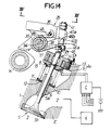
- Valve driving means 35 is interposed between the intake valve 5 and the intake cam 15 and comprises a rocker arm 36 pivotally carried on the rocker shaft 17 for swinging movement in sliding contact with the intake cam 15, a sliding plunger 37 carried on the rocker arm 36 for sliding movement in abutment against the upper end of the valve stem 5a of the intake valve 5, and torsion springs 38 as valve-opening resilient members interposed between the rocker arm 36 and the sliding plunger 37.
- the rocker arm 36 is carried on the rocker shaft 17 through a collar 39.
- a basically cylindrical stopper 40 is fitted over the sliding plunger 37 so that the axial position thereof relative to the sliding plunger 37 may be variable such as by a threaded connection.
- the stopper 40 is slidably fitted in the rocker arm 36 to define a lowermost limit position of the sliding plunger 37 relative to the rocker arm 36.
- a lock nut 41 is also fitted over the sliding plunger 37 for locking the position of the stopper 40.
- the rocker arm 36 is provided with a hole comprising a larger diameter hole portion 42 and a smaller diameter hole portion 43 which are coaxially connected in sequence from the above, and the stopper 40 is provided with a larger diameter portion 40a slidably fitted in the larger diameter hole portion 42 and a smaller diameter portion 40b slidably fitted in the smaller diameter hole portion 43.
- the lowermost limit position of the stopper 40 i.e., of the sliding plunger 37 relative to the rocker arm 36 is defined by abutment of a stepped portion between the larger diameter portion 40a and the smaller diameter portion 40b against a stepped portion between the larger diameter hole portion 42 and the smaller diameter hole portion 43.
- a damper mechanism D5 is provided between the rocker arm 36 and the stopper 40 fixedly mounted on the sliding plunger 37 and includes a hydraulic chamber 44 defined between the rocker arm 36 and the stopper 40.
- the hydraulic chamber 44 communicates with a hydraulic pressure supply passage 85 within the rocker shaft 17 through a passage 49 made in the rocker arm 36.
- the damper mechanism D5 performs a buffering effect during downward sliding movement of the sliding plunger 37 by permitting a hydraulic pressure to leak through the clearance between the stopper 40 and the rocker arm 36.
- a damper mechanism D1 is also provided between the valve stem 5a of the intake valve 5 and the electromagnet 13.
- An arm member 46 is fixedly mounted on a lower portion of the sliding plunger 37 through a cotter 45.
- the arm member 46 is comprised of a disk portion 46a and pin-like locking portions 46b provided on the disk portion 46a to project therefrom along one diametrical line of the disk portion 46a.
- the arm member 46 is fixed on the sliding plunger 37 by press-fitting the cotter 45 into a wedge which is centrally made in the disk portion 46a to gradually decrease in diameter upwardly.
- the torsion springs 38 are engaged at one ends thereof with a locking pin 48 fixed on the rocker arm 36 to project oppositely sideways in parallel to the rocker shaft 17, and at the other ends thereof with locking portions 46b of the arm member 46, respectively.
- the torsion springs 38 exhibit repulsive forces in a direction to allow the rocker arm 36 to slide on the the intake cam 15 and in a direction to bring the sliding plunger 37 into abutment against the intake valve 5.
- a lock mechanism R3 is provided between the rocker arm 36 and the sliding plunger 37.
- the lock mechanism R3 comprises an annular locking groove 86 as locking means provided in an outer surface of the larger diameter portion 40a of the stopper 40 substantially integral with the sliding plunger 37, and a locking member 87 disposed in the rocker arm 36 for advancing and retreating movements and having at its leading end a substantially U-shaped engage claw 87a capable of engaging the locking groove 86.
- the rocker arm 36 is provided with a slide hole 88 having an axis perpendicular to an axis of the sliding plunger 37, with an end of the slide hole 88 opposite from the sliding plunger 37 being closed by a cap 89.
- An operating piston 91 is slidably received in the slide hole 88 and defines a hydraulic chamber 90 between the cap 89, and a base end of the locking member 87, which is inserted in the slide hole 88 with the engage claw 87a at its leading end being projectable from an opened end of the slide hole 88 closer to the sliding plunger 37, is secured to the operating piston 91.
- a return spring 92 is interposed between the operating piston 91 and the rocker arm 36 to surround the locking member 87 within the slide hole 88 for biasing the operating piston 91 and thus the locking member 87 in a direction to reduce the volume of the hydraulic chamber 90.
- the rocker arm 36 is also provided with a passage 93 communicating with the hydraulic chamber 90.
- the passage 93 is normally in communication with a hydraulic pressure supply passage 94 made in the rocker shaft 17 independently of the above-described hydraulic pressure supply passage 85.
- the hydraulic pressure supply passage 94 is connected to a hydraulic pressure supply source which is not shown, so that the operating piston 91 may be operated in a direction to allow the engage claw 87a at the leading end of the locking member 87 to project from the slide hole 88, by supplying hydraulic pressure from the hydraulic supply source into the hydraulic chamber 90.
- annular groove 95 is provided in an outer surface at a middle portion of the operating piston 91, and an engage sphere 96 is disposed to face an intermediate portion of the slide hole 88 and is engagible in the annular groove 95 in a condition where the piston 91 has been moved to a position to permit the engage claw 87a at the leading end of the locking member 87 to project from the slide hole 88.
- the engage sphere 96 is carried in the rocker arm 36 for movement in a radial direction of the operating piston 91 between a position in which it engages the annular groove 95 and a position in which such engagement has been released.
- a hydraulic pressure in the passage 93 acts on a back of the engage sphere 96.
- the locking groove 86 provided in the stopper 40 substantially integral with the sliding plunger 37 is disposed at a location where the engage claw 87a of the locking member 87 can be engaged in the locking groove when the sliding plunger 37 has been moved relative to the rocker arm 36 to the uppermost limit position.
- the electro-magnetic actuator A1 is comprised of the electromagnet 13 and the spring retainer 9.
- the energization of the electromagnet 13 of the electromagnetic actuator A1 makes it possible to retain the intake valve 5 in its closed position by upward movement of the sliding plunger 37 relative to the rocker arm 36, even with the rocker arm 36 in slide contact with a lobe portion of the intake cam 15 as shown in Fig.18
- the valve-opening force accumulated by the torsion springs 38 can be allowed to suddenly act on the intake valve 5 as shown in Fig.19, thereby opening the intake valve 5 quickly, wherein the rate of valve opening can be moderated by the damper mechanisms D1 and D5.
- the supplying of a hydraulic pressure into the hydraulic chamber 90 in the lock mechanism R3 allows the engage claw 87a at the leading end of the locking member 87 to be engaged into the locking groove 86, and by maintaining such state by engagement of the engage sphere 96 in the annular groove 95, the rocker arm 36 can be substantially united with the sliding plunger 37, so that the intake valve 5 can be operated to be opened and closed in positive correspondence to the profile of the intake cam 15.
- the length of rocker arm 36 supported on the rocker shaft 17 can be relatively lengthened in order to ensure a surface pressure on the rocker shaft 17. Further, the structure can be simplified, leading to a convenience in workability such as boring as well as assuring of accuracy.
- Fig.20 illustrates a seventh embodiment of the present invention, wherein a lock mechanism R4 is provided between the rocker arm 36 and the sliding plunger 37.
- the lock mechanism R4 comprises a locking member 97 carried on the rocker arm 36 for swinging movement between a position (illustrated by a chain line in Fig.20) in which it is engaged with a lock nut 41' threadedly attached on an upper end of the sliding plunger 37 to maintain the position of the stopper 40 and a position (illustrated by a solid line in Fig.20) in which such engagement has been released, an operating piston 98 disposed in the rocker arm 36 for advancing and retreating movements to urge the locking member 97 toward the engaged position, and a hydraulic chamber 99 provided in the rocker arm 36 to face a back of the operating piston 98 in order to allow a hydraulic pressure to act on the operating piston 98.
- the locking member 97 is formed to have a substantially U-shaped cross-section so as to engage the lock nut 41' from the above and carried at its base end on the rocker arm 36 by a stub shaft 100 having an axis extending in a direction perpendicular to an axis of the sliding plunger 37.
- the rocker arm 36 is provided with a slide hole 101 having an axis perpendicular to an axis of the sliding plunger 37, with an end of the slide hole 101 opposite from the sliding plunger 37 being closed by a cap 102.
- An operating piston 98 is slidably received in the slide hole 101 and defines the hydraulic chamber 99 between the cap 102, with a leading end of the piston abutting against a back of a base end of the locking member 97.
- a return spring 103 is interposed between an inner surface of the base end of the locking member 97 and the rocker arm 36 for biasing the operating piston 98 in a direction of swinging movement of the locking member 97 toward the disengaged position, i.e., in a direction to reduce the volume of the hydraulic chamber 99.
- the hydraulic chamber 99 is normally in communication with a hydraulic pressure supply passage 94 in the rocker shaft 17 through a passage 93 in the rocker arm 36.
- an engage sphere 105 is disposed in an intermediate portion of the slide hole 101 and adapted to engage an annular groove 104 provided in an outer surface of an intermediate portion of the operating piston 98 when the locking member 97 has been swung to the engaged position.
- the intake valve 5 can be operated to be opened and closed along the profile of the intake cam 15 with the relative operation of the rocker arm 36 and the sliding plunger 37 being blocked by the lock mechanism R4.
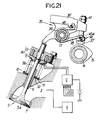
- Fig.21 illustrates an eighth embodiment of the present invention, wherein portions corresponding to those in each of the previous embodiments are designated by the same reference characters.
- the eighth embodiment is similar to the sixth embodiment, but it should be noted that a rocker arm 36' abuts against the valve stem 5a of the intake valve 5, and a sliding plunger 37' in slidable contact with the intake cam 15 is slidably carried on the rocker arm 36'.
- the timing of opening the intake valve 5 can be freely controlled to improve the intake or suction efficiency.
- Figs.22 to 26 illustrate a ninth embodiment of the present invention, wherein portions corresponding to those in each of the previous embodiments are designated by the same reference characters.
- a cylindrical support 106 is integrally formed on the cylinder head 1 to extend upwardly in an axial direction of the intake valve 5, and a valve-operating cam shaft 14 is rotatably supported by a bearing half 107 formed on the cylindrical support and a bearing cap 108 secured to an upper surface of the bearing half 107.
- An intake cam 15 provided on the valve-operating cam shaft 14 is linked to the intake valve 5 through a valve lifter 110 as valve driving means.
- a hollow cylinder portion 109 is formed in the cylindrical support 106 of the cylinder head 1 and connects the intake cam 15 with the intake valve 5, and the valve lifter 110 is contained in the hollow cylinder portion 109.
- the valve lifter 110 is comprised of a lower lifter portion 111 slidably received in a bottomed hollow cylinder formed in the hollow cylinder portion 109, a hat-like upper lifter portion 112 vertically slidably fitted in the lower lifter portion 111 from its upper opened portion, two lifter springs 113 and 114 as valve-opening resilient members provided in compression between the lower lifter portion 111 and the upper lifter portion 112 for biasing the lower and upper lifter portions to expand from each other, and a set nut 115 threadedly attached to the upper opened portion of the lower lifter portion 111 and adapted to engage the upper lifter portion 112 to define an upper limit position of the upper lifter portion 112.
- a projecting pin 116 is integrally provided on the lower lifter portion 111 to project from a central portion of a lower surface of the lower lifter portion 111, with a lower end of the projecting pin 116 permitted to abut against an upper end of the valve stem 5a of the intake valve 5.
- a cam surface of the intake cam 15 is also permitted to abut against an upper surface of the upper lifter portion 112.
- the repulsive forces of the lifter springs 113 and 114 are set to be larger than those of the valve springs 11 and 12.
- An electromagnet 13 is fixedly mounted on a lower portion of the cylindrical support 106 and constitutes an electromagnetic actuator A1 in cooperation with an upper surface of the spring retainer 9. Inserted into a hollow portion of the electromagnet 13 is an abutment portion of the upper end of the valve stem 5a of the intake valve 5 in abutment with the projecting pin 116 integral with the lower lifter portion 111.
- a damper mechanism D6 is provided between the lower lifter portion 111 and the cylindrical support 106.
- the damper mechanism D6 comprises an annular hydraulic chamber 117 provided between an outer peripheral surface of the lower lifter portion 111 and an inner peripheral wall of the cylindrical support 106.
- An oil supply port 118 and an oil discharge port 119 are made in the cylindrical support 106 to communicate with the hydraulic chamber 117, and a hydraulic circuit, for example, a lubricating-oil circuit for the engine is connected to the hydraulic chamber 117, so that a pressure oil may be circulated through the chamber 117.
- the pressure oil flowing into the hydraulic chamber 117 provides a buffering effect and a lubricating effect on the valve lifter 110 when it acts on a downwardly faced pressure receiving surface 120 formed on the outer peripheral surface of the lower lifter portion 111 to lift the valve lifter 110.
- a lock mechanism R5 is interposed between the lower lifter portion 111 and the upper lifter portion 112 slidably fitted in the lower lifter portion 111.
- the lock mechanism R5 comprises a locking member 122 slidably received in a bottomed slide hole 121 centrally provided in the lower lifter portion 111, a hydraulic chamber 123 defined between the locking member 122 and a closed end of the slide hole 121, an abutting pin 124 provided at a central portion of the upper lifter portion 112 to be able to abut against an upper end of the locking member 122, and a return spring 125 interposed between the locking member 122 and the upper lifter portion 112 to exhibit a spring force in a direction to reduce the volume of the hydraulic chamber 123.
- the locking member 122 is provided with an oil passage 126 communicating with the hydraulic chamber 123, and the lower lifter portion 111 is provided with an oil passage 127 which normally communicates with the oil passage 126 irrespective of the relatively moved position of the lower lifter portion 111 relative to the locking member 122.
- the cylindrical support 106 is provided with an oil passage 128 which normally communicates with the oil passage 127 irrespective of the upper and lower positions of the lower lifter portion 111 and which is connected through a connecting hole 129 to a hydraulic pressure supply source which is not shown.
- the axial length of the abutting pin 124 is set such that it will not abut against the upper end of the locking member 122 in a condition of no hydraulic pressure supplied into the hydraulic chamber 123, even if the lower and upper lifter portions 111 and 112 are relatively moved at a maximum toward each other.
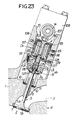
- the intake valve 5 can be retained in its closed state, as shown in Fig.23, irrespective of the turned position of the intake cam 15. Then, if maintaining of the closed position by the electromagnetic actuator A1 is released, the accumulated spring forces of the lifter springs 113 and 114 cause the intake valve 5 to be opened as shown in Fig.24.
- the hydraulic pressure is confined in the hydraulic chamber 117 in the damper mechanism D6 and leaks through a clearance between the lower lifter portion 111 and the cylindrical support 106. Accordingly, in a region where the energy released from the lifter springs 113 and 114 is larger, the opening of the intake valve 5 is moderated by a buffering effect of the damper mechanism D6.
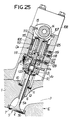
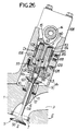
- the locking member 122 is moved up to abut against the abutment pin 124 as shown in Fig.25, thereby inhibiting the downward movement of the upper lifter portion 112 relative to the lower lifter portion 111. Therefore, if the upper lifter portion 112 is urged downwardly by the intake cam 15 as shown in Fig.26, the lower lifter portion 111 is also driven downwardly in a one piece, so that the intake valve 5 can be driven to be opened and closed in correspondence to the profile of the intake cam 15.
- Fig.27 illustrates a tenth embodiment of the present invention, wherein like reference numerals are used to designate portions corresponding to those in the ninth embodiment.
- a valve lifter 110' as valve driving means comprises a lower lifter portion 111' slidably received in the hollow cylinder portion 109 in the cylindrical support 106, a upper lifter portion 112' slidably received in the hollow cylinder portion 109, and a pair of lifter springs 113 and 114 interposed between the lower and upper lifter portions 111' and 112'.
- a lock mechanism R6 is interposed between the lower and upper lifter portions 111' and 112'.
- a projecting pin 116' abutting against the upper end of the intake valve 5 is threadedly connected at its upper end to a central portion of the lower lifter portion 111'.
- An upwardly extending cylindrical portion 130 is also coaxially mounted on a central upper portion of the lower lifter portion 111', and a pin 131 provided to project on a central lower portion of the upper lifter portion 112' which is in slide contact with the intake cam 15 is slidably received in the cylindrical portion 130.
- a threaded member 134 is threadedly attached to a leading end of the pin 131 and adapted to engage a locking step or shoulder 132 provided on an upper end of the cylindrical portion 130.
- the lock mechanism R6 comprises a hydraulic chamber 133 defined within the cylindrical portion 139 between the upper end of the projecting pin 116' and a lower end of the pin 131, so that supplying of a hydraulic pressure into the hydraulic chamber 133 inhibits the downward movement of the pin 131 and thus the upper lifter portion 112' relative to the lower lifter portion 111'.
- An oil passage 135 is provided in the projecting pin 116' to communicating with the hydraulic chamber 133 and is normally in communication with the an oil passage 128 made in the cylindrical support 106.
- Figs.28, 29 and 30 illustrate an eleventh embodiment of the present invention, wherein like reference numerals designate portions corresponding to those in the previous ninth embodiment.
- a damper mechanism D7 is provided in addition to the damper mechanism D6 of the ninth embodiment. Specifically, the damper mechanism D6 is disposed between the lower lifter portion 111 and the cylindrical support 106, while the damper mechanism D7 is disposed between the lower lifter portion 111 and the upper lifter portion 112.
- the damper mechanism D7 comprises a hydraulic chamber 136 provided between a set nut 115 integral with the lower lifter portion 111 and the upper lifter portion 112.
- the hydraulic chamber is communicatable with an oil supply port 118 through a communication passage 137 made in the lower lifter portion 111.
- the communication passage 137 is made in the lower lifter portion 111 to communicate with the oil supply passage 118 when the upper lifter portion 112 is in a position in which it has been forced down at a maximum while maintaining the intake valve 5 closed, and to block such communication with the oil supply passage 118 when the lower lifter portion 111 is forced downwardly with the upper lifter portion 112 in its lowermost position.
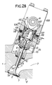
- the intake valve 5 can be held at its closed state irrespective of the turned positions of the intake cam 15, as shown in Fig.28, and during this time, each of the hydraulic chambers 117 and 136 in both damper mechanisms D6 and D7 is filled up with a hydraulic pressure.
- the intake valve 5 is opened by accumulated spring forces of the lifter springs 113 and 114, as shown in progress in Fig. 29.
- a hydraulic pressure is confined in the hydraulic chamber 136 in the damper mechanism D7.
- Such hydraulic pressure leaks through clearances between the set nut 115 and the upper lifter portion 112 and between the lower and upper lifter portions 111 and 112, the lower lifter portion 111 is forced down and hence, the opening of the intake valve 5 is moderated.
- Such buffering effect of the damper mechanism D7 is effective over the entire region of lift of the intake valve 5.
- Figs.31 to 34 illustrate a twelfth embodiment of the present invention, wherein like reference numerals are used to designate portions corresponding to those of the individual previous embodiments.
- an electromagnetic actuator A1 as valve-closed position retainer means for maintaining the intake valve 5 in its closed position
- an electromagnetic actuator A2 as valve-opened position retainer means for maintaining the intake valve 5 in the open position.
- an annular electromagnet 140 is secured to the cylinder head 1 in an opposed relation to the lower surface of the spring retainer 9 to surround the valve stem 5a of the intake valve 5 and constitutes an electromagnetic actuator A2 in cooperation with the magnetic element 9 which also serves as the spring retainer.
- the magnetic element 9 is attracted to the electromagnet 140 by excitation of a solenoid of the electromagnet 140, and the attracting force of the electromagnetic actuator A2 is set to be larger than the spring force of the valve spring 11. Accordingly, when the electromagnet 140 is excited in opening the intake valve 5, the opened position of the intake valve 5 is maintained regardless of rotation of the valve-operating cam shaft 14.
- the electromagnet 13 is energized under a control by the control circuit C to attract the magnetic element 9 to the electromagnet 13, while the circular base portion of the intake cam 15 is sliding on the first rocker arm 18 as shown in Fig.31, i.e., before the intake valve 5 becomes lifted.
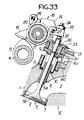
- the first rocker arm 18 is only swung while twisting the torsion springs 20, as shown in Fig.33.
- the intake valve 5 is maintained at the closed position, and the opening force provided by the intake cam 15 is accumulated by the torsion springs 20.
- the electromagnet 140 When the amount of lift of the intake valve 5 has become maximum, the electromagnet 140 is energized under a control by the control circuit C to attract the magnetic element 9 to the electromagnet 140. This operates the electromagnetic actuator A2, so that the intake valve 5 is maintained at its opened position and remains opened irrespective of turned positions of the intake cam 15. When the excitation of the electromagnet 140 is then released, the intake valve 5 is operated to be closed by the spring force of the valve spring 11 independently of the cam profile. After the valve stem 5a has abutted against the tappet screw 24 of the valve driving means 16, the intake valve 5 is closed in a usual curve of lift by the coaction of the intake cam 15 and the valve spring 11.
- timings of opening and closing the intake valve 5 can be set at any points by the control of change-over of the retained state and the retaining-released state provided by the electromagnetic actuators A1 and A2, and an appropriate valve-operating control can be carried out depending upon the operational condition of the engine.
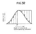
- the retaining by the electromagnetic actuators A1 and A2 can be conducted at any timing, as shown in a thin solid line in Fig.32, regardless of the operational condition of the engine. That is, the electromagnetic actuators A1 and A2 make it possible to change the valve-opening and closing timings at any point between from a point just before the start of cam lifting to a point of the maximum amount of lift, as well as between from the point of the maximum amount of lift to a point just before the completion of cam lifting.
- the energization of both electromagnetic actuators A1 and A2 is normally interrupted, opening and closing timings substantially along the cam profile may be obtained.
- the construction is such that the relative swinging movements of the rocker arms 18 and 19 are blocked, opening and closing timings surely along the cam profile may be obtained.
- Fig.35 illustrates a thirteenth embodiment of the present invention, wherein like reference numerals designate portions corresponding to those in the individual previous embodiments.
- Valve driving means 35 is interposed between the intake valve 5 and the intake cam 15.
- An electromagnetic actuator A1 is comprised of the upper surface of the spring retainer 9 and the electromagnet 13
- an electromagnetic actuator A2 is comprised of the lower surface of the spring retainer 9 and the electromagnet 140.
- the attracting force of the first actuator A1 and the spring force of the valve spring 11 are set to larger than the repulsive forces of the torsion springs 38, while the attracting force of the electro-magnetic actuator A2 is set to be larger than the spring force of the valve spring 11.
- electromagnetic actuator A1 With the thirteenth embodiment, energization of the electromagnet 13 of the electromagnetic actuator A1 enables the intake valve 5 to be retained at its closed state, and controlling of the timing of releasing such retained state enables the timing of opening the intake valve 5 to be controlled.
- electromagnetic actuator A2 makes it possible to maintain the opened state of the intake valve 5, and controlling of the timing of releasing such opened state enables the timing of closing the intake valve 5 to be controlled. Accordingly, it is possible to provide an effect similar to that of the previous twelfth embodiment.
- Fig.36 illustrates a fourteenth embodiment of the present invention, wherein like reference numerals denote portions corresponding to those in the individual previous embodiments.
- the electromagnet 13 is fixed mounted on the lower portion of the cylindrical support 106 containing the valve lifter 110 and constitutes an electromagnetic actuator A1 by cooperation with the upper surface of the spring retainer 9, and the electromagnet 140 is also fixedly mounted on the cylinder head 1 and constitutes the electro-magnetic actuator A2 by cooperation with the lower surface of the spring retainer 9.
- the electro-magnetic actuator A1 makes it possible to maintain the closed position of the intake valve 5 to retain the intake valve 5 in its closed state, while the electromagnetic actuator A2 makes it possible to maintain the opened state of the intake valve 5, thus providing an effect similar to those in the above-described twelfth and thirteenth embodiments.
- a valve operation control system in an internal combustion engine which is of simplified constructions and is a further improvement to the above-described system of Japanese Patent Application No. 123647/87 which moderates the opening of the engine valve upon releasing of the retaining by the closed-position retaining means, thereby preventing the engine valve from being damaged; which opens and closes the engine valve in accordance with a profile of the valve-operating cam when the closed-position retaining means is inoperative; and which enables not only the timing of opening the engine valve but also the timing of closing it to be controlled, thereby providing a further improvement in intake or exhaust efficiency.
Landscapes
- Engineering & Computer Science (AREA)
- Mechanical Engineering (AREA)
- General Engineering & Computer Science (AREA)
- Valve Device For Special Equipments (AREA)
Claims (25)
- Système de commande du fonctionnement d'une soupape d'un moteur à combustion interne, comprenant une soupape (5) de moteur, supportée dans un corps (E) de moteur de manière à pouvoir être ouverte et fermée, des moyens (11, 12) de ressort de soupape destinés à rappeler ladite soupape (5) de moteur dans le sens d'une fermeture de la soupape, et des moyens (16; 35; 110; 110') d'actionnement de la soupape intercalés entre une came (15) de commande de la soupape et la soupape (5) de moteur de manière à transmettre une force dirigée dans le sens d'une ouverture de la soupape, de la came (15) de commande de la soupape à la soupape (5) de moteur, système dans lequel ledit moyen (16; 35; 110; 110') d'actionnement de la soupape est pourvu d'un élément élastique (20; 38; 113; 114) d'ouverture de la soupape, destiné à exercer une force répulsive dans le sens d'une ouverture de ladite soupape de moteur, et dans lequel ledit système comprend des moyens (A1) de maintien en position fermée intercalés entre ladite soupape (5) de moteur et ladite came (15) de commande de la soupape, destinés à maintenir la soupape (5) de moteur dans sa position fermée, toute force d'ouverture de la soupape fournie par la came (15) de commande de la soupape étant alors accumulée dans l'élément élastique (20; 38; 113; 114) d'ouverture de la soupape, lesdits moyens (A1) de maintien en position fermée étant agencés de manière à pouvoir être commutés entre un état de retenue et un état de relâchement de manière à commander le calage de l'ouverture de ladite soupape (5) de moteur en fonction des conditions de fonctionnement du moteur,
caractérisé en ce que la force répulsive fournie par l'élément (20; 38; 113; 114) est prévue pour être supérieure à la force de rappel des moyens (11, 12) de ressort de soupape, et pour s'opposer à ladite force de rappel de manière à provoquer l'ouverture de ladite soupape (5) de moteur. - Système de commande du fonctionnement d'une soupape d'un moteur à combustion interne selon la revendication 1, dans lequel ledit moyen de maintien en position fermée comprend un actionneur électromagnétique (A1).
- Système de commande du fonctionnement d'une soupape d'un moteur à combustion interne selon l'une des revendications 1 ou 2, dans lequel ledit moyen (16) d'actionnement de la soupape comporte en outre un premier culbuteur (18) plus proche de la came de commande de la soupape, et un deuxième culbuteur (19) plus proche de la soupape (5) de moteur, pouvant osciller autour d'un axe commun avec le premier culbuteur (18), et dans lequel ledit élément élastique (20) est intercalé entre les culbuteurs (18, 19).
- Système de commande du fonctionnement d'une soupape d'un moteur à combustion interne selon l'une des revendications 1 ou 2, dans lequel ledit moyen (35) d'actionnement de la soupape comprend un culbuteur (36; 36'), un poussoir coulissant (37; 37') porté de façon coulissante par le culbuteur (36; 36') de manière à effectuer un mouvement coulissant en étant en butée soit contre la came (15) de commande de la soupape, soit contre la soupape (5) de moteur, ledit élément élastique (38) d'ouverture de la soupape étant intercalé entre le culbuteur (36; 36') et le poussoir coulissant (37; 37').
- Système de commande du fonctionnement d'une soupape d'un moteur à combustion interne selon la revendication 4, comprenant en outre un élément de bras (46) monté de façon fixe sur le poussoir coulissant (37; 37') par l'intermédiaire d'une clavette (45), ledit élément de bras (46) comportant une partie (46b) de blocage de l'élément élastique (38) d'ouverture de la soupape.
- Système de commande du fonctionnement d'une soupape d'un moteur à combustion interne selon l'une des revendications 1 ou 2, dans lequel ledit moyen (110; 110' ) d'actionnement de la soupape comprend une partie supérieure (112; 112') de poussoir, plus proche de la came (15) de commande de la soupape, une partie inférieure (111; 111') de poussoir, plus proche de la soupape (5) de moteur, lesdites parties supérieure et inférieure (111, 112; 111', 112') de poussoir étant ajustées l'une par rapport à l'autre, et ledit élément élastique (113, 114) étant intercalé entre lesdites parties supérieure et inférieure (111, 112; 111', 112') de poussoir de manière à exercer une force élastique dans une direction de manière à éloigner lesdites parties supérieure et inférieure (111, 112; 111', 112') de poussoir l'une de l'autre.
- Système de commande du fonctionnement d'une soupape d'un moteur à combustion interne selon l'une quelconque des revendications précédentes, dans lequel ledit moyen (16; 35; 110; 110') d'actionnement de la soupape comporte un mécanisme amortisseur (D₂, D₃, D₄, D₅, D₇) destiné à amortir l'action d'ouverture de la soupape par le moyen d'actionnement de la soupape, qui est générée par une force répulsive de l'élément élastique (20; 38; 113, 114) d'ouverture de la soupape.
- Système de commande du fonctionnement d'une soupape d'un moteur à combustion interne selon la revendication 7, dans lequel ledit moyen (16; 35; 110; 110') d'actionnement de la soupape comporte des premier et second moyens (18, 19; 36, 37; 36', 37'; 111, 112; 111', 112') pouvant être déplacés l'un par rapport à l'autre, et dans lequel ledit élément élastique (20; 38; 113, 114) d'ouverture de la soupape est intercalé entre les deux éléments d'actionnement, et ledit mécanisme amortisseur (D₂, D₃, D₄, D₅, D₇) est disposé au niveau d'une partie de contact à choc située entre les deux éléments d'actionnement.
- Système de commande du fonctionnement d'une soupape d'un moteur à combustion interne selon la revendication 8, dans lequel ledit mécanisme amortisseur (D₂; D₃) est disposé entre un premier culbuteur (18) plus proche de la came de commande, servant de premier élément d'actionnement, et un deuxième culbuteur (19) servant de second élément d'actionnement, oscillant autour d'un axe commun avec ledit premier culbuteur (18), ledit mécanisme amortisseur (D₂; D₃) comprenant un piston (58; 69) reçu de façon coulissante dans l'un des dits premier et deuxième culbuteurs (18, 19), et une chambre hydraulique (59; 70) définie de manière à faire face au dos du piston (58; 69) afin d'exercer une pression hydraulique destinée à forcer ledit piston (58; 69) en butée contre l'autre dit premier ou second culbuteur (18, 19).
- Système de commande du fonctionnement d'une soupape d'un moteur à combustion interne selon la revendication 8, dans lequel ledit mécanisme amortisseur (D₄) est disposé entre un premier culbuteur (18) plus proche de la came (15) de commande de la soupape, servant de premier élément d'actionnement, et un second culbuteur (19) servant de second élément d'actionnement, oscillant autour d'un axe commun avec ledit premier culbuteur, ledit mécanisme (D₄) comprenant un alésage de coulissement (78) réalisé dans l'un des dits premier et second culbuteurs (18, 19), une sphère (76) reçue de façon coulissante dans ledit alésage de coulissement (78), et une chambre hydraulique (77) définie de manière à faire face au dos de la sphère (76) afin d'amener ladite sphère en butée contre l'autre dit premier ou second culbuteur (18, 19); et comprenant en outre un jeu (80) défini entre une surface externe de ladite sphère (76) et une surface interne du dit alésage de coulissement (78) et adapté pour permettre une fuite de pression hydraulique à l'intérieur de la chambre hydraulique (70) pendant le mouvement de ladite sphère (76) vers l'intérieur du dit alésage de coulissement.
- Système de commande du fonctionnement d'une soupape d'un moteur à combustion interne selon la revendication 8, dans lequel ledit mécanisme amortisseur (D₅) est disposé entre un culbuteur (36; 36') plus proche de la came de commande de la soupape, servant de premier élément d'actionnement, et un poussoir coulissant (37; 37') porté de façon coulissante sur ledit culbuteur en venant buter contre la soupape de moteur, et servant de second élément d'actionnement, ledit mécanisme amortisseur comportant une chambre hydraulique (44) à travers laquelle le volume de fuite de pression peut être limité.
- Système de commande du fonctionnement d'une soupape d'un moteur à combustion interne selon la revendication 8, dans lequel ledit mécanisme amortisseur (D₇) est disposé entre une partie inférieure (111; 111') de poussoir plus proche de la soupape de moteur, servant de premier élément d'actionnement, et une partie supérieure (112; 112') de poussoir, ajustée de façon coulissante dans ladite partie inférieure de poussoir plus proche de la came de commande de la soupape, servant de second élément d'actionnement, ledit mécanisme amortisseur comprenant une chambre hydraulique (136) à travers laquelle le volume de fuite de pression peut être limité.
- Système de commande du fonctionnement d'une soupape d'un moteur à combustion interne selon l'une quelconque des revendications précédentes, dans lequel ledit mécanisme amortisseur (D₁; D₆) est disposé entre la soupape (5) de moteur ou un élément de blocage relié de façon fonctionnelle à ladite soupape (5), et un élément de guidage stationnaire (13) destiné à guider le fonctionnement de ladite soupape de moteur ou l'élément de blocage, ledit mécanisme amortisseur (D₁; D₆) étant adapté pour modérer l'ouverture de la soupape de moteur, ouverture qui est causée par la force répulsive de l'élément élastique d'ouverture de la soupape.
- Système de commande du fonctionnement d'une soupape d'un moteur à combustion interne selon la revendication 13, dans lequel ledit mécanisme amortisseur (D₁) comporte une chambre hydraulique (34) à travers laquelle le volume de fuite de pression peut être limité, et qui est définie entre une partie étagée ou épaulement formé(e) dans la partie supérieure de la soupape de moteur et ledit élément de guidage.
- Système de commande du fonctionnement d'une soupape d'un moteur à combustion interne selon la revendication 13, dans lequel ledit moyen d'actionnement de la soupape comporte une partie inférieure (111; 111') de poussoir, plus proche de la soupape de moteur, une partie supérieure (112; 112') de poussoir ajustée de façon coulissante dans ladite partie inférieure de poussoir, et un élément élastique (113, 114) d'ouverture de la soupape intercalé entre lesdites parties inférieure et supérieure de poussoir, et dans lequel ledit mécanisme amortisseur (D₆) comporte une chambre hydraulique (133) a travers laquelle le volume de fuite de pression peut être limité, et qui est définie entre la partie inférieure (111; 111') de poussoir servant d'élément de blocage et un support cylindrique (106) servant d'élément de guidage monté de façon fixe sur une culasse, de manière à guider le mouvement de ladite partie inférieure (111; 111') de poussoir.
- Système de commande du fonctionnement d'une soupape d'un moteur à combustion interne seton l'une quelconque des revendications précédentes, dans lequel ledit moyen d'actionnement (16; 35; 110; 110') est pourvu d'un mécanisme (R₁; R₂; R₃; R₄; R₅; R₆) de blocage adapté pour bloquer la fonction élastique de l'élément élastique d'ouverture de la soupape.
- Système de commande du fonctionnement d'une soupape d'un moteur à combustion interne selon la revendication 16, dans lequel ledit moyen (16; 35; 110; 110') d'actionnement de la soupape comporte des premier et second éléments (18, 19; 36, 37; 36', 37'; 111, 112; 111', 112') d'actionnement pouvant être déplacés l'un par rapport à l'autre, ledit élément élastique (20; 38; 113; 114) d'ouverture de la soupape étant intercalé entre lesdits éléments d'actionnement, et dans lequel ledit mécanisme de blocage (R₁; R₂; R₃; R₄; R₅; R₇) est disposé entre deux des dits éléments d'actionnement et comporte une chambre hydraulique (52; 90; 99; 123; 133) adaptée pour fournir une pression hydraulique dans le sens d'un blocage du déplacement relatif des éléments d'actionnement contre la force répulsive de l'élément élastique d'ouverture de la soupape.
- Système de commande du fonctionnement d'une soupape d'un moteur à combustion interne selon la revendication 17, dans lequel mécanisme de blocage (R₁, R₂) est intercalé entre un premier culbuteur (18) plus proche de la came de commande de la soupape, servant de premier élément d'actionnement, et un second culbuteur (19) servant de second élément d'actionnement, pouvant osciller autour d'un axe commun avec ledit premier culbuteur.
- Système de commande du fonctionnement d'une soupape d'un moteur à combustion interne selon la revendication 17, dans lequel ledit mécanisme de blocage (R₅; R₇) est intercalé entre une partie inférieure (111) de poussoir plus proche de la soupape de moteur, servant de premier élément d'actionnement, et une partie supérieure (112) de poussoir, pouvant se déplacer par rapport à ladite première partie de poussoir, disposée à proximité de la came de commande de la soupape et servant de second élément d'actionnement.
- Système de commande du fonctionnement d'une soupape d'un moteur à combustion interne selon la revendication 17, dans lequel ledit mécanisme de blocage (R₁; R₂; R₃; R₄) comporte un élément de blocage pouvant être mis en engagement avec l'un des dits premier et second éléments d'actionnement et disposé dans l'autre élément d'actionnement, en vue d'un mouvement entre une position engagée et une position désengagée.
- Système de commande du fonctionnement d'une soupape d'un moteur à combustion interne selon la revendication 20, dans lequel ledit mécanisme de blocage (R₁; R₂) comporte une partie (84) de blocage disposée sur l'un des dits premier culbuteur (18) plus proche de la came de commande de la soupape, servant de premier élément d'actionnement, et second culbuteur (19) pouvant osciller autour d'un axe commun avec ledit premier culbuteur (18), ledit élément de blocage (51) étant disposé sur l'autre dit premier ou second culbuteur (18, 19), en vue d'effectuer des mouvements d'avance et de recul entre une position dans laquelle il est en engagement avec ladite partie (84) de blocage et une position de relâchement d'un tel engagement.
- Système de commande du fonctionnement d'une soupape d'un moteur à combustion interne selon la revendication 20, dans lequel ledit moyen d'actionnement de la soupape comporte un culbuteur (36) en contact de glissement avec la came de commande de la soupape et servant de premier élément d'actionnement, un poussoir coulissant (37) servant de second élément d'actionnement et porté de façon coulissante sur le culbuteur de manière à être en butée sur la soupape de moteur, ledit élément élastique (38) d'ouverture de la soupape étant intercalé entre ledit culbuteur et ledit poussoir coulissant, et dans lequel un mécanisme (R₃) de blocage comporte une partie (86) de blocage disposée dans ledit poussoir coulissant (37), et dans lequel ledit élément (87) de blocage est disposé sur le culbuteur (36) en vue d'effectuer des mouvements d'avance et de recul entre une position dans laquelle il est en engagement avec ladite partie de blocage et une position de relâchement d'un tel engagement.
- Système de commande du fonctionnement d'une soupape d'un moteur à combustion interne selon la revendication 20, dans lequel ledit moyen d'actionnement de la soupape comporte un culbuteur (36) en contact de glissement avec la came de commande de la soupape et servant de premier élément d'actionnement, un poussoir coulissant (37) servant de second élément d'actionnement et porté de façon coulissante sur le culbuteur de manière à être en butée sur la soupape de moteur, ledit élément élastique (38) d'ouverture de la soupape étant intercalé entre ledit culbuteur (34) et ledit poussoir coulissant (37), et dans lequel un mécanisme (R₄) de blocage comporte un élément (97) de blocage porté sur ledit culbuteur de manière à effectuer des mouvements oscillants entre une position dans laquelle il est en engagement avec ledit poussoir coulissant (37) et une position de relâchement d'un tel engagement, un piston (98) de commande disposé dans le culbuteur de manière à effectuer des mouvements d'avance et de recul de manière à forcer ledit élément (97) de blocage dans une direction d'engagement du poussoir coulissant, et une chambre hydraulique (99) disposée dans ledit culbuteur de manière à faire face au dos du piston (98) de commande, de manière à permettre à une pression hydraulique d'agir sur ledit piston de commande.
- Système de commande du fonctionnement d'une soupape d'un moteur à combustion interne selon l'une quelconque des revendications précédentes, comprenant en outre un moyen (A₂) de maintien de la soupape en position ouverte, intercalé entre la soupape de moteur et la came de commande de la soupape, prévu pour pouvoir être commuté entre un état de retenue et un état de relâchement de manière à commander le calage de la fermeture de la soupape de moteur.
- Système de commande du fonctionnement d'une soupape d'un moteur à combustion interne selon la revendication 24, dans lequel ledit moyen de maintien de la soupape en position ouverte comporte un actionneur électromagnétique (A₂).
Applications Claiming Priority (10)
| Application Number | Priority Date | Filing Date | Title |
|---|---|---|---|
| JP23770687A JPS6480710A (en) | 1987-09-22 | 1987-09-22 | Opening and closing control device for opening/closing valve in engine |
| JP237706/87 | 1987-09-22 | ||
| JP135253/88 | 1988-06-01 | ||
| JP13525388A JPH0654085B2 (ja) | 1988-06-01 | 1988-06-01 | 内燃機関の動弁制御装置 |
| JP143862/88 | 1988-06-10 | ||
| JP63143862A JPH076373B2 (ja) | 1988-06-10 | 1988-06-10 | 内燃機関の動弁制御装置 |
| JP158324/88 | 1988-06-27 | ||
| JP15832488A JPH0658048B2 (ja) | 1988-06-27 | 1988-06-27 | 内燃機関の動弁制御装置 |
| JP16383588A JPH0658049B2 (ja) | 1988-06-30 | 1988-06-30 | 内燃機関の動弁制御装置 |
| JP163835/88 | 1988-06-30 |
Publications (3)
| Publication Number | Publication Date |
|---|---|
| EP0312216A2 EP0312216A2 (fr) | 1989-04-19 |
| EP0312216A3 EP0312216A3 (en) | 1989-08-16 |
| EP0312216B1 true EP0312216B1 (fr) | 1993-01-20 |
Family
ID=27527404
Family Applications (1)
| Application Number | Title | Priority Date | Filing Date |
|---|---|---|---|
| EP88308814A Expired - Lifetime EP0312216B1 (fr) | 1987-09-22 | 1988-09-22 | Dispositif de commande de soupape pour moteur à combustion interne |
Country Status (3)
| Country | Link |
|---|---|
| US (1) | US4917056A (fr) |
| EP (1) | EP0312216B1 (fr) |
| DE (1) | DE3877686T2 (fr) |
Cited By (3)
| Publication number | Priority date | Publication date | Assignee | Title |
|---|---|---|---|---|
| DE102005017482A1 (de) * | 2005-04-15 | 2006-11-02 | Compact Dynamics Gmbh | Gaswechselventilaktor für einen ventilgesteuerten Verbrennungsmotor |
| DE19723924B4 (de) * | 1997-06-06 | 2008-02-28 | Hoffmann, Bernhard | Elektrischer Linearmotor |
| DE102008039533A1 (de) * | 2008-08-23 | 2010-04-15 | Ford Global Technologies, LLC, Dearborn | Ventilbetätigungseinrichtung zur variablen Steuerung eines Ventils |
Families Citing this family (34)
| Publication number | Priority date | Publication date | Assignee | Title |
|---|---|---|---|---|
| US4864984A (en) * | 1986-09-02 | 1989-09-12 | Blish Nelson A | Rotary valve internal combustion engine |
| JP2563713B2 (ja) * | 1990-02-16 | 1996-12-18 | グループ ロータス リミテッド | 弁制御手段 |
| GB9003603D0 (en) * | 1990-02-16 | 1990-04-11 | Lotus Group Plc | Cam mechanisms |
| US5253621A (en) * | 1992-08-14 | 1993-10-19 | Group Lotus Plc | Valve control means |
| US5107803A (en) * | 1991-02-15 | 1992-04-28 | Alan Furnivall | Split-action rocker arm |
| US5255639A (en) * | 1992-10-15 | 1993-10-26 | Siemens Automotive L.P. | Integral EVT/cylinder head assembly with self-purging fluid flow |
| US5235939A (en) * | 1992-11-05 | 1993-08-17 | Ford Motor Company | Automotive engine torsional pulse enhancer |
| US5247913A (en) * | 1992-11-30 | 1993-09-28 | John Manolis | Variable valve for internal combustion engine |
| DE4326332A1 (de) * | 1993-08-05 | 1995-02-09 | Bayerische Motoren Werke Ag | Schwinghebel-Baugruppe mit miteinander verbindbaren Armen |
| DE4411182B4 (de) * | 1994-03-31 | 2004-04-08 | Iav Gmbh Ingenieurgesellschaft Auto Und Verkehr | Schaltbare Ventilsteuerung für Brennkraftmaschinen |
| DE19746832C1 (de) | 1997-10-23 | 1999-02-18 | Isad Electronic Sys Gmbh & Co | Elektromagnetische Stelleinrichtung |
| MY141693A (en) * | 1999-06-07 | 2010-06-15 | Mitsubishi Motors Corp | Internal combustion engine |
| US6302069B1 (en) * | 2000-03-06 | 2001-10-16 | David F. Moyer | Cam activated electrically controlled engine valve |
| US6302068B1 (en) * | 2000-03-06 | 2001-10-16 | David Franklin Moyer | Fast acting engine valve control with soft landing |
| US6681731B2 (en) * | 2001-12-11 | 2004-01-27 | Visteon Global Technologies, Inc. | Variable valve mechanism for an engine |
| US7007643B2 (en) * | 2002-12-30 | 2006-03-07 | Caterpillar Inc. | Engine valve actuation system |
| US7028654B2 (en) | 2002-10-18 | 2006-04-18 | The Maclean-Fogg Company | Metering socket |
| US7191745B2 (en) | 2002-10-18 | 2007-03-20 | Maclean-Fogg Company | Valve operating assembly |
| US6871622B2 (en) | 2002-10-18 | 2005-03-29 | Maclean-Fogg Company | Leakdown plunger |
| US7273026B2 (en) | 2002-10-18 | 2007-09-25 | Maclean-Fogg Company | Roller follower body |
| US7128034B2 (en) | 2002-10-18 | 2006-10-31 | Maclean-Fogg Company | Valve lifter body |
| DE10258901B4 (de) * | 2002-12-17 | 2004-06-24 | Levon Grigorjan | Ventilsteuerung für ein Ventil einer Brennkraftmaschine |
| DE102004029390B4 (de) * | 2004-06-17 | 2014-05-15 | Dr. Ing. H.C. F. Porsche Aktiengesellschaft | Ventil für eine Brennkraftmaschine |
| DE102004039503A1 (de) * | 2004-08-14 | 2006-03-02 | Ina-Schaeffler Kg | Schlepphebel eines Ventiltriebs einer Brennkraftmaschine |
| DE102004048289A1 (de) * | 2004-10-05 | 2006-04-27 | Ina-Schaeffler Kg | Schlepphebel eines Ventiltriebs einer Brennkraftmashchine |
| DE102005017483B4 (de) * | 2005-04-15 | 2007-04-05 | Compact Dynamics Gmbh | Linearaktor in einem Elektro-Schlagwerkzeug |
| DE102005017481B4 (de) * | 2005-04-15 | 2007-08-30 | Compact Dynamics Gmbh | Linearaktor |
| JP2012172609A (ja) * | 2011-02-22 | 2012-09-10 | Suzuki Motor Corp | 動弁装置及びエンジン |
| KR101438623B1 (ko) * | 2012-12-28 | 2014-09-05 | 현대자동차 주식회사 | 가변 밸브 리프트 장치 및 이를 이용한 차량 엔진용 밸브장치 |
| US9926816B2 (en) * | 2015-07-09 | 2018-03-27 | Schaeffler Technologies AG & Co. KG | Switchable rocker arm with pivot joint |
| EP3362651B1 (fr) * | 2015-10-15 | 2021-02-24 | Eaton Intelligent Power Limited | Densemble de culbuteur pour frein moteur |
| DE102016211146A1 (de) * | 2016-06-22 | 2017-12-28 | Schaeffler Technologies AG & Co. KG | Schaltbarer Schlepphebel |
| US12018598B2 (en) * | 2020-09-28 | 2024-06-25 | Caterpillar Inc. | Engine valve system having rocker arm assembly with roller lock for selective engine valve deactivation |
| EP4123130A1 (fr) * | 2021-07-20 | 2023-01-25 | Gomecsys B.V. | Moteur à combustion interne comprenant ressort de reglage de charge |
Family Cites Families (18)
| Publication number | Priority date | Publication date | Assignee | Title |
|---|---|---|---|---|
| FR373509A (fr) * | 1906-12-29 | 1907-05-17 | Maurice Henri Sainturat | Mécanisme de distribution à compression constante |
| FR992780A (fr) * | 1948-08-24 | 1951-10-23 | Mécanisme de distribution par déclenchement dans les soupapes d'échappement des moteurs à quatre temps | |
| US3658038A (en) * | 1971-01-04 | 1972-04-25 | Johnson Products Inc | Tappet for overhead camshaft engine |
| US4336775A (en) * | 1975-12-12 | 1982-06-29 | Eaton Corporation | Valve selector |
| DE2630512A1 (de) * | 1976-07-07 | 1978-01-12 | Daimler Benz Ag | Ventilsteuerung, insbesondere fuer brennkraftmaschinen |
| JPS5926768B2 (ja) * | 1976-07-27 | 1984-06-30 | トヨタ自動車株式会社 | 内燃機関のバルブ駆動装置 |
| US4387680A (en) * | 1980-04-23 | 1983-06-14 | Katashi Tsunetomi | Mechanism for stopping valve operation |
| JPS56168208A (en) * | 1980-05-30 | 1981-12-24 | Mitsubishi Heavy Ind Ltd | Simple forecasting and controlling device |
| DE3135650A1 (de) * | 1981-09-09 | 1983-03-17 | Robert Bosch Gmbh, 7000 Stuttgart | "ventilsteuerung fuer hubkolben-brennkraftmaschinen mit mechanisch-hydraulischen bewegungsuebertragungsmitteln" |
| DE3148720A1 (de) * | 1981-12-09 | 1983-07-21 | Dr.Ing.H.C. F. Porsche Ag, 7000 Stuttgart | Ventilsteuerung fuer kolben-brennkraftmaschinen |
| US4567861A (en) * | 1982-08-17 | 1986-02-04 | Nissan Motor Co., Ltd. | Engine valve operating system for internal combustion engine |
| JPS5952111A (ja) * | 1983-07-29 | 1984-03-26 | Matsushita Electric Ind Co Ltd | 石油燃焼器 |
| US4556025A (en) * | 1983-11-18 | 1985-12-03 | Mazda Motor Corporation | Engine valve mechanism having valve disabling device |
| JPS6131613A (ja) * | 1984-07-24 | 1986-02-14 | Honda Motor Co Ltd | 内燃機関の弁作動休止装置 |
| US4611558A (en) * | 1984-10-12 | 1986-09-16 | Toyota Jidosha Kabushiki Kaisha | Valve actuating apparatus in internal combustion engine |
| DE3511819A1 (de) * | 1985-03-30 | 1986-10-09 | Robert Bosch Gmbh, 7000 Stuttgart | Ventilsteuervorrichtung |
| US4724822A (en) * | 1986-02-28 | 1988-02-16 | General Motors Corporation | Variable valve lift/timing mechanism |
| US4711207A (en) * | 1987-04-07 | 1987-12-08 | General Motors Corporation | Valve deactivator mechanism |
-
1988
- 1988-09-22 EP EP88308814A patent/EP0312216B1/fr not_active Expired - Lifetime
- 1988-09-22 US US07/247,952 patent/US4917056A/en not_active Expired - Fee Related
- 1988-09-22 DE DE8888308814T patent/DE3877686T2/de not_active Expired - Fee Related
Cited By (5)
| Publication number | Priority date | Publication date | Assignee | Title |
|---|---|---|---|---|
| DE19723924B4 (de) * | 1997-06-06 | 2008-02-28 | Hoffmann, Bernhard | Elektrischer Linearmotor |
| DE102005017482A1 (de) * | 2005-04-15 | 2006-11-02 | Compact Dynamics Gmbh | Gaswechselventilaktor für einen ventilgesteuerten Verbrennungsmotor |
| DE102005017482B4 (de) * | 2005-04-15 | 2007-05-03 | Compact Dynamics Gmbh | Gaswechselventilaktor für einen ventilgesteuerten Verbrennungsmotor |
| DE102008039533A1 (de) * | 2008-08-23 | 2010-04-15 | Ford Global Technologies, LLC, Dearborn | Ventilbetätigungseinrichtung zur variablen Steuerung eines Ventils |
| DE102008039533B4 (de) * | 2008-08-23 | 2010-06-17 | Ford Global Technologies, LLC, Dearborn | Ventilbetätigungseinrichtung zur variablen Steuerung eines Ventils |
Also Published As
| Publication number | Publication date |
|---|---|
| EP0312216A3 (en) | 1989-08-16 |
| US4917056A (en) | 1990-04-17 |
| DE3877686D1 (de) | 1993-03-04 |
| DE3877686T2 (de) | 1993-05-06 |
| EP0312216A2 (fr) | 1989-04-19 |
Similar Documents
| Publication | Publication Date | Title |
|---|---|---|
| EP0312216B1 (fr) | Dispositif de commande de soupape pour moteur à combustion interne | |
| EP0347211B1 (fr) | Dispositif de commande du fonctionnement des soupape d'un moteur à combustion interne | |
| US4727830A (en) | Valve operating mechanism for internal combustion engine | |
| US4534323A (en) | Valve operation changing system of internal combustion engine | |
| JPS606566Y2 (ja) | バルブ緩衝装置 | |
| US4546734A (en) | Hydraulic valve lifter for variable displacement engine | |
| US6477997B1 (en) | Apparatus for controlling the operation of a valve in an internal combustion engine | |
| US20090184273A1 (en) | Self Adjusting Valve Catch With Valve Seating Control | |
| US6237549B1 (en) | Vented valve mechanism for internal combustion engines | |
| US3678906A (en) | Damped valve train system | |
| US5195471A (en) | Valve timing control system of internal combustion engine | |
| US20220170390A1 (en) | Self-resetting single-valve double-piston hydraulic drive device and method for overhead cam engine | |
| US7484488B2 (en) | Dual valve lift blip with single cam lobe for gasoline engines | |
| EP1549833B1 (fr) | Appareil permettant de desactiver une soupape de moteur | |
| US7237520B2 (en) | Hydraulic valve-lash-adjusting element (HVA) | |
| US20030213444A1 (en) | Engine valve actuation system | |
| JP2017219018A (ja) | 内燃機関の動弁機構 | |
| JPH029902A (ja) | 内燃機関の動弁制御装置 | |
| JPH0658049B2 (ja) | 内燃機関の動弁制御装置 | |
| CA1289828C (fr) | Mecanisme de commande des soupapes d'un moteur a combustion interne | |
| JPH033909A (ja) | 内燃機関の動弁装置 | |
| JPS60147518A (ja) | 動弁機構 | |
| JPH0654085B2 (ja) | 内燃機関の動弁制御装置 | |
| JPH02161114A (ja) | 内燃機関の動弁制御装置 | |
| JPH01134017A (ja) | 内燃機関の動弁装置 |
Legal Events
| Date | Code | Title | Description |
|---|---|---|---|
| PUAI | Public reference made under article 153(3) epc to a published international application that has entered the european phase |
Free format text: ORIGINAL CODE: 0009012 |
|
| AK | Designated contracting states |
Kind code of ref document: A2 Designated state(s): DE FR GB IT |
|
| PUAL | Search report despatched |
Free format text: ORIGINAL CODE: 0009013 |
|
| AK | Designated contracting states |
Kind code of ref document: A3 Designated state(s): DE FR GB IT |
|
| 17P | Request for examination filed |
Effective date: 19900119 |
|
| 17Q | First examination report despatched |
Effective date: 19910328 |
|
| GRAA | (expected) grant |
Free format text: ORIGINAL CODE: 0009210 |
|
| AK | Designated contracting states |
Kind code of ref document: B1 Designated state(s): DE FR GB IT |
|
| PG25 | Lapsed in a contracting state [announced via postgrant information from national office to epo] |
Ref country code: IT Free format text: LAPSE BECAUSE OF FAILURE TO SUBMIT A TRANSLATION OF THE DESCRIPTION OR TO PAY THE FEE WITHIN THE PRE;WARNING: LAPSES OF ITALIAN PATENTS WITH EFFECTIVE DATE BEFORE 2007 MAY HAVE OCCURRED AT ANY TIME BEFORE 2007. THE CORRECT EFFECTIVE DATE MAY BE DIFFERENT FROM THE ONE RECORDED.SCRIBED TIME-LIMIT Effective date: 19930120 Ref country code: FR Effective date: 19930120 |
|
| REF | Corresponds to: |
Ref document number: 3877686 Country of ref document: DE Date of ref document: 19930304 |
|
| EN | Fr: translation not filed | ||
| PGFP | Annual fee paid to national office [announced via postgrant information from national office to epo] |
Ref country code: GB Payment date: 19930917 Year of fee payment: 6 |
|
| PGFP | Annual fee paid to national office [announced via postgrant information from national office to epo] |
Ref country code: DE Payment date: 19930930 Year of fee payment: 6 |
|
| PLBE | No opposition filed within time limit |
Free format text: ORIGINAL CODE: 0009261 |
|
| STAA | Information on the status of an ep patent application or granted ep patent |
Free format text: STATUS: NO OPPOSITION FILED WITHIN TIME LIMIT |
|
| 26N | No opposition filed | ||
| PG25 | Lapsed in a contracting state [announced via postgrant information from national office to epo] |
Ref country code: GB Effective date: 19940922 |
|
| GBPC | Gb: european patent ceased through non-payment of renewal fee |
Effective date: 19940922 |
|
| PG25 | Lapsed in a contracting state [announced via postgrant information from national office to epo] |
Ref country code: DE Effective date: 19950601 |