EP0351205A2 - Vorrichtung und Verfahren zum Zuführen eines Blattes - Google Patents
Vorrichtung und Verfahren zum Zuführen eines Blattes Download PDFInfo
- Publication number
- EP0351205A2 EP0351205A2 EP89307067A EP89307067A EP0351205A2 EP 0351205 A2 EP0351205 A2 EP 0351205A2 EP 89307067 A EP89307067 A EP 89307067A EP 89307067 A EP89307067 A EP 89307067A EP 0351205 A2 EP0351205 A2 EP 0351205A2
- Authority
- EP
- European Patent Office
- Prior art keywords
- sheet
- suction cup
- uppermost
- cup means
- uppermost sheet
- Prior art date
- Legal status (The legal status is an assumption and is not a legal conclusion. Google has not performed a legal analysis and makes no representation as to the accuracy of the status listed.)
- Withdrawn
Links
Images



Classifications
-
- B—PERFORMING OPERATIONS; TRANSPORTING
- B65—CONVEYING; PACKING; STORING; HANDLING THIN OR FILAMENTARY MATERIAL
- B65H—HANDLING THIN OR FILAMENTARY MATERIAL, e.g. SHEETS, WEBS, CABLES
- B65H3/00—Separating articles from piles
- B65H3/08—Separating articles from piles using pneumatic force
- B65H3/0808—Suction grippers
- B65H3/0816—Suction grippers separating from the top of pile
- B65H3/0833—Suction grippers separating from the top of pile and acting on the front part of the articles relatively to the final separating direction
- B65H3/0841—Suction grippers separating from the top of pile and acting on the front part of the articles relatively to the final separating direction this action resulting at least during a part of each separating cycle, in a movement of at least the front part of the articles in a direction opposite to the final separating direction
Definitions
- the present invention relates to a mechanism and a method for feeding a sheet from a sheet cassette in an image recording apparatus such as a copying machine, for instance to a mechanism and a method for feeding a developer sheet from a sheet cassette in an image forming machine which employs a photo- and pressure-sensitive recording sheet for carrying a latent image thereon and transferring a developed image to the developer sheet.
- Some image recording apparatuses such as copying machines, employ continuous photosensitive recording mediums, such as microcapsule sheets, and use these in combination with developer sheets.
- Developer sheets are stacked in a sheet cassette and fed one at a time from the sheet cassette by a semicircular separator roller of rubber.
- the separator roller and the developer sheets have different coefficients of friction.
- the separator roller frictionally separates the uppermost developer sheet from the lower stack of developer sheets, and delivers the separated developer sheet to a certain position.
- the separator roller contacts the reverse side of the uppermost developer sheet. Therefore, when the uppermost developer sheet is fed out of the sheet cassette, the colour developer layer on the uppermost developer sheets rubs against the reverse side of the next developer sheet and the developer material tends to be partly rubbed off the developer sheet. Thus the image formed on the developer sheet may be damaged where the developer layer has been removed, resulting in poor image quality.
- the separator roller contacts the developer layer on the uppermost developer sheet. Therefore, when the uppermost developer sheet is fed out of the sheet cassette, the separator roller tends to slip on the colour layer, which may be partly rubbed off. Accordingly, the image on the developer sheet may also be impaired.
- Japanese Laid-Open Patent Publication No 55-93744 discloses a sheet feed mechanism which does not employ a frictional separator roller but uses a suction cup for attracting a sheet under a partial vacuum and feeding the attracted sheet to a certain position.
- the disclosed sheet feed mechanism if the vacuum is too high, the uppermost sheet attracted by the suction cup also attracts the lower sheet or sheets under suction, and hence more than one sheet may be fed out simultaneously.
- the lower sheet or sheets may also be attracted to and fed with the uppermost sheet due to static electricity developed between sheets. In order to separate sheets from each other, air is injected between them. If the vacuum is too low, the attracted sheet may drop off the suction cup due to the applied air jet.
- the sheet feed mechanism includes a support base for placing a stack of sheets which is movable up and down. Therefore, the sheet feed mechanism is relatively complex and uses a large amount of energy. Another problem is that some stacked sheets are liable to be scattered by the applied air jet.
- the support base is lowered with the uppermost sheet attracted by the suction cup, the suction cup is moved laterally so that the leading end of the sheet can be nipped by a feed roller and a pinch roller. While the suction cup is being moved laterally, however, the attracted sheet may drop off the suction cup. Therefore, the disclosed sheet feed mechanism does not operate reliably.
- Another aim of the present invention is to provide a method of reliably separating and feeding the uppermost sheet of a stack without damaging and scattering any sheets.
- a sheet feed mechanism comprising: suction cup means engageable with the uppermost sheet of a stack of sheets in a sheet cassette; vacuum means for creating a partial vacuum in said suction cup means to enable the suction cup means to attract said uppermost sheet; support and lifting means adapted to apply said suction cup means against said uppermost sheet and to lift said suction cup means with said uppermost sheet attracted by vacuum thereto; and forwarding means for taking a leading end of said attracted and lifted uppermost sheet and delivering said uppermost sheet into a sheet feed path.
- the sheet feed mechanism may further comprise means for angularly moving the suction cup means about an axis to cause the leading end of the attracted uppermost sheet to be obliquely separated from other stacked sheets.
- a method of feeding a sheet from a sheet stack in a sheet cassette comprising the steps of: lowering suction cup means into a position above the sheet stack; swinging the suction cup means about an axis in a first direction until the suction cup means is held against an uppermost sheet of the sheet stack; partially evacuating the suction cup means to enable the suction cup means to attract the uppermost sheet; swinging the suction cup means about said axis in a second direction opposite to said first direction; lifting the suction cup means away from said sheet stack; and delivering the uppermost sheet attracted to said suction cup means in said second direction.
- a method of feeding a sheet from a sheet stack in a sheet cassette comprising the steps of: lowering suction cup means into a position above the sheet stack; evacuating the suction cup means to enable the suction cup means to attract the uppermost sheet; lifting the suction cup means with the uppermost sheet attracted thereto away from said sheet stack; swinging the suction cup means about an axis in a first direction; swinging the suction cup means about said axis in a second direction opposite to said first direction; and delivering the uppermost sheet attracted by vacuum to said suction cup means in said second direction.
- FIGS.1 through 7 Embodiments of the present invention will be described below with reference to FIGS.1 through 7. Identical parts are denoted by identical reference numerals throughout views.
- FIG.1 schematically shows a copying machine incorporating a sheet feed mechanism according to an embodiment of the present invention.
- the illustrated copying machine comprises a photosensitive pressure-sensitive copying machine capable of copying full-color images.
- the copying machine employs a continuous photosensitive pressure-sensitive recording medium such as a photosensitive microcapsule sheet for recording a latent image thereon, and a developer sheet for receiving a developed color image from the microcapsule sheet.
- the photosensitive microcapsule sheet and the developer sheet are disclosed in U.S. Patent 4,399,209 and Japanese Laid-Open Patent Publication No. 58-88739, for example, and will not be described in detail below.
- the copying machine includes an upper panel assembly having an original support stand glass 2 which is movable back and forth and an original support stand glass cover 3 that can be placed over the original support stand glass 2.
- An original to be copied is put on the original support stand glass 2 which is formed of light transmissive material.
- the copying machine 1 also has a light source placed in an upper righthand portion thereof below the original support stand glass 2 and comprising a halogen lamp 5a extending in a direction normal to the direction in which the original support stand glass 2 is movable back and forth, and a semicylindrical reflecting mirror 5b disposed in surrounding relation to the halogen lamp 5a.
- the light source emits a linear-line light toward the lower surface of the original support stand glass 2.
- the light emitted from the halogen lamp 5a continuously irradiates the entire surface of the original support stand glass 2 from the lefthand to the righthand end thereof (as viewed in FIG.1).
- the light from the light source passes through the transparent original support stand glass 2, and is then reflected by the original placed on the original support stand glass 2.
- the original support stand glass cover 3 covers the entire upper surface of the original support stand glass 2 so that the light applied to the original support stand glass 2 will not leak out from those areas of the original support stand glass 2 which are not covered by the original.
- a reflector 5c is positioned on the lefthand side of the light source for applying lights emitted from the halogen lamp 5a to the original highly efficiently.
- the reflector 5b reflects those emitted light which are not directed toward the original support stand glass 2.
- the light reflected from the original on the original support stand glass 2 is directed downwardly and passes through a filter 6 and a lens 7.
- the filter 6 serves to pass desired wavelengths of light dependent on the sensitivity of a microcapsule sheet 11 for adjusting the colors of a copied image.
- the lens 7 is mounted on a lens attachment 7a which is slightly angularly adjustable with respect to the path of the light through the filter 6 and the lens 7.
- the light converged by the lens 7 is directed 180° back by two reflecting mirrors 8, 9 and then focused on the microcapsule sheet 11 held closely against the lower surface of an exposure table 10.
- the reflecting mirrors 8, 9 are mounted on a mirror attachment 8a which is slightly positionally adjustable to vary the length of the light path and the focused condition.
- the microcapsule sheet 11 is of a continuous elongate length and wound around a cartridge reel 12 which is placed in a removable cartridge 12a positioned below the original support stand glass 2. A leading end portion of the microcapsule sheet 11 extends through many rollers and a pressure developing unit 13 toward a takeup reel 15.
- the microcapsule sheet 11 drawn out of the cartridge 12a from its lower end is fed and guided by a feed roller 14a and a guide roller 14b, and extends beneath the exposure table 10 into the pressure developing unit 13.
- the microcapsule sheet 11 which has passed through the pressure developing unit 13 is fed by a pair of feed rollers 14c, travels past a separator roller 14d and an adjustment roller 14e, and is then wound around the takeup reel 15.
- the microcapsule sheet 11 discharged from the cartridge 12a remains unexposed by a light-shielding cover 12b before the microcapsule sheet 11 reaches the exposure table 10.
- the speed at which the microcapsule sheet 11 is fed is controlled so as to be held at a constant level, and remains the same speed at which the original support stand glass 2 is moved. Therefore, a latent image can be formed successively line by line on the microcapsule sheet 11 when it moves past the exposure table 10.
- a developer sheet cassette 17 storing a stack of developer sheets 16 is disposed below the pressure developing unit 13.
- One, at a time, of the developer sheet 16 is taken out of the cassette 17 by a sheet feed mechanism 18 which attracts the developer sheet 16 under suction.
- the developer sheet 16 which is taken from the cassette 17 is delivered by a feed roller 19a and a pinch roller 19b. After the leading end of the developer sheet 16 is aligned by rollers 19c, 19d, a resist gate 19e, the developer sheet 16 is fed into an inlet slot of the pressure developing unit 13.
- the microcapsule sheet 11 and the developer sheet 16 are closely held against each other when they are introduced into the pressure developing unit 13.
- the pressure developing unit 13 includes a smaller-diameter roller 13a and a backup roller 13b.
- the microcapsule sheet 11 and the developer sheet 16 are sandwiched and pressed together between the smaller-diameter roller 13a and the backup roller 13b.
- a microcapsule layer on the microcapsule sheet 11 with the latent image formed thereon and a color developer layer on the developer sheet 16 are held against each other.
- Those microcapsules in the microcapsule layer which are not exposed are ruptured under pressure, and a developed image is transferred onto the developer sheet 16.
- the microcapsule sheet 11 and the developer sheet 16 which have left the pressure developing unit 13 are fed by the rollers 14c. Then, the microcapsule sheet 11 is separated from the developer sheet 16 by the separator roller 14d. The microcapsule sheet 11 is directed upwardly, whereas the developer sheet 16 travels straight ahead into a thermal fixing unit 20.
- the thermal fixing unit comprises a heater roller 20a and a feed roller 20b. After color development on the developer sheet 16 is promoted and the color image is fixed by the heat fixing unit 20, the developer sheet 16 is discharged into a tray 21 with the developed image facing up.
- the separated microcapsule sheet 11 travels past the adjustment roller 14e and is wound around the takeup reel 15.
- the sheet feed mechanism 18 will be described in greater detail with reference to FIGS. 2 and 3.
- the sheet feed mechanism 18 includes a pair of suction cups 31 mounted on an angularly movable elevator arm 32 by means of an attachment plate 32a.
- the elevator arm 32 has two pivot shafts 34 (one shown in FIG.2) rotatably supported on elevator frames 36 vertically movably mounted on machine side plates 35 (one of which is shown in FIG.2).
- the pivot shafts 34 about which the suction cups 31 are angularly movable have their central axes lying on a plane which contains the suction surfaces of the suction cups 31.
- the pivot shafts 34 are positioned behind, or upstream of, the position where the suction cups 31 attract the developer sheet 16, with respect to the direction in which the color developer sheer 16 is fed from the cassette 17.
- the suction cups 31 are positioned such that they attract the developer sheet 16 at its relatively forward portion in the direction of feed of the developer sheet 16.
- An uppermost sheet sensor 33 which may comprise a microswitch, for example, is mounted on the elevator arm 32 by means of an attachment plate 32b extending from and inclined at an angle to the attachment plate 32a. When the attachment plate 32b extends vertically, the sensor 33 and the pivot shafts 34 are disposed in a common horizontal plane.
- a motor 37 is mounted on one of the frames 36, and a gear 38 rotatable by the motor 37 is also supported on the frame 36.
- the gear 38 is held in mesh with a swing gear 39 fixed to the pivot shaft 34. Therefore, when the motor 37 is energized, the elevator arm 32 is rotated about the pivot shafts 34 in the directions indicated by the arrows A, B (FIG.3)).
- Each of the frames 36 is supported by a vertical guide mechanism (not shown), and can be moved vertically in the direction indicated by the arrows C, D by a step motor 40.
- Shafts 41, 42 mounted on the machine side plate 35 extend through respective vertical slots 43, 44 defined in the frame 36.
- Gears 45, 46 fixed to the shafts 41, 42, respectively, are held in mesh with racks 47, 48 defined on edges of the slots 43, 44.
- a timing belt 51 is trained around pulleys 49, 50 fixed respectively to the shafts 41, 42.
- a helical gear 52 fixed to the end of the shaft 41 is held in mesh with a worm gear 53 fixed to the output shaft of the step motor 40.
- Each of the suction cups 31 has an inner hole defined in its bottom and connected through a flexible tube 54 to an evacuating means 55 mounted on the other machine side plate.
- the evacuating means 55 comprises a cylinder 56, a piston 58 having an O-ring 57 and slidably fitted in the cylinder 56, intermeshing gears 59, 60, and a step motor 61.
- the gear 60 mounted on the output shaft of the step motor 61 causes the gear 59 to rotate' about a shaft 62.
- a pin 63 is disposed on the gear 60 near an outer peripheral surface thereof and fitted in a slot defined in one end of a piston rod 64 joined to the piston 58. Therefore, the gear 59 causes the piston 58 to move linearly in the cylinder 56 in the direction indicated by the arrow E, thereby developing a vacuum in the cylinder 56 which is connected to the tube 54.
- the cylinder 56 has an open end through which the piston rod 64 extends.
- the open end of the cylinder 56 is preferably directed downwardly so that dust will not be deposited in the cylinder 56 and grease for lubricating the inner surface of the cylinder 56 will not flow through the tube 54 toward the sheets 16. If the open end of the cylinder 56 is directed upwardly, then it should be closed by a cover to prevent foreign matter such as dust and dirt from entering the cylinder 56.
- the feed roller 19a which is shown as a plurality of feed rollers 19a in FIG.2, is disposed upwardly of the leading ends of the developer sheets 16 stacked in the cassette 17.
- the pinch roller 19b is movable toward and away from the feed roller 19a and rotatably supported on the distal ends of swing arms 72 (one shown in FIG.3) which are angularly movable about a shaft 71 in the directions indicated by the arrows G, H.
- the swing arms 72 are angularly moved by a drive source (not shown) each time a developer sheet 16 is to be fed out of the cassette 17, for thereby moving the pinch roller 19b toward and away from the feed roller 19a.
- a guide member 73 is disposed downstream of the rollers 19a, 19b with respect to the direction of feed of the developer sheets 16, the guide member 73 defining a sheet feed path.
- the rollers 19c, 19d and the resist gate 19e are also disposed downstream of the rollers 19a, 19b.
- the resist gate 19e comprises an end of a lever 74 rotatable about a shaft 74a.
- the roller 19d is supported on the other end of the lever 74.
- the roller 19d and the resist gate 19e are angularly movable alternatively between the solid-line position and the two-dot-and-dash-line position in FIG. 3.
- the frames 36 are first disposed in a home position.
- the step motor 40 is energized, and its rotation is transmitted through the worm gear 53 and the helical gear 52 to the shaft 41 to rotate the gear 45 in the clockwise direction in FIG. 2.
- the gear 46 on the shaft 42 is rotated in the clockwise direction through the pulley 49, the timing belt 51, and the pulley 50.
- the frame 36 is moved downwardly in the direction indicated by the arrow D.
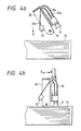
- the attachment plate 32b Upon the downward movement of the frame 36, the attachment plate 32b is in its vertical position as shown in FIGS. 3 and 4(a), and the sensor 33 can first detect the uppermost sheet surface in the cassette 17.
- the step motor 40 When the sensor 33 detects the uppermost sheet surface, the step motor 40 is de-energized to stop the downward movement of the frame 36. Then, the step motor 37 is energized, and its rotation is transmitted to the gears 38, 39 to rotate the shafts 34 about their own axes. The suction cups 31 are then moved downwardly along an arcuate path until they are held against the uppermost color developer sheet 16 as shown in FIG.4(b).
- the motor 61 is energized to move the piston 58 in the direction indicated by the arrow E.
- a vacuum is developed in each of the suction cups 31 to enable the suction cups 31 to attract the uppermost developer sheet 16.
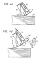
- the step motor 37 is reversed to turn the arm 32 through a predetermined angle about the shaft 34 in the direction indicated by the arrow A until the arm 32 assumes the position shown in FIG. 4(c).
- the arm 32 is not turned about the suction cups 31, but is turned about the shafts 34 positioned behind the suction cups 31. Therefore, the suction cups 31 are also turned about the shafts 34.
- the suction cups 31 attract the uppermost developer sheet 16 under suction and lifts the leading end portion of the developer sheet 16 off the next developer sheet 16. At this time, the uppermost developer sheet 16 is separated from the lower developer sheet 16 because of the stiffness of the upper developer sheet 16.
- the suction cups 31 can separate the uppermost developer sheet 16 since it is simply lifted off the lower developer sheet 16 without frictional engagement therewith. If the suction cups 31 were not turned but were operated only to attract the developer sheet 16, two or more developer sheets would be fed out at the same time when an electrostatic force acting on these sheets is greater than the weight of the developer sheet 16. Since the suction cups 31 are actually turned about the shafts 34, however, two or more developer sheets are prevented from being fed out together. An experiment conducted on the sheet feed mechanism 18 indicated than the uppermost developer sheet 16 could sufficiently be separated from the lower developer sheet 16 by the suction cups 31 when the arm 32 was turned through about 30°.
- step motor 40 is reversed to elevate the frames 36 and hence the elevator arm 32 in the direction indicated by the arrow C up to the position shown in FIG. 4(d) in which the leading end of the developer sheet 16 is positioned directly below the feed roller 19a.
- the pinch roller 19b is swung about its own axis in the direction indicated by the arrow G to pinch or nip the leading end of the developer sheet 16 between the pinch roller 19b(indicated by the two-dot-and-dash lines) and the feed roller 19a.
- the motor 61 of the evacuating-means 55 is reversed to move the piston 58 in the direction of the arrow F.
- the vacuum in the suction cups 31 is eliminated, and the developer sheet 16 is released from the suction cups 31.
- the step motor 40 is further energized to lift the frames 36 and the arm 32 by a certain distance to avoid engagement or interference between the suction cups 31 and the developer sheet 16 as it is fed along.
- the uppermost one of the stacked developer sheets 16 is separated and delivered into the sheet feed path.
- the roller 19d and the resist gate 19e are in the two-dot-and-dash position shown in FIG. 3, and hence the rollers 19c, 19d are spaced from each other.
- the developer sheet 16 is fed by the feed roller 19a and the pinch roller 19b until its leading end is engaged by the resist gate 19e, whereupon the leading end of the developer sheet 16 is properly aligned and corrected out of any skewed condition.
- the lever 74 is turned to displace the roller 19d against the roller 19c and pull the resist gate 19e out of the sheet feed path.
- the developer sheet 16 is now fed along the sheet feed path toward the pressure developing unit 13.
- a first vacuum just enough to attract and separate the uppermost developer sheet 16 from the sheet stack below is developed in the suction cups 31 when the suction cups 31 are held against the uppermost developer sheet 16, as shown in FIG.4(b). It was experimentally confirmed that the first vacuum should be intensive enough to draw a volume of 0.75 cc.
- a second vacuum greater than the first vacuum is developed in the suction cups 31, and thereafter or simultaneously, the frames 36 and the arm 32 are elevated in the direction indicated by the arrow C is FIG. 4(d). The second vacuum is large enough prevent the separated developer sheet 16 from dropping down while the arm 32 is being elevated. It was experimentally indicated that the second vacuum should be intensive enough to draw a volume of 3 cc.
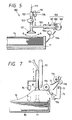
- FIG. 5 shows a sheet feed mechanism according to another embodiment of the present invention.
- the sheet feed mechanism generally designated at 100, includes a suction cup 101 mounted on the lower end of an arm 102 suspended by a spring 110 coupled to the upper end of the arm 102.
- the arm 102 can be moved by a cam 103 vertically in the directions indicated by the arrows C, D against the bias of the spring 110.
- the arm 102 can also be angularly moved by a cam 104 back and forth in the directions indicated by the arrows A, B against the bias of a spring 111 also connected to the upper end of the arm 102.
- An evacuating means 106 is connected through a tube 105 to an inner hole defined in the bottom of the suction cup 101.
- the evacuating means 106 comprises a cylinder 107, a piston 108 slidably fitted in the cylinder 107, and a crank 109 operatively coupled to the piston rod of the piston 108.
- the crank 109 When the crank 109 is rotated, the piston 108 is moved in the cylinder 107 in the direction indicated by the arrow E to develop a vacuum in the suction cup 101.
- the cam 103, the cam 104, and the crank 109 are mechanically coupled to each other so that they will operate in synchronism with each other with predetermined timing.
- FIGS. 6(a) through 6(e) illustrate the manner in which the sheet feed mechanism 100 operates.
- the cam 103 is first rotated to lower the arm 102 in the direction of the arrow D to bring the suction cup 101 into contact with the uppermost developer sheet 16 in the cassette 17 as shown in FIG. 6(b).
- the crank 109 is rotated to move the piston 108 in the direction of the arrow E thereby developing a vacuum in the cylinder 107 and hence the suction cup 101.
- the uppermost developer sheet 16 is therefore attracted by the suction cup 101 under the vacuum in the suction cup 101 (see FIG.3 (b)).
- the arm 102 is elevated by the cam 103 in the direction of the arrow C.
- the uppermost developer sheet 101 only or the uppermost developer sheet 16 and one or more lower developer sheets 16 are lifted up as shown in FIG. 6(c). Then, the arm 102 is turned by the cam 104 in the direction of the arrow B. Since the developer sheets 16 are positionally limited horizontally by the cassette 17, the uppermost developer sheet 16 attracted by the suction cup 101 is flexed, creating a gap between itself and any lower developer sheet or sheets which may have been lifted with the uppermost developer sheet 16. Any such lower developer sheet or sheets are therefore separated from the uppermost developer sheet 16 as shown in FIG. 6(d).
- the arm 102 is swung by the cam 104 in the direction of the arrow A to deliver the uppermost developer sheet 16 toward the rollers 19a, 19b as shown in FIG. 6(e).
- the sheet feed mechanism 100 is operated in the above cycle each time a sheet feed signal is supplied from the control unit of the copying machine shown in FIG. 1.
- a sheet feed mechanism 80 according to still another embodiment of the present invention will be described below with reference to FIG.7.
- the sheet feed mechanism 80 includes an array of suction cups (one shown) 81 mounted on a lifting/lowering device 82 which is vertically movable by a drive source (not shown). Each of the suction cups 81 is connected through a tube 83 to an evacuating means (not shown in FIG. 7) which may be similar to the evacuating means shown in FIG. 3 or 5.
- An uppermost sheet sensor 84 which may comprise a microswitch, for example, is mounted on the suction cup 81 by an arm 85.
- the suction cup 81 is positioned so that it attracts a leading end portion of the uppermost developer sheet 16.
- the stacked developer sheet 16 are placed on a sheet support 86 disposed in the cassette 17.
- the lifting/lowering device 82 is operated to lower the suction cups 81 in the direction indicated by the arrow D until the sensor 84 detects the upper surface of the uppermost developer sheet 16. Then, the lifting/lowering device 82 is shut off to stop the downward movement of the suction cups 81 which are now held against the upper surface of the uppermost developer sheet 16. Then, the evacuating means is actuated to develop a vacuum in the suction cups 81 to attract the uppermost developer sheet 16.
- the lifting/lowering device 82 is operated again to lift the suction cups 81 up to the position in which the leading end of the attracted developer sheet 16 is positioned directly beneath the feed roller 19a.
- the pinch roller 19b is moved toward the feed roller 19a in the direction of the arrow G to nip the leading end of the developer sheet 16 between the rollers 19a, 19b.
- the evacuating means is inactivated to release the developer sheet 16 from the suction cups 81.
- the developer sheet 16 is then fed along sheet feed path by the feed roller 19a.
- the sheet feed mechanism according to the present invention can be incorporated in any of various other image forming machines which employ other types of recording paper than the illustrated developer sheets 16.
Landscapes
- Engineering & Computer Science (AREA)
- Mechanical Engineering (AREA)
- Sheets, Magazines, And Separation Thereof (AREA)
Applications Claiming Priority (10)
| Application Number | Priority Date | Filing Date | Title |
|---|---|---|---|
| JP175938/88 | 1988-07-12 | ||
| JP63175938A JPH0223126A (ja) | 1988-07-12 | 1988-07-12 | 給紙装置及び給紙方法 |
| JP321621/88 | 1988-12-19 | ||
| JP32162188A JPH02169420A (ja) | 1988-12-19 | 1988-12-19 | 給紙装置 |
| JP32443688A JPH02169422A (ja) | 1988-12-21 | 1988-12-21 | 給紙方法 |
| JP324437/88 | 1988-12-21 | ||
| JP32443788A JPH02169423A (ja) | 1988-12-21 | 1988-12-21 | 給紙装置 |
| JP32443588A JPH02169421A (ja) | 1988-12-21 | 1988-12-21 | 給紙装置における紙分離方法 |
| JP324436/88 | 1988-12-21 | ||
| JP324435/88 | 1988-12-21 |
Publications (2)
| Publication Number | Publication Date |
|---|---|
| EP0351205A2 true EP0351205A2 (de) | 1990-01-17 |
| EP0351205A3 EP0351205A3 (de) | 1990-12-05 |
Family
ID=27528651
Family Applications (1)
| Application Number | Title | Priority Date | Filing Date |
|---|---|---|---|
| EP19890307067 Withdrawn EP0351205A3 (de) | 1988-07-12 | 1989-07-12 | Vorrichtung und Verfahren zum Zuführen eines Blattes |
Country Status (2)
| Country | Link |
|---|---|
| US (1) | US4968019A (de) |
| EP (1) | EP0351205A3 (de) |
Cited By (3)
| Publication number | Priority date | Publication date | Assignee | Title |
|---|---|---|---|---|
| EP0510925A3 (de) * | 1991-04-25 | 1992-11-19 | Minnesota Mining And Manufacturing Company | Adhäsionsbrecher für Blattstapel |
| JP2013196434A (ja) * | 2012-03-21 | 2013-09-30 | Asahi Seiko Co Ltd | シート状商品の払出装置 |
| WO2016116369A1 (de) * | 2015-01-19 | 2016-07-28 | Krones Aktiengesellschaft | Verfahren und vorrichtung zum separieren einzelner zwischenlagen von einem zwischenlagenstapel |
Families Citing this family (17)
| Publication number | Priority date | Publication date | Assignee | Title |
|---|---|---|---|---|
| JP2520312B2 (ja) * | 1989-10-12 | 1996-07-31 | 富士写真フイルム株式会社 | 枚葉動作制御装置 |
| JPH03147642A (ja) * | 1989-10-31 | 1991-06-24 | Brother Ind Ltd | 給紙装置 |
| JPH03162347A (ja) * | 1989-11-22 | 1991-07-12 | Minolta Camera Co Ltd | シート給送装置 |
| JPH03205235A (ja) * | 1989-12-29 | 1991-09-06 | Brother Ind Ltd | 給紙装置における紙分離方法 |
| US5207415A (en) * | 1990-01-17 | 1993-05-04 | Minolta Camera Kabushiki Kaisha | Paper feeding device |
| DK165527C (da) * | 1990-03-22 | 1993-04-26 | Eskofot As | Fremgangsmaade og apparat til enkeltvis transport af offsettrykplader |
| JPH07251966A (ja) * | 1994-03-10 | 1995-10-03 | Canon Inc | 記録または読み取り装置、及びシート吸着装置 |
| IT1279762B1 (it) * | 1995-03-01 | 1997-12-18 | Ast System Automation Stradi | Dispositivo per prelevare fogli da un pacco |
| US5991593A (en) * | 1996-09-04 | 1999-11-23 | Canon Kabushiki Kaisha | Sheet supplying apparatus of air absorbing type |
| US5967508A (en) * | 1997-11-24 | 1999-10-19 | Eastman Kodak Company | Film Sheet Picker assembly |
| AUPR292501A0 (en) * | 2001-02-07 | 2001-03-01 | Silverbrook Research Pty. Ltd. | A method and apparatus (ART100) |
| AUPR315301A0 (en) * | 2001-02-19 | 2001-03-15 | Silverbrook Research Pty. Ltd. | An Apparatus (ART102) |
| US6969060B2 (en) * | 2002-12-16 | 2005-11-29 | Creo Inc. | Sheet removal and conveying system |
| JP4338611B2 (ja) * | 2004-09-17 | 2009-10-07 | 富士フイルム株式会社 | フィルムシート枚葉機構及びこれを備えた熱現像記録装置 |
| US7161511B2 (en) * | 2005-06-03 | 2007-01-09 | General Electric Company | Linearization system and method |
| CA2895564C (en) | 2012-12-21 | 2020-03-24 | Short Brothers Plc | Fabric handling apparatus |
| CA2895569A1 (en) | 2012-12-21 | 2014-06-26 | Short Brothers Plc | Suction cup |
Family Cites Families (11)
| Publication number | Priority date | Publication date | Assignee | Title |
|---|---|---|---|---|
| DE134708C (de) * | ||||
| US1648493A (en) * | 1925-10-24 | 1927-11-08 | Clarence E Mckinsey | Feeding mechanism |
| DE724246C (de) * | 1936-11-21 | 1942-08-21 | Kleim & Ungerer | Durch Saugluft betaetigte Kippvorrichtung zur Bogentrennung |
| US4105198A (en) * | 1973-01-30 | 1978-08-08 | Agfa-Gevaert N.V. | Dispenser for sheet-like material |
| US4420150A (en) * | 1979-12-19 | 1983-12-13 | Ricoh Company, Ltd. | Apparatus and method for separating a single sheet from a stack and conveying it |
| JPS57184036A (en) * | 1981-05-06 | 1982-11-12 | Laurel Bank Mach Co Ltd | Conveying mechanism in separate conveyance device for bank note |
| US4394011A (en) * | 1981-08-20 | 1983-07-19 | Dalton Systems, Inc. | Automatic card or tag delivery apparatus |
| US4720227A (en) * | 1984-04-09 | 1988-01-19 | Eberle William J | Methods of and apparatus for stacking battery plates and the like |
| JPH0823665B2 (ja) * | 1985-12-02 | 1996-03-06 | 株式会社東芝 | シートフィルム搬送装置 |
| US4848764A (en) * | 1986-05-23 | 1989-07-18 | Fuji Photo Film Co., Ltd. | Sheet feeding mechanism |
| JPH0699048B2 (ja) * | 1988-02-18 | 1994-12-07 | ホリゾン・インターナショナル株式会社 | 給紙装置 |
-
1989
- 1989-07-10 US US07/377,137 patent/US4968019A/en not_active Expired - Fee Related
- 1989-07-12 EP EP19890307067 patent/EP0351205A3/de not_active Withdrawn
Cited By (3)
| Publication number | Priority date | Publication date | Assignee | Title |
|---|---|---|---|---|
| EP0510925A3 (de) * | 1991-04-25 | 1992-11-19 | Minnesota Mining And Manufacturing Company | Adhäsionsbrecher für Blattstapel |
| JP2013196434A (ja) * | 2012-03-21 | 2013-09-30 | Asahi Seiko Co Ltd | シート状商品の払出装置 |
| WO2016116369A1 (de) * | 2015-01-19 | 2016-07-28 | Krones Aktiengesellschaft | Verfahren und vorrichtung zum separieren einzelner zwischenlagen von einem zwischenlagenstapel |
Also Published As
| Publication number | Publication date |
|---|---|
| EP0351205A3 (de) | 1990-12-05 |
| US4968019A (en) | 1990-11-06 |
Similar Documents
| Publication | Publication Date | Title |
|---|---|---|
| US4968019A (en) | Sheet feed mechanism and method of feeding sheet | |
| US5041879A (en) | Sheet supplying device having control unit for sheet supplying operation | |
| JPS63230435A (ja) | シ−ト供給装置 | |
| EP0381382A2 (de) | Vorrichtung zum Zuführen von Bögen mit Anlage zum Vermeiden von Staub und Verfahren zum Reinigen der Bogenzuführvorrichtung | |
| US5005818A (en) | Sheet feed device having a sheet cassette locking mechanism | |
| US5075939A (en) | Sheet supplying device | |
| US5080344A (en) | Sheet supplying device for sheet supplying operation | |
| EP0350310A2 (de) | Bildaufnahmegerät | |
| EP0835832A2 (de) | Blattzufuhrvorrichtung | |
| JPH02169420A (ja) | 給紙装置 | |
| US4994848A (en) | Imaging device | |
| JP3273660B2 (ja) | 複写機 | |
| JPH03147640A (ja) | 給紙装置 | |
| JPH0420438A (ja) | 給紙装置 | |
| JPH02169421A (ja) | 給紙装置における紙分離方法 | |
| JPH03215860A (ja) | カラー画像形成方法 | |
| JP2720495B2 (ja) | 画像形成装置 | |
| JPH02204235A (ja) | 給紙装置 | |
| JPS5828565B2 (ja) | フクシヤソウチ | |
| JPH10310285A (ja) | シート給送装置及びこれを備えた画像形成装置 | |
| JPH03147639A (ja) | 給紙装置 | |
| JPH1111691A (ja) | 給紙装置 | |
| JPH03137643A (ja) | 給紙装置 | |
| JP3499306B2 (ja) | 色調整フィルターの駆動機構 | |
| JPH02169422A (ja) | 給紙方法 |
Legal Events
| Date | Code | Title | Description |
|---|---|---|---|
| PUAI | Public reference made under article 153(3) epc to a published international application that has entered the european phase |
Free format text: ORIGINAL CODE: 0009012 |
|
| AK | Designated contracting states |
Kind code of ref document: A2 Designated state(s): DE FR GB |
|
| PUAL | Search report despatched |
Free format text: ORIGINAL CODE: 0009013 |
|
| AK | Designated contracting states |
Kind code of ref document: A3 Designated state(s): DE FR GB |
|
| 17P | Request for examination filed |
Effective date: 19901228 |
|
| STAA | Information on the status of an ep patent application or granted ep patent |
Free format text: STATUS: THE APPLICATION HAS BEEN WITHDRAWN |
|
| 18W | Application withdrawn |
Withdrawal date: 19920715 |