EP0353998A1 - Tête magnétique - Google Patents
Tête magnétique Download PDFInfo
- Publication number
- EP0353998A1 EP0353998A1 EP89307819A EP89307819A EP0353998A1 EP 0353998 A1 EP0353998 A1 EP 0353998A1 EP 89307819 A EP89307819 A EP 89307819A EP 89307819 A EP89307819 A EP 89307819A EP 0353998 A1 EP0353998 A1 EP 0353998A1
- Authority
- EP
- European Patent Office
- Prior art keywords
- magnetic
- glass
- core
- gap
- bonding
- Prior art date
- Legal status (The legal status is an assumption and is not a legal conclusion. Google has not performed a legal analysis and makes no representation as to the accuracy of the status listed.)
- Granted
Links
Images


Classifications
-
- G—PHYSICS
- G11—INFORMATION STORAGE
- G11B—INFORMATION STORAGE BASED ON RELATIVE MOVEMENT BETWEEN RECORD CARRIER AND TRANSDUCER
- G11B5/00—Recording by magnetisation or demagnetisation of a record carrier; Reproducing by magnetic means; Record carriers therefor
- G11B5/127—Structure or manufacture of heads, e.g. inductive
- G11B5/187—Structure or manufacture of the surface of the head in physical contact with, or immediately adjacent to the recording medium; Pole pieces; Gap features
- G11B5/1875—"Composite" pole pieces, i.e. poles composed in some parts of magnetic particles and in some other parts of magnetic metal layers
- G11B5/1877—"Composite" pole pieces, i.e. poles composed in some parts of magnetic particles and in some other parts of magnetic metal layers including at least one magnetic thin film
- G11B5/1878—"Composite" pole pieces, i.e. poles composed in some parts of magnetic particles and in some other parts of magnetic metal layers including at least one magnetic thin film disposed immediately adjacent to the transducing gap, e.g. "Metal-In-Gap" structure
-
- G—PHYSICS
- G11—INFORMATION STORAGE
- G11B—INFORMATION STORAGE BASED ON RELATIVE MOVEMENT BETWEEN RECORD CARRIER AND TRANSDUCER
- G11B5/00—Recording by magnetisation or demagnetisation of a record carrier; Reproducing by magnetic means; Record carriers therefor
- G11B5/127—Structure or manufacture of heads, e.g. inductive
- G11B5/187—Structure or manufacture of the surface of the head in physical contact with, or immediately adjacent to the recording medium; Pole pieces; Gap features
- G11B5/21—Structure or manufacture of the surface of the head in physical contact with, or immediately adjacent to the recording medium; Pole pieces; Gap features the pole pieces being of ferrous sheet metal or other magnetic layers
-
- G—PHYSICS
- G11—INFORMATION STORAGE
- G11B—INFORMATION STORAGE BASED ON RELATIVE MOVEMENT BETWEEN RECORD CARRIER AND TRANSDUCER
- G11B5/00—Recording by magnetisation or demagnetisation of a record carrier; Reproducing by magnetic means; Record carriers therefor
- G11B5/127—Structure or manufacture of heads, e.g. inductive
- G11B5/187—Structure or manufacture of the surface of the head in physical contact with, or immediately adjacent to the recording medium; Pole pieces; Gap features
- G11B5/23—Gap features
- G11B5/232—Manufacture of gap
Definitions
- the present invention relates to a magnetic head for use in a magnetic recording and reproducing apparatus such as a VTR.
- a magnetic head core is composed of two separate core parts which are bonded together at gap surfaces. In order to achieve a high reliability,the bonding of the core parts is usually conducted by fusion of a glass.
- Fig. 3 is a perspective view of a head made of a known metallic magnetic material. The head core 11, which is made of a metallic magnetic material, is clamped by a pair of substrates 12. A magnetic gap is composed of a non-magnetic material 14 and the bonding of the core parts at the gap surfaces is accomplished by fusion of bonding glass 15 which fills grooves or recesses provided along a track.
- an amorphous alloy When an amorphous alloy is used as the metallic magnetic material of the magnetic head core, it is not allowed to use such a bonding glass having a high melting point as that used in conventional ferrite cores, considering the magnetic characteristics of the amorphous alloy.
- an amorphous alloy exhibits magnetization which becomes zero at the Curie point Tc and increases again when the temperature is raised to or beyond the crystallization temperature Tx, as shown in Fig. 4.
- the magnetic permeability of the magnetic head In order to obtain excellent magnetic head characteristics, it is preferred that the magnetic permeability of the magnetic head is high. In order to obtain a high magnetic permeability, it is necessary to conduct a heat treatment at a temperature which is not lower than Tc and not higher than Tx, so as to eliminate any magnetic an isotropy in the magnetic film.
- bonding glass having high melting point also is inhibited when the core is made of sendust or permalloy, because heating of such metallic magnetic material causes a separation of the core from the substrate at high temperature due to difference in the thermal expansion coefficient.
- Magnetic head which will be referred to as MIG heads have been known in which a metallic magnetic material is used only in the region near the magnetic gap.
- This type of magnetic head also requires the use of bonding glass having a low melting point because a too high bonding temperature causes a diffusion between the metallic magnetic material and the ferrite to form a reaction layer which provides an effect resembling that of the gap.
- an object of the present invention is to provide a magnetic head which is capable of overcoming the above-described problems of the prior art.
- a magnetic head having a head core made of a metallic magnetic material and composed of two parts which are bonded together across a magnetic gap, characterized in that the magnetic gap is filled with a structure having a crystallized glass of a low melting point and sandwiched between layers of a non-magnetic material, so that the bonding of the head core parts across the magnetic gap is achieved by the crystallized glass of a low melting point while the layers of the non-magnetic material prevent reaction between the metallic magnetic material of the core half part and the crystallized glass of low melting point, whereby a high mechanical strength of the magnetic head and high precision of the narrow magnetic gap are attained.
- the glass of a low melting point still in amorphous state, held on the surfaces of the non-magnetic material layers on the gap surfaces of the core parts, is molten so as to bond two core parts to each other.
- the glass is then crystallized so as to enhance its strength.
- the non-magnetic material layers existing between both core parts and the low-melting-point crystallized glass effectively prevent reaction between the metallic magnetic core material and the glass, thereby preventing the magnetic characteristics of the core from being impaired.
- the core parts it is therefore possible to bond the core parts at such a low temperature as that used for amorphous glass, without allowing any reaction to take place between the glass and the metallic magnetic core material.
- the glass develops a high bonding strength so as to enhance the bonding power of the head core parts, while attaining a high precision of the size of the narrow magnetic gap, thereby to offer a remarkable improvement in the yield and reliability of the magnetic heads.
- a magnetic head core 1 which is composed of two parts, is made of a metallic magnetic material which is in this embodiment assumed to be an amorphous alloy.
- the magnetic head core 1 is sandwiched between substrates 2.
- the two parts of the magnetic head core 1 are bonded together at their gap surfaces, i.e., the surfaces facing a narrow magnetic gap, by fusion and crystallization of a low-melting-point glass 3 provided between layers 4 of non-magnetic material provided on the gap surfaces of the core parts of the head core 1.
- the low-melting-point crystallized glass used in this embodiment is a lead-containing glass which has a softening point of about 440°C.
- Numeral 6 denotes a layer of bonding glass.
- an amorphous alloy layer 1 which is to be used as the magnetic head core part, is formed on the surface of a substrate 2 by a thin-film forming technique such as spattering.
- a layer 6 of bonding glass is formed on the side of the substrate 2 opposite to the amorphous alloy layer, thus forming an element.
- a low-melting-point crystallizable glass is used as the bonding glass.
- the amorphous alloy used in this embodiment has, for example, a saturation magnetic flux density of 8300 gauss, a crystallization temperature Tx of 575°C and a Curie temperature Tc of 500°C.
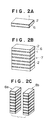
- a plurality of elements shown in Fig. 1 are stacked as shown in Fig. 2b and pressed and heated so that a laminate block is formed.
- the bonding glass layer 6 is crystallized so that the softening point is raised by about 100°C as compared with the amorphous state of this glass, so that the bonding layers are not softened or peeled off when being subjected to a subsequent heat treatment.
- the laminate block 7 is processed to form a pair of core bars 8a and 8b as shown in Fig. 2c.
- a winding groove 10 for receiving windings is formed in the gap surface 9a of one 8a of the core bars, and the gap surfaces 9a, 9b of both core bars 8a, 8b are polished into highly smooth state.
- a layer or film 4 of a non-magnetic material such as SiO2 or a high-melting-point glass is formed on the smoothed gap surfaces 9a and 9b to a predetermined thickness by, for example, spattering.
- a layer of a low-melting-point crystallizable glass 3 is formed to a predetermined thickness by, for example, spattering on the film 4 of the non-magnetic material on each core bar.
- the glass layer 3 formed on the surface of the non-magnetic material layer 4 is still in amorphous state because it is formed by spattering.
- the thickness of the non-magnetic material layer 4 and the thickness of the low-melting-point glass layer 3 are determined to be not smaller than 300 ⁇ and not smaller than 100 ⁇ , respectively.
- the layers of the low-melting-point crystallizable glass 3 are molten and fused and then starts to be crystallized, whereby the core bars 8a and 8b can be bonded together at their gap surfaces with a high mechanical bonding strength.
- the low-melting-point crystallizable glass tends to react with the amorphous alloy of the core material during the heat treatment so as to become fragile.
- This problems is overcome by the present invention by virtue of the presence of the layer of a non-magnetic material such as SiO2 or a high-melting-point glass formed between the crystallizable glass 3 and the gap surfaces of the two head parts so as to prevent reaction between the glass and the amorphous alloy used as the core material.
- the magnetic head of the invention produced by the method as described, offers a high yield and a high degree of precision of the gap size, thereby improving the reliability of the magnetic head.
- the invention can equally be applied to a MIG head in which metallic magnetic material is arranged only in the vicinity of the magnetic gap, although a magnetic head of the described embodiment has a magnetic core wholly made of a metallic magnetic material and sandwiched between substrates.
Landscapes
- Engineering & Computer Science (AREA)
- Manufacturing & Machinery (AREA)
- Magnetic Heads (AREA)
Applications Claiming Priority (2)
| Application Number | Priority Date | Filing Date | Title |
|---|---|---|---|
| JP63194093A JPH0775053B2 (ja) | 1988-08-03 | 1988-08-03 | 磁気ヘッド及びその製造方法 |
| JP194093/88 | 1988-08-03 |
Publications (2)
| Publication Number | Publication Date |
|---|---|
| EP0353998A1 true EP0353998A1 (fr) | 1990-02-07 |
| EP0353998B1 EP0353998B1 (fr) | 1994-02-09 |
Family
ID=16318832
Family Applications (1)
| Application Number | Title | Priority Date | Filing Date |
|---|---|---|---|
| EP89307819A Expired - Lifetime EP0353998B1 (fr) | 1988-08-03 | 1989-08-01 | Tête magnétique |
Country Status (3)
| Country | Link |
|---|---|
| EP (1) | EP0353998B1 (fr) |
| JP (1) | JPH0775053B2 (fr) |
| DE (1) | DE68912987T2 (fr) |
Citations (1)
| Publication number | Priority date | Publication date | Assignee | Title |
|---|---|---|---|---|
| EP0221697A2 (fr) * | 1985-10-14 | 1987-05-13 | Hitachi, Ltd. | Tête magnétique en alliage magnétique amorphe et son procédé de fabrication |
Family Cites Families (4)
| Publication number | Priority date | Publication date | Assignee | Title |
|---|---|---|---|---|
| JPS55108922A (en) * | 1979-02-09 | 1980-08-21 | Tdk Corp | Magnetic head |
| JPS5654622A (en) * | 1979-10-12 | 1981-05-14 | Hitachi Ltd | Magnetic head and its manufacture |
| NL8202059A (nl) * | 1982-05-19 | 1983-12-16 | Philips Nv | Glas gekitte magneetkop en werkwijze voor zijn vervaardiging. |
| JPS62281111A (ja) * | 1986-05-30 | 1987-12-07 | Toshiba Corp | 磁気ヘツド |
-
1988
- 1988-08-03 JP JP63194093A patent/JPH0775053B2/ja not_active Expired - Lifetime
-
1989
- 1989-08-01 DE DE68912987T patent/DE68912987T2/de not_active Expired - Fee Related
- 1989-08-01 EP EP89307819A patent/EP0353998B1/fr not_active Expired - Lifetime
Patent Citations (1)
| Publication number | Priority date | Publication date | Assignee | Title |
|---|---|---|---|---|
| EP0221697A2 (fr) * | 1985-10-14 | 1987-05-13 | Hitachi, Ltd. | Tête magnétique en alliage magnétique amorphe et son procédé de fabrication |
Non-Patent Citations (1)
| Title |
|---|
| PATENT ABSTRACTS OF JAPAN * |
Also Published As
| Publication number | Publication date |
|---|---|
| JPH0244509A (ja) | 1990-02-14 |
| JPH0775053B2 (ja) | 1995-08-09 |
| DE68912987D1 (de) | 1994-03-24 |
| EP0353998B1 (fr) | 1994-02-09 |
| DE68912987T2 (de) | 1994-05-19 |
Similar Documents
| Publication | Publication Date | Title |
|---|---|---|
| US4947542A (en) | Method of making a crystallized glass-bonded amorphous metal magnetic film-non-magnetic substrate magnetic head | |
| US5170301A (en) | Magnetic head having core parts joined by low-melting point crystallized glass with composite gap | |
| US3629519A (en) | Magnetic heads with poles joined by molecular transport bonding | |
| US4755898A (en) | Amorphous magnetic head | |
| EP0353998B1 (fr) | Tête magnétique | |
| US5208971A (en) | Process of manufacturing a magnetic head | |
| JPH08329409A (ja) | 磁気ヘッド | |
| JPS60261006A (ja) | 磁気ヘツドの製造方法 | |
| JP3055321B2 (ja) | 磁気ヘッドと製造法 | |
| JPH01109504A (ja) | 磁気ヘッド | |
| JPH0766491B2 (ja) | 磁気ヘツド | |
| JP2001076310A (ja) | 磁気ヘッド及びその製造方法 | |
| JPH10283610A (ja) | 磁気ヘッド及びその製造方法 | |
| JPS58158022A (ja) | 磁気ヘツドコアの製造方法 | |
| JPS6095713A (ja) | 磁気ヘツドの製造方法 | |
| JPH1091913A (ja) | 磁気ヘッドの製造方法 | |
| JPH0628613A (ja) | 複合型磁気ヘッド | |
| JPS61192007A (ja) | 磁気ヘツドの製造方法 | |
| JPS62139109A (ja) | 磁気ヘツド及びその製造方法 | |
| JPH0773407A (ja) | 磁気ヘッドチップの製造方法 | |
| JPS63249913A (ja) | 磁気ヘツド | |
| JPH0328724B2 (fr) | ||
| JPH05101360A (ja) | 薄膜磁気ヘツドスライダとその製造方法 | |
| JPH04319510A (ja) | 複合ヘッドの製造方法 | |
| JPH01317211A (ja) | 磁気ヘッド |
Legal Events
| Date | Code | Title | Description |
|---|---|---|---|
| PUAI | Public reference made under article 153(3) epc to a published international application that has entered the european phase |
Free format text: ORIGINAL CODE: 0009012 |
|
| AK | Designated contracting states |
Kind code of ref document: A1 Designated state(s): DE FR GB |
|
| 17P | Request for examination filed |
Effective date: 19900424 |
|
| 17Q | First examination report despatched |
Effective date: 19911217 |
|
| GRAA | (expected) grant |
Free format text: ORIGINAL CODE: 0009210 |
|
| AK | Designated contracting states |
Kind code of ref document: B1 Designated state(s): DE FR GB |
|
| REF | Corresponds to: |
Ref document number: 68912987 Country of ref document: DE Date of ref document: 19940324 |
|
| ET | Fr: translation filed | ||
| PLBE | No opposition filed within time limit |
Free format text: ORIGINAL CODE: 0009261 |
|
| STAA | Information on the status of an ep patent application or granted ep patent |
Free format text: STATUS: NO OPPOSITION FILED WITHIN TIME LIMIT |
|
| 26N | No opposition filed | ||
| REG | Reference to a national code |
Ref country code: GB Ref legal event code: IF02 |
|
| REG | Reference to a national code |
Ref country code: GB Ref legal event code: 746 Effective date: 20031002 |
|
| REG | Reference to a national code |
Ref country code: FR Ref legal event code: D6 |
|
| PGFP | Annual fee paid to national office [announced via postgrant information from national office to epo] |
Ref country code: DE Payment date: 20070726 Year of fee payment: 19 |
|
| PGFP | Annual fee paid to national office [announced via postgrant information from national office to epo] |
Ref country code: GB Payment date: 20070801 Year of fee payment: 19 |
|
| PGFP | Annual fee paid to national office [announced via postgrant information from national office to epo] |
Ref country code: FR Payment date: 20070808 Year of fee payment: 19 |
|
| GBPC | Gb: european patent ceased through non-payment of renewal fee |
Effective date: 20080801 |
|
| REG | Reference to a national code |
Ref country code: FR Ref legal event code: ST Effective date: 20090430 |
|
| PG25 | Lapsed in a contracting state [announced via postgrant information from national office to epo] |
Ref country code: FR Free format text: LAPSE BECAUSE OF NON-PAYMENT OF DUE FEES Effective date: 20080901 Ref country code: DE Free format text: LAPSE BECAUSE OF NON-PAYMENT OF DUE FEES Effective date: 20090303 |
|
| PG25 | Lapsed in a contracting state [announced via postgrant information from national office to epo] |
Ref country code: GB Free format text: LAPSE BECAUSE OF NON-PAYMENT OF DUE FEES Effective date: 20080801 |