EP0360280A2 - Méthode et dispositif d'enregistrement par transfert thermique - Google Patents
Méthode et dispositif d'enregistrement par transfert thermique Download PDFInfo
- Publication number
- EP0360280A2 EP0360280A2 EP89117562A EP89117562A EP0360280A2 EP 0360280 A2 EP0360280 A2 EP 0360280A2 EP 89117562 A EP89117562 A EP 89117562A EP 89117562 A EP89117562 A EP 89117562A EP 0360280 A2 EP0360280 A2 EP 0360280A2
- Authority
- EP
- European Patent Office
- Prior art keywords
- ink sheet
- amount
- take
- recording medium
- conveying
- Prior art date
- Legal status (The legal status is an assumption and is not a legal conclusion. Google has not performed a legal analysis and makes no representation as to the accuracy of the status listed.)
- Granted
Links
- 238000012546 transfer Methods 0.000 title claims abstract description 42
- 238000000034 method Methods 0.000 title claims description 34
- 230000008859 change Effects 0.000 claims abstract description 25
- 238000012545 processing Methods 0.000 claims description 62
- 230000005540 biological transmission Effects 0.000 claims description 16
- 238000004804 winding Methods 0.000 claims description 3
- 230000005284 excitation Effects 0.000 description 31
- 239000010410 layer Substances 0.000 description 28
- 230000003247 decreasing effect Effects 0.000 description 20
- 230000007246 mechanism Effects 0.000 description 15
- 230000004048 modification Effects 0.000 description 12
- 238000012986 modification Methods 0.000 description 12
- 238000010586 diagram Methods 0.000 description 10
- 230000004044 response Effects 0.000 description 6
- 239000011247 coating layer Substances 0.000 description 4
- 238000010438 heat treatment Methods 0.000 description 4
- 239000000463 material Substances 0.000 description 4
- 238000010008 shearing Methods 0.000 description 4
- 239000011248 coating agent Substances 0.000 description 3
- 238000000576 coating method Methods 0.000 description 3
- 238000012937 correction Methods 0.000 description 3
- -1 polyethylene Polymers 0.000 description 3
- 239000004698 Polyethylene Substances 0.000 description 2
- 239000004760 aramid Substances 0.000 description 2
- 229920003235 aromatic polyamide Polymers 0.000 description 2
- 238000001514 detection method Methods 0.000 description 2
- 229920002313 fluoropolymer Polymers 0.000 description 2
- 230000006870 function Effects 0.000 description 2
- 229920006267 polyester film Polymers 0.000 description 2
- 229920000573 polyethylene Polymers 0.000 description 2
- 229920005989 resin Polymers 0.000 description 2
- 239000011347 resin Substances 0.000 description 2
- VZXTWGWHSMCWGA-UHFFFAOYSA-N 1,3,5-triazine-2,4-diamine Chemical compound NC1=NC=NC(N)=N1 VZXTWGWHSMCWGA-UHFFFAOYSA-N 0.000 description 1
- 229920002284 Cellulose triacetate Polymers 0.000 description 1
- 239000004677 Nylon Substances 0.000 description 1
- 239000004642 Polyimide Substances 0.000 description 1
- NNLVGZFZQQXQNW-ADJNRHBOSA-N [(2r,3r,4s,5r,6s)-4,5-diacetyloxy-3-[(2s,3r,4s,5r,6r)-3,4,5-triacetyloxy-6-(acetyloxymethyl)oxan-2-yl]oxy-6-[(2r,3r,4s,5r,6s)-4,5,6-triacetyloxy-2-(acetyloxymethyl)oxan-3-yl]oxyoxan-2-yl]methyl acetate Chemical compound O([C@@H]1O[C@@H]([C@H]([C@H](OC(C)=O)[C@H]1OC(C)=O)O[C@H]1[C@@H]([C@@H](OC(C)=O)[C@H](OC(C)=O)[C@@H](COC(C)=O)O1)OC(C)=O)COC(=O)C)[C@@H]1[C@@H](COC(C)=O)O[C@@H](OC(C)=O)[C@H](OC(C)=O)[C@H]1OC(C)=O NNLVGZFZQQXQNW-ADJNRHBOSA-N 0.000 description 1
- 239000000853 adhesive Substances 0.000 description 1
- 230000001070 adhesive effect Effects 0.000 description 1
- 230000015572 biosynthetic process Effects 0.000 description 1
- 239000003990 capacitor Substances 0.000 description 1
- 239000006229 carbon black Substances 0.000 description 1
- 235000013869 carnauba wax Nutrition 0.000 description 1
- 239000004203 carnauba wax Substances 0.000 description 1
- 238000006243 chemical reaction Methods 0.000 description 1
- 238000004040 coloring Methods 0.000 description 1
- 238000011109 contamination Methods 0.000 description 1
- 230000009189 diving Effects 0.000 description 1
- 230000000694 effects Effects 0.000 description 1
- 239000003822 epoxy resin Substances 0.000 description 1
- 239000004744 fabric Substances 0.000 description 1
- 230000007774 longterm Effects 0.000 description 1
- 239000000203 mixture Substances 0.000 description 1
- 229920001778 nylon Polymers 0.000 description 1
- 230000003287 optical effect Effects 0.000 description 1
- 239000012188 paraffin wax Substances 0.000 description 1
- 239000002245 particle Substances 0.000 description 1
- 239000002985 plastic film Substances 0.000 description 1
- 229920003207 poly(ethylene-2,6-naphthalate) Polymers 0.000 description 1
- 229920000647 polyepoxide Polymers 0.000 description 1
- 229920000728 polyester Polymers 0.000 description 1
- 239000011112 polyethylene naphthalate Substances 0.000 description 1
- 229920001721 polyimide Polymers 0.000 description 1
- 229920000915 polyvinyl chloride Polymers 0.000 description 1
- 239000004800 polyvinyl chloride Substances 0.000 description 1
- 238000003825 pressing Methods 0.000 description 1
- 230000002035 prolonged effect Effects 0.000 description 1
- 230000035945 sensitivity Effects 0.000 description 1
- 229920002050 silicone resin Polymers 0.000 description 1
- 125000006850 spacer group Chemical group 0.000 description 1
- 239000001993 wax Substances 0.000 description 1
Images


Classifications
-
- B—PERFORMING OPERATIONS; TRANSPORTING
- B41—PRINTING; LINING MACHINES; TYPEWRITERS; STAMPS
- B41J—TYPEWRITERS; SELECTIVE PRINTING MECHANISMS, i.e. MECHANISMS PRINTING OTHERWISE THAN FROM A FORME; CORRECTION OF TYPOGRAPHICAL ERRORS
- B41J17/00—Mechanisms for manipulating page-width impression-transfer material, e.g. carbon paper
- B41J17/02—Feeding mechanisms
- B41J17/04—Feed dependent on the record-paper feed, e.g. both moved at the same time
Definitions
- the present invention relates to a thermal transfer recording apparatus for transferring an ink of an ink sheet to a recording medium to record an image on the recording medium.
- the thermal transfer recording apparatuses include facsimile apparatuses, electronic typewriters, copying machines, printers, and the like.
- a thermal transfer printer employs an ink sheet in which a heat-melt (or heat-sublimate, or the like) ink is coated on a base film.
- the ink sheet is selectively head by a thermal head in correspondence with an image signal, and a melted (sublimated) ink is transferred onto recording paper or sheet to perform image recording.
- the ink sheet is one from which an ink is completely transferred to recording paper in single image recording (i.e., a so-called one-time sheet)
- the ink sheet must be conveyed by a distance corresponding to a recording length after a one-character or one-line image is recorded, so that a nonused portion of the ink sheet must be reliably conveyed to the next recording position. For this reason, an amount of use of the ink sheet is increased, and running cost of a thermal transfer printer tends to be increased as compared to a conventional thermal printer which records an image on a thermal sheet.
- thermal transfer printers each of which conveys recording paper and an ink sheet in the same direction to have a speed difference therebetween have been proposed.
- an ink sheet capable of performing a plurality of times (n) image recording operations (multi-print sheet) is known. If this ink sheet is used, when a recording operation is continuously performed over a recording length L, a conveying length of an ink sheet which is conveyed after every image recording operation or during image recording can be decreased to be smaller than the length L (L/n : n > 1).
- This recording system will be referred to as a multi-print system.
- the ink sheet When the multi-print system is realized by such an ink sheet, the ink sheet must always be conveyed by a constant distance with respect to a conveying operation of a predetermined length of recording paper.
- this conveying control if the conveying operation of the ink sheet is controlled by rotation of a support shaft of a take-up roller of an ink sheet, the diameter of the take-up roller for taking up the ink sheet is increased by the taken-up ink sheet.
- the take-up roller is controlled to be rotated by the same amount, the conveying distance of the ink sheet at the end of the take-up operation is changed from one at the beginning of the take-up operation. For this reason, the ink sheet is clamped by a capstan roller, a pinch roller, and the like, and is conveyed upon rotation of these rollers.
- a platen roller is rotated to convey the recording paper by one line in a subscan direction.
- a motor for conveying an ink sheet is rotated by one step, the ink sheet is taken up by a take-up roller, and is also conveyed by one line.
- a thermal head is energized to perform transfer recording, so that one-line image data is recorded on recording paper.
- the conveying operations of the recording paper and the ink sheet and image recording processing by the thermal head are repetitively performed, thereby sequentially transferring and recording image data on the recording paper.
- the motor for conveying the ink sheet drives the rotating shaft of the take-up roller, and is always rotated at a constant angular velocity. For this reason, when the take-up amount of the ink sheet is increased, the diameter of the take-up roller is increased. Even if the motor for conveying the ink sheet is rotated at the same angular velocity, the moving speed of the ink sheet is undesirably increased.
- Figs. 1 to 4 show a case wherein a thermal transfer printer using an embodiment of the present invention is applied to a facsimile apparatus.
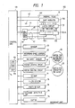
- Fig. 1 is a block diagram showing electrical connections between a control unit and a mechanism unit
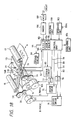
- Fig. 2 is a perspective view showing a conveying mechanism of recording paper and an ink sheet
- Fig. 3A is a side sectional view of the facsimile apparatus
- Fig. 3B is a perspective view of an outer appearance of the apparatus
- Fig. 4 is a schematic block diagram of the facsimile apparatus.
- a reading unit 100 photoelectrically reads an original, and outputs it as a digital image signal to a control unit 101.
- the reading unit 100 comprises an original conveying motor, a CCD image sensor, and the like.
- the arrangement of the control unit 101 will be described below.
- the control unit 101 comprises a line memory 110 for storing image data for each line.
- the line memory 110 stores one-line image data supplied from the reading unit 100 in an original transmission or copying mode, and stores one-line data of decoded received image data in an image data reception mode.
- the stored data is output to a recording unit 102 to perform image formation.
- An encode/decode unit 111 encodes image data to be transmitted by MH coding, and decodes received encoded image data to convert it to image data.
- a buffer memory 112 stores encoded image data to be transmitted or received encoded image data. These sections of the control unit 101 are controlled by a CPU 113 such as a microprocessor.
- the control unit 101 also includes a ROM 114 for storing a control program of the CPU 113, and various data, a RAM 115 serving as a work area of the CPU 113 to temporarily store various data, and the like.
- the recording unit 102 comprises a thermal line head, and records an image on recording paper by a thermal transfer recording method.
- An operation unit 103 includes various function instruction keys such as a transmission start key, input keys of telephone numbers, a switch 103a for indicating a type of ink sheet to be used, and the like. When the switch 103a is ON, it indicates that a multi-print ink sheet is loaded; when it is OFF, it indicates that a conventional one-time ink sheet is loaded.
- An indicating unit 104 is normally arranged in the operation unit 103, and indicates various functions and states of the apparatus.
- a voltage source 105 supplies power to the entire apparatus.
- the apparatus also includes a modem (modulator/demodulator) 106, a network control unit (NCU) 107, and a telephone set 108.
- a paper roll 10 is obtained by winding recording paper 11 as normal paper in a cylindrical shape.
- the paper roll 10 is rotatably housed in the apparatus so that the recording paper 11 can be fed to a thermal head 13 portion upon rotation of a platen roller 12 in a direction of an arrow.
- the paper roll 10 is detachably loaded in a paper roll loading portion 10b.
- the platen roller 12 conveys the recording paper 11 in a direction of an arrow b, and presses an ink sheet 13 and the recording paper 11 between itself and heat generating elements 132 of the thermal head 13.
- the recording paper 11 which is subjected to image recording upon heating of the thermal head 13 is conveyed by further rotation of the platen roller 12 in a direction of exhaust rollers 16a and 1.6b.
- the recording paper 11 is cut in units of pages upon engagement of cutters 15a and 15b, and a one-page sheet is exhausted.
- An ink sheet supply roller 17 winds the ink sheet 14 therearound.
- An ink sheet take-up roller 18 is driven by a motor 25 (to be described later) for the ink sheet, and takes up the ink sheet in a direction of an arrow a.
- the ink sheet supply roller 17 and the ink sheet take-up roller 18 are detachably loaded in an ink sheet loading portion 70 in the apparatus main body.
- a sensor 19 is used to detect a remain and a conveying speed of the ink sheet 14.
- An ink sheet sensor 20 detects the presence/absence of the ink sheet 14.
- Springs 21 press the thermal head 13 against the platen roller 12 through the recording paper 11 and the ink sheet 14.
- a recording sheet or paper sensor 22 detects the presence/absence of the recording paper.
- a sensor 23 detects a diameter of the take-up roller 18.
- a roller 72 guides the ink sheet 14.
- a light source 30 radiates light on an original 32.
- Light reflected by the original 32 is input to a CCD sensor 31 through an optical system (mirrors 50 and 51 and a lens 52), and is converted to an electrical signal.
- the original 32 is conveyed by conveying rollers 53, 54, 55, and 56 driven by an original conveying motor (not shown) in correspondence with a reading speed of the original 32.
- the original 32 is placed on an original table 57.
- a plurality of originals 32 placed on the original table 57 are separated one by one in cooperation of the conveying roller 54 and a pressing/separating segment 58 while being guided by a slider 57a, and each original is conveyed to the reading unit 100. After the reading operation, the original is exhausted onto a tray 77.
- a control board 41 constitutes a principal part of the control unit 101, and outputs various control signals to respective units of the apparatus.
- the reading unit 100 also includes the voltage source unit 105, the modem board unit 106, and the NCU board unit 107.
- Fig. 2 shows the conveying mechanism of the ink sheet 14 and the recording paper 11 in detail.
- a motor 24 drives the platen roller 12 to convey the recording paper in a direction of the arrow b opposite to the direction of the arrow a.
- the motor 25 conveys the ink sheet 14 in the direction of the arrow a.
- Transmission gears 26 and 27 transmit rotation of the motor 24 to the platen roller 12.
- Transmission gears 28 and 29 transmit rotation of the motor 25 to the take-up roller 18.
- a worm gear 33 reduces a rotating amount of a rotating shaft 18a of the take-up roller 18, and transmits its rotation to a disc 34 for indicating a take-up amount of the ink sheet 14.
- the worm gear 33 has a disc portion 33a meshed with a threaded portion 8b of the rotating shaft 18a, and a column portion 33b meshed with the disc 34.
- Photosensors 35 and 36 detect slits 37-1 and 37-2 to detect the rotational position of the disc 34.
- Each of the photosensors 35 and 36 comprises a photodiode for outputting light and a sensor for detecting light passing through the slit 37-1 or 37-2, which are arranged to sandwich the disc 34 therebetween.
- the recording paper 11 and the ink sheet 14 are conveyed in the opposite directions, so that a direction along which images are sequentially recorded in the longitudinal direction of the recording paper 11 (direction of the arrow a, i.e., a direction opposite to the conveying direction of the recording paper 11) coincides with the conveying direction of the ink sheet 14.
- Fig. 1 is a block diagram showing electrical connections between the control unit 101 and the recording unit 102 in the facsimile apparatus of this embodiment.
- the same reference numerals in Fig. 1 denote the same parts as in Figs. 2, 3A, 3B, and 4.
- the thermal head 13 comprises a line head.
- the thermal head 13 comprises a shift register 130 for receiving one-line serial recording data 43 from the recording unit 101, a latch circuit 131 for latching data of the shift register 130 in response to a latch signal 44, and the heat generating elements 132 consisting of heat generating resistors for one line.
- the heat generating resistors are grouped into m blocks indicated by 132-1 to 132-m to be driven.
- a temperature sensor 133 for detecting a temperature of the thermal head 13 is attached to the thermal head 13.
- An output signal 42 of the temperature sensor 133 is A/D-converted in the control unit 101, and the digital data is input to the CPU 133.
- the CPU 133 detects the temperature of the thermal head 13, and changes a pulse width of a strobe signal 47 or changes a drive voltage of the thermal head 13 in correspondence with the detected temperature, thereby changing an application energy to the thermal head 13 in accordance with properties of the ink sheet 14.
- the properties (type) of the ink sheet 14 are instructed by the switch 103a described above.
- the type or properties of the ink sheet 14 may be automatically discriminated by detecting a mark printed on the ink sheet 14 or by detecting a mark, notch, or projection provided to a cartridge or the like of the ink sheet.
- a driving circuit 46 receives the drive signal of the thermal head 13 from the control unit 101, and outputs the strobe signal 47 for driving the thermal head 13 in units of blocks.
- the driving circuit 46 can change a voltage to be output to a power source line 45 for supplying a current to the heat generating elements 132 of the thermal head 13 so as to change an application energy to the thermal head 13.
- Motor driving circuits 48 and 49 respectively drive the motors 24 and 25.
- the motors 24 and 25 comprise stepping motors in this embodiment.
- these motors may comprise DC motors, or the like.
- An exchange detecting unit 38 detects exchange of the ink sheet 14, and is interlocked with a lever for detaching/attaching the ink sheet 14. When the ink sheet is exchanged, the unit 38 outputs a pulse signal to inform to the control unit 101 that the ink sheet 14 is exchanged.
- the recording paper 11 is driven and conveyed by the platen roller 12 rotated by the motor 24, a conveyance amount of the recording paper 11 obtained when the motor 24 is rotated by a predetermined amount is always constant. Contrary to this, the ink sheet 14 is conveyed by controlling the rotational speed of the take-up roller 18 driven by the motor 25. For this reason, even if the motor 25 is rotated at a predetermined speed, the conveyance amount of the ink sheet 14 is changed depending on an amount of the ink sheet 14 wound around the take-up roller 18 (the diameter of the take-up roller 18).
- the core diameter of the take-up roller 18 of the ink sheet 14 is represented by ri
- the diameter of the take-up roller 18 after a predetermined amount of ink sheet is wound is represented by r 2 .
- the conveyance amount of the ink sheet 14 after the take-up roller 18 is rotated through a predetermined angle 9 is given by r, immediately after the beginning of the take-up operation, and is given by r 2 0 after the predetermined amount of the ink sheet 14 is wound around the take-up roller 18.
- the diameter of the roller 18 is calculated on the basis of the rotational speed of the take-up roller 18 after the ink sheet 14 is loaded. If the thickness of the ink sheet 14 is represented by t and its rotational speed is given by p, its diameter is given by (ri + pt). The conveyance control of the ink sheet 14 can be performed while calculating the diameter of the take-up roller 18.
- the exchange detecting unit 38 detects exchange of the ink sheet 14
- the calculation value of the diameter described above can be initialized to n.
- a sensor for reading the diameter of the take-up roller 18 such as the sensor 23 shown in Fig. 3A is necessary. Marks printed on the ink sheet at predetermined intervals are read, and a rotational angle of the motor 25 necessary for conveying the ink sheet by a predetermined distance is calculated, so that a conveyance error of the ink sheet caused by a change in diameter of the take-up roller 18 can be prevented.
- both the motors 24 and 25 comprise stepping motors, and are driven by 1-2 phase excitation.
- the ratio of the transmission gears 26 and 27 is determined so that the recording paper 11 is conveyed by 1/15 mm in one step of the motor 24.
- the same image data is recorded in four lines; in a fine mode recording operation, the same image data is recorded in two lines; and in a superfine mode recording operation, the same image data is recorded in one line.
- Fig. 5 shows the relationship between the conveyance amount of the recording paper 11 and an n value representing the conveyance amount of the ink sheet 14 in this case.
- 500 designates an excitation timing of the motor 24, and 510 designates an excitation timing of the motor 25.
- 520 to 550 respectively designate lengths of the ink sheet 14 while the recording paper 11 is conveyed by one line (1/15.4 mm), and 560 to 590 designate variations in n value accordingly.
- the conveyance amount of the ink sheet 14 with respect to the predetermined rotational angle of the motor 25 is increased, and the n value is decreased accordingly. As a result, use efficiency of the ink sheet 14 is decreased.
- the 520 designates a use start point of the ink sheet 14.
- the motor 25 is excited six times, the ink sheet 14 is conveyed by the defined amount ((1/5 x 1 ⁇ 15.4) mm). Thereafter, the conveyance amount of the ink sheet 14 according to the predetermined rotating amount of the motor 25 is gradually increased as the diameter of the take-up roller 18 is increased.
- the conveyance amount reaches a value 6/5 times of the defined amount (corresponding to a used amount tim of the ink sheet)
- the ink sheet 14 is excited by 5 steps in correspondence with the one-line conveying operation of the recording paper 11.
- the ink sheet 14 can be conveyed by the defined amount (1/5 x 1/15.4), as designated by 550.
- n values (1/n line for one line of the recording paper) in correspondence with the conveyance amount of the ink sheet 14.
- the n value 580 is smallest (5 x 5i6) in correspondence with the length 540, i.e., the use efficiency is the lowest.
- the excitation count of the motor 25 is set to be 5, so that the n value can be restored to "5".
- the conveying operation of the ink sheet 14 is controlled so that a point where even if the number of steps for driving the motor 25 is decremented by one, the conveying distance of the ink sheet 14 does not become equal to or smaller than 1/5 x 1/15.4 mm is obtained, and n always becomes "5".
- n the maximum value of n is represented by N (e.g., 5), and the excitation count of the motor 25 which is excited every time the recording paper is conveyed by one line is represented by S (e.g., 6).
- S the excitation count of the motor 25 which is excited every time the recording paper is conveyed by one line.
- ro the core radius of the ink sheet take-up roller 18
- r i the radius of the ink sheet take-up roller 18 when the number of steps is changed in an ith operation
- ⁇ is the rotational angle per step of the ink sheet take-up roller 18.
- a rotational angle R of the disc 34 indicating the take-up amount of the ink sheet 14 is expressed by: where e is the ratio (deceleration ratio) of the rotational speeds of the disc 34 and the shaft 18a of the ink sheet take-up roller 18, and t is the thickness of the ink sheet 14.
- Figs. 6A to 6D show the rotational positions of the disc 34 for indicating the take-up amount of the ink sheet 14, and a method of detecting the rotational position.
- the conveying distance of the ink sheet 14 is l 1 , from Fig. 5.
- the sensor 35 detects the slits 37-1 and 37-2, and the sensor 36 detects the slit 37-1, so that both the sensors 35 and 36 are ON. Therefore, an interval from when only the sensor 35 is turned on until the sensor 36 is turned on can be detected as the range of the rotational angle R of 60° to 150°.
- the sensors 35 and 36 are ON until only the sensor 36 is ON can be detected as the range of the rotational angle R of 150° to 300°.
- R 300' or more. Note that the disc 34 is returned to the initial position shown in Fig. 6A when the ink sheet 14 is exchanged.
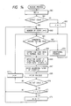
- Figs. 7A and 7B are flow charts of image recording processing for one page in the facsimile apparatus of this embodiment.
- the control program for executing this processing is stored in the ROM 114 of the control unit 101.
- step S1 recording data for one line is serially output to the shift register 130.
- step S2 Upon completion of, transportation of one-line recording data, the latch signal 44 is output in step S2, so that the one-line recording data is stored in the latch circuit 131.
- step S3 the number of steps of the motor 25 is calculated on the basis of the rotating amount of the disc 34, and the ink sheet 14 is conveyed by a (1/n) line of the recording paper 11 in the direction of the arrow a in Fig. 2. The conveying processing of the ink sheet 14 will be described later with reference to the flow chart of Fig. 7B.
- step S4 the motor 24 is driven to convey the recording paper 11 by one line in the direction of the arrow b.
- the one-iine length corresponds to a length of one dot recorded by the thermal head 13.
- step S5 blocks of the heat generating elements 132 of the thermal head 13 are energized. It is checked in step S6 if all the m blocks are energized. If YES in step S6, i.e., if it is determined that all the blocks of the heat generating elements 13 are energized and one-line image recording is completed, the flow advances to step S7 to check if one-page image recording is completed. If NO in step S7, i.e., if it is determined that one-page image recording is not completed, the flow advances to step S8, and recording data for the next line is transported to the thermal head 13. The flow then returns to step S2.
- step S7 i.e., if it is determined that one-page image recording is completed, the flow advances to step S9, and the recording paper 11 is conveyed by a predetermined amount in the direction of the exhaust rollers 16a and 16b.
- step S10 the cutters 15a and 15b are driven to be meshed, so that the recording paper 11 is cut into a page.
- step S11 the cut recording paper 11 is exhausted by the exhaust rollers 16a and 16b to the outside of the apparatus.
- step S12 the remaining recording paper 11 is returned by a distance corresponding to an interval between the thermal head 13 and the cutters 15a and 15b, thus completing one-page recording processing.
- the conveyance drive operation of the motor 25 is preferably performed prior to that of the motor 24. Even if the motor 25 is driven, a delay time is caused by characteristics of the motor or the characteristics of the drive transmission system until the conveying operation of the ink sheet 14 is actually started. If the motor 24 is driven first, the same effect can be obtained. However, if a time interval between the beginning of the conveying operation of the recording paper 11 and the beginning of the drive operation of the thermal head 13 (recording operation in step S4) becomes too much, a gap may be undesirably formed between recorded dots.
- the ink sheet 14 may be conveyed at the speed Vp/n in the direction opposite to the recording paper 11 when the recording paper 11 is conveyed, or may be conveyed with an increased n value. Furthermore, the ink sheet may be conveyed in the same manner as in the recording paper 11 or may be stopped in position.
- Fig. 7B is a flow chart showing ink sheet conveying processing in step S3 of Fig. 7A.
- step S20 It is checked in step S20 if the sensor 35 is ON. If NO in step S20, the flow advances to step S21 to check if the sensor 36 is ON. If both the sensors 35 and 36 are OFF, this indicates that the rotational angle R falls within the range of 0 to 60 (Fig. 6A), and the flow advances to step S22.
- step S22 the number of drive steps of the motor 25 with respect to a one-line conveying operation of the recording paper 11 is set to be "6".
- step S21 i.e., it is determined that the sensor 36 is ON, this indicates that the rotational angle R exceeds 300°, as shown in Fig. 6D, the number of drive steps of the motor 25 is set to be "3".
- step S20 i.e., if it is determined that the sensor 35 is ON, the flow advances to step S23 to check if the sensor 36 is ON. If NO in step S23, since the rotational angle R falls within the range of 60° to 150°, the flow advances to step S24, and the number of drive steps of the motor 25 is set to be "5". On the other hand, if it is determined in step S23 that the sensor 36 is ON, since the rotational angle falls within the range of 150° to 300°, as shown in Figs. 6C and 6D, the flow advances to step S25, and the number of steps of the motor 25 is set to be "4".
- step S27 the flow advances to step S27 to detect the presence/absence of the ink sheet 14 by the ink sheet sensor 19. If the ink sheet 14 is absent, the flow advances to step S28, and the indicating unit 104 is caused to indicate the absence of the ink sheet. However, if the ink sheet 14 is present, the flow advances to step S29, the motor 25 is rotated by the number of steps set in step S22 or in one of steps S24 to S26 to convey the ink sheet 14 by a 1/n line with respect to the one-line conveying operation of the recording paper 11.
- the ink sheet can be conveyed with the almost constant n value regardless of a change in diameter of the ink sheet take-up roller 18.
- Fig. 8 is a perspective view showing an arrangement of a conveying mechanism system of recording paper and an ink sheet according to a second embodiment.
- the same reference numerals in the second embodiment denote the same parts as in the first embodiment.
- an encode disc 61 having slits is arranged at a rotating shaft of a supply roller 17 for an ink sheet 14, and its rotation is detected by a photointerrupter 62 to detect rotation of the supply roller 17.
- a photointerrupter 62 to detect rotation of the supply roller 17.
- S is the number of drive steps of a motor 25 for conveying the ink sheet, which is required for conveying the ink sheet 14 by a 1/N line.
- the ink sheet 14 is fed from the supply roller 17, and is taken up by the take-up roller 18.
- the take-up roller 18 is driven by the motor 25.
- the number of steps of the motor 25 necessary for rotating the encode disc 61 byes e.g., 30°
- the motor 25 is driven by five steps with respect to the one-line conveying operation of the recording paper, thus conveying the ink sheet 14.
- the number s of drive steps of the motor 25 with respect to one line of the recording paper 11 is set to be "4".
- the number s of drive steps of the motor 25 with respect to one line of the recording paper 11 is set to be "3".
- Figs. 10A and 10B are flow charts showing a recording operation of the second embodiment. This operation is continuously executed from when the ink sheet 14 is loaded until all the ink sheet is fed from the ink sheet supply roller 17.
- step S30 the number S of steps of the motor 25 which is driven for one line of the recording paper 11 is set to be, e.g., "6".
- step S31 a counter allocated in a RAM 115 of a control unit 101 is cleared.
- step S32 an image for one line is recorded on the recording paper 11.
- the one-line image recording processing is shown in the flow chart of Fig. 10B. It is checked in step S33 if the slits 63 of the encode disc 61 are detected by the photosensor 62. Steps S32 and S33 are repeated until the slits 63 are detected.
- step S34 one-line image recording processing is executed. It is then checked if the slits 63 are completely passed.
- step S36 if passage of the slits 63 is detected, the flow advances to step S36, and one-line image recording processing is performed.
- step S37 S is added to the content of the counter. It is checked in step S38 if the slits 63 are detected. If NO in step S38, the flow advances to step S39 to check if the content of the counter is equal to or larger than a predetermined value. If NO in step S39, the flow returns to step S36; otherwise, the flow returns to step S31, and the above-mentioned operation is executed.
- step S40 the flow advances to step S40 to check if the count value of the counter is equal to or smaller than a predetermined value. If NO in step S40, the flow advances to step S41, and the counter is cleared. Thereafter, the flow returns to step S34. However, if YES in step S40, the flow advances to step S42, and the number S of steps is decremented by 1. In step S43, the counter is cleared, and processing is ended.
- Fig. 10B is a flow chart showing one-line recording processing in Fig. 10A.
- step S50 recording data for one line is transported to and latched by a thermal head 13 (steps S50 and S51).
- step S52 the motor 25 is driven by the number of steps indicated by S set in step S30 or S42 in Fig. 10A.
- step S53 the recording paper 11 is conveyed by one line.
- steps S54 and S55 heat generating resistors 132 of the thermal head 13 are energized in units of blocks to perform image recording.
- step S56 it is checked if an image recording operation for one page is completed. If NO in step S56, the flow returns to the main routine. However, if YES in step S56, the flow advances to step S57, and the recording paper 11 is conveyed by a predetermined amount.
- step S58 the recording paper 11 is cut by cutters 15a and 15b, and the cut recorded paper 11 is exhausted outside the apparatus.
- step S59 the start portion of the recording paper 11 is returned to the recording position of the thermal head 13 in step S59, thus completing one-line image recording processing.
- the ink sheet 14 may be stopped in position or may be conveyed together with the recording paper 11 as described in the flow chart of Fig. 7B.
- the movement of the ink sheet 14 in this case is not particularly limited.
- the number of steps of the motor 25 required for rotating the ink sheet supply roller 17 by a predetermined angle is obtained.
- the number of steps becomes equal to or smaller than, e.g., 4035, 2918, or 1575
- the number of steps for driving the motor 25 is changed from 6 to 5, from 5 to 4, or from 4 to 3.
- a variation in feed amount of the ink sheet 14 caused by changes in diameters of the ink sheet take-up roller 18 and the supply roller 17 can be minimized. Since control can be made to uniform the feed amount of the ink sheet 14 with respect to the predetermined feed amount of the recording paper 11, an image can always be recorded at a uniform recording density, and the ink sheet 14 can be efficiently used.
- the number S of steps is set to be an initial value, e.g., "6", and the counter is cleared to "0".
- Fig. 11 shows an arrangement of a conveying mechanism of recording paper and an ink sheet according to a third embodiment, and the same reference numerals in the third embodiment denote the same parts as in the above embodiments.
- Scales 72 are printed at given intervals t over the total length of an ink sheet 14A on a surface, i.e., a lower surface (upper surface in Fig. 11) opposite to an ink-coated surface of the ink sheet 14A.
- the interval t is sufficiently shorter than the length of A5-sized standard paper, and the scales 72 are read by a photosensor 71.
- the apparatus shown in Fig. 11 includes a driver circuit 83 for driving a motor 24 for conveying recording paper, a driver circuit 75 for exciting a phase A of a motor 25 for conveying an ink sheet, and a driver circuit 76 for exciting a phase B of the motor 25. D/A converters 77 and 78 respectively .
- control unit 101 a receive control signals 79 and 81 from a control unit 101 a to change drive voltages of the corresponding driver circuits, thus microstep-controlling the motor 25.
- the control unit 101 a outputs phase excitation signals 80 and 82 for the phases A and B of the motor 25.
- the driver circuits 75 and 76 output signals 73 and 74 for exciting the phases A and B of the motor 25.
- Fig. 12A shows an excitation vector of a two-phase/four-pole stepping motor as the motor 24 or 25.
- Fig. 12B shows the phase excitation order when this -motor is driven by 1-2 phase excitation.
- Fig. 12B shows an opposite phase of each phase.
- the motor 24 is driven by 1-2 phase excitation shown in Fig. 12B, so that the recording paper 11 is conveyed by one line in response to one excitation pulse.
- Fig. 13A shows microstep control used in the drive operation of the motor 25.
- the phase A is obtained upon excitation by a current corresponding to cose
- the phase B is obtained upon excitation by a current corresponding to sine.
- Fig. 13B shows a table of 256 stages in this case.
- control is made to convey the ink sheet 14A by a (1/n) line with respect to a one-line conveying operation of the recording paper, and an initial value of n at the beginning of use of the ink sheet 14A is set to be "5".
- the core diameter of the take-up roller 18 is increased. Even if the take-up roller is rotated by the same amount, the conveying distance of the ink sheet 14A is gradually prolonged, and the n value is gradually decreased. For this reason, processing for restoring n to 5 is required as in the above embodiments. In this embodiment, this processing is performed three times for one roll of the ink sheet.
- Control of the motor 25 is made such that 256 stages per revolution are selected while skipping m stages (m is an integer sufficiently larger than the number of control times for restoring n to a predetermined value).
- the moving amount of the ink sheet 14A is obtained by detecting the scales 72 by the reflection type photosensor 71.
- the photosensor 71 is turned on when it detects the scale 72, and is turned off when the motor 25 is driven by one step.
- the number J of steps for driving the motor 25 is counted from a given scale until the next scale is detected. When the number J becomes smaller than a predetermined value, correction control is performed.
- the diameter of the take-up roller 18 is increased.
- the conveyance amount of the ink sheet 14A by single excitation operation of the motor 25 is increased.
- Such an increase appears as a decrease in the number J of steps for conveying the ink sheet 14A by a length corresponding to an interval between adjacent scales. Therefore, when the J value becomes smaller than a predetermined value K (e.g., 80 steps), the m value is decremented by one to decrease the minimum step angle of the motor 25.
- K e.g. 80 steps
- the J value is increased to be approximate to an initial value (e.g., 100), and the n value is restored to a value near "5". In this manner, n can be maintained in a predetermined range.
- Fig. 14 is a flow chart showing image recording processing of the third embodiment.
- a control program for executing this control is stored in a ROM 114a of the control unit 101 a.
- step S60 the number m of skipped steps is set to be a maximum value.
- This setup operation is performed by outputting predetermined digital values as the control signals 79 and 81 to the D/A converters 77 and 78 and outputting appropriate control voltages from the D/A converters 77 and 78 to the driver circuits 75 and 76. It is checked in step S61 if the scale 72 is detected. If YES in step S61, the flow advances to step S62, and the number J of steps is set to be "0". However, if NO in step S61, the flow advances to step S63, and the K value is set in J. Thereafter, the flow advances to step S64.
- step S64 It is checked in step S64 if image recording processing for one page is completed. If NO in step S64, the flow advances to step S65, and recording data for one line is transported to the thermal head 13.
- step S66 the excitation signals 80 and 82 are output to excite the motor 25 by n steps while skipping m steps.
- step S67 the motor 24 is excited by one step to convey the recording paper 11 by one line.
- step S68 the thermal head 13 is energized in units of blocks to perform image recording for one line.
- step S73 additional processing such as cutting, exhausting, and the like of recording paper is performed,
- the m value (output voltage of the D/A converter) is set to be an initial maximum value when the ink sheet 14A is exchanged. The m value will not be restored to an initial value unless the ink sheet 14A is exchanged.
- the J value is also preset to the K value upon exchange of the ink sheet 14A.
- scales are printed on the lower surface of the ink sheet 14A, and are detected by the photosensor.
- the present invention is not limited to this.
- the scales may be formed by grooves, and the grooves may be detected by a photointerrupter, a microswitch, or the like.
- the motors 25 and 24 comprise the two-phaseifour-pole stepping motors.
- the motors may comprise DC motors or servo motors.
- the n value is controlled to be equal to or smaller than the predetermined value.
- the n value may be controlled to fall within the range of n ⁇ a (n » a) having n as the central value.
- the number of steps or the step angle of the motor 25 is changed regardless of divisions of pages.
- the number of steps or step angle may be changed after the image recording of the given page is completed. An image on the given page can be recorded at an almost uniform image density.
- the number of drive steps of the motor 25 for conveying the ink sheet is decreased to change the conveyance amount of the ink sheet 14 (14A).
- the step angle of the motor 25 may be decreased by microstep driving like in the third embodiment.
- Fig. 15 shows an image recording state when an image is recorded while the recording paper 11 and the ink sheet 14 (14A) are conveyed in opposite directions.
- the recording paper 11 and the ink sheet 14 (14A) are clamped between the platen roller 12 and the thermal head 13, and the thermal head 13 is pressed against the platen roller 12 by the springs 21 at a predetermined pressure.
- the recording paper 11 is conveyed at a speed Vp in a direction of an arrow b upon rotation of the platen roller 12.
- the ink sheet 14 (14A) is conveyed at a speed V, in a direction of an arrow a upon rotation of the motor 25 for conveying the ink sheet.
- the ink sheet 14 (14A) is constituted by a base film 14a and an ink layer 14b.
- a portion 92 of an ink of the ink layer portion 91 heated upon energization of the heat generating resistors 132 is transferred onto the recording paper 11.
- the transferred ink layer portion 92 corresponds to almost 1/n of the thickness of the ink layer.
- a shearing force with respect to an ink must be generated at a boundary 93 of the ink layer 14b to transfer only the portion 92 onto the recording paper 11.
- this shearing force varies depending on the temperature of the ink layer. As the temperature of the ink layer is higher, the shearing force tends to be decreased.
- the heating time of the ink sheet 14 (14A) is shortened, the shearing force in the ink layer is increased. Therefore, if a relative speed between the ink sheet 14 (14A) and the recording paper 11 is increased, an ink layer portion to be transferred can be reliably peeled from the ink sheet 14 (14A).
- the heating time of the thermal head 13 in the facsimile apparatus is as short as about 0.6 ms, the ink sheet 14 (14A) and the recording paper 11 are conveyed in the opposite directions to increase the relative speed between the ink sheet 14 (14A) and the recording paper 11.
- Fig. 16 is a sectional view of the ink sheet used in a multi-print mode of this embodiment (including embodiments to be described later).
- the ink sheet has a four-layered structure.
- a second layer is a base film as a support member of the ink sheet 14 (14A, 14B).
- an aromatic polyamide film or capacitor paper having a high heat resistance are advantageously used.
- a conventional polyester film can be satisfactorily used.
- the thickness of this layer is decreased as much as possible in favor of printing quality since it serves as a medium.
- the thickness preferably falls within the range of 3 to 8 um in terms of a mechanical strength.
- a third layer is an ink layer containing an ink capable of performing n transfer operations to the recording paper 11 (recording sheet).
- the ink layer contains the following components. That is, a resin such as EVA as an adhesive, carbon black or Nigrosine dye for coloring, a carnauba wax or paraffin wax as a binding material, and the like are mixed as major components to withstand n times of use at a given portion.
- a coating amount of this mixture preferably falls within the range of 4 to 891m2, A sensitivity or density can vary depending on the coating amount, and the coating amount can be desirably selected.
- a fourth layer is a top coating layer for preventing an ink in the third layer from being transferred under pressure onto recording paper at a non-printing portion.
- the top coating layer contains a transparent wax, and the like. Thus, only the fourth layer is transferred under pressure, and background contamination of the recording paper can be prevented.
- a first layer is a heat-resistant coating layer for protecting the base film as the second layer from heat of the thermal head 13. This layer is suitable for the multi-print mode in which a heat energy for n lines may be repeatedly applied to a given portion (when black data continues). However, it can be selected that this layer may or may not be used. This layer is effective for a base film having a relatively low heat resistance such as a polyester film.
- the ink sheet 14 may comprise a base layer and a porous ink holding layer arranged on one surface of the base layer and containing an ink.
- a heat-resistant ink layer having a microporous net structure may be formed on a base film, and may contain an ink.
- the example of the material of the base film includes paper or a film consisting of polyimide, polyethylene, polyester, polyvinyl chloride, triacetyl cellulose, nylon, or the like.
- the heat-resistant coating layer need not always be arranged.
- the example of the material of this layer includes a silicone resin, an epoxy resin, a fluoroplastic, ethrocellulose, or the like.
- An example of an ink sheet having a heat-sublimate ink includes an ink sheet in which a color material layer containing spacer particles formed of a guanamine resin and a fluoroplastic and a dye is formed on a base formed of a polyethylene telephthalate, polyethylene naphthalate, or aromatic polyamide film.
- rotation of the ink sheet take-up roller 18 is controlled to obtain an almost uniform conveyance amount of the ink sheet 14 with respect to the predetermined conveyance amount of the recording paper 11. Therefore, conveyance control of the ink sheet 14 by the capstan roller and the pinch roller can be omitted, and the mechanism portion of the printer can be simplified.
- the conveyance amount of the ink sheet with respect to the predetermined conveyance amount of the recording paper 11 can be kept almost constant.
- An embodiment to be described below provides a thermal transfer recording apparatus which detects a conveyance amount of an ink sheet corresponding to a predetermined conveyance drive amount of an ink sheet, and when the conveyance amount is different from the drive amount, adjusts the conveyance drive amount of the ink sheet to maintain a constant conveyance amount of the ink sheet, and a facsimile apparatus using the recording apparatus.
- the same reference numerals denote the same parts as the above embodiments, and a detailed description thereof will be omitted.
- Fig. 17 is a side sectional view of a facsimile apparatus to which the embodiment of the present invention is applied.
- a photosensor 71 (to be described later) reads stripes printed on an ink sheet 14B to detect a conveying length of the ink sheet 14B.
- Fig. 18 shows in detail a conveying system of recording paper 11 and the ink sheet 14B in a recording unit.
- a thermal head 13 comprises a line head.
- the thermal head 13 receives serial recording data for one line and a latch signal from a signal line 43, and drives heat generating elements consisting of heat generating resistors 132 in units of a plurality of blocks to perform recording for one line.
- a driving circuit 46 receives a drive signal for the thermal head 13, and outputs a strobe signal 44 for driving the thermal head 13 in units of blocks.
- the photosensor 71 detects stripes 72 printed at predetermined intervals t on a surface (lower surface) opposite to an ink-coated surface of the ink sheet 14B to detect the conveyance amount of the ink sheet 14B.
- D/A converters 77 and 78 receive digital data from a control unit 101, perform digital-to-analog conversion of the digital data, and output analog data to driver circuits 75 and 76, respectively.
- a motor 124 for conveying recording paper comprises a stepping motor.
- a motor 125 for conveying an ink sheet comprises a two-phase/bipolar stepping motor for driving a take-up roller 18 for the ink sheet 148.
- a driver circuit 75 excites a phase A of the motor 125
- a driver circuit 76 excites a phase B of the motor 125.
- These driver circuits 75 and 76 receive reference voltage signals from the corresponding D/A converters 77 and 78, and supply currents corresponding to the input voltages to the corresponding phases of the motor 125 to rotate the motor 125 in a microstep driving mode.
- a driver circuit 83 drives the motor 124.
- Transmission gears 26 and 27 transmit rotation of the motor 124 to a platen roller 12, and transmission gears 28 and 29 transmit rotation of the motor 125 to the take-up roller 18.
- the motors 124 and 125 comprise stepping motors in this embodiment.
- these motors may comprise, e.g., DC motors.
- Fig. 19 shows the concept of a two-phase/four-pole stepping motor.
- phase excitation mode When a stepping motor is rotated at a small angle, e.g., in a 1-2 phase excitation mode (half-step control), phases are excited in the order of A - AB - B - BAX - AXBX ⁇ BXA - A.... In this case, X indicates an opposite phase.
- the stop positions of a rotor 300 are limited, and rotation control with a further smaller step angle is difficult to achieve.
- Fig. 20 is a view for explaining the principle of a microstep driving mode capable of rotating a stepping motor at a further smaller angle.
- a rotor When a current corresponding to icose is supplied to a phase A and a current corresponding to isine is supplied to a phase B, a rotor can be stopped at an arbitrary angle 0, as shown in Fig. 20.
- one cycle (360°) from initial excitation of the phase A until the next excitation of the phase A is divided into 256 stages, and a table representing current values of the phases A and B (digital values to be output to the D/A converters 77 and 78) used when the motor is stopped at stop positions corresponding to the stages is created.
- Fig. 21 shows this table.
- the rotor 300 is rotated by (360/256) x 2°.
- the stop position of the rotor 300 can be controlled in units of (360/256) * .
- the table shown in Fig. 21 is created, and current values are sequentially indicated by a pointer P to convey the ink sheet 14B.
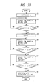
- Fig. 22 is a flow chart showing an initialization routine for determining the m value in the facsimile apparatus of this embodiment.
- a control program for executing this program is stored in a ROM 114. This processing is started when a power switch of the apparatus is turned on or when an ink sheet sensor 20 detects loading of the ink sheet 14B.
- step S1 an initial value of m as a skip value indicating the number of skipped current values shown in Fig. 21 is set to be, e.g., "127".
- the gear ratio of the transmission gears 28 and 29 are set so that a conveying speed of the ink sheet 14B reaches a predetermined value upon excitation of the motor 125.
- step S2 the motor 125 is rotated based on the m value set in step S1 to convey the ink sheet 14B by one line in a subscan direction (a direction). It is then checked in step S3 if the photosensor 71 detects the stripe 72. Steps S2 and S3 are repetitively executed until the photosensor 71 detects the stripe. This operation is performed to detect the first stripe of the ink sheet 14B. When the stripe is detected, the flow advances to step S4, and a counter CNT of a RAM 115 is set to be "0".
- step S1 When a new ink sheet 14B is loaded, this processing can be performed. However, when a used ink sheet 14B is loaded, it is checked after step S1 if the photosensor 71 detects the stripe. If no stripe is detected, processing from step S2 is executed. When the photosensor 71 is located immediately above the stripe and detects the stripe, the ink sheet 14B is conveyed until the photosensor 71 does not detect the stripe. Thereafter, the flow may advance to step S2.
- step S5 the ink sheet 14B is conveyed by one line in the same manner as in step S2, and the counter CNT is incremented by one. It is checked in step S6 if the stripe detected in step S3 is passed. If YES in step S6, the flow advances to step S7.
- step S7 the ink sheet 14B is conveyed by one line in the same manner as in step S5, and the counter CNT is incremented by one each time. It is checked in step S8 if the photosensor 71 is ON (the next stripe is detected). Steps S7 and S8 are repetitively executed until the stripe is detected.
- the counter CNT counts the number of excitation steps for driving the motor 125 from when the end portion of the first stripe is detected until the end portion of the next stripe is detected.
- the flow advances to step S9, and the m value is determined on the basis of the content of the counter CNT.
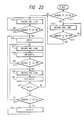
- Fig. 23 is a flow chart showing m changing processing during image recording processing in the facsimile apparatus of this embodiment.
- a control program for executing this processing is stored in the ROM 114. This processing is executed simultaneously with image recording upon reception of a facsimile image or a copying operation.
- step S11 It is checked in step S11 if the photosensor 71 detects the stripe. If NO in step S11, the flow advances to step S14. If the photosensor 71 is ON, image recording for one line is performed in step S12, and steps S12 and S13 are executed until the photosensor 71 does not detect the stripe in step S13. When the photosensor 71 does not detect the stripe, the flow advances to step S14. With this processing, since the start position of image recording on the ink sheet 14B is indefinite, the count value of the counter CNT is caused to correspond to the interval between the adjacent stripes.
- step S14 image recording processing for one line is executed. It is then checked in step S15 if the photosensor 71 detects the stripe. Steps S14 and S15 are repetitively executed until the stripe is detected. When the first stripe is detected, the flow advances to step S16, and the counter CNT is set to be "0". In steps S17 to S19, image recording is performed until the stripe cannot be detected. The counter CNT is incremented by one every image recording for one line.
- step S20 image recording for the next line is performed, and in step S21, the counter CNT is incremented by one.
- step S22 the value C s of the counter CNT is compared with S. If C s z S, the flow returns to step S14. However, if C s ⁇ S, the flow advances to step S23 to check if the photosensor 71 detects the stripe 72. If the photosensor 71 detects the stripe, the flow advances to step S24, and m is decremented by one. The flow then returns to step S16.
- the photosensor 71 detects the stripe 72 before the value of the counter CNT reaches the predetermined value S (the ink sheet 14 is conveyed by a length ( t + ⁇ t); where ⁇ l is the line width of each stripe), if the motor 125 is driven by one line, the length of the ink sheet 14B actually conveyed exceeds one line. For this reason, the skip value m when the table shown in Fig. 21 is referred is decreased to decrease the step angle of the motor 125, thereby adjusting the conveyance amount of the ink sheet 14B.
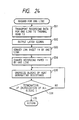
- Fig. 24 is a flow chart showing one-line recording processing in steps S12, S14, S17, and S20 in Fig. 23.
- step S31 When one-line image data is prepared, it is transported to the thermal head 13 in step S31, and is latched in the thermal head in response to a latch signal in step S32.
- step S33 the motor 125 is excited to convey the ink sheet 14B by one line.
- the current values of the phases A and B of the motor 125 are determined with reference to the current values indicated by the pointer P and its skip value m of the table shown in Fig. 21.
- Values a; and b for indicating current values of the phases A and B indicated by the pointer P and m are output to the corresponding D/A converters 77 and 78.
- the motor 125 is rotated at a designated step angle.
- step S34 the motor 124 is rotated to convey the recording paper by one line.
- step S35 one block of the heat generating resistors 132 is energized. It is checked in step S36 if all the blocks are energized (one-line image recording is completed). If YES in step S36, the flow returns to the main routine.
- a rotary disc 61 formed with radial slits for detecting a rotational angle of an ink sheet supply roller 17, and a photointerrupter 62 for detecting light passing through the slit are arranged.
- the initial value of m is set to be "127" after a new ink sheet is loaded or a power switch is turned on to convey the ink sheet 14 as in the embodiment (Fig. 18).
- Image recording processing in this case will be described below.
- the image recording processing is substantially the same as the flow chart of the embodiment shown in Fig. 23.
- the slits of the rotary disc 61 are detected by the photointerrupter 62 in place of detecting the stripes by the photosensor 71, and the count value of the counter CNT between adjacent slits is compared with S.
- the S value to be compared with the count value of the counter CNT in step S21 is always constant.
- the diameter of the take-up roller 18 is increased.
- the number of steps for the motor 125 for conveying the ink sheet 14 is decreased as the used amount of the ink sheet is increased.
- the diameter of the ink sheet supply roller 17 is decreased as the used amount of the ink sheet 14 is increased. Therefore, the number of excitation steps of the motor 125 driven between adjacent slits of the disc 61 is decreased.
- step S24 m is decremented by one, and the S value is calculated in correspondence with the m value.
- the count value C s of the counter CNT and S are compared on the basis of the S value changed in step S22, so that the conveying speed of the ink sheet 14 can be kept almost constant regardless of changes in diameters of the rollers 18 and 17.
- the ink sheet 14 is conveyed by one line to perform recording while the recording paper 11 is conveyed by one line.
- the embodiment and the modification can be applied to recording using a so-called multi-print sheet capable of performing a plurality of times of image recording operations.
- a conveying length of an ink sheet conveyed after completion of each image recording operation or during image recording is set to be smaller than the recording length L (L'n : n > 1) to perform image recording.
- the multi-print operation will be described below.
- the m value is initialized to, e.g., "30" in step S1.
- step S2 the ink sheet 14 is conveyed by a 1/n line.
- steps S2 and S3 it is checked if the photosensor 71 is turned on to detect a stripe. If the stripe is detected the flow advances to step S4, and the counter CNT is set to be "0".
- the initial value of m is determined on the basis of the value of the counter CNT corresponding to an interval between adjacent stripes in substantially the same manner as in the embodiment shown in Fig. 18, except that the ink sheet 14 is conveyed by a 1/n line in steps S5 and S7.
- the m value is changed during the recording operation.
- the ink sheet 14 is conveyed by a 1/n line (step S33 in Fig. 24) in one-line image recording processing.
- the conveyance amount of the ink sheet corresponding to the conveyance drive amount of the ink sheet is detected.
- the conveyance drive amount of the ink sheet is adjusted to keep the conveyance amount of the ink sheet constant.
- An embodiment to be described below provides a thermal transfer recording apparatus which can detect and control a rotating amount of a supply roller with respect to a drive amount of a take-up roller, and can record a high-quality image, and a facsimile apparatus using the recording apparatus.
- the embodiment to be described below provides a thermal transfer recording apparatus which detects a rotating amount of a supply roller with respect to a drive amount of a take-up roller, and obtains a conveying length of an ink sheet on the basis of these drive amount and rotating amount to change the conveyance amount of the ink sheet, thus controlling the conveyance amount of the ink sheet, and a facsimile apparatus using the recording apparatus.
- a drive amount of the take-up roller corresponding to a predetermined rotating amount of the supply roller is detected.
- this drive amount is equal to or smaller than a predetermined value, the drive amount of the take-up roller is changed.
- the conveying length of the ink sheet with respect to a predetermined rotating amount of the supply roller is calculated, and when the conveying length exceeds a predetermined value, the conveyance amount of the ink sheet is changed.
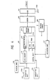
- Fig. 25 shows electrical connections between a control unit 101 and a recording unit 102 in the facsimile apparatus of this embodiment.
- Fig. 26 shows an arrangement of the facsimile apparatus of this embodiment.
- a difference from the arrangement shown in Fig. 1 is that the photosensors 35 and 36 are omitted in this embodiment, and a photointerrupter 62 for detecting a rotating amount of an ink sheet supply roller 17 is arranged.
- a difference between Figs: 26 and 3A is that the sensor 23 for detecting the take-up diameter of the ink sheet 14 is omitted from this embodiment. Therefore, the description associated with Figs. 1 and 3A will be quoted for other arrangements.
- a minimum recordable paper size is an A5 size, and is determined as a minimum recording size since recording is performed using a longitudinal direction of this paper as the main scan direction.
- the length in a subscan direction in this case is about 148 mm.
- recording paper 11 is conveyed by (1/15.4) mm when a motor 24 for conveying recording paper is driven by one step.
- the core diameter of an ink sheet supply roller 17 is represented by r o and a roller diameter when all the ink sheet 14 is wound around the supply roller 17 is represented.by r 1 .
- the diameter r 1 is given by: where t is the thickness of the ink sheet 14, and L is the total length of the ink sheet 14.
- an actual recording length is set to be equal to or smaller than (148/2) mm.
- the slit 63 is detected at least twice by the photointerrupter 62. If a ratio n of the conveying length of the ink sheet 14 to the one-line conveying length of the recording paper 11 is 5, when the supply roller 17 is rotated by the angle ⁇ s , the conveying length of the ink sheet 14 is ⁇ 148/(2 x 5) ⁇ mm or less.
- the slits can be provided at smaller angular intervals than ⁇ s .
- n indicates the ratio of the conveying length of the ink sheet 14 to the one-line conveying length of the recording paper 11, as described above.
- S indicates the number of steps of the motor 25 required for conveying the ink sheet 14 by a 1/n line.
- the ink sheet 14 is fed from the supply roller 17, and is taken up by the take-up roller 18.
- the take-up roller 18 is driven by the motor 25.
- the step count of the motor 25 necessary for rotating the encode disc 61 by ⁇ s e.g., 30° ( 1 (/6)) by rotating the take-up roller 18 is checked, and when this value becomes equal to or smaller than "4035", the motor 25 is driven by five steps with respect to the one-line conveying operation of the recording paper, thus conveying the ink sheet 14.
- the number S of drive steps of the motor 25 with respect to one line of the recording paper is set to be "4".
- the number S drive steps of the motor 25 with respect to one line of the recording paper 11 is set to be "3".
- Fig. 27 is flow chart showing a recording operation of this embodiment. This operation is continuously executed from when the ink sheet 14 is loaded until all the ink sheet is fed from the ink sheet supply roller 17 and runs out.
- step S1 the number S of steps of the motor 25 which is driven for one line of the recording paper 11 is set to be, e.g., "6".
- step S2 a counter allocated in a RAM 115 of a control unit 101 is cleared.
- step S3 an image for one line is recorded on the recording paper 11. Note that the one-line image recording processing is shown in the flow chart of Fig. 10B. It is checked in step S4 if the slit 63 of the encode plate 61 is detected by the photosensor 62. Steps S3 and S4 are repeated until the slit 63 is detected.
- step S5 one-line image recording processing is executed. It is then checked in step S6 if the slit 63 detected in step S4 is completely passed.
- step S7 the flow advances to step S7, and one-line image recording processing is performed.
- step S9 If the slit 63 is detected in step S9, the flow advances to step S13, and one-page image recording is executed in steps S13 and S14. When one-page image recording is completed, the flow advances to step S15. In this case, since the value of the counter is equal to or smaller than the predetermined value, the number S of steps is decremented by one, and the flow returns to step S2 to execute the above-mentioned operation.
- the slit can be detected at least twice. Therefore, sensor data for correcting the number of drive steps of the motor 25 can be reliably detected.
- the number of steps of the motor 25 required for rotating the ink sheet supply roller 17 by a predetermined angle is obtained.
- the number of steps becomes equal to or smaller than, e.g., 4035, 2918, or 1575
- the number of steps for driving the motor 25 is changed from 6 to 5, from 5 to 4, or from 4 to 3.
- a variation in feed amount of the ink sheet 14 caused by changes in diameters of the ink sheet take-up roller 18 and the supply roller 17 can be minimized.
- control can be made to uniform the feed amount of the ink sheet 14 with respect to the predetermined feed amount of the recording paper, an image can always be recorded at a uniform recording density, and the ink sheet 14 can be efficiently used.
- the number S of steps is set to be an initial value, e.g., "6", and the counter is cleared to "0".
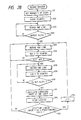
- Fig. 28 is a flow chart showing a modification of recording processing of this embodiment.
- Step S31 to S34 in Fig. 27 are the same as steps S1 to S4 in Fig. 27.
- step S35 the flow advances to step S35, and one-line recording processing is executed.
- step S36 the number s of steps is added to the content of the counter. In this manner, every time one-line recording processing is executed, the number of steps of the motor 25 for conveying the ink sheet 14 is added, and it is checked in step S40 if the slit 63 is detected again.
- step S41 the conveying length of the ink sheet 14 is calculated on the basis of the number of drive steps stored in this counter and the relative angle 0s of the slits 63.
- step S42 When the conveying length is calculated in this manner, the counter is cleared in step S42. It is then checked in step S43 if the conveying length calculated in step S41 is larger than a predetermined length. If NO in step S43, the flow returns to step S35 to execute the above-mentioned operation. However, if YES in step S43, i.e., if the conveying length calculated in step S41 is larger than the predetermined length, the flow advances to step S44, and the number s of steps is decremented by one. Thereafter, the flow returns to step S35.
- Scales 72 are printed at given intervals over the total length of an ink sheet 14A on a surface, i.e., a lower surface (upper surface in Fig. 11) opposite to an ink-coated surface of the ink sheet 14A.
- the interval t is sufficiently shorter than the length of A5-sized standard paper (t ⁇ (w/2n); w is the subscan length (i.e., sheet width) of smallest-sized data), and the scales 72 are read by a photosensor 71.
- the apparatus shown in Fig. 11 includes the driver circuit 83 for driving the motor 24 for conveying recording paper, the driver circuit 75 for exciting the phase A of the motor 25 for conveying an ink sheet, and the driver circuit 76 for exciting the phase B of the motor 25.
- the D/A converters 77 and 78 respectively receive the control signals 79 and 81 from the control unit 101a a to change drive voltages of the corresponding driver circuits, thus microstep controlling the motor 25'
- the control unit 101a a outputs the phase excitation signals 80 and 82 for the phases A and B of the motor 25.
- the driver circuits 75 and 76 output signals 73 and 74 for exciting the phases A and B of the motor 25.
- the moving amount of the ink sheet 14A is obtained by detecting the scales 72 by the reflection type photosensor 71.
- the photosensor 71 is turned on when it detects the scale 72, and is turned off when the motor 25 is driven by one step.
- the number J of steps of driving the motor 25 is counted from a given scale until the next scale is detected. When the number J becomes smaller than a predetermined value, correction control is performed to decrease the drive step angle of the motor 25.
- the number of steps is changed to keep almost constant n.
- the step angle of the motor may be decreased.
- the number of drive steps or step angle of the motor 25 is performed regardless of divisions of pages.
- the number of drive steps or step angle may be changed after completion of the image recording of the given page.
- rotation of the support shaft of the ink sheet take-up roller 18 is controlled to almost uniform a conveyance amount of the ink sheet 14 with respect to the predetermined conveyance amount of the recording paper 11. Therefore, conveyance control of the ink sheet 14 by a capstan roller and a pinch roller can be omitted, and the mechanism portion of the printer can be simplified.
- Fig. 4 is quoted as the block diagram showing the schematic arrangement of the facsimile apparatus of this embodiment
- Fig. 26 is quoted as the side sectional view showing a mechanism portion of the facsimile apparatus of this embodiment (however, the sensor 19 shown in Fig. 26 is omitted)
- Fig. 8 is quoted as the perspective view showing a conveying mechanism of recording paper and an ink sheet
- Fig. 9 is quoted as a schematic view of an encode disc
- Fig. 7A is quoted as the flow chart showing recording processing
- Fig. 11 is quoted as the view showing the arrangement of a conveying system of an ink sheet and recording paper.
- an ink sheet fed from a supply means for feeding an ink sheet is taken up by a take-up means.
- An amount of an ink sheet fed from the supply means is detected in correspondence with a drive amount of the take-up means.
- the remain of the ink sheet in the feeding means is detected.
- the recording unit 102 includes driver circuits 48, 49, and 135 for respectively driving a motor 24 for conveying recording paper, a motor 25 for conveying an ink sheet, and a motor 39 for exhausting paper.
- the motors 24, 25, and 39 comprise stepping motors.
- these motors may comprises, e.g., DC motors.
- the recording unit also includes a photointerrupter 62, a counter 116, and a driving circuit 136 for driving cutters 15 (15a and 15b).
- An ink sheet 14 is fed from an ink sheet supply roller 17, and is taken up by a take-up roller 18.
- the take-up roller 18 is driven by the motor 25.
- the take-up roller 18 is driven in a direction of an arrow, the supply roller 17 and an encode disc 61 are rotated in the direction of the arrow.
- slits 63 of the encode disc 61 are formed to define an angle e s , as shown in Fig. 9.
- the motor 25 drives the support shaft of the take-up roller 18, even if the motor 25 is driven by a given step, the rotational angle of the ink sheet supply roller 17 changes in correspondence with a change in diameter of each of the supply roller 17 and the take-up roller 18. Therefore, in this embodiment, this change is detected by the photointerrupter 62 to obtain a remain of the ink sheet 14. More specifically, the number of steps of the motor 25 necessary for rotating the encode disc 61 by ⁇ s is checked to obtain the remain of the ink sheet 14. The principle of this operation will be described below.
- each of the take-up roller 18 and the supply roller 17 of the ink sheet 14 is represented by r o
- the diameter of the supply roller 17 when a predetermined amount of ink sheet is wound around the take-up roller 18 is represented by r ;
- the diameter of the take-up roller 18 is represented by r a .
- the length of the ink sheet 14 wound around the ink sheet supply roller 17 is represented by x
- the total length of the ink sheet 14 is represented by L
- a rotational angle obtained when the diameter of the ink sheet take-up roller 18 is r a is represented by ⁇ 1 (this rotational angle is uniquely determined by the number of rotation steps of the motor 25), and a rotational angle of the supply roller 17 having the diameter r; in this case is represented by eo. Since the length of the ink sheet 14 fed from the ink sheet supply roller 17 is equal to that of the ink sheet 14 taken up by the take-up roller 18, the following relationship is established:
- One-page image recording processing in the facsimile apparatus of this embodiment is the same as that shown in Fig. 7A, and a description thereof is quoted here.
- step S3 in Fig. 7A the motor 25 is driven to convey the ink sheet 14.
- the ink sheet 14 is conveyed by a (1/n) line of the recording paper 11 in a direction of an arrow a in Fig. 8.
- the conveying processing of the ink sheet 14 will be described below with reference to a flow chart of Fig. 30.
- Fig. 30 is a flow chart showing ink sheet conveying processing in step S3 of Fig. 7A.
- step S21 the motor 25 is driven by one step.
- step S22 the counter 116 allocated in a RAM 115 is incremented by one in correspondence with the number of drive steps of the motor 25.
- the counter 116 has been reset to "0" upon initialization of this facsimile apparatus.
- the flow advances to step S23 to check if the photointerrupter 62 detects the slit 63 of the encode disc 61. If NO in step S23, the flow advances to step S24 to check if the motor 25 is driven by a predetermined number of steps. If YES in step S24, the flow returns to the main routine. However, if NO in step S24, the flow returns to step S21, and the motor is driven by one step.
- the predetermined number of steps is one necessary for conveying the ink sheet 14 by a (1/n) line in the multi-print mode, and is one necessary for conveying the ink sheet by one line in a printing mode using a one-time ink sheet.
- step S23 the flow advances to step S25, the remain of the ink sheet 14 is calculated using equation (4) described above on the basis of the count value of the counter 116.
- step S26 the remain of the ink sheet 14 is indicated on an indicating unit 104.
- the remain indication may be made such that a remain length of the ink sheet 14 is digitally displayed or may be indicated stepwise by, e.g., % or a ratio.
- Remain detection in step S25 may be made by referring to a table or the like storing remain data in correspondence with the number of steps (the count value of the counter 116) for driving the motor 25.
- step S27 When the remain (or used length) of the ink sheet 14 is obtained, the flow advances to step S27.
- the number of steps for determining the conveying length of the ink sheet 14 conveyed in correspondence with one line of the recording paper 11 during image recording is corrected based on this value in correspondence with the diameters of the ink sheet supply roller 17 and the take-up roller 18. In this manner, the number of drive steps of the motor 25 to be compared in step S24 is changed.
- step S28 the counter 116 of the RAM 115 is reset to "0".
- the flow then advances to step S24.
- the counter 116 is cleared when a signal indicating that the ink sheet 14 is exchanged is input from an exchange detecting unit 38 after the remain of the ink sheet 14 is small.
- the ink sheet 14 can be accurately conveyed by driving the support shaft of the ink sheet take-up roller 18, and its remain can be accurately detected.
- Fig. 11 shows an arrangement of a conveying mechanism of recording paper and an ink sheet according to still another embodiment of the present invention.
- Scales 72 are printed at given intervals l over the total length of an ink sheet 14A on a surface, i.e., a lower surface (upper surface in Fig. 11) opposite to an ink-coated surface of the ink sheet 14A.
- the interval 1 is sufficiently shorter than the length of A5-sized standard paper, and the scales 72 are read by a photosensor 71.
- the apparatus shown in Fig. 11 includes a driver circuit 83 for driving a motor 24 for conveying recording paper, a driver circuit 75 for exciting a phase A of the motor 25 for conveying an ink sheet, and a driver circuit 76 for exciting a phase B of the motor 25.
- D/A converters 77 and 78 respectively receive control signals 79 and 81 from a control unit 101 a to change drive voltages of the corresponding driver circuits, thus microstep controlling the motor 25.
- the control unit 101 a outputs phase excitation signals 80 and 82 for the phases A and B of the motor 25.
- the driver circuits 75 and 76 output signals 73 and 74 for exciting the phases A and B of the motor 25.
- the present diameter of the take-up roller 18 is represented by r a
- the core diameter of the take-up roller 18 is represented by r o
- the thickness of the ink sheet 14A is represented by t
- its total length is represented by L
- the remain x can be uniquely determined.
- This processing is performed in the same manner as in the flow chart shown in Fig. 30 by checking in step S23 in the flow chart of Fig. 6B if the photointerrupter 71 detects the scale 72.
- the motor 25 may be microstep-driven using the D/A converters 77 and 78 to decrease the minimum step angle of the motor 25.
- scales 72 are printed on the lower surface of the ink sheet 14A, and are detected by the photosensor 71.
- the present invention is not limited to this.
- the scales 72 may be formed by grooves, and the grooves may be detected by a photointerrupter, a microswitch, or the like.
- the motors 25 and 24 comprise the two-phase/four-pole stepping motors.
- the motors may comprise DC motors or servo motors.
- rotation of the ink sheet take-up roller 18 is controlled, and the remain of the ink sheet can be detected by a sensor for detecting a conveyance amount of the ink sheet.
- a sensor for detecting a remain of the ink sheet can be omitted.
- a heating system is not limited to a thermal head system using the thermal head.
- an electrothermosensitive system or a laser transfer system may be employed.
- a recording medium is not limited to recording paper.
- the recording medium may be a fabric, a plastic sheet, or the like as long as an ink can be transferred thereto.
- the structure of the ink sheet is not limited to the roll structure shown in the above embodiments.
- the ink sheet may be of a so-called ink sheet cassette type, which is incorporated in a detachable cassette and is attached/detached to/from the recording apparatus main body together with the cassette.
- the facsimile apparatuses have been exemplified.
- the present invention is not limited to this.
- the present invention is applicable to a wordprocessor, a typewriter, a copying machine, or the like.
- full-line type apparatuses have been exemplified.
- the present invention is not limited to this.
- the present invention may be applied to a so-called serial type apparatus in which a thermal head is reciprocally moved.
- thermo transfer recording method and a recording apparatus using the method with which consumption of an ink sheet is reduced and high-quality recording can be performed.
Landscapes
- Impression-Transfer Materials And Handling Thereof (AREA)
Applications Claiming Priority (8)
| Application Number | Priority Date | Filing Date | Title |
|---|---|---|---|
| JP236368/88 | 1988-09-22 | ||
| JP23636888A JPH0286479A (ja) | 1988-09-22 | 1988-09-22 | 熱転写記録装置 |
| JP24898088A JPH0298471A (ja) | 1988-10-04 | 1988-10-04 | 熱転写記録装置及び該装置を用いたフアクシミリ装置 |
| JP248980/88 | 1988-10-04 | ||
| JP270879/88 | 1988-10-28 | ||
| JP63270879A JP2845371B2 (ja) | 1988-10-28 | 1988-10-28 | 熱転写記録装置及び該装置を用いたフアクシミリ装置 |
| JP27748888A JPH02125776A (ja) | 1988-11-04 | 1988-11-04 | 熱転写記録装置及び該装置を用いたフアクシミリ装置 |
| JP277488/88 | 1988-11-04 |
Publications (3)
| Publication Number | Publication Date |
|---|---|
| EP0360280A2 true EP0360280A2 (fr) | 1990-03-28 |
| EP0360280A3 EP0360280A3 (en) | 1990-10-24 |
| EP0360280B1 EP0360280B1 (fr) | 1996-07-10 |
Family
ID=27477661
Family Applications (1)
| Application Number | Title | Priority Date | Filing Date |
|---|---|---|---|
| EP89117562A Expired - Lifetime EP0360280B1 (fr) | 1988-09-22 | 1989-09-22 | Méthode et dispositif d'enregistrement par transfert thermique |
Country Status (3)
| Country | Link |
|---|---|
| US (2) | US5497183A (fr) |
| EP (1) | EP0360280B1 (fr) |
| DE (1) | DE68926808T2 (fr) |
Cited By (1)
| Publication number | Priority date | Publication date | Assignee | Title |
|---|---|---|---|---|
| EP0910038A3 (fr) * | 1991-08-15 | 2001-04-11 | Datacard Corporation | Système modulaire de traitement de cartes |
Families Citing this family (17)
| Publication number | Priority date | Publication date | Assignee | Title |
|---|---|---|---|---|
| DE68926808T2 (de) * | 1988-09-22 | 1997-01-30 | Canon Kk | Aufzeichnungsverfahren und -vorrichtung mit Thermoübertragung |
| DE69030538T2 (de) * | 1989-07-19 | 1997-10-23 | Canon Kk | Mit Wärmeübertragung arbeitendes Aufzeichnungsgerät |
| JPH045074A (ja) * | 1990-04-24 | 1992-01-09 | Canon Inc | 記録装置 |
| US6169560B1 (en) | 1990-12-25 | 2001-01-02 | Canon Kabushiki Kaisha | Thermal transfer recording apparatus with ink sheet slackness removal |
| DE69227934T2 (de) * | 1991-02-18 | 1999-06-10 | Canon K.K., Tokio/Tokyo | Aufzeichnungsgerät und Faksimilegerät, in dem dieses Aufzeichnungsgerät angewendet wird |
| JP2823007B2 (ja) * | 1996-12-27 | 1998-11-11 | 日本電気株式会社 | 連続用紙記録装置及び連続用紙の給紙方法 |
| US6081271A (en) * | 1997-05-23 | 2000-06-27 | International Business Machines Corporation | Determining view point on objects automatically in three-dimensional workspace from other environmental objects in a three-dimensional workspace |
| KR20000070594A (ko) * | 1997-12-01 | 2000-11-25 | 요트.게.아. 롤페즈 | 용지 인쇄용 열전달 포일 및 포일 소비 감소를 위한 수단을 갖춘 팩시밀리 장치 |
| US6522724B2 (en) * | 1998-01-20 | 2003-02-18 | Siemens Information And Communication Networks, Inc. | Apparatus and method that allow telephone callers to leave longer messages |
| US6089768A (en) * | 1998-05-05 | 2000-07-18 | Printronix, Inc. | Print ribbon feeder and detection system |
| US6206589B1 (en) * | 1999-09-24 | 2001-03-27 | Fargo Electronics, Inc. | Printer ribbon compensation |
| US6742858B2 (en) * | 2002-02-06 | 2004-06-01 | Brady Worldwide, Inc. | Label printer-cutter with mutually exclusive printing and cutting operations |
| JP2007152603A (ja) * | 2005-12-01 | 2007-06-21 | Funai Electric Co Ltd | プリンタ装置 |
| JP5663924B2 (ja) * | 2010-03-31 | 2015-02-04 | 株式会社リコー | シート移送装置及び画像形成装置 |
| JP2014087965A (ja) | 2012-10-30 | 2014-05-15 | Seiko Epson Corp | 搬送装置及び記録装置 |
| CN112830310A (zh) | 2013-03-25 | 2021-05-25 | 株式会社汤山制作所 | 药剂分包装置、药剂分包纸余量判断方法和药剂分包纸卷筒 |
| US10318904B2 (en) | 2016-05-06 | 2019-06-11 | General Electric Company | Computing system to control the use of physical state attainment of assets to meet temporal performance criteria |
Family Cites Families (19)
| Publication number | Priority date | Publication date | Assignee | Title |
|---|---|---|---|---|
| US4265410A (en) * | 1978-12-28 | 1981-05-05 | Western Electric Company, Inc. | Machine for winding strip material |
| JPS5783471A (en) * | 1980-11-14 | 1982-05-25 | Canon Inc | Thermal copying printer |
| US4442460A (en) * | 1980-12-10 | 1984-04-10 | Fuji Xerox Co., Ltd. | Copying machine |
| JPS58201686A (ja) * | 1982-05-20 | 1983-11-24 | Ricoh Co Ltd | 熱転写式プリンタ |
| US4496117A (en) * | 1982-11-01 | 1985-01-29 | Canon Kabushiki Kaisha | Web transport device |
| JPS5995177A (ja) * | 1982-11-25 | 1984-06-01 | Nippon Telegr & Teleph Corp <Ntt> | 転写形感熱記録装置 |
| JPS609785A (ja) * | 1983-06-30 | 1985-01-18 | Toshiba Corp | 記録装置 |
| JPS6083864A (ja) * | 1983-10-17 | 1985-05-13 | Fuji Xerox Co Ltd | 多色記録装置 |
| JPS60157890A (ja) * | 1984-01-27 | 1985-08-19 | Toshiba Corp | 画像形成装置 |
| JPS60236779A (ja) * | 1984-05-10 | 1985-11-25 | Fuji Xerox Co Ltd | 薄板状材料搬送装置 |
| JPS60240480A (ja) * | 1984-05-16 | 1985-11-29 | Fuji Xerox Co Ltd | インクドナ−フイルム搬送装置 |
| CA1241229A (fr) * | 1984-09-03 | 1988-08-30 | Waltherus C.J. Bierhoff | Imprimante polychrome |
| JPS61135773A (ja) * | 1984-12-06 | 1986-06-23 | Ricoh Co Ltd | 熱転写式プリンタ |
| US4712113A (en) * | 1986-07-17 | 1987-12-08 | Ncr Canada Ltd - Ncr Canada Ltee | Thermal transfer ribbon mechanism and recording method |
| JPS6398480A (ja) * | 1986-10-16 | 1988-04-28 | Oki Electric Ind Co Ltd | 熱転写記録装置 |
| US4788558A (en) * | 1987-02-06 | 1988-11-29 | Intermec Corporation | Method and apparatus for controlling tension in tape progressed along a feed path |
| JPH0286480A (ja) * | 1988-09-22 | 1990-03-27 | Canon Inc | 熱転写記録装置 |
| DE68926808T2 (de) * | 1988-09-22 | 1997-01-30 | Canon Kk | Aufzeichnungsverfahren und -vorrichtung mit Thermoübertragung |
| JPH03218860A (ja) * | 1988-11-01 | 1991-09-26 | Canon Inc | サーマルプリンタ及びフアクシミリ装置 |
-
1989
- 1989-09-22 DE DE68926808T patent/DE68926808T2/de not_active Expired - Fee Related
- 1989-09-22 EP EP89117562A patent/EP0360280B1/fr not_active Expired - Lifetime
-
1992
- 1992-12-30 US US07/998,928 patent/US5497183A/en not_active Expired - Lifetime
- 1992-12-31 US US07/999,547 patent/US5384584A/en not_active Expired - Lifetime
Cited By (2)
| Publication number | Priority date | Publication date | Assignee | Title |
|---|---|---|---|---|
| EP0910038A3 (fr) * | 1991-08-15 | 2001-04-11 | Datacard Corporation | Système modulaire de traitement de cartes |
| EP1306800A1 (fr) * | 1991-08-15 | 2003-05-02 | Datacard Corporation | Système modulaire de traitement de cartes |
Also Published As
| Publication number | Publication date |
|---|---|
| US5497183A (en) | 1996-03-05 |
| EP0360280B1 (fr) | 1996-07-10 |
| DE68926808T2 (de) | 1997-01-30 |
| US5384584A (en) | 1995-01-24 |
| DE68926808D1 (de) | 1996-08-14 |
| EP0360280A3 (en) | 1990-10-24 |
Similar Documents
| Publication | Publication Date | Title |
|---|---|---|
| EP0360280B1 (fr) | Méthode et dispositif d'enregistrement par transfert thermique | |
| EP0360282B1 (fr) | Méthode et dispositif pour l'enregistrement par transfert thermique | |
| US5369422A (en) | Thermal transfer recording method in which an ink sheet is moved at a selected speed and apparatus for performing the same | |
| US5115255A (en) | Thermal printer suitable for both thermal transfer and heat sensitive recording | |
| US5576751A (en) | Apparatus for either continuous or intermittent thermal transfer recording | |
| US5248994A (en) | Thermal transfer recording method and recording apparatus using the same | |
| EP0360281B1 (fr) | Méthode et dispositif pour l'enregistrement par transfert thermique | |
| US5262799A (en) | Recording apparatus with auxiliary recording and method for same | |
| US5206661A (en) | Thermal transfer recording apparatus and method that stably conveys | |
| EP0440237B1 (fr) | Appareil d'enregistrement à transfert thermique et appareil à facsimilé sous utilisation du premier | |
| EP0360283B1 (fr) | Méthode et dispositif pour l'enregistrement par transfert thermique | |
| EP0368324B1 (fr) | Dispositif et méthode d'enregistrement par transfert de chaleur | |
| KR960000543Y1 (ko) | 열전사 기록장치 | |
| EP0440236B1 (fr) | Appareil d'enregistrement à transfert thermique et appareil facsimilé sous utilisation du premier | |
| JPH0286479A (ja) | 熱転写記録装置 | |
| JPH02121866A (ja) | 熱転写記録装置及び該装置を用いたフアクシミリ装置 | |
| US5248996A (en) | Thermal transfer recording apparatus which avoids ink sheet sticking after recording data reception is interrupted | |
| JP2845371B2 (ja) | 熱転写記録装置及び該装置を用いたフアクシミリ装置 | |
| EP0368323B1 (fr) | Dispositif d'enregistrement par transfert de chaleur et machine Fac-similé | |
| JPH06155812A (ja) | 記録装置 | |
| EP0409262A2 (fr) | Appareil et méthode d'enregistrement à transfert thermique | |
| JPH0286482A (ja) | 熱転写記録装置 | |
| JPH0298471A (ja) | 熱転写記録装置及び該装置を用いたフアクシミリ装置 | |
| JPH0664208A (ja) | 記録方法及び装置 | |
| JPH04273656A (ja) | 熱転写記録装置及びその装置を用いたファクシミリ装置 |
Legal Events
| Date | Code | Title | Description |
|---|---|---|---|
| PUAI | Public reference made under article 153(3) epc to a published international application that has entered the european phase |
Free format text: ORIGINAL CODE: 0009012 |
|
| AK | Designated contracting states |
Kind code of ref document: A2 Designated state(s): DE ES FR GB IT NL |
|
| PUAL | Search report despatched |
Free format text: ORIGINAL CODE: 0009013 |
|
| AK | Designated contracting states |
Kind code of ref document: A3 Designated state(s): DE ES FR GB IT NL |
|
| 17P | Request for examination filed |
Effective date: 19910102 |
|
| 17Q | First examination report despatched |
Effective date: 19920825 |
|
| GRAH | Despatch of communication of intention to grant a patent |
Free format text: ORIGINAL CODE: EPIDOS IGRA |
|
| GRAA | (expected) grant |
Free format text: ORIGINAL CODE: 0009210 |
|
| AK | Designated contracting states |
Kind code of ref document: B1 Designated state(s): DE ES FR GB IT NL |
|
| PG25 | Lapsed in a contracting state [announced via postgrant information from national office to epo] |
Ref country code: IT Free format text: LAPSE BECAUSE OF FAILURE TO SUBMIT A TRANSLATION OF THE DESCRIPTION OR TO PAY THE FEE WITHIN THE PRESCRIBED TIME-LIMIT;WARNING: LAPSES OF ITALIAN PATENTS WITH EFFECTIVE DATE BEFORE 2007 MAY HAVE OCCURRED AT ANY TIME BEFORE 2007. THE CORRECT EFFECTIVE DATE MAY BE DIFFERENT FROM THE ONE RECORDED. Effective date: 19960710 Ref country code: ES Free format text: THE PATENT HAS BEEN ANNULLED BY A DECISION OF A NATIONAL AUTHORITY Effective date: 19960710 Ref country code: NL Free format text: LAPSE BECAUSE OF FAILURE TO SUBMIT A TRANSLATION OF THE DESCRIPTION OR TO PAY THE FEE WITHIN THE PRESCRIBED TIME-LIMIT Effective date: 19960710 |
|
| GRAH | Despatch of communication of intention to grant a patent |
Free format text: ORIGINAL CODE: EPIDOS IGRA |
|
| REF | Corresponds to: |
Ref document number: 68926808 Country of ref document: DE Date of ref document: 19960814 |
|
| NLV1 | Nl: lapsed or annulled due to failure to fulfill the requirements of art. 29p and 29m of the patents act | ||
| ET | Fr: translation filed |
Free format text: CORRECTIONS |
|
| PLBE | No opposition filed within time limit |
Free format text: ORIGINAL CODE: 0009261 |
|
| STAA | Information on the status of an ep patent application or granted ep patent |
Free format text: STATUS: NO OPPOSITION FILED WITHIN TIME LIMIT |
|
| 26N | No opposition filed | ||
| REG | Reference to a national code |
Ref country code: GB Ref legal event code: IF02 |
|
| PGFP | Annual fee paid to national office [announced via postgrant information from national office to epo] |
Ref country code: DE Payment date: 20070920 Year of fee payment: 19 |
|
| PGFP | Annual fee paid to national office [announced via postgrant information from national office to epo] |
Ref country code: GB Payment date: 20070919 Year of fee payment: 19 |
|
| PGFP | Annual fee paid to national office [announced via postgrant information from national office to epo] |
Ref country code: FR Payment date: 20070914 Year of fee payment: 19 |
|
| GBPC | Gb: european patent ceased through non-payment of renewal fee |
Effective date: 20080922 |
|
| REG | Reference to a national code |
Ref country code: FR Ref legal event code: ST Effective date: 20090529 |
|
| PG25 | Lapsed in a contracting state [announced via postgrant information from national office to epo] |
Ref country code: DE Free format text: LAPSE BECAUSE OF NON-PAYMENT OF DUE FEES Effective date: 20090401 |
|
| PG25 | Lapsed in a contracting state [announced via postgrant information from national office to epo] |
Ref country code: FR Free format text: LAPSE BECAUSE OF NON-PAYMENT OF DUE FEES Effective date: 20080930 |
|
| PG25 | Lapsed in a contracting state [announced via postgrant information from national office to epo] |
Ref country code: GB Free format text: LAPSE BECAUSE OF NON-PAYMENT OF DUE FEES Effective date: 20080922 |