EP0360402A2 - Système d'affichage de données numériques - Google Patents
Système d'affichage de données numériques Download PDFInfo
- Publication number
- EP0360402A2 EP0360402A2 EP89308052A EP89308052A EP0360402A2 EP 0360402 A2 EP0360402 A2 EP 0360402A2 EP 89308052 A EP89308052 A EP 89308052A EP 89308052 A EP89308052 A EP 89308052A EP 0360402 A2 EP0360402 A2 EP 0360402A2
- Authority
- EP
- European Patent Office
- Prior art keywords
- bits
- display device
- gray level
- gray
- gray levels
- Prior art date
- Legal status (The legal status is an assumption and is not a legal conclusion. Google has not performed a legal analysis and makes no representation as to the accuracy of the status listed.)
- Granted
Links
Images

Classifications
-
- G—PHYSICS
- G06—COMPUTING OR CALCULATING; COUNTING
- G06F—ELECTRIC DIGITAL DATA PROCESSING
- G06F3/00—Input arrangements for transferring data to be processed into a form capable of being handled by the computer; Output arrangements for transferring data from processing unit to output unit, e.g. interface arrangements
- G06F3/14—Digital output to display device ; Cooperation and interconnection of the display device with other functional units
-
- G—PHYSICS
- G09—EDUCATION; CRYPTOGRAPHY; DISPLAY; ADVERTISING; SEALS
- G09G—ARRANGEMENTS OR CIRCUITS FOR CONTROL OF INDICATING DEVICES USING STATIC MEANS TO PRESENT VARIABLE INFORMATION
- G09G5/00—Control arrangements or circuits for visual indicators common to cathode-ray tube indicators and other visual indicators
- G09G5/36—Control arrangements or circuits for visual indicators common to cathode-ray tube indicators and other visual indicators characterised by the display of a graphic pattern, e.g. using an all-points-addressable [APA] memory
- G09G5/39—Control of the bit-mapped memory
- G09G5/391—Resolution modifying circuits, e.g. variable screen formats
-
- G—PHYSICS
- G09—EDUCATION; CRYPTOGRAPHY; DISPLAY; ADVERTISING; SEALS
- G09G—ARRANGEMENTS OR CIRCUITS FOR CONTROL OF INDICATING DEVICES USING STATIC MEANS TO PRESENT VARIABLE INFORMATION
- G09G5/00—Control arrangements or circuits for visual indicators common to cathode-ray tube indicators and other visual indicators
Definitions
- the invention relates to a display system for converting gray levels of a display device. More particularly, the invention relates to the display system for converting first gray level signal of N bits (N is integer larger than or equal to 2) representing 2 N gray levels to second gray level signal representing 2 M gray levels (M is integer satisfying N>M ⁇ 1).
- a converting table has been used which has 64 entries, each of which stores 4 bits, for converting a gray level signal representing 64 gray levels to a gray level signal representing 16 gray levels. Due to its large size, the Table was not included in a signal processing semiconductor chip. The table was included in a separate semiconductor chip. It is necessary access time period more than 50 - 100 nano seconds to access the Table, resulting in low operational speed and increased costs.
- the invention converts first gray level signal of N bits/dot, which is supplied to a display device displaying 2 N gray levels/dot (N is integer larger than or equal to 2), to a second gray level signal of M bits/dot (M is integer satisfying N>M ⁇ 1).
- the second gray level signals are supplied to a display device which displays 2 M gray levels/dot.
- the invention includes means for separating the first gray level signal of N bits into higher M bits and lower N-M bits, 2 N-M tables each of which stores P x Q modification values satisfying P x Q ⁇ 2 N-M , means for selecting one of the tables by using the N-M bits (P and Q is natural integer) means for adding the M bits and each of modification values of the selected table to generate P x Q second gray level signals.
- the number of display dots of the display device of 2 N gray levels is smaller than the number of display dots of the display device which displays 2 M gray levels.
- the gray levels include a real white level, a real back level and plural intermediate levels therebetween.
- FIG. 1 shows an embodiment of the invention.
- a display device 13 is a CRT display device, for example, which has a display surface of 200 x 320 dots. Each dot displays 2 N gray levels, and a first gray level signal of N bits is used to represent 2 N gray levels. N is integer larger than or equal to 2.
- a display device 11 is a display device of plasma display panel type, for example, which has a display surface of 400 x 640 dots. Each dot displays 2 M gray levels, and a second gray level signal of M bits is used to represent 2 M gray levels. M is integer satisfying N>M ⁇ 1.
- one dot of the display device 13 is converted to P x Q dots on the display device 11, and the P x Q satisfies P x Q ⁇ 2 N-M .
- P and Q are natural integers, P represents the number of horizontal dots and Q represents the number of vertical dots.
- P x Q ⁇ 2 N-M means that the number of P x Q dots larger than or equal to 2 N-M gray levels is necessary to represent 2 N-M gray levels.
- the next table shows the relations of the fractional N-M bits, 2 N-M gray levels and P x Q dots. Table 1 N-M 2 N-M P x Q 1 2 1 x 2, 2 x 1, 2 x 2 etc. 2 4 2 x 2, 2 x 3 etc. 3 8 3 x 3, 2 x 4 etc. 4 16 4 x 4, 4 x 5 etc. 5 32 6 x 6, 5 x 7 etc.
- the circuit for performing the conversion includes N bit register 1, 2+M bit register 4, 2 N-M tables 5, 6, 7 and 8, an adder 9, a discrimination device 10 and a control device 12.
- the control device 12 controls the operations of the circuits. For simplifying the drawing, the connecting lines among the control device 12, the registers, the tables, the adder and the discrimination device are not shown.
- Each dot of the display device 13 displays 64 gray levels, and each of these 64 gray levels is represented by 6 bits, and shown in the next Table 2.
- Table 2 Gray levels 6 bit signal (First gray level signal) 0 000000 1 000001 2 000010 3 000011 . . . . . 61 111101 62 111110 63 111111
- Each dot of the display device 11 displays 16 gray levels, and each of 16 gray levels is represented by four bits, as shown in the next Table 3.
- Table 3 Gray levels 4 bit signal (Second gray level signal) 0 0000 1 0001 2 0010 . . . . . 13 1101 14 1110 15 1111
- the control device 12 is a personal computer, for example, to which the CRT display device 13 displaying 64 gray levels/dot and having 200 x 320 dots is connected, as a standard attachment.
- the personal computer drives the plasma display device 11 displaying 16 gray levels/dot and having 400 x 640 dots, as optional attachment.
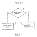
- the control device 12 generates the 6 bit signals for the CRT display device 13, as shown in the Table 2, and responds to the fact that the plasma display device 11 has been selected by the operator, to activates the circuit of the Fig. 1 to convert one 6 bit signal to four 4 bit signals.
- the operations are shown in blocks 22, 23 and 24 of Fig. 2. If the answer of the block 22 is No, the control device 12 does not activate the circuit of the Fig. 1, in the block 24.
- the display device 13 has 400 scan lines and displays 200 dots in the vertical direction. That is, two scan lines are used to display one dot.
- the upper half of the dot is displayed by the upper scan line OA, and the lower half of the dot is displayed by the lower scan line OB, so that one dot is displayed.
- the control device 12 generates the same signals during the scans of the upper and lower scan lines OA and OB.
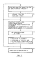
- the control device 12 In a block 31 in the Fig. 3, the control device 12 generates the first gray level signal for the dot position (X, Y) of the display device 13, and stores it in the register 1. The operations of the block 31 are repeated two times for the upper and lower scan lines OA and OB. The operation starts from the upper scan line OA. During displaying the upper half of dot (0, 0) by the upper scan line, the second gray level signals for the dots (0, 0) and (1, 0) of the display device 11 are generated.
- the control device 12 generates the first gray level signal 101010 (decimal value 42).
- the value is stored in the register 1.
- the control device 12 in the block 32, supplies the higher 4 bits, i.e. M bits, 1010 of the 101010 into the lower 4 bit positions of the register 4 through the line 2.
- the higher 2 bit positions of the register 4 are always 0 0.
- the reasons for concatenating the higher 2 bits in the register 4 will be described latter.
- the control device 12 uses the lower 2 bits, i.e. N-M bits, on the line 3 of the first gray level signal 101010 as an address to select one of the Tables 5, 6, 7 and 8 (block 33).
- the number of the tables are represented by 2 N-M , and in this embodiment, 4 tables are prepared.
- the modification value is represented by the decimal value, 0 corresponds to the binary value 00000, 1 corresponds to the binary value 00001, and these binary values are stored in the table. Any value in the range of +15 - -15 is used as the modification value. From the viewpoint of fidelity, the preferred range is +3 - -3.
- the modification value has 5 bits representing +15 - -15, and a negative value is represented by complement of 2.
- the higher 1 bit is concatenated to the 5 bits from the table by a sign extension.
- the modification value is +1
- 00001 is stored in the table
- 0 is concatenated to the 00001 by the sign extension, so that the input to the adder 9 is 000001.
- the modification value in the table is -1
- 11111 is stored in the table
- 1 is concatenated to the 11111 by the sign extension, so that 111111 is supplied to the adder 9.
- the 2 bits are concatenated in the register 4.
- control device 12 concatenates the bit 0 to the upper left modification value 00000 in the Table 7, and supplies the 000000 to the adder 9.
- control device 12 activates the adder 9 to add both the inputted bits. That is, the 000000 representing the upper left modification value 0 in the Table 7 is added to the 001010 (2 + M bits), and the total value 001010 is generated.
- the control device 12 supplies the total value 001010 to the discrimination device 10.
- the discrimination device 10 generates on the output line the value 15 (binary value 1111), if the total value is larger than 15, generates 0 (binary value 0000) on the output line, if the total value is smaller than 0, that is the total value is negative value, and supplies the lower 4 bits of the total value on the output line if the total value satisfies 15 ⁇ total value ⁇ 0 (block 35).
- the upper 2 bits of the total value are determined or tested.
- the most significant bit of the total value is 1, it indicates that the total value is negative, when the higher 2 bits of the total value is 01, it indicates that the total value is larger than 15, and when the higher 2 bits of the total value is 00, it indicates that the relation 15 ⁇ total value ⁇ 0 is satisfied.
- the value is 001010
- the 4 bits 1010 is supplied to the display device 11 as the second gray level signal for the dot (0, 0) in the area 14A of the display device 11, whereby the gray level 10 (i.e. binary value 1010) is displayed at the dot (0, 0) of the display device 11.
- the control device 12 reads out the upper right modification value 1 (binary value 00001) in the Table 7, converts it to the 6 bits 000001 by the sign extension, supplies the 6 bits to the adder 9 and supplies the 6 bits 001010 in the 2+M register 4 to the adder 9.
- both the values are added.
- the total value is 001011 and it satisfies 15 ⁇ total value ⁇ 0, the bits 1011 is supplied to the display device 11 as the second gray level signal for the dot (1, 0) in the area 14A of the display device 11, whereby the gray level 11 (binary value 1011) is displayed at the dot (1, 0) of the display device 11.
- the control device 12 performs the level conversion for the second dot (1, 0) in the dot line 0 of the display device 13, in the same manner, whereby the second gray level signals for the dots (2, 0) and (3, 0) in the area 14B of the display device 11 are generated and these dots are displayed. In this manner, whenever the third dot and subsequent dots in the dot line 0 of the display device 13 are displayed, two dots in the area 14C and the subsequent areas are displayed. In this manner, the same image is displayed on both the display devices 11 and 13, wherein the number of gray levels and the number of dots of the display device 13 differ from that of the display device 11. In other cases, only the display device 11 is operated, while the display device 13 is not operated, and vice versa.
- the control device 12 starts the lower scan line OB of the dot line 0 of the display device 13.
- the same first gray level signals as that used for the upper scan line OA are used again to display the lower half of each dot in the dot line 0 of the display device 13, during which the second gray level signals for the dot lien 1 of the display device 11 are generated. That is, the first gray level signal 101010 for the dot (0, 0) of the display device 13 is stored in the register 4, again (block 31 in the Fig. 3).
- the operations of the blocks 32 and 33 are performed to select the Table 7.
- the lower left modification value 1 (00001) in the Table 7 is read out, and the sign extension is performed, and the value 000001 is added to the 6 bits 001010 of the register 4, and the total value 001011 is supplied to the discrimination device 10. Since the total value 001011 satisfies 15 ⁇ total value ⁇ 0, the 4 bit second gray level signal 1011 representing the total value 001011 is used to display the gray level 11 at the dot (0, 1) in the area 14A of the display device 11.
- the control device 12 reads out the lower right modification value 00000 in the Table 7, performs the sign extension to generate 000000, and supplies it to the adder 9.
- the adder 9 adds the value 000000 and the value 001010 of the register 4 to generate the total value 001010 (block 34).
- the total value 001010 is determined in the discrimination device 10 (block 35).
- the second gray level signal 1010 representing the total value is used to display the gray level 10 (1010) at the dot (1, 1) in the area 14A of the display device 11.
- the second gray level signals for the four dots (0, 0), (1, 0), (0, 1) an 1, 1) in the area 14A of the display device 11 are generated.
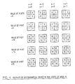
- Fig. 4 shows the gray levels of the second signals for the four dots in the areas 14 generated for the value of the M bits, in the case that the modification values in the Tables 5, 6, 7 and 8 are used.
- the values shown in the Table 1 are used as P and Q.
- the display devices 11 and 13 were described as the plasma display device and CRT display device, respectively, other types of display devices, such as a liquid crystal display device, an electroluminescence display device could be used. And, by using other values as the modification values of the Tables 5, 6, 7 and 8, the characteristics of the gray levels displayed on the display device 11 could be varied.
- the receptionist sees one display device of a display station, with the backside of the display device being faced to the customer, and it is required to prepare the other display device for the customer.
- the lower gray level display device is used by the receptionist, and the high gray level display device is prepared for the customer.
- both the receptionist and customer see the same image on their display device.
- the display device 11 displays only 16 gray levels for each dot, the display device 11 displays the 61 gray levels by using four dots for one dot of the display device 13 and displaying the image of the one dot of the display device 13 on the four dots on the display device 11.
Landscapes
- Engineering & Computer Science (AREA)
- Theoretical Computer Science (AREA)
- Physics & Mathematics (AREA)
- General Physics & Mathematics (AREA)
- Computer Hardware Design (AREA)
- Human Computer Interaction (AREA)
- General Engineering & Computer Science (AREA)
- Control Of Indicators Other Than Cathode Ray Tubes (AREA)
- Controls And Circuits For Display Device (AREA)
- Facsimile Image Signal Circuits (AREA)
- Image Processing (AREA)
- Liquid Crystal Display Device Control (AREA)
Applications Claiming Priority (2)
| Application Number | Priority Date | Filing Date | Title |
|---|---|---|---|
| JP236291/88 | 1988-09-22 | ||
| JP63236291A JPH0650522B2 (ja) | 1988-09-22 | 1988-09-22 | 表示システム |
Publications (3)
| Publication Number | Publication Date |
|---|---|
| EP0360402A2 true EP0360402A2 (fr) | 1990-03-28 |
| EP0360402A3 EP0360402A3 (fr) | 1991-10-16 |
| EP0360402B1 EP0360402B1 (fr) | 1995-02-15 |
Family
ID=16998614
Family Applications (1)
| Application Number | Title | Priority Date | Filing Date |
|---|---|---|---|
| EP89308052A Expired - Lifetime EP0360402B1 (fr) | 1988-09-22 | 1989-08-08 | Système d'affichage de données numériques |
Country Status (8)
| Country | Link |
|---|---|
| US (1) | US5059962A (fr) |
| EP (1) | EP0360402B1 (fr) |
| JP (1) | JPH0650522B2 (fr) |
| KR (1) | KR920005288B1 (fr) |
| CN (1) | CN1019239B (fr) |
| DE (1) | DE68921123T2 (fr) |
| GB (1) | GB2223149A (fr) |
| HK (1) | HK90395A (fr) |
Cited By (6)
| Publication number | Priority date | Publication date | Assignee | Title |
|---|---|---|---|---|
| EP0428356A3 (en) * | 1989-11-13 | 1992-09-30 | Canon Kabushiki Kaisha | Pattern generation method and pattern generation apparatus |
| EP0485950A3 (en) * | 1990-11-13 | 1992-11-25 | Nec Corporation | Method and apparatus for coding/decoding image signal |
| EP0536975A3 (en) * | 1991-10-07 | 1993-10-20 | Fujitsu Ltd | Method of driving surface-stabilised ferroelectric liquid crystal display element for increasing the number of gray scales |
| EP0581256A3 (en) * | 1992-07-31 | 1994-06-01 | Eastman Kodak Co | Progressive bit plane reconstruction method |
| EP0545577A3 (fr) * | 1991-12-03 | 1995-12-20 | International Business Machines Corporation | Système d'affichage |
| US6865294B2 (en) * | 2000-10-03 | 2005-03-08 | Fuji Xerox Co., Ltd. | Image reproducing apparatus, image reproducing method, and computer readable storage medium |
Families Citing this family (11)
| Publication number | Priority date | Publication date | Assignee | Title |
|---|---|---|---|---|
| JPH0743580B2 (ja) * | 1988-09-22 | 1995-05-15 | インターナショナル・ビジネス・マシーンズ・コーポレーション | グレイ・スケールを変換する方法 |
| JPH0455890A (ja) * | 1990-06-25 | 1992-02-24 | Canon Inc | 画像データ制御装置及び表示システム |
| JP3137367B2 (ja) * | 1990-08-09 | 2001-02-19 | 株式会社東芝 | カラーパネル表示制御システム及びコンピュータシステム |
| JPH04316276A (ja) * | 1991-04-16 | 1992-11-06 | Ricoh Co Ltd | 画像形成装置 |
| JPH06318060A (ja) * | 1991-07-31 | 1994-11-15 | Toshiba Corp | 表示制御装置 |
| US5484632A (en) * | 1993-10-07 | 1996-01-16 | Eastman Chemical Company | Non-oriented, heat-sealing polyester film |
| US6034664A (en) * | 1997-06-25 | 2000-03-07 | Sun Microsystems, Inc. | Method and apparatus for pseudo-random noise generation based on variation of intensity and coloration |
| US6008794A (en) * | 1998-02-10 | 1999-12-28 | S3 Incorporated | Flat-panel display controller with improved dithering and frame rate control |
| GB2354679B (en) * | 1999-07-26 | 2003-08-27 | Ibm | Colour reduction for a remote control system |
| JP7007789B2 (ja) | 2015-06-26 | 2022-01-25 | シナプティクス・ジャパン合同会社 | 表示パネルドライバ及び表示パネルの駆動方法 |
| CN105163097B (zh) * | 2015-08-28 | 2017-09-05 | 深圳Tcl数字技术有限公司 | 图像信号的处理方法及装置 |
Family Cites Families (8)
| Publication number | Priority date | Publication date | Assignee | Title |
|---|---|---|---|---|
| US3937878A (en) * | 1975-01-21 | 1976-02-10 | Bell Telephone Laboratories, Incorporated | Animated dithered display systems |
| US4006298A (en) * | 1975-05-20 | 1977-02-01 | Gte Laboratories Incorporated | Bistable matrix television display system |
| US4580134A (en) * | 1982-11-16 | 1986-04-01 | Real Time Design, Inc. | Color video system using data compression and decompression |
| US4558370A (en) * | 1983-11-21 | 1985-12-10 | International Business Machines Corporation | Image processing method for graphics images |
| JPS61213896A (ja) * | 1985-03-19 | 1986-09-22 | 株式会社 アスキ− | デイスプレイコントロ−ラ |
| NL8501845A (nl) * | 1985-06-27 | 1987-01-16 | Oce Nederland B V Patents And | Werkwijze voor het vergroten/verkleinen van ditherbeelden. |
| JPH0782306B2 (ja) * | 1986-05-30 | 1995-09-06 | 株式会社日立製作所 | ビデオインターフェース方法及び装置 |
| US5123059A (en) * | 1987-09-28 | 1992-06-16 | Dainippon Screen Mfg. Co., Ltd. | Gradation converting circuit employing lookup table |
-
1988
- 1988-09-22 JP JP63236291A patent/JPH0650522B2/ja not_active Expired - Lifetime
-
1989
- 1989-06-06 GB GB8913015A patent/GB2223149A/en not_active Withdrawn
- 1989-08-08 EP EP89308052A patent/EP0360402B1/fr not_active Expired - Lifetime
- 1989-08-08 DE DE68921123T patent/DE68921123T2/de not_active Expired - Fee Related
- 1989-08-19 CN CN89106444A patent/CN1019239B/zh not_active Expired
- 1989-08-21 KR KR1019890011871A patent/KR920005288B1/ko not_active Expired
- 1989-09-22 US US07/412,029 patent/US5059962A/en not_active Expired - Fee Related
-
1995
- 1995-06-08 HK HK90395A patent/HK90395A/en unknown
Cited By (8)
| Publication number | Priority date | Publication date | Assignee | Title |
|---|---|---|---|---|
| EP0428356A3 (en) * | 1989-11-13 | 1992-09-30 | Canon Kabushiki Kaisha | Pattern generation method and pattern generation apparatus |
| EP0485950A3 (en) * | 1990-11-13 | 1992-11-25 | Nec Corporation | Method and apparatus for coding/decoding image signal |
| EP0536975A3 (en) * | 1991-10-07 | 1993-10-20 | Fujitsu Ltd | Method of driving surface-stabilised ferroelectric liquid crystal display element for increasing the number of gray scales |
| US5856815A (en) * | 1991-10-07 | 1999-01-05 | Fujitsu Limited | Method of driving surface-stabilized ferroelectric liquid crystal display element for increasing the number of gray scales |
| EP0545577A3 (fr) * | 1991-12-03 | 1995-12-20 | International Business Machines Corporation | Système d'affichage |
| CN1040805C (zh) * | 1991-12-03 | 1998-11-18 | 国际商业机器公司 | 显示系统 |
| EP0581256A3 (en) * | 1992-07-31 | 1994-06-01 | Eastman Kodak Co | Progressive bit plane reconstruction method |
| US6865294B2 (en) * | 2000-10-03 | 2005-03-08 | Fuji Xerox Co., Ltd. | Image reproducing apparatus, image reproducing method, and computer readable storage medium |
Also Published As
| Publication number | Publication date |
|---|---|
| KR900005273A (ko) | 1990-04-13 |
| CN1043017A (zh) | 1990-06-13 |
| KR920005288B1 (ko) | 1992-06-29 |
| GB8913015D0 (en) | 1989-07-26 |
| EP0360402A3 (fr) | 1991-10-16 |
| JPH0285974A (ja) | 1990-03-27 |
| GB2223149A (en) | 1990-03-28 |
| US5059962A (en) | 1991-10-22 |
| JPH0650522B2 (ja) | 1994-06-29 |
| DE68921123T2 (de) | 1995-08-10 |
| HK90395A (en) | 1995-06-16 |
| DE68921123D1 (de) | 1995-03-23 |
| EP0360402B1 (fr) | 1995-02-15 |
| CN1019239B (zh) | 1992-11-25 |
Similar Documents
| Publication | Publication Date | Title |
|---|---|---|
| EP0360402A2 (fr) | Système d'affichage de données numériques | |
| US6246421B1 (en) | Apparatus and method for parallel rendering of image pixels | |
| US5155478A (en) | Method and apparatus for converting gray scale | |
| US5652605A (en) | Display controller for a flat display apparatus | |
| EP0619675A1 (fr) | Système d'affichage d'images en couleur | |
| EP0545577B1 (fr) | Système d'affichage et procédé | |
| EP0387550A1 (fr) | Dispositif de contrôle d'affichage | |
| EP0480564B1 (fr) | Améliorations d'un affichage à balaye de trame | |
| US4827353A (en) | Method of and circuit arrangement for changing the resolution of binary pseudo-halftone pictures | |
| US7061504B1 (en) | Method and apparatus for configurable gamma correction in a video graphics circuit | |
| US6173089B1 (en) | Image handling system and method | |
| JP2000338935A (ja) | 階調補正装置、画像表示装置および階調補正方法 | |
| US5854633A (en) | Method of and system for dynamically adjusting color rendering | |
| US5140544A (en) | Divide-by-five divider | |
| US3975584A (en) | Dither threshold generators | |
| US5937146A (en) | Binarization processing apparatus and method | |
| JPH06138844A (ja) | 階調表示装置 | |
| KR890006505Y1 (ko) | 그래픽에 있어서 모니터 모드 변환회로 | |
| JP3017003B2 (ja) | 画像処理装置 | |
| EP0970582A1 (fr) | Decimateur bilineaire a compensation d'erreurs | |
| JPH0916756A (ja) | 色信号系変換装置 | |
| EP0185328A2 (fr) | Système de commande d'affichage | |
| JPH07262349A (ja) | ディザ変調方法及び回路、ディザテーブル用アドレス発生方法及び回路並びにこれらを用いたハードコピー回路 | |
| JPH0446391A (ja) | 画像表示装置 | |
| JPH05241552A (ja) | カラーlcd用デジタルrgbインターフェース |
Legal Events
| Date | Code | Title | Description |
|---|---|---|---|
| PUAI | Public reference made under article 153(3) epc to a published international application that has entered the european phase |
Free format text: ORIGINAL CODE: 0009012 |
|
| AK | Designated contracting states |
Kind code of ref document: A2 Designated state(s): DE FR GB |
|
| 17P | Request for examination filed |
Effective date: 19900723 |
|
| PUAL | Search report despatched |
Free format text: ORIGINAL CODE: 0009013 |
|
| AK | Designated contracting states |
Kind code of ref document: A3 Designated state(s): DE FR GB |
|
| 17Q | First examination report despatched |
Effective date: 19930910 |
|
| GRAA | (expected) grant |
Free format text: ORIGINAL CODE: 0009210 |
|
| AK | Designated contracting states |
Kind code of ref document: B1 Designated state(s): DE FR GB |
|
| REF | Corresponds to: |
Ref document number: 68921123 Country of ref document: DE Date of ref document: 19950323 |
|
| ET | Fr: translation filed | ||
| PGFP | Annual fee paid to national office [announced via postgrant information from national office to epo] |
Ref country code: GB Payment date: 19950726 Year of fee payment: 7 |
|
| PGFP | Annual fee paid to national office [announced via postgrant information from national office to epo] |
Ref country code: FR Payment date: 19950807 Year of fee payment: 7 |
|
| PGFP | Annual fee paid to national office [announced via postgrant information from national office to epo] |
Ref country code: DE Payment date: 19950821 Year of fee payment: 7 |
|
| PLBE | No opposition filed within time limit |
Free format text: ORIGINAL CODE: 0009261 |
|
| STAA | Information on the status of an ep patent application or granted ep patent |
Free format text: STATUS: NO OPPOSITION FILED WITHIN TIME LIMIT |
|
| 26N | No opposition filed | ||
| PG25 | Lapsed in a contracting state [announced via postgrant information from national office to epo] |
Ref country code: GB Effective date: 19960808 |
|
| GBPC | Gb: european patent ceased through non-payment of renewal fee |
Effective date: 19960808 |
|
| PG25 | Lapsed in a contracting state [announced via postgrant information from national office to epo] |
Ref country code: FR Effective date: 19970430 |
|
| PG25 | Lapsed in a contracting state [announced via postgrant information from national office to epo] |
Ref country code: DE Effective date: 19970501 |
|
| REG | Reference to a national code |
Ref country code: FR Ref legal event code: ST |