EP0363976A1 - Relais électromagnétique - Google Patents
Relais électromagnétique Download PDFInfo
- Publication number
- EP0363976A1 EP0363976A1 EP89119015A EP89119015A EP0363976A1 EP 0363976 A1 EP0363976 A1 EP 0363976A1 EP 89119015 A EP89119015 A EP 89119015A EP 89119015 A EP89119015 A EP 89119015A EP 0363976 A1 EP0363976 A1 EP 0363976A1
- Authority
- EP
- European Patent Office
- Prior art keywords
- contact
- coil
- point
- slide
- base body
- Prior art date
- Legal status (The legal status is an assumption and is not a legal conclusion. Google has not performed a legal analysis and makes no representation as to the accuracy of the status listed.)
- Granted
Links
- 230000013011 mating Effects 0.000 claims description 9
- 239000000463 material Substances 0.000 abstract description 2
- 208000035874 Excoriation Diseases 0.000 description 7
- 238000005299 abrasion Methods 0.000 description 7
- 238000009434 installation Methods 0.000 description 7
- 238000009413 insulation Methods 0.000 description 4
- 238000006073 displacement reaction Methods 0.000 description 3
- 238000005192 partition Methods 0.000 description 2
- 238000005452 bending Methods 0.000 description 1
- 229910052729 chemical element Inorganic materials 0.000 description 1
- 238000004140 cleaning Methods 0.000 description 1
- 230000008878 coupling Effects 0.000 description 1
- 238000010168 coupling process Methods 0.000 description 1
- 238000005859 coupling reaction Methods 0.000 description 1
- 239000000428 dust Substances 0.000 description 1
- 230000000694 effects Effects 0.000 description 1
- 239000011810 insulating material Substances 0.000 description 1
- 238000004519 manufacturing process Methods 0.000 description 1
- 239000002245 particle Substances 0.000 description 1
- 238000005096 rolling process Methods 0.000 description 1
- 238000003860 storage Methods 0.000 description 1
- 238000003466 welding Methods 0.000 description 1
Images
Classifications
-
- H—ELECTRICITY
- H01—ELECTRIC ELEMENTS
- H01H—ELECTRIC SWITCHES; RELAYS; SELECTORS; EMERGENCY PROTECTIVE DEVICES
- H01H50/00—Details of electromagnetic relays
- H01H50/54—Contact arrangements
-
- H—ELECTRICITY
- H01—ELECTRIC ELEMENTS
- H01H—ELECTRIC SWITCHES; RELAYS; SELECTORS; EMERGENCY PROTECTIVE DEVICES
- H01H1/00—Contacts
- H01H1/60—Auxiliary means structurally associated with the switch for cleaning or lubricating contact-making surfaces
-
- H—ELECTRICITY
- H01—ELECTRIC ELEMENTS
- H01H—ELECTRIC SWITCHES; RELAYS; SELECTORS; EMERGENCY PROTECTIVE DEVICES
- H01H3/00—Mechanisms for operating contacts
- H01H3/001—Means for preventing or breaking contact-welding
Definitions
- the invention relates to an electromagnetic relay with a base body with a bottom surface forming the connection side of the relay, an electromagnetic system arranged on the base body with coil, core and armature, a contact arrangement anchored in the base body with at least one mating contact element and at least one movable contact spring, the contact points of which provided contact legs run substantially perpendicular to the bottom surface, and an actuating element which transmits the armature movement to the contact spring.
- Such a relay is described for example in DE_C_ 34 14 731.
- an actuating slide is located above the magnet system with respect to the connection side of the relay and also above the contact arrangement, the slide acting on a central contact spring directly above the contact points. Since the slide must be made of plastic material, a certain amount of abrasion can never be completely avoided. In the normal installation position of the relay, however, this abrasion falls downwards in the direction of the contact pieces, and there is a risk that, over time, the finest particles from the insulating material of the slide will contaminate the contact surfaces and increase the contact resistance.
- a similarly constructed relay is known from DE-A-35 39 944, although the slide is located on the connection side of the relay below the magnet system. In the normal installation position of the relay, the contact points are above the slide, so that the abrasion does not fall on the contact surfaces.
- this arrangement with the slide located between the contact points and the connection side has the Disadvantage that a changeover contact cannot be formed easily since the centrally arranged slide would intersect with the second mating contact element which is also centrally arranged.
- the second mating contact element with a recess for the slide, this results in a complicated manufacture and assembly. It must also be borne in mind that relays on printed circuit boards can also be installed so that the connection side is on top. In this case, the coupling point between slide and contact spring would also lie above the contact point and the abrasion dust would fall on the contact surfaces in the second-mentioned relay.
- the object of the invention is to provide a relay of the type mentioned, in which the risk of abrasion falling from the actuating element onto the contact points is largely avoided, while at the same time achieving a simple structure and simple assignment between the contact arrangement, magnet system and actuating element becomes.
- this object is achieved in the relay of the type mentioned at the outset in that the contact point and the point of application of the actuating element on the contact spring are offset from one another in such a way that they are spaced apart from one another in the projection onto the floor surface.
- the actuating element engages laterally offset with respect to the contact point on the actuating element, so that the point of attack is neither above the contact point in the normal installation position nor in the reverse installation position. Due to the laterally offset arrangement, an actuating element can easily be guided past a mating contact element even in the case of a changeover contact, without this requiring a special shape of the contact element or of the actuating element.
- a laterally offset actuation of the contact spring also brings with it the advantage that the torsion movement caused thereby in the contact spring causes the contact pieces to roll off, which enables a self-cleaning effect or easier tearing of the contacts when they are slightly welded by the switching arc.
- the point of attack of the actuating element may lie above the contact point.
- the contact point and the point of application of the actuating element are additionally offset with respect to one another in terms of height with respect to the base surface.
- the contact point and actuation point of the contact spring are offset with respect to one another with respect to the connection side, so that when standing or lying installation in any position, the resulting abrasion falls down next to the contacts and thus the contact points are no longer directly contaminated.
- the contact point and the actuation point of the contact spring could only lie one above the other if the relay were installed in a specific inclined position, which is extremely unlikely.
- the design according to the invention can be used particularly advantageously in a relay in which the coil has its axis parallel to the bottom surface, the armature is arranged approximately perpendicular to the bottom surface on one end of the coil and the contact arrangement is arranged in front of the end face of the coil opposite the armature , as is known from DE-C-34 14 731 already mentioned at the beginning.
- a rod-shaped, on the outside of the coil in the direction of the coil serves as the actuating element lenachse extending slider, wherein the contact points of the contact arrangement with respect to a through the coil axis, perpendicular to the bottom surface plane are arranged on one side and the slider on the other side.
- the slide is arranged between the coil and the base plate.
- an actuating tab offset at an angle to the contact point is expediently formed or cut onto the free end of the contacting leg of the contact spring.
- this actuating flap can be made particularly narrow, or a web with a reduced cross-section can be provided between it and the actual contact leg.
- the contact spring itself has approximately the shape of an inverted U, wherein it is fastened with one leg to a connecting element anchored in the base body and carries a contact piece on the second leg and forms an engagement point for the slide.
- a connecting element anchored in the base body
- the connection element for the contact spring is anchored in the area of the opposite side of the base body, the two legs of the contact spring being offset obliquely to one another in parallel planes .
- the connecting ele ment for the contact spring can also have a reduced cross-section adjustment web.
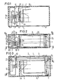
- the relay shown in FIGS. 1 to 3 has a base body 1 with a bottom surface 1a and a configuration shown in more detail in FIG.
- a magnet system with a coil 2, a core 3 arranged inside the coil in the axial direction, an angular yoke 4 and a flat armature 5 is arranged on the base body 1.
- the coil axis runs parallel to the connection level of the relay.
- the yoke 4 is arranged so that its short leg 4a extends perpendicular to the connection plane in front of one end face of the coil and is connected to the core, while its long leg 4b extends parallel to the connection plane but above the coil 2 and at its free end End forms a storage for the anchor 5.
- a leaf spring 6 designed as a bearing plate and armature spring is used, the special design of which is described and illustrated in EP-A-0 251 034.
- the armature 5 extends in front of the end face of the coil opposite the yoke leg 4a and forms a working air with the free end of the core 3 gap.
- the plate-shaped armature 5 extends approximately perpendicular to the connection plane of the relay, so that its free end 5a is located on the underside of the magnet system.
- This free end 5a is coupled to a rod-shaped slide 7, which extends below the coil 2 parallel to its axis, but is offset from the center to one side.
- a contact arrangement is anchored in the base body 1 in front of the end of the coil 2 opposite the armature.
- This contact arrangement consists of two fixed mating contact elements 8 and 9 with contact pieces 8a and 9a and a center contact spring 10.
- the mating contact elements 8 and 9 are anchored with their angled connecting elements 8b and 9b in corresponding slots or openings 11 and 12 of the base body.
- the counter-contact elements 8 and 9 are arranged opposite to the slide 7 from the center to the side.
- the center contact spring 10 is fastened with a connection bracket 13 in an opening 14 of the base body on the side of the slide 7.
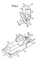
- the special shape of the contact spring 10 can be seen in the perspective view of FIG. 4.
- the spring has approximately a U-shape with a fastening leg 15, a middle part 16 and a contact leg 17.
- the middle part 16 has approximately the shape of a parallelogram, so that the contact leg 17 is offset parallel to the fastening leg 15.
- the mounting leg 15 is thus with the connection bracket 13 on one side of the base body in the extension of the slide 7, while the contact leg 17 is on the other side of the base body between the counter-contact elements 8 and 9.
- This shape of the contact spring 10 results on the one hand in a large spring length, but on the other hand also the possibility of isolating the connection angle 13 far from the connection legs 8b or 9b of the mating contact elements in the insulation Arrange base body.
- the base body 1 also has an upwardly formed partition wall 18.
- an actuating tab 19 is integrally formed on the free end of the contact leg 17, which is located in the extension of the slider 7 and in a recess 20 of the Basic body extends in which the slide is also located.
- a pin 7a formed at the end of the slide 7 engages in a recess 19a of the actuating tab 19.
- the other end of the slide 7 is coupled to the armature in the same way by a pin 7b.
- the offset arrangement of the actuating tab 19 with respect to the contact leg 17 also has the advantage that a certain torsional stress on the contact spring 10 and thus a rolling movement on the contact piece 17a is generated when actuated. As a result, the contact can be broken more easily even after light welding.
- the force-displacement characteristic of the relay can also be set.
- An additional could also be used to further tune this force-displacement characteristic cher slot 22 (indicated by dashed lines in FIG 4) can be provided in this area.
- connection bracket 13 In order to be able to adjust the position of the contact spring 10, a notch is provided on the connection bracket 13 to form a predetermined bending point 23. It should also be pointed out that a changeover contact arrangement is shown in the exemplary embodiment shown. By leaving the counter-contact element 9, a normally open contact can be obtained without any other change, and by opening the counter-contact element 8, an NC contact can be obtained.
- the structure of the base body can also be seen in the perspective view of FIG. 4.
- the special feature of the base body is the asymmetrical design of the support part 23 for the coil. This design creates a longitudinal channel 24 on one side, in which the slide 7 can extend as far as the depression 20.
- a shoe-like partition 25 is formed on the base body 1 for insulation between the coil 2, the core 3 and the yoke 4. After assembly of the functional parts on the base body, a cap 26 is slipped on from above, which additionally increases the insulation between the magnetic circuit and the contact arrangement with an intermediate wall 27.
Landscapes
- Physics & Mathematics (AREA)
- Electromagnetism (AREA)
- Electromagnets (AREA)
- Reciprocating, Oscillating Or Vibrating Motors (AREA)
- Magnetic Treatment Devices (AREA)
- Control Of High-Frequency Heating Circuits (AREA)
- Surgical Instruments (AREA)
- Valve Device For Special Equipments (AREA)
- Cookers (AREA)
- Relay Circuits (AREA)
Priority Applications (1)
| Application Number | Priority Date | Filing Date | Title |
|---|---|---|---|
| AT89119015T ATE92670T1 (de) | 1988-10-14 | 1989-10-12 | Elektromagnetisches relais. |
Applications Claiming Priority (2)
| Application Number | Priority Date | Filing Date | Title |
|---|---|---|---|
| DE3835118 | 1988-10-14 | ||
| DE3835118A DE3835118A1 (de) | 1988-10-14 | 1988-10-14 | Elektromagnetisches relais |
Publications (2)
| Publication Number | Publication Date |
|---|---|
| EP0363976A1 true EP0363976A1 (fr) | 1990-04-18 |
| EP0363976B1 EP0363976B1 (fr) | 1993-08-04 |
Family
ID=6365168
Family Applications (1)
| Application Number | Title | Priority Date | Filing Date |
|---|---|---|---|
| EP89119015A Expired - Lifetime EP0363976B1 (fr) | 1988-10-14 | 1989-10-12 | Relais électromagnétique |
Country Status (7)
| Country | Link |
|---|---|
| US (1) | US4958137A (fr) |
| EP (1) | EP0363976B1 (fr) |
| JP (1) | JPH0636340B2 (fr) |
| AT (1) | ATE92670T1 (fr) |
| DE (2) | DE3835118A1 (fr) |
| ES (1) | ES2041935T3 (fr) |
| PT (1) | PT91962B (fr) |
Cited By (3)
| Publication number | Priority date | Publication date | Assignee | Title |
|---|---|---|---|---|
| EP0487786A3 (en) * | 1990-11-29 | 1993-02-24 | Siemens Aktiengesellschaft | Relay |
| EP0669632A3 (fr) * | 1994-02-18 | 1997-09-24 | Siemens Ag | Relais à coulisseau mobile et procédé pour sa fabrication. |
| DE4115092C3 (de) * | 1991-05-08 | 1999-06-24 | Eberle Controls Gmbh | Elektromagnetisches Schaltrelais für Leiterplattenmontage |
Families Citing this family (17)
| Publication number | Priority date | Publication date | Assignee | Title |
|---|---|---|---|---|
| DE9013221U1 (de) * | 1990-09-18 | 1992-01-23 | Siemens AG, 80333 München | Elektromagnetisches Leistungsrelais mit Betätigungsschieber |
| EP0501070B2 (fr) * | 1991-02-27 | 2003-05-14 | Takamisawa Electric Co., Ltd. | Relais électromagnétique de petite dimension |
| AT402580B (de) * | 1991-10-07 | 1997-06-25 | Schrack Components Ag | Kontaktfeder, insbesondere für ein relais |
| JP3383984B2 (ja) * | 1992-05-14 | 2003-03-10 | オムロン株式会社 | 電磁継電器 |
| US5289144A (en) * | 1992-08-21 | 1994-02-22 | Potter & Brumfield, Inc. | Electromagnetic relay and method for assembling the same |
| AT404768B (de) * | 1993-07-02 | 1999-02-25 | Schrack Components Ag | Relais |
| US5872497A (en) * | 1996-10-23 | 1999-02-16 | Physio-Control Corporation | High energy transfer relay |
| NL1008747C2 (nl) * | 1998-03-30 | 1999-10-01 | Holec Holland Nv | Schakelaar met door een venster waarneembare contacten. |
| KR101435349B1 (ko) * | 2011-03-14 | 2014-08-27 | 오므론 가부시키가이샤 | 전자 계전기 |
| JP5085754B2 (ja) * | 2011-03-14 | 2012-11-28 | オムロン株式会社 | 電磁継電器 |
| JP4883232B1 (ja) * | 2011-03-14 | 2012-02-22 | オムロン株式会社 | 電磁継電器 |
| JP6025414B2 (ja) * | 2011-09-30 | 2016-11-16 | 富士通コンポーネント株式会社 | 電磁継電器 |
| JP6056264B2 (ja) * | 2012-08-24 | 2017-01-11 | オムロン株式会社 | 電磁石装置およびそれを用いた電磁継電器 |
| JP6043173B2 (ja) * | 2012-12-07 | 2016-12-14 | 富士通コンポーネント株式会社 | 電磁継電器 |
| JP6263904B2 (ja) * | 2013-08-23 | 2018-01-24 | オムロン株式会社 | 電磁石装置およびこれを用いた電磁継電器 |
| DE102014103247A1 (de) * | 2014-03-11 | 2015-09-17 | Tyco Electronics Austria Gmbh | Elektromagnetisches Relais |
| CH713442B1 (de) * | 2017-02-08 | 2021-03-31 | Elesta Gmbh Ostfildern De Zweigniederlassung Bad Ragaz | Relais. |
Citations (7)
| Publication number | Priority date | Publication date | Assignee | Title |
|---|---|---|---|---|
| DE1514538A1 (de) * | 1965-08-20 | 1969-05-14 | Siemens Ag | Elektromagnetisches Relais |
| DE1906109A1 (de) * | 1969-02-07 | 1970-08-20 | Ribler Pfeiffer Geb | Verfahren und Vorrichtung zur Steuerung von Webmaschinen |
| DE7037474U (de) * | 1970-10-10 | 1971-05-06 | Bach & Co | Elektrisches Relais |
| EP0161473A2 (fr) * | 1984-04-18 | 1985-11-21 | Hengstler GmbH Geschäftsbereich Haller-Relais | Relais miniature |
| DE3539944A1 (de) * | 1984-11-22 | 1986-05-28 | Eichhoff Espanola S.A., Valencia | Elektromagnetisches relais |
| EP0251034A1 (fr) * | 1986-06-23 | 1988-01-07 | Siemens Aktiengesellschaft | Relais électromagnétique |
| DD265732A1 (de) * | 1987-10-29 | 1989-03-08 | Grossbreitenbach Relaistech | Kontaktfedersatz fuer relais |
Family Cites Families (1)
| Publication number | Priority date | Publication date | Assignee | Title |
|---|---|---|---|---|
| US4740769A (en) * | 1986-06-23 | 1988-04-26 | Siemens Aktiengesellschaft | Electromagnetic relay |
-
1988
- 1988-10-14 DE DE3835118A patent/DE3835118A1/de not_active Withdrawn
-
1989
- 1989-09-15 US US07/408,070 patent/US4958137A/en not_active Expired - Lifetime
- 1989-10-12 EP EP89119015A patent/EP0363976B1/fr not_active Expired - Lifetime
- 1989-10-12 AT AT89119015T patent/ATE92670T1/de not_active IP Right Cessation
- 1989-10-12 ES ES198989119015T patent/ES2041935T3/es not_active Expired - Lifetime
- 1989-10-12 DE DE8989119015T patent/DE58905138D1/de not_active Expired - Lifetime
- 1989-10-12 PT PT91962A patent/PT91962B/pt not_active IP Right Cessation
- 1989-10-13 JP JP1265355A patent/JPH0636340B2/ja not_active Expired - Lifetime
Patent Citations (7)
| Publication number | Priority date | Publication date | Assignee | Title |
|---|---|---|---|---|
| DE1514538A1 (de) * | 1965-08-20 | 1969-05-14 | Siemens Ag | Elektromagnetisches Relais |
| DE1906109A1 (de) * | 1969-02-07 | 1970-08-20 | Ribler Pfeiffer Geb | Verfahren und Vorrichtung zur Steuerung von Webmaschinen |
| DE7037474U (de) * | 1970-10-10 | 1971-05-06 | Bach & Co | Elektrisches Relais |
| EP0161473A2 (fr) * | 1984-04-18 | 1985-11-21 | Hengstler GmbH Geschäftsbereich Haller-Relais | Relais miniature |
| DE3539944A1 (de) * | 1984-11-22 | 1986-05-28 | Eichhoff Espanola S.A., Valencia | Elektromagnetisches relais |
| EP0251034A1 (fr) * | 1986-06-23 | 1988-01-07 | Siemens Aktiengesellschaft | Relais électromagnétique |
| DD265732A1 (de) * | 1987-10-29 | 1989-03-08 | Grossbreitenbach Relaistech | Kontaktfedersatz fuer relais |
Cited By (3)
| Publication number | Priority date | Publication date | Assignee | Title |
|---|---|---|---|---|
| EP0487786A3 (en) * | 1990-11-29 | 1993-02-24 | Siemens Aktiengesellschaft | Relay |
| DE4115092C3 (de) * | 1991-05-08 | 1999-06-24 | Eberle Controls Gmbh | Elektromagnetisches Schaltrelais für Leiterplattenmontage |
| EP0669632A3 (fr) * | 1994-02-18 | 1997-09-24 | Siemens Ag | Relais à coulisseau mobile et procédé pour sa fabrication. |
Also Published As
| Publication number | Publication date |
|---|---|
| JPH0636340B2 (ja) | 1994-05-11 |
| JPH02165535A (ja) | 1990-06-26 |
| EP0363976B1 (fr) | 1993-08-04 |
| PT91962B (pt) | 1995-08-09 |
| PT91962A (pt) | 1990-04-30 |
| DE3835118A1 (de) | 1990-04-19 |
| US4958137A (en) | 1990-09-18 |
| ES2041935T3 (es) | 1993-12-01 |
| DE58905138D1 (de) | 1993-09-09 |
| ATE92670T1 (de) | 1993-08-15 |
Similar Documents
| Publication | Publication Date | Title |
|---|---|---|
| EP0363976B1 (fr) | Relais électromagnétique | |
| DE4135305C2 (fr) | ||
| EP0033841B1 (fr) | Relais | |
| EP0281950B1 (fr) | Relais électromagnétique | |
| EP0203496B1 (fr) | Relais électromagnétique | |
| WO1999026265A1 (fr) | Relais electromagnetique a fusible | |
| DE2728509A1 (de) | Elektromagnetisches relais, insbesondere leistungs-kleinrelais | |
| EP0834183B1 (fr) | Relais pour pouvoirs de coupure eleves | |
| EP0251034B1 (fr) | Relais électromagnétique | |
| DE2902885C2 (de) | Kontaktfederanordnung für elektromagnetische Drehankerrelais | |
| EP0199119A1 (fr) | Relais électromagnétique | |
| EP0099019A1 (fr) | Relais avec ressort de contact de pontage | |
| DE102006031584A1 (de) | Miniaturisierter elektrischer Schalter | |
| EP0476182A2 (fr) | Contacteur électromagnétique avec un coulisseau de commande | |
| DE2545180C3 (de) | Miniaturrelais | |
| EP0980578A1 (fr) | Relais electromagnetique | |
| DE3545356C2 (de) | Sicherheits-Schaltrelais | |
| EP0133582B1 (fr) | Relais électromagnétique | |
| EP0113440A1 (fr) | Relais électromagnétique | |
| EP0584122A1 (fr) | Relais electromagnetique. | |
| EP0091687A1 (fr) | Relais électromagnétique | |
| DE3400502C2 (de) | Elektrisches Relais | |
| DE3486050T2 (de) | Elektromagnetisches relais. | |
| EP0192928A1 (fr) | Relais électromagnétique | |
| EP0487786A2 (fr) | Relais |
Legal Events
| Date | Code | Title | Description |
|---|---|---|---|
| PUAI | Public reference made under article 153(3) epc to a published international application that has entered the european phase |
Free format text: ORIGINAL CODE: 0009012 |
|
| AK | Designated contracting states |
Kind code of ref document: A1 Designated state(s): AT BE CH DE ES FR GB IT LI NL SE |
|
| 17P | Request for examination filed |
Effective date: 19900528 |
|
| 17Q | First examination report despatched |
Effective date: 19920707 |
|
| GRAA | (expected) grant |
Free format text: ORIGINAL CODE: 0009210 |
|
| AK | Designated contracting states |
Kind code of ref document: B1 Designated state(s): AT BE CH DE ES FR GB IT LI NL SE |
|
| PG25 | Lapsed in a contracting state [announced via postgrant information from national office to epo] |
Ref country code: BE Effective date: 19930804 Ref country code: NL Effective date: 19930804 Ref country code: SE Effective date: 19930804 |
|
| REF | Corresponds to: |
Ref document number: 92670 Country of ref document: AT Date of ref document: 19930815 Kind code of ref document: T |
|
| REF | Corresponds to: |
Ref document number: 58905138 Country of ref document: DE Date of ref document: 19930909 |
|
| ITF | It: translation for a ep patent filed | ||
| ET | Fr: translation filed | ||
| GBT | Gb: translation of ep patent filed (gb section 77(6)(a)/1977) |
Effective date: 19931014 |
|
| REG | Reference to a national code |
Ref country code: ES Ref legal event code: FG2A Ref document number: 2041935 Country of ref document: ES Kind code of ref document: T3 |
|
| NLV1 | Nl: lapsed or annulled due to failure to fulfill the requirements of art. 29p and 29m of the patents act | ||
| PLBI | Opposition filed |
Free format text: ORIGINAL CODE: 0009260 |
|
| 26 | Opposition filed |
Opponent name: EH-SCHRACK COMPONENTS AKTIENGESELLSCHAFT Effective date: 19940429 |
|
| PLBM | Termination of opposition procedure: date of legal effect published |
Free format text: ORIGINAL CODE: 0009276 |
|
| STAA | Information on the status of an ep patent application or granted ep patent |
Free format text: STATUS: OPPOSITION PROCEDURE CLOSED |
|
| 27C | Opposition proceedings terminated |
Effective date: 19950918 |
|
| PGFP | Annual fee paid to national office [announced via postgrant information from national office to epo] |
Ref country code: AT Payment date: 19961008 Year of fee payment: 8 |
|
| PGFP | Annual fee paid to national office [announced via postgrant information from national office to epo] |
Ref country code: CH Payment date: 19970117 Year of fee payment: 8 |
|
| PG25 | Lapsed in a contracting state [announced via postgrant information from national office to epo] |
Ref country code: AT Free format text: LAPSE BECAUSE OF NON-PAYMENT OF DUE FEES Effective date: 19971012 |
|
| PG25 | Lapsed in a contracting state [announced via postgrant information from national office to epo] |
Ref country code: LI Free format text: LAPSE BECAUSE OF NON-PAYMENT OF DUE FEES Effective date: 19971031 Ref country code: CH Free format text: LAPSE BECAUSE OF NON-PAYMENT OF DUE FEES Effective date: 19971031 |
|
| REG | Reference to a national code |
Ref country code: CH Ref legal event code: PL |
|
| REG | Reference to a national code |
Ref country code: GB Ref legal event code: 732E |
|
| REG | Reference to a national code |
Ref country code: GB Ref legal event code: IF02 |
|
| PGFP | Annual fee paid to national office [announced via postgrant information from national office to epo] |
Ref country code: DE Payment date: 20081201 Year of fee payment: 20 |
|
| PGFP | Annual fee paid to national office [announced via postgrant information from national office to epo] |
Ref country code: ES Payment date: 20081027 Year of fee payment: 20 |
|
| PGFP | Annual fee paid to national office [announced via postgrant information from national office to epo] |
Ref country code: IT Payment date: 20081030 Year of fee payment: 20 |
|
| PGFP | Annual fee paid to national office [announced via postgrant information from national office to epo] |
Ref country code: FR Payment date: 20081018 Year of fee payment: 20 |
|
| PGFP | Annual fee paid to national office [announced via postgrant information from national office to epo] |
Ref country code: GB Payment date: 20081029 Year of fee payment: 20 |
|
| REG | Reference to a national code |
Ref country code: GB Ref legal event code: PE20 Expiry date: 20091011 |
|
| REG | Reference to a national code |
Ref country code: ES Ref legal event code: FD2A Effective date: 20091013 |
|
| PG25 | Lapsed in a contracting state [announced via postgrant information from national office to epo] |
Ref country code: ES Free format text: LAPSE BECAUSE OF EXPIRATION OF PROTECTION Effective date: 20091013 |
|
| PG25 | Lapsed in a contracting state [announced via postgrant information from national office to epo] |
Ref country code: GB Free format text: LAPSE BECAUSE OF EXPIRATION OF PROTECTION Effective date: 20091011 |